

Page 1
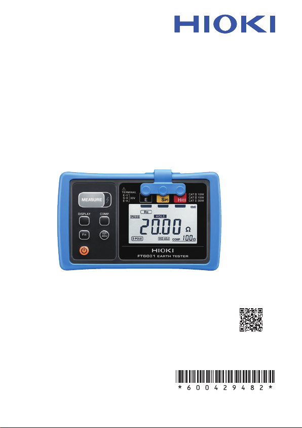
FT6031
EARTH TESTER
Instruction Manual
Video
Scan this code to watch
an instructional video.
Carrier charges may apply.
Oct. 2018 Revised edition 2
FT6031A981-02 18-10H
EN
Page 2

Page 3

Contents
Introduction .........................................................................1
Verifying Package Contents ..............................................1
Options (sold separately) ..................................................2
Safety Notes ........................................................................ 3
Usage Notes ........................................................................ 8
1 Overview 13
1.1 Overview and Features ................................. 13
Overview ................................................................... 13
Features .................................................................... 13
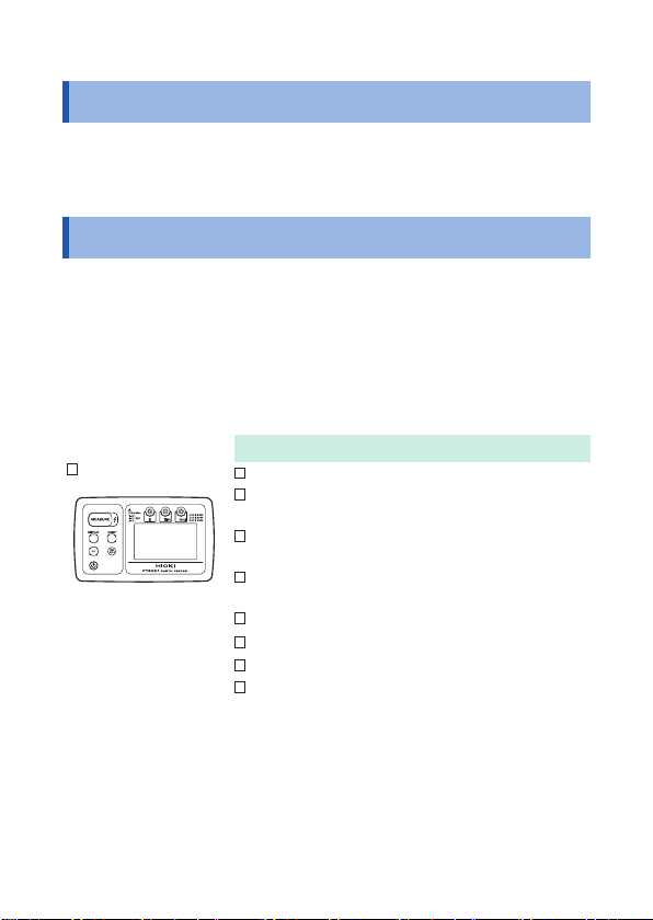
1.2 Parts Names and Functions ......................... 15
1.3 How to Use Carrying Case ...........................20
2 How to Measure 21
2.1 MeasurementWorkow ................................ 21
2.2 Attaching/Removing Protector ....................24
2.3 Inserting/Replacing Batteries ......................25
2.4 Inspection before Use ................................... 29
2.5 Setting Up Comparator (PASS/FAIL Test) ...31
How to set up comparator ......................................... 32
How to disable comparator ....................................... 32
2.6 Precise Measurement for Earth
Resistance(Precise Measurement
Method, Three-pole Method) ........................ 33
Performing zero adjustment ...................................... 35
Connecting measurement cables .............................36
Measuring earth resistance ......................................39
Stowing ..................................................................... 42
FT6031A981-02
i
Page 4

2.7 SimpliedMeasurementforEarth
Resistance(SimpliedMeasurement
Method, Two-pole Method) ........................... 44
Performing zero adjustment ...................................... 46
Connecting test leads ...............................................48
Measuring earth resistance ......................................51
Stowing ..................................................................... 51
2.8 Cautions and Tips for Measurement ...........52
Distance between earthing electrodes ......................52
Location to install auxiliary earthing rod ....................53
How to insert / pull out auxiliary earthing rod ............ 54
2.9 Auto Power Save
(Power-saving Function) ..............................56
2.10 Activating the LCD All-on Display ...............56
2.11 Displaying the Serial number .......................57
3 Specication 59
3.1 GeneralSpecication ...................................59
3.2 Measurement Function/Performance .......... 61
4 Maintenance and Service 67
4.1 Repair, Inspection, and Cleaning .................67
4.2 Troubleshooting ............................................69
4.3 Error Display .................................................. 73
Appendix Appx. 1
Appendix 1 Earth Resistance ...................Appx. 1
Appendix 2 Measurement Principle ......... Appx. 3
ii
Page 5
Introduction
Introduction
Thank you for purchasing the HIOKI FT6031 Earth Tester. To obtain
maximum performance from the product, please read this manual
rst, and keep it handy for future reference.
Verifying Package Contents
When you receive the instrument, inspect it carefully to ensure
that no damage occurred during shipping. In particular, check the
accessories, panel switches, and connectors. If damage is evident,
or if it fails to operate according to the specications, contact your
authorized Hioki distributor or reseller.
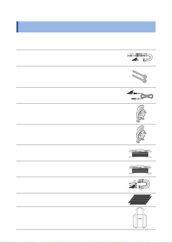
Check the package contents as follows.
FT6031
L9840
L9841 Measurement Cable
L9842-11 Measurement Cable
L9842-22 Measurement Cable
C0106 Carrying Case ×1
Protector
LR6 Alkaline battery × 4
Instruction manual
Accessory
Auxiliary Earthing Rod (2 piece set) ×1
(alligator clip, black 4 m) ×1
(yellow 10 m, equipped with winder) ×1
(red 20 m, equipped with winder) ×1
1
Page 6
Options (sold separately)
Options (sold separately)
The following options are available for the instrument. Contact your
authorized Hioki distributor or reseller when ordering.
L9787 Test Lead
L9840 Auxiliary Earthing Rod
L9841 Measurement Cable
L9842-11 Measurement Cable
(for simplied measurement method,
indoor use only, red and black 1.2 m each)
(for precision measurement method, 2 pcs in 1 set)
(φ 6 mm, entire length of 270 mm, straight
section 235 mm, material: stainless SUS304)
(for precision measurement method,
alligator clip, black 4 m)
(for precision measurement method,
yellow 10 m, equipped with winder)
L9842-22 Measurement Cable
L9843-51 Measurement Cable
L9843-52 Measurement Cable
L9844 Measurement Cable
9050 Earth Nets
C0106 Carrying Case
(for precision measurement method,
red 20 m, equipped with winder)
(for precision measurement method,
yellow 50 m, equipped with at cable winder)
(for precision measurement method,
red 50 m, equipped with at cable winder)
(for earthing terminal board, alligator clip,
3 cables in 1 set, red/yellow/black 1.2 m each)
(2 sheets in 1 set, 300 mm × 300 mm)
2
Page 7
Safety Notes
Safety Notes
This instrument is designed to conform to IEC 61010 Safety
Standards, and has been thoroughly tested for safety prior to
shipment. However, using the instrument in a way not described in
this manual may negate the provided safety features.
Before using the instrument, be certain to carefully read the following
safety notes.
DANGER
Mishandling during use could result in injury or death,
as well as damage to the instrument. Be certain that
you understand the instructions and precautions in
the manual before use.
WARNING
With regard to the electricity supply, there are risks
of electric shock, heat generation, re, and arc
discharge due to short circuits. If persons unfamiliar
with electricity measuring instruments are to use
the instrument, another person familiar with such
instruments must supervise operations.
3
Page 8
Safety Notes
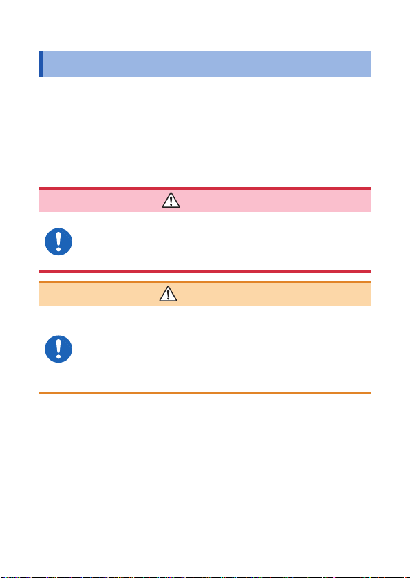
Notation
In this manual, the risk seriousness and the hazard levels are classied as
follows.
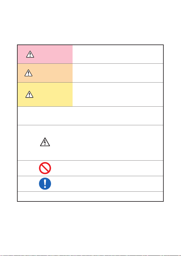
Indicates an imminently hazardous situation
DANGER
WARNING
CAUTION
IMPORTANT
that will result in death or serious injury to the
operator.
Indicates a potentially hazardous situation
that may result in death or serious injury to the
operator.
Indicates a potentially hazardous situation
that may result in minor or moderate injury to
the operator or damage to the instrument or
malfunction.
Indicates information related to the operation
of the instrument or maintenance tasks with
which the operators must be fully familiar.
Indicates a high voltage hazard.
If a particular safety check is not performed or
the instrument is mishandled, this may give
rise to a hazardous situation; the operator
may receive an electric shock, may get burnt
or may even be fatally injured.
Indicates prohibited actions.
Indicates the action which must be performed.
*
Additional information is presented below.
4
Page 9
Symbols afxed to the instrument
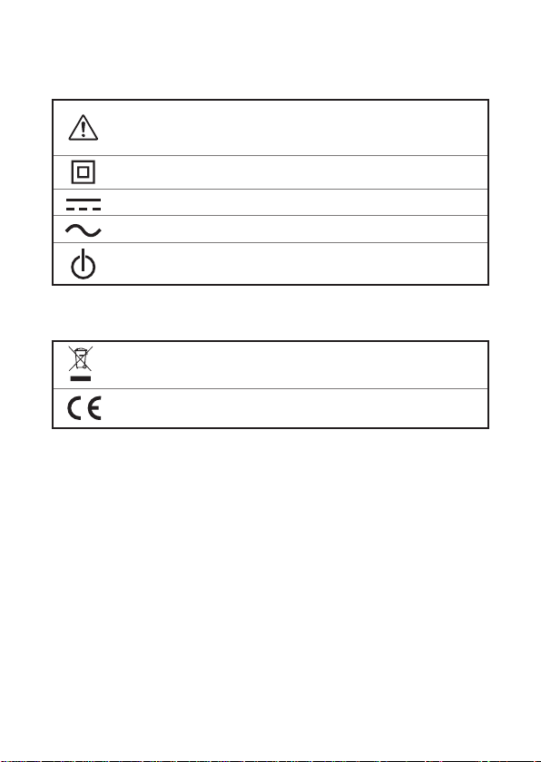
Indicates cautions and hazards. When the symbol is printed on
the instrument, refer to a corresponding topic in the Instruction
Manual.
Indicates a double-insulated device.
Indicates DC (Direct Current).
Indicates AC (Alternating Current).
Indicates the power switch mark.
Symbols for various standards
Indicates the Waste Electrical and Electronic Equipment
Directive (WEEE Directive) in EU member states.
Indicates that the instrument conforms to safety regulations set
out by the EC Directive.
Safety Notes
5
Page 10
Safety Notes
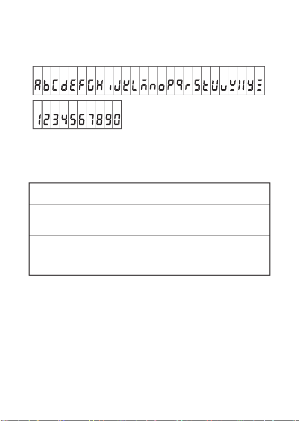
Screen display
This instrument uses the following screen displays.
A B C D E F G H I J K L M N O P Q R S T U V W X Y Z
1 2 3 4 5 6 7 8 9 0
Accuracy
We dene measurement tolerances in terms of f.s. (full scale), rdg.
(reading) and dgt. (digit) values, with the following meanings:
(Maximum display value)
f.s.
The maximum displayable value.
(Reading or displayed value)
rdg.
The value currently being measured and indicated on the
measuring instrument.
(Resolution)
The smallest displayable unit on a digital measuring
dgt.
instrument, i.e., the input value that causes the digital display
to show a “1” as the least-signicant digit.
6
Page 11
Safety Notes
Measurement categories
To ensure safe operation of measuring instruments, IEC 61010
establishes safety standards for various electrical environments,
categorized as CAT II to CAT IV, and called measurement categories.
DANGER
• Using a measuring instrument in an environment
designated with a higher-numbered category than
that for which the instrument is rated could result in
a severe accident, and must be carefully avoided.
• Using a measuring instrument without categories in
an environment designated with the CAT II to CAT
IV category could result in a severe accident, and
must be carefully avoided.
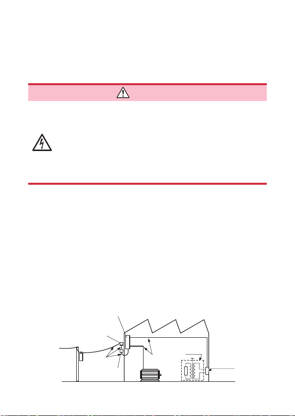
This instrument conforms to the safety requirements for CAT II 300 V, CAT III
150 V, CAT IV 100 V measuring instruments.
CAT II: When directly measuring the electrical outlet receptacles of
CAT III: When measuring the primary electrical circuits of heavy equipment
CAT IV: When measuring the circuit from the service drop to the service
the primary electrical circuits in equipment connected to an
AC electrical outlet by a power cord (portable tools, household
appliances, etc.).
(xed installations) connected directly to the distribution panel,
and feeders from the distribution panel to outlets.
entrance, and to the power meter and primary overcurrent
protection device (distribution panel).
Distribution Panel
Service Entrance
Service Drop
CAT IV
Power Meter
Internal Wiring
CAT III
Fixed Installation
CAT II
Outlet
7
Page 12
Usage Notes
Usage Notes
Follow these precautions to ensure safe operation and to obtain the
full benets of the various functions.
Verifying before usage
Before using the instrument, verify that it operates normally to
ensure that no damage occurred during storage or shipping. If
you nd any damage, contact your authorized Hioki distributor or
reseller.
DANGER
Before using the instrument, check that the coating
of the test leads and cables are neither ripped nor
torn and that no metal parts are exposed. Using the
instrument under such conditions could result in
electric shock. Replace the test leads and cables with
those specied by our company.
IMPORTANT
Use only the specied test leads and cables. Using a nonspecied cable may result in incorrect measurements due to poor
connection or other reasons.
8
Page 13
Usage Notes
Use environment of the device
The protection rating for the enclosure of this device (based on
EN60529) is *IP65/67.
CAUTION
Although this device has a dust-proof, jet-proof and waterproof structure, it is not for completely shutting out the
water intrusion into the inside. Please note that it can be a
cause of failure.
*IP65/67:
This indicates the degree of protection provided by the
enclosure of the device against use in hazardous locations,
entry of solid foreign objects, and the ingress of water.
6: Protected against access to hazardous parts with
wire measuring 1.0 mm in diameter. Dust-proof type
(Dust shall not penetrate the enclosure.)
5: The equipment inside the enclosure is protected
against the harmful effects of water projected in jets
against the enclosure from any direction.
7: Watertight (Quantities of water that may harm the
enclosure when it is temporarily immersed in water
shall not penetrate the enclosure.)
9
Page 14
Usage Notes
For details on the operating temperature and humidity, see the
specications. (p. 59)
CAUTION
• Installing the instrument in inappropriate locations may
cause a malfunction of instrument or may give rise to an
accident. Avoid the following locations.
• Exposed to corrosive or combustible gases
• Exposed to water, oil, chemicals, or solvents
• Exposed to high humidity or condensation
• Exposed to a strong electromagnetic eld or electrostatic
charge
• Near induction heating systems (such as high-
frequency induction heating systems and IH cooking
equipment)
• Susceptible to vibration
• Do not store or use the instrument where it could be
exposed to direct sunlight or high temperature.
• To avoid damage to the instrument, protect it from
physical shock when transporting and handling. Be
especially careful to avoid physical shock from dropping.
• Do not place the device on an unstable table or an
inclined place. Dropping or knocking down the device
can cause injury or damage to the device.
10
Page 15
Handling the cables
CAUTION
• To prevent cable damage, do not step on cables or
pinch them between other objects. Do not bend or pull
on cables at their base.
• The ends of the L9787 Test lead and L9840 Auxiliary
earthing rod are sharp. Be careful to avoid injury.
• Use only the specied auxiliary earthing rod, cables,
and test leads. Using a non-specied cable may result
in incorrect measurements due to poor connection or
other reasons.
Precautions during measurement
WARNING
If the instrument is used in locations where the rating
indicated on the instrument or cords is exceeded, the
instrument may be damaged resulting in personal
injury. Do not use the instrument in such locations.
See “Measurement categories” (p.7).
Precautions during shipment
CAUTION
• When transporting the instrument, use the original
packing materials in which it was shipped, and pack in a
double carton. Damage occurring during transportation
is not covered by warranty.
• To avoid damage to the instrument, remove the
accessories and optional equipment from the instrument
before shipment.
Usage Notes
11
Page 16

Usage Notes
12
Page 17
Overview
1
1.1 Overview and Features
Overview
The grounding works applied to the distribution lines and electrical
facilities are essential for preventing electric shock and re as well
as for safeguarding the equipment.
This instrument is an earth tester that is fully functional for
measuring earth resistance for grounding works.
It is capable of providing accurate and highly reliable measurement.
The instrument can provide precision measurement (three-pole method)
and simplied measurement (two-pole method).
Features
High accuracy
Auto-range and
auto-check for
auxiliary earthing
electrode
High allowable
earth resistance for
auxiliary earthing
electrode
The accuracy of the 200.0
rdg. ±4 dgt.
The measurement is performed by simply
pressing MEASURE button. There is no need
for cumbersome range-switching. In addition,
the earth potential and auxiliary earthing
electrode are automatically checked.
The resistance that the auxiliary earthing
electrode can tolerate is now about 10 times
higher than the conventional level. As a
result, it can provide measurement under
adverse conditions.
range is ±1.5%
Ω
13
Page 18
Overview and Features
Dust-proof,
jet-proof and water-
proof
Supplied with a
winder
Drop-proof
(when equipped with
a protector)
The instrument can withstand water at a
depth of 1 m for 30 minutes.
The instrument is supplied with a useful
winder so that it can be easily prepared and
packed up before/after measurement.
Its robust structure can withstand a drop
from 1 m onto concrete surface.
14
Page 19
Parts Names and Functions
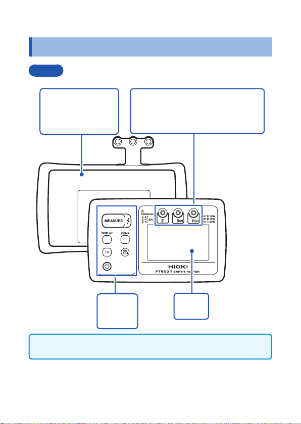
1.2 Parts Names and Functions
Front
Protector
Removed when
replacing the batteries.
(p. 24, p. 68)
Operation
buttons
(p. 17)
Please do not press the buttons of the device with a sharp object. It may
damage the device.
Measurement terminals
E Connected with the black cable.
S(P) Connected with the yellow cable.
H(C) Connected with the red cable.
Display
(p. 18)
15
Page 20
Parts Names and Functions
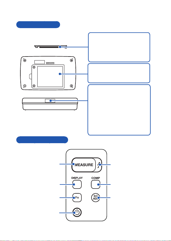
Rear and Sides
Battery cover (side view)
Operation Buttons
Waterproof seal
It needs to be replaced when
degraded.
Please contact your authorized
Hioki distributor.
Battery cover
Removed when replacing the
batteries. (p. 25)
Serial number label
Please do not remove the label
as it is needed for product control
such as product warranty etc.
(The serial number consists of 9
digits. The rst two (from the left)
indicate the year of manufacture,
and the next two indicate the
month of manufacture)
16
1
2
3
5
6
7
4
Page 21
Parts Names and Functions
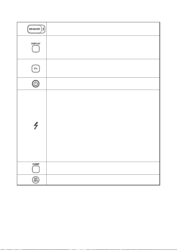
1
2
3
4
5
6
7
Start/stop for measuring earth resistance
• Displays the resistance of each earthing electrode.
(p. 39)
• Display switching (three-pole method, two-pole method)
• DC/AC switching (when measuring earth potential)
• Function switching (three-pole method, two-pole method)
• Unlocks the retained value and displays the current earth
potential value.
Power ON/OFF
Live wire warning LED
• For three-pole method
Blinks under any of the following conditions:
• A voltage of 30 V or higher is applied between the S(P)
and E terminals.
• A voltage of 85 V or higher is applied between the H(C)
and E terminals.
• A voltage of 85 V or higher is applied between the H(C)
and S(P) terminals.
• For two-pole method
Blinks when a voltage of 30 V or higher is applied
between the H(C) and E terminals.
• Lights up during earth resistance measurements.
Sets/cancels comparator setting (COMP lights up/goes off).
(p. 31)
Sets/cancels zero adjustment setting. (p. 35, p. 46)
17
Page 22
Parts Names and Functions
Display
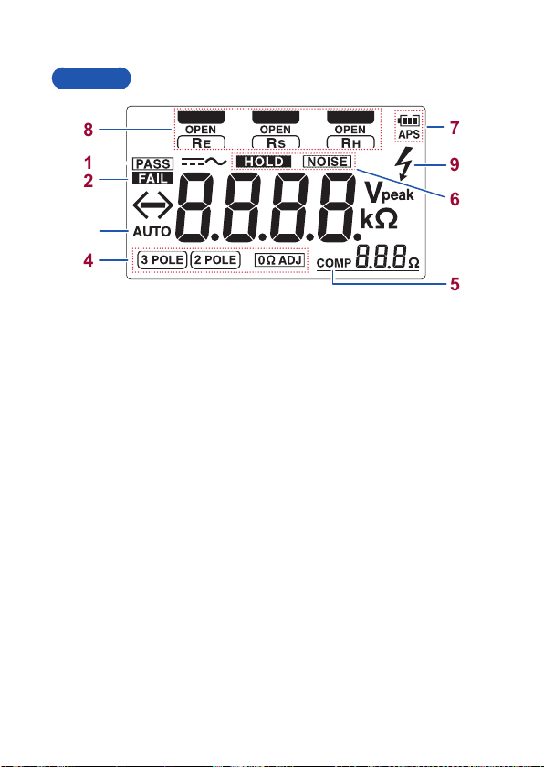
8
1
7
9
2
6
3
4
5
18
Page 23
Parts Names and Functions
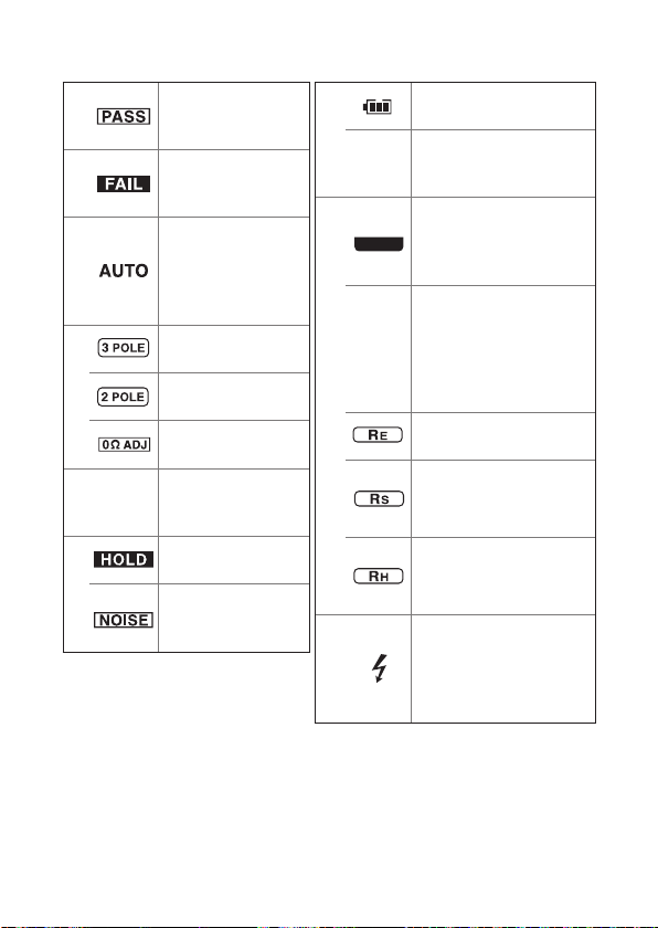
Comparator
1
2
3
4
5
6
comparison result
(PASS)
Comparator
comparison result
(FAIL)
Lights up when DC/
AC auto-detect
setting is enabled
for measuring earth
potential.
Three-pole method
(p. 33)
Two-pole method
(p. 44)
Zero adjustment
(p. 35, p. 46)
Displays when
COMP
comparator setting
is enabled. (p. 31)
Retention of the
measured value
Displays when earth
potential exceeds
allowable range.
7
8
9
See p. 73 for error display.
Displays the battery
level. (p. 27)
Displayed 30 sec. before
APS
auto-power-save function
is activated. (p. 56)
Indicates the terminal
to be connected with
measurement cable or
test lead.
Turns on when the
resistance of each
(auxiliary) earthing
OPEN
electrode is high or a
measurement cable is not
connected.
Earth resistance of
earthing electrode
Earth resistance of
auxiliary earthing
electrode S
Earth resistance of
auxiliary earthing
electrode H
Live wire warning
indicator
(Blinks during
earth resistance
measurements)
19
Page 24
How to Use Carrying Case
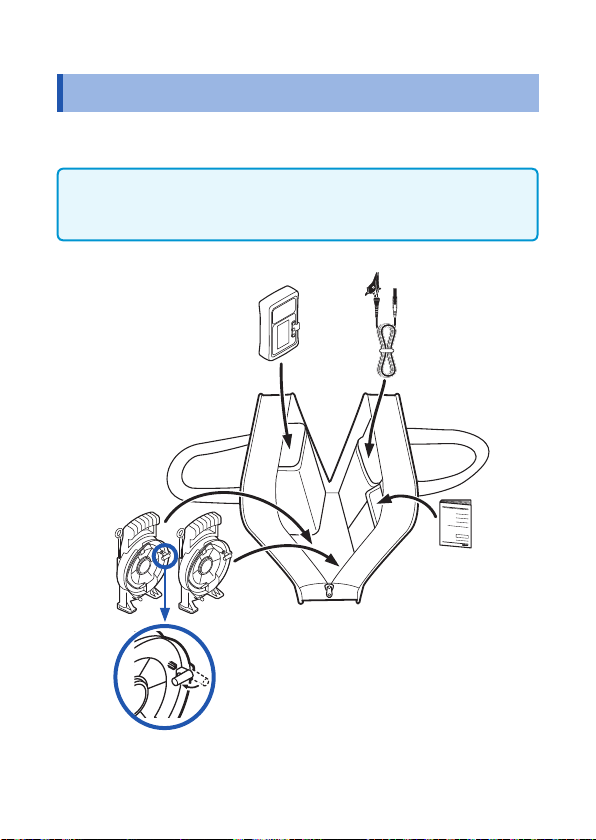
1.3 How to Use Carrying Case
Please store the device, winder and other accessories/options into
the C0106 Carrying Case as shown in the gure below.
• Please do not store commercially available pegs in this carrying
case as those have sharp tips. It may damage the case.
• Please do not wash the carrying case.
• Winder
• Auxiliary
Earthing Rod
20
Earth Tester
Please make sure to retract the
winder knob before storing it in the
carrying case.
Measurement
Cable (Black)
Instruction Manual
Page 25
How to Measure
2
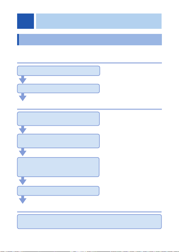
2.1 Measurement Workow
Before using the instrument, be sure to read “Usage Notes” (p.8).
Preparation
Insert the batteries. (p.25)
As necessary, have other
Perform the startup check. (p.29)
Measurement
Turn the power on and select the
measurement method.
optional items available and
ready.
Connect measurement cables or
leads to the measurement terminals.
Perform zero adjustment.
(three-pole method (p.35),
two-pole method (p.46))
Start the measurement.
test
End of the measurement
Turn the power off and remove measurement cables or test leads
from the measuring object.
21
Page 26
Measurement Workow
• This product should only be connected to the
secondary side of a breaker, so the breaker can
prevent an accident if a short circuit occurs.
Connections should never be made to the primary
side of a breaker, because unrestricted current ow
could cause a serious accident if a short circuit
occurs.
• Connect the test lead to the instrument rst, and
then to the active lines to be measured. To avoid
electric shock and short circuits, do not shortcircuit two wires to be measured by bringing the
metal part of the test lead's clip into contact with
them. Never touch the metal end of the clip.
To avoid electric shock, observe the following precautions.
• Prior to measurement, please make sure that the
earthing electrode has been disconnected from
the distribution system. The measurement cables
L9841, L9842-11, L9842-22, L9843-51 and L9843-52
are measurement cables with the maximum rated
voltage of 30 V (between input terminals and the
ground) and are designed to measure the earth
resistance of an earthing electrode disconnected
from the distribution system.
• Turn off all power before connecting cables and test
leads.
• Conrm that all connections of cables and test
leads are secure to the measurement terminals. The
increased resistance of loose connections can lead
to overheating and re.
DANGER
WARNING
22
Page 27

Measurement Workow
WARNING
• To prevent electric shock, conrm that the white
or red portion (insulation layer) inside the cable of
L9787 test lead and L9844 measurement cable are
not exposed. If a color inside the cable is exposed,
do not use the cable.
CAUTION
• To avoid damaging the cables and test leads, grasp the
connector, not the cable, when unplugging the cable.
23
Page 28

Attaching/Removing Protector
2.2 Attaching/Removing Protector
Attaching the protector
Tilt the device and slide it into the protector, and then push the
entire device into the protector.
Removing the protector
Hold it with both hands and push the one end of the protector down.
IMPORTANT
If the protector is removed, drop-proof (p.60) will be void.
24
Page 29

Inserting/Replacing Batteries
2.3 Inserting/Replacing Batteries
Before using the instrument, insert 4 LR6 alkaline batteries. Before
measurements, check that the battery level is sufcient. When the
battery charge is low, replace the batteries.
WARNING
• To avoid electric shock, turn off the power and
disconnect the cables and test leads before
replacing the batteries.
• To prevent instrument damage or electric shock,
use only the screws for securing the battery cover
in place that shipped with the product.
If you have lost any screw or nd that any screws
are damaged, please contact your Hioki distributor
for a replacement.
• Battery may explode if mistreated. Do not short-
circuit, disassemble or dispose of in re. Do not
recharge alkaline batteries. Handle and dispose of
batteries in accordance with local regulations.
• After replacing the batteries, replace the cover,
screws, and put on the protector before using the
instrument.
25
Page 30

Inserting/Replacing Batteries
CAUTION
Poor performance or damage from battery leakage could
result. Observe the cautions listed below.
• Do not mix new and old batteries, or different types of
batteries.
• Be careful to observe the battery polarity during
installation.
• Do not use batteries after their recommended expiry date.
• Do not allow used batteries to remain in the instrument.
• To avoid corrosion from battery leakage and/or damage
to the instrument, remove the batteries from the
instrument if it is to be kept in storage for an extended
period.
• If the battery level is low, mark blinks. To carry out
measurement, the batteries need to be replaced with new ones.
• After use, be sure to turn off the instrument.
• Although rechargeable batteries (nickel-hydride) can be
used for measurement, the battery level indicator will not be
accurately displayed.
• When replacing the batteries after cleaning, the replacement
should be carried out after the device has been completely dried.
• The operating temperature of the batteries included in the
shipment is -10°C to 45°C (14°F to 113°F). When using this
device outside this temperature range, use batteries that can
support such a low or high temperature range. (An example:
Lithium battery)
26
Page 31

Battery warning indicator
Fully charged.
As the battery charge diminishes, black charge bars disappear,
one by one, from the left of the battery indicator.
The battery voltage is low. Replace the batteries as soon as
possible.
(Blinks) The battery is exhausted. Replace the batteries.
Inserting/Replacing Batteries
27
Page 32

Inserting/Replacing Batteries
Rear
Battery Cover
Screwdriver
Have the following items
1
available and ready.
Phillips screwdriver
•
LR6 Alkaline battery × 4
•
Turn off the device and
2
remove the measurement
cables or test leads from
the device.
Remove the protector. (p.24)
3
Unscrew the screws of the
4
battery cover with a phillips
screwdriver.
Remove the battery cover.
5
Do not remove the
waterproof seal from the
battery cover.
When replacing the batteries,
6
all of the old batteries should
be removed.
Pay attention to the
7
polarities of the batteries
when inserting 4 new
batteries (LR6).
28
Reattach the battery cover
8
onto the device and tighten
the screws.
Attach the protector. (p.24)
9
Page 33

Inspection before Use
2.4 Inspection before Use
Before using the instrument, verify that it operates normally to ensure
that no damage occurred during storage or shipping. If you nd any
damage, contact your authorized Hioki distributor or reseller.
Check items Solution
Is the battery level sufcient? Check the battery level indicator on the upper
Is there any missing segment
in the display items?
Is there any damage or
crack in the device?
Is there any foreign material
(sand etc.) inside the
measurement terminals?
Is there any damage or
exposed internal white part
or metal in the coating of
measurement cable or test
lead?
right corner while the power has been turned
on. If
Replace the batteries with new ones. (p.25)
Check by activating the LCD all-on display.
(p.56)
If there is a missing segment, the device
needs to be repaired.
Conduct visual checking.
If damage is found, the device should not
be used and needs to be repaired as it can
cause electric shock.
Remove all foreign materials if any. If it cannot
be removed, the device needs to be repaired.
If damage is found, it should not be used and
needs to be replaced as it can cause electric
shock.
is blinking, the battery level is low.
29
Page 34

Inspection before Use
Check items Solution
Check for open circuit in
measurement cable or test
lead in the following method:
1. • For three-pole method
Press Fn button to
display
• For two-pole metho
Press Fn button to
display
2. Connect measurement
cables or test leads to
the device and shortcircuit their tips.
3. Press MEASURE button
to check that approx. 0
is indicated.
Ω
.
.
If not indicating approx. 0
• The measurement cables or test leads have
not been fully inserted.
→Fully insert the leads.
• The measurement cables or test leads may
have an open circuit.
→Replace it with another lead that is
d
specied by Hioki.
If the symptom persists even after the
measurement cables or test leads are
replaced, the device may have a failure.
The device needs to be repaired.
Ω
30
Page 35

Setting Up Comparator (PASS/FAIL Test)
2.5 Setting Up Comparator (PASS/FAIL Test)
The device has a comparator function, which can indicate PASS or
FAIL with the display indicator and beep. The earth resistance can
be measured without setting up the comparator.
The comparator function operates as follows:
Comparison result Display Buzzer sound
Measured value
value (PASS)
Measured value > Reference
value (FAIL)
The comparison reference value can be chosen from the reference
values in the following table.
1 2 3 4 5
6 7 8 9
10 20 30 40 50
60 70 80 90
100* 200 300 400 500 OFF
Reference
Reference value (Ω)
Intermittent
Continuous
*Default
31
Page 36

Setting Up Comparator (PASS/FAIL Test)
How to set up comparator
Press Fn button to set to
1
(three-pole method), or
(two-pole method).
Press COMP button.
2,3
1
3
2
blinks, and the resistance for the
comparison reference appears.
Press COMP button again and then
choose a comparison reference.
If there is no operation for approx. 2 seconds
after the desired comparison reference has
been chosen, the comparator is enabled
and
The comparator setting is saved even
after the power is turned off.
lights up in the display.
How to disable comparator
Press COMP button while the comparator has been enabled.
1
2
blinks.
Press COMP button and then select [OFF].
If there is no operation for approx. 2 seconds, the comparator is
disabled.
32
Page 37

Precise Measurement for Earth Resistance
(Precise Measurement Method, Three-pole Method)
2.6 Precise Measurement for Earth Resistance (Precise Measurement Method, Three-pole Method)
WARNING
This device can output a voltage of approx. 30 V.
Although the device has a dust-proof, jet-proof and
water-proof structure, the device should always be
dried before using it for measurement so as to avoid
electric shock.
CAUTION
Do not connect the test leads if any foreign material
remains inside. It may cause failure.
There are two types of measurement method for earth resistance:
precision measurement method (three-pole method) and
simplied measurement method (two-pole method), and the
precision measurement method (three-pole method) is the basic
measurement method for earth resistance.
The simplied measurement method is used when measurement
cannot be performed by the precision measurement method.
The precision measurement is performed by inserting two auxiliary
earthing rods into the ground as shown in the gure on p.38.
33
Page 38

Precise Measurement for Earth Resistance
(Precise Measurement Method, Three-pole Method)
Measurement of large-scale earthing electrodes
When measuring a large-scale earthing electrode such as a mesh earthing
electrode, ring earthing electrode, or earthing electrode provided by a
large building structure, it cannot be accurately measured since the H(C)
electrode and S(P) electrode come inside the earth resistance area of E
electrode.
If long cables are used to avoid the H(C) electrode and S(P) electrode
getting inside the earth resistance area, accurate measurement cannot be
carried out as it is signicantly affected by noise.
Generally, measurement of large-scale earthing electrode requires a large
measurement current of approx. 20 A. Use measuring instrument designed
for measuring large-scale earthing electrodes for this measurement. (No
measuring instrument available for this purpose from Hioki)
34
Page 39

Precise Measurement for Earth Resistance
(Precise Measurement Method, Three-pole Method)
Performing zero adjustment
Always perform zero adjustment prior to measurement.
Remove the cover that protects the
1
2
7
3
6
8
5
1
measurement terminals.
Make sure that no sand, gravels
2
or small stones remain inside the
measurement terminals.
Connect black, yellow and red
3
measurement cables respectively to E,
S(P) and H(C) terminals of the device.
Short-circuit the tips of the three
4
measurement cables.
Press the button to turn it on.
5
Press Fn button to display
6
(three-pole method).
Earth potential appears on the display.
Press MEASURE button.
7
4
A measured value of approx. 0 Ω appears in
approx. 8 seconds, and
When OPEN appears below the measurement
terminal (
not have been connected to a measurement
terminal, or the cable may have an open
circuit.
cable check with a tester etc.
), the measurement cable may
Check the connection and perform
lights up.
Press 0ΩADJ button.
8
adjustment is completed.
lights up and then zero
35
Page 40

Precise Measurement for Earth Resistance
(Precise Measurement Method, Three-pole Method)
If the measured value exceeds 3 Ω, [Err 1] appears and zero adjustment
will not be executed. Zero adjustment settings will be saved even if the
power is turned off.
How to disable zero adjustment
Hold down
Ω
0
ADJ button for at least one second, while is on.
Connecting measurement cables
WARNING
• The maximum rated voltage between input terminals
and the ground is as follows;
(CAT II): 300 V rms
(CAT III): 150 V rms
(CAT IV): 100 V rms
Attempting to measure voltages exceeding this
level with respect to ground could damage the
instrument and result in personal injury.
• To avoid electric shock, be careful to avoid shorting
live lines with the test leads.
36
Page 41

Precise Measurement for Earth Resistance
(Precise Measurement Method, Three-pole Method)
CAUTION
• To prevent cable damage, do not step on cables or
pinch them between other objects. Do not bend or pull
on cables at their base.
• The ends of the auxiliary earthing rod are sharp. Be
careful to avoid injury.
• To ensure safe operation, use only the accessory
cables.
• The cable is hardened under the 0 degree or colder
environment. Do not bend or pull it to avoid tearing its
shield or cutting cable.
• If the cable melts, the metal part may be exposed
and can pose a hazard. Do not touch the area that is
generating heat.
Red
Yellow
Black
5 3
Auxiliary
Earthing
Electrode
H
10 m 10 m
Auxiliary
Earthing
Electrode
S
1
Earthing
Electrode
E
E
HS
37
Page 42

Precise Measurement for Earth Resistance
(Precise Measurement Method, Three-pole Method)
Use the measurement cable (black)
1
to connect between earthing
electrode and E terminal.
Carry two winders along to the
2
measuring location while pulling
out the measurement cables.
2
At the location where the
3
measurement cable (yellow)
has been fully pulled out, insert
the auxiliary earthing rod into
the ground and connect the
measurement cable (yellow).
Carry the winder (measurement
4
cable: red) along the straight line
to a further distance between the
earthing electrode E and auxiliary
earthing electrode S while pulling
out the measurement cable.
At the location where the
5
measurement cable (red) has been
fully pulled out, insert the auxiliary
earthing rod into the ground and
connect the measurement cable (red).
• Insert the auxiliary earthing rods into a moist layer in the
ground. Since this device can accept a large resistance of
auxiliary earthing electrode, the auxiliary earthing rods do not
need to be inserted unnecessarily deep into the ground.
• For accurate measurement, the distance between E-S-H needs
to be approx. 5 m. The measurement cables (yellow) and (red)
should be positioned approx. 10 cm away from each other.
Make sure the cables do not tangle or overlap together.
38
Page 43

Precise Measurement for Earth Resistance
(Precise Measurement Method, Three-pole Method)
Measuring earth resistance
Press the button to turn it on.
1
3
2
1
When NOISE Appears
If the earth potential is high (10 V rms or 14.3 Vpk or higher),
and the earth potential peak value appears on the display.
When is on, or when (live wire warning LED) is blinking,
it is not possible to measure earth resistance.
Since leak current is owing into the earthing electrode, rst
disconnect any electric equipment connected to the earthing
electrode and then press MEASURE button again.
Press Fn button to display
2
(three-pole method).
Earth potential appears on the display.
Press MEASURE button so that the
3
device automatically executes the
earth potential check→auxiliary earth
resistance check→earth resistance
measurement in sequence.
The measurements will be completed in
approx. 8 seconds, and then the measured
value appears and
Check the measured value.
4
lights up.
39
Page 44

Precise Measurement for Earth Resistance
(Precise Measurement Method, Three-pole Method)
• This device automatically detects AC/DC ( / ) of the
earth potential.
If AC/DC needs to be switched, it can be switched by pressing
DISPLAY button while the current earth potential has been
displayed.
• To check earth potential
After measurement of earth resistance, press DISPLAY button
while is lit up so that the earth potential will be displayed.
When is lit up, press Fn button so that the retained
value is unlocked and the current earth potential will be
displayed.
When OPEN Appears
This device automatically check whether or not each earth
resistance is within the allowable range by measuring the earth
resistance of the auxiliary earthing rod prior to measuring the
resistance of the earthing electrode E.
If the earth resistance of the auxiliary earthing electrode exceeds
the allowable range, OPEN appears below the measurement
terminal that exceeds the allowable range and the earth resistance
of the earthing electrode E will not be measured.
Countermeasures when OPEN appears
Take the following actions for the auxiliary earthing rod connected
with the measurement terminal for which OPEN appears.
• Pour water
• Stick in deeper
• Insert the auxiliary earthing rod into another location
• If the clip connecting point is dirty, wipe and clean the auxiliary
earthing rod with a soft cloth.
40
Page 45

Precise Measurement for Earth Resistance
(Precise Measurement Method, Three-pole Method)
DISPLAY button allows to display the earth resistance and earth
potential of each earthing electrode.
Earth resistance of earthing electrode E
Earth resistance of auxiliary earthing electrode S
Earth resistance of auxiliary earthing electrode H
V
Earth potential
When the resistance (RH) of auxiliary earthing electrode exceeds
5 kΩ, the display range becomes the range of 200 Ω without
displaying the digit of 0.01 Ω even though the resistance of
earthing electrode is 20 Ω or less. The following table shows
examples.
If the digit of 0.01 Ω is required, pour some water over the
auxiliary earthing rod (H) to reduce the earth resistance to 5 kΩ or
less.
Resistance RH of
auxiliary earthing
electrode H
0 to 5 k
Ω
to 50 k
5 k
Ω
Ω
Example of indicated
value (1)
When 9.52
measured
9.52 Ω (Range: 20 Ω) 13.48 Ω (Range: 20 Ω)
9.5 Ω (Range: 200 Ω) 13.5 Ω (Range: 200 Ω)
is
Ω
Example of indicated
value (2)
When 13.48
measured
is
Ω
41
Page 46

Precise Measurement for Earth Resistance
(Precise Measurement Method, Three-pole Method)
Stowing
Press the button to turn it off.
1
Remove the measurement
2
cables from the measurement
terminals and t the cover of the
measurement terminal.
Remove the measurement cables
3
from the auxiliary earthing rods
and pull out the auxiliary earthing
rods without bending them.
(See p.55 for how to pull out.)
Rewind the measurement cables
4
(red, yellow) with the respective
winders and stow the winders in
the carrying case with the auxiliary
earthing rods inserted into the
winder's holders.
Remove the measurement cable
5
(black) from the earthing electrode
and fold it, and then stow it into
the carrying case. (p.20)
Always t the cover of the measurement terminals immediately
after use. Any foreign object entering the measurement terminal
may cause a failure.
42
Page 47

Precise Measurement for Earth Resistance
(Precise Measurement Method, Three-pole Method)
Measurement on concrete
Since concrete is conductive, auxiliary
earthing electrodes can be installed on
concrete.
Place an auxiliary earthing rod on
concrete and pour water over it, or
cover the auxiliary earthing rod with a
wet rag to form an auxiliary earthing
electrode.
If the earth resistance of the auxiliary earthing electrode is not reduced
by the above methods, place the optional 9050 earth net on concrete and
then position the auxiliary earthing rod on the earth net and pour water
over it. Before measurement, allow some time for the water to well soak
into the concrete.
As an alternative to the earth net, a metal plate or aluminum foil etc. may
be used. However, the earth net will provide better reduction in the earth
resistance of auxiliary earthing electrode.
Since asphalt is insulator, it is generally not possible to install the auxiliary
earthing electrode on asphalt. However, measurement may be possible on
asphalt that has water permeability.
9050 Earth Nets
43
Page 48

Simplied Measurement for Earth Resistance
(Simplied Measurement Method, Two-pole Method)
2.7 Simplied Measurement for Earth
Resistance
(Simplied Measurement Method,
Two-pole Method)
DANGER
• Use the neutral side (ground side) of the commercial
power supply for this measurement. Prior to
connection, use a voltage detector etc. to make sure
that it is going to be connected with the neutral side
and take caution for electric shock.
• This device can be connected to the neutral side of
an outlet with a voltage-to-ground of 300 V or less,
or to the wire on the neutral side of the breaker's
secondary side with a voltage-to-ground of 150 V or
less. Do not connect with anything other than those
specied above. It can be hazardous.
WARNING
• Use the optional test lead L9787 for simplied
measurement for safety. Connecting the
measurement cables L9841, L9842-11, L9842-22,
L9843-51 and L9843-52 to a commercial power
supply may cause electric shock.
• This device can output a voltage of approx. 30 V.
Although the device has a dust-proof, jet-proof and
water-proof structure, the device should always
be dried before using it for measurement so as to
avoid electric shock.
44
Page 49

Simplied Measurement for Earth Resistance
(Simplied Measurement Method, Two-pole Method)
CAUTION
• When the device is set to two-pole method, even if it
is connected to the earth side of a commercial power
supply, it will not trigger the earth leakage breaker since
the measurement current is suppressed to 4 mA or less.
However, do not use this method for measurement at
a location where an earth leakage breaker or leakage
relay with the current sensitivity of less than 10 mA has
been installed, since such an earth leakage breaker or
leakage relay may be triggered.
• The simplied measurement function of this device is
a function for measuring earth resistance with small
inductance component.
Therefore, a resister connected in series with
inductance component of 3 mH or more may not be
accurately measured.
• Removable sleeves are attached to the metal pins at
the ends of the test leads. To prevent a short circuit
accident, be sure to use the test leads with the sleeves
attached when performing measurements in the CAT
III measurement category. For the measurement
categories, see “Measurement categories” (p.7).
• If the sleeves are inadvertently removed during
measurement, stop the measurement.
• When carrying out measurements with the sleeves in
place, be careful to avoid damaging the sleeves. If the
cover cap accidentally comes off during measurement,
it should be handled carefully to avoid electric shock.
• Since the tip of the metal pin is sharp, care needs to be
taken to avoid injury.
• L9787 is a test lead specically designed for indoor use.
Do not use it outdoor.
45
Page 50

Simplied Measurement for Earth Resistance
(Simplied Measurement Method, Two-pole Method)
Removing and attaching the sleeves of L9787 Test lead
• Removing the sleeves
Hold the bottom of the sleeves and pull the sleeves off.
Safely store the removed sleeves so as not to lose them.
• Attaching the sleeves
Insert the metal pins of the test leads into the holes of the
sleeves, and rmly push them all the way in.
What is simplied measurement method (two-pole method)?
Simplied measurement method (two-pole method) is a measurement
method to check the earth resistance of the equipment earthing with an earth
system called TT method.
In case of not being able to insert an auxiliary earthing rod, the earth
resistance is obtained with use of an existing low earthing resistor as an
auxiliary electrode.
In this method, the measured value is the sum (Rx+Ro) of the earth
resistances of the measuring object and existing earthing resistor,
according to the measurement principle. Therefore, the earth resistance
of the existing earthing resistor used needs to be lower than that of the
earthing electrode of the measuring object.
In the simplied measurement method, the resistance of the earthing
element used is added to the measurement result.
It is very difcult to measure 10
or less in the simplied method.
Ω
Performing zero adjustment
The range that this device can provide zero adjustment for is 3 Ω or less. If
the measured value exceeds 3
not be executed.
, [Err 1] appears and zero adjustment will
Ω
46
Page 51

Simplied Measurement for Earth Resistance
(Simplied Measurement Method, Two-pole Method)
Remove the cover of the
1
6
4
2
E
H(C)
7
3
1
measurement terminals.
Connect the E terminal and H(C)
2
terminal of this device respectively
with the L9787 test lead (black)
and L9787 test lead (red).
Press the button to turn it on.
3
Press Fn button to display
4
(two-pole method).
A measured value (approx. 0 V) of the earth
potential appears
Connect (short-circuit) the tips of
5
test leads.
Press MEASURE button.
6
5
A measured value of approx. 0 Ω appears in
approx. 3 seconds, and
When appears below the
measurement terminal, a test lead may not
have been connected to the measurement
terminal, or the lead may have an open
circuit. Check the connection and perform
cable check with a tester etc.
.
lights up.
Pressing 0ΩADJ button will turn
7
adjustment.
How to disable zero adjustment
Hold down 0
ADJ button while
Ω
on and complete zero
is on.
47
Page 52

Simplied Measurement for Earth Resistance
(Simplied Measurement Method, Two-pole Method)
Connecting test leads
WARNING
• Do not use this device for measuring the voltage of
commercial power supply.
• If there is a large voltage on the neutral side,
(live wire warning LED) blinks and beep sound goes
off. Immediately remove the test leads from the
commercial power supply.
• If the earth potential is high, attention needs to be
paid for the risk of electric shock.
• To prevent an electric shock, do not exceed the
lower of the ratings shown on the instrument and
test leads.
The gure below shows an example of connection in the case of using
a commercial power supply that is grounded on its N (neutral) side.
Pole-mounted
Transformer
48
Ro
Outdoor
Rx
Home Distribution Panel
Indoor
Master
Breaker
Central Earth
Terminal
Earth Leakage
Breaker
Branch Breaker
Page 53

Simplied Measurement for Earth Resistance
(Simplied Measurement Method, Two-pole Method)
Use a voltage detector etc. to make
1
sure that there is no voltage on
the N (neutral) side of commercial
power supply.
Press the
2
Press Fn button to display
3
4
5
E
H(C)
3
2
(two-pole method).
When (three-pole method) is
chosen, the earth leakage breaker etc. may
be triggered due to its large measurement
current.
Connect the L9787 test lead (black)
4
with the earthing electrode of
measuring object.
Connect the L9787 test lead (red) with
5
the N (neutral) side of commercial
power supply.
Earth potential appears on the display.
button to turn it on.
49
Page 54

Simplied Measurement for Earth Resistance
(Simplied Measurement Method, Two-pole Method)
• When appears, a large earth potential (10 V rms or 14.3 Vpk or
higher) exists between the earth and the N (neutral) side of commercial
power supply. A large leak current may be flowing through the earthing
electrode of the measuring object or through the earthing element of the
commercial power supply used for measurement.
insulation resistance test or leakage current test etc. In addition, disconnect
any electric equipment from the earthing electrode.
• This device automatically detects AC/DC of the earth potential.
• If AC/DC needs to be switched during earth potential measurement, it
can
be switched by pressing
• After measurement of earth resistance, press DISPLAY button while
is lit up so that the earth potential will be displayed.
When
unlocked and the current earth potential will be displayed.
• When
not possible to execute earth resistance measurement.
is lit up, press Fn button so that the retained value is
is on, or when (live wire warning LED) is blinking, it is
DISPLAY
button.
Therefore, conduct an
50
Page 55

Simplied Measurement for Earth Resistance
(Simplied Measurement Method, Two-pole Method)
Measuring earth resistance
Press MEASURE button so that the device automatically executes
the following measurements in sequence. The measured value
appears in approx. 3 seconds and lights up.
Check earth potential.
1
Check whether or not the peak value of the earth potential
is within the allowable range.
Measure earth resistance.
2
Measure the sum (Rx + Ro) of the earth resistance of
earthing electrode and the earth resistance on the neutral
side of commercial power supply.
Stowing
Press the button to turn it off for safety.
1
Remove the test leads from the measurement terminals and
2
t the cover of the measurement terminal. (p.42)
Fold the test leads together and stow it into the carrying case.
3
51
Page 56

Cautions and Tips for Measurement
2.8 Cautions and Tips for Measurement
Distance between earthing electrodes
When the distance between E-H(C) is I m as shown in Figure (a), if
the resistance of the earthing element E is measured while changing
the distance x m between the electrodes E-S(P), measurement
results such as shown in (b) are obtained.
Therefore, its error becomes greater as the location of the auxiliary
earthing rod S(P) moves closer to the earthing element E or
auxiliary earthing rod H(C).
In addition, if the distance between the electrodes E-H(C) is short,
the measurement error is greater as the earth resistance under test
(Rx) and the earth resistance of auxiliary earthing rod (Rc) cannot
be separated from each other.
If earthing is provided by a building structure etc. in a large area, the
resistance area indicated in (a) becomes very wide.
In order to carry out accurate measurement, the auxiliary earthing
rods (S(P) and H(C)) need to be installed at a location well away
from the earthing element (Rx).
As to conrm the above, carry out measurements at several
locations while moving the location of the auxiliary earthing rod S(P)
from the earthing element (Rx) to the auxiliary earthing rod H(C)
and check whether or not there is an almost at section shown in (b)
in the measured resistance even though the auxiliary earthing rod
S(P) has been moved.
If no at section is seen, the measurement distance is insufcient.
Move the installation locations of the auxiliary earthing rods (S(P)
and H(C)) to further locations.
52
Page 57

Cautions and Tips for Measurement
Measured Value
Ground Surface
S(P)
Resistance
Area of E
Electrode
The distance between E-H(C) of this device can be up to 50 m by using
the optional L9843-51 and L9843-52. In principle, it is possible to carry
out measurement even if the distance is more than 50 m. However, the
measurement result cannot be guaranteed.
Resistance
Area of H(C)
Electrode
Flat Section
Location to install auxiliary earthing rod
It is ideal to install the auxiliary earthing rod S(P) at the middle point
of the straight line between the earthing electrode E and auxiliary
earthing rod H(C).
However, if installation is not possible due to an obstacle etc.,
the measurement error can be reduced by installing the auxiliary
earthing rod (S(P)) within 29° from the straight line between the
earthing electrode E and auxiliary earthing rod H(C), wherein the
location should be outside the radius of 5 m from the earthing
element E and auxiliary earthing rod H(C) as shown in the gure.
5 m
E
S(P) H(C)
29°
5 m
53
Page 58

Cautions and Tips for Measurement
How to insert / pull out auxiliary earthing rod
How to Insert
The accessory auxiliary earthing rods are suitable for providing
auxiliary earthing electrodes and are designed for thickness and
hardness that allow insertion into a general ground by hand. Since it
is skinnier than conventional models, it can be inserted into a small
gap.
When inserting the rod, wear gloves and insert it perpendicular to
the ground surface.
If the ground is too hard for inserting by hand, use a hammer to
perpendicularly drive into the ground. Hammering the auxiliary
earthing rod too hard may result in bending it. In case of not going
into the ground with gentle taps, use the optional 9050 earth net for
measurement.
54
Page 59

How to Pull Out
• Hold the loop part of the auxiliary
earthing rod and pull it out while
turning it.
• If it does not come out by hand, put
a hard metal bar etc. (other than
auxiliary earthing rod) through the
loop part of the auxiliary earthing rod
and pull the auxiliary earthing rod
while turning it.
If pulling the auxiliary earthing rod
with another auxiliary earthing rod
put through the loop, it will result in
bending it.
• Do not apply force to the auxiliary
earthing rod from the side as it may
result in bending the auxiliary earthing
rod.
Cautions and Tips for Measurement
55
Page 60

Auto Power Save (Power-saving Function)
2.9 Auto Power Save (Power-saving Function)
Approx. 10 min after the last operation or the last time (live wire
warning LED) turns on or blinks, the auto power save becomes
active and the screen turns off.
How to recover from auto power save
Press the
How to disable auto power save
Turn the power on while pressing 0
The settings of an disabled auto power save will not be saved
when the power is turned off.
button to turn the screen on.
ADJ button.
Ω
2.10 Activating the LCD All-on Display
Turn the power on while pressing DISPLAY button.
1
If any button is pressed, its normal measurement screen
2
will appear.
56
Page 61

Displaying the Serial number
2.11 Displaying the Serial number
Turn the power on while pressing Fn button.
The rst 4 digits and the last 5 digits of the serial number (9 digits)
appear alternately.
If any button is pressed, its normal measurement screen will appear.
First 4 digits
(Example of a serial number: 140756789)
The serial number consists of 9 digits. The rst two (from the left) indicate the
year of manufacture, and the next two indicate the month of manufacture.
Last 5 digits
57
Page 62

Displaying the Serial number
58
Page 63

Specication
3
3.1 General Specication
Product warranty period 3 years
Guaranteed accuracy
period
Nominal range of use
Operating temperature
and humidity
Position
Power supply voltage
Earth potential
Resistance of auxiliary
earthing electrode
External magnetic eld
Storage temperature and
humidity
Operating environment
(scope of application)
Power source LR6 Alkaline battery × 4
Rated power supply
voltage
1 year
-25°C to 40°C (-13°F to 104°F): 80% RH or
less (non-condensing)
40°C to 45°C (104°F to 113°F): 60% RH or
less (non-condensing)
45°C to 50°C (113°F to 122°F): 50% RH or
less (non-condensing)
50°C to 55°C (122°F to 131°F): 40% RH or
less (non-condensing)
55°C to 60°C (131°F to 140°F): 30% RH or
less (non-condensing)
60°C to 65°C (140°F to 149°F): 25% RH or
less (non-condensing)
Level ±90°
Available effective battery voltage
Refer to: “Allowable earth potential” (p.63)
Refer to: “Allowable resistance of auxiliary
earthing electrode” (p.62)
400 A/m or less, DC and frequency 50/60 Hz
-25°C to 65°C (-13°F to 149°F): 80% RH or
less (non-condensing)
Indoor, outdoor (excluding farmland*), pollution
degree 3, altitude up to 2000 m (6,562 ft.)
According to the requirements regarding the
*
regulations for open-circuit voltage in EN 61557-5
1.5 V DC × 4
59
Page 64

General Specication
Maximum rated power 3 VA
Available effective battery
voltage
Possible number of
measurements
IP protection code IP65/IP67
Drop-proof 1 m above concrete (with protector attached)
Maximum rated voltage
between input terminals
and the ground
Withstand voltage 3510 V, 50/60 Hz,
Dimensions Approx. 185 W × 111 H × 44 D mm (7.28” W ×
Mass Approx. 570 g (20.1 oz.) (including batteries
Accessories
Options Refer to: “Options (sold separately)” (p.2)
Applicable standards Safety
4.5 V ±0.19 V to 6.8 V
400 times (measurement conditions: three-pole
method, auxiliary earthing electrode resistance
, measure 10 Ω with the range of 20 Ω,
100
Ω
measure at 10 seconds interval)
(EN 60529)
100 V AC/DC (measurement category IV)
150 V AC/DC (measurement category III)
300 V AC/DC (measurement category II)
anticipated transient overvoltage 2500 V
between measurement terminals (together)
and case, for 15 seconds, sensed current 1 mA
4.37” H × 1.73” D)
(including protector, excluding terminal covers)
and protector, excluding other accessories)
Refer to: “Verifying Package Contents” (p.1)
Device : EN 61010
Measuring circuit : EN 61010
EMC : EN 61326
Earth tester : EN 61557
60
Page 65

Measurement Function/Performance
3.2 Measurement Function/Performance
Temperature and humidity: 23°C ± 5°C (73°F ± 9°F), 80% RH or less
Measurement of earth resistance
(auxiliary earthing electrode resistance 100 Ω±5%, earth potential 0 V)
RE: Earth resistance of measuring object, RH: Earth resistance of H
Operation
system
Measurement
system
Output voltage AC without DC component
Open-circuit
voltage
Measurement
current
Measurement
current
waveform
Measuring
frequency
Measuring time Three-pole method: Within 8 seconds
electrode, R
Voltage application, measurement of voltage and current
(effective resistance is measured by synchronous
detection)
Two-pole method / three-pole method, switchable
30 V rms or less and 42.43 Vpk or less
Three-pole method: 25 mA rms or less
Two-pole method: 4 mA rms or less
Sine wave
128 Hz ±2 Hz
Two-pole method: Within 3 seconds
: Earth resistance of S electrode
S
61
Page 66

Measurement Function/Performance
Range
conguration
(auto range)
Effect of
positioning (
E
Effect of supply
E
voltage (
)
2
Effect of
temperature
*5
E
)
(
3
Effect of earth
E
potential (
)
4
Applied
(RE and
RH)
*1
R
E
R
H
Display range
conditions
Display range
Resolution
Accuracy
3-pole 0.01
2-pole ― 1
*3
(specic uncertainty A)
Allowable
resistance of
auxiliary earthing
electrode
Operation
R
H
R
S
±30% rdg. (applied to three-pole
uncertainty
Guaranteed range
of operation
uncertainty
Not applicable due to digital type
)
1
*4
Accuracy × 0.5 and within accuracy
Accuracy × 1.0 (-10
°C to 50°C)
Accuracy × 2.0 (-25°C to -10
50 Hz, 60 Hz
DC, 16 2/3 Hz,
400 Hz
0 to 3 V Accuracy × 1.0
3 to 10 V Accuracy × 2.0
0 to 3 V Accuracy × 1.0
*2
20
20 Ω or
less
5 kΩ or
less
0 to
20.00
Ω
Ω
Ω
200 Ω2000
200 Ω or
less
50 k
Ω
less
0 to
200.0
0.1
Ω
±1.5 %
rdg.
8 dgt.
±
5 k
5 k
5.00 to 2000
°C, 50°C to 65°C)
±1.5 % rdg.
Ω
Ω
method)
or
Ω
Ω
±4 dgt.
50 k
50 k
Ω
200 Ω to
or less
2 k
Ω
50 kΩ or
less
200 to
2000
1
Ω
1
Ω
Ω
Ω
Ω
Ω
62
Page 67

Measurement Function/Performance
Allowable earth
potential
Effect of the
resistance
of auxiliary
earthing
E
electrode (
)
5
Effect of system
E
frequency (
)
7
Effect of system
E
voltage (
)
8
Effect of
external
magnetic eld
Earth resistance
of auxiliary
earthing
electrode autocheck
(auto-check
after start of
measurement)
Auto-check for
earth potential
*6
(auto-check
after start of
measurement)
Overload
protection
Effect of earth
capacity (twopole method)
10 V rms (DC or sine wave)
Either R
or RS electrode Variable value
H
or less Accuracy × 1.0
10 k
Ω
Above 10 k
to 50 k
Ω
Ω
Accuracy × 2.0
Not applicable
Not applicable
Accuracy × 0.5
Display range
Maximum display
value
Resolution 10 Ω0.1 k
1000 Ω10 kΩ100 kΩ200 k
1000 Ω10.0 kΩ100 kΩ200 k
1 k
Ω
Ω
Accuracy Not specied
Display range 42 Vpk
Maximum display
value
42.0 Vpk
Accuracy ±2.3 % rdg.±8 dgt.
360 V AC (for 1 min, between each terminal)
360 V DC (for 1 min, between each terminal)
Up to 10 nF Within accuracy specication
Above 10 nF to
500 nF
Accuracy × 2.0
Above 500 nF Not specied
10 k
Ω
Ω
Ω
63
Page 68

Measurement Function/Performance
Zero adjustment
allowable range
*1 Automatically select the minimum display range that can meet both R
and R
*2 Three-pole method only.
*3 Applied after zero adjustment, ±0.3
(with use of L9481).
*4 It shall be the range in which the operation uncertainty within ±30% is
guaranteed; applied to three-pole method.
*5 Applied in the range excluding 18 to 28°C.
*6 Function to check whether or not the peak of earth potential is within the
allowable range; no AC coupling; display the peak value (peak on + side).
values.
H
3
or less
Ω
is added before zero adjustment
Ω
E
Earth potential measurement
DC/AC
auto-detection
range
Measurement
system
Terminal
for voltage
measurement
Overload
protection
Display refresh
interval
Input resistance 4 M
Response time
0.3 V DC ± 0.2 V or higher is detected as DC
Manual switching function provided
Pulsating ow with superimposed AC component that
periodically zero-crosses is detected as AC
Average value rectication effective value indication
Three-pole method: Between S terminal (+) ― E terminal (-)
Two-pole method: Between H terminal (+) ― E terminal (-)
360 V AC for 1 min
360 V DC for 1 min
Within 1 second
or higher (DC / 50 Hz / 60 Hz)
Ω
Within 2 seconds (when input voltage is changed from 0 V
to 30 V)
64
Page 69

Measurement Function/Performance
Effect of
temperature
Range
conguration
Accuracy × 1.0 (-10°C to 50°C) applied in the range
excluding 18 to 28°C
Accuracy × 2.0 (-25°C to -10°C, 50°C to 65°C)
Display range 30 V rms
Maximum
display value
Resolution 0.1 V
Accuracy
50 Hz/ 60 Hz ±2.3 % rdg.±8 dgt.
30.0 V rms
DC ±1.3 % rdg.±4 dgt.
65
Page 70

Measurement Function/Performance
66
Page 71

Maintenance and Service
4
4.1 Repair, Inspection, and Cleaning
DANGER
Customers are not allowed to modify, disassemble, or
repair the instrument.
Doing so may cause re, electric shock, or injury.
Calibrations
IMPORTANT
Periodic calibration is necessary in order to ensure that the
instrument provides correct measurement results of the specied
accuracy.
The calibration frequency varies depending on the status of the
instrument or installation environment. We recommend that the
calibration frequency is determined in accordance with the status of
the instrument or installation environment and that you request that
calibration be performed periodically.
Cleaning
• To clean the instrument, wipe it gently with a soft cloth moistened
with water or mild detergent.
When rinsing with water, make sure that the battery cover has
been attached. Make sure that the protector has been removed
and rinse with room-temperature water.
• After cleaning, thoroughly wipe off water of the device and
protector. Completely dry them before putting the protector on.
• Rinse with room-temperature water. If rinsing with hot water, the
waterproof performance may be impaired.
• Do not put water while the battery cover has been taken off. It
may cause failure due to water intrusion.
67
Page 72

Repair, Inspection, and Cleaning
• When replacing the batteries after cleaning, the replacement
should be carried out after the device has been completely dried.
• This device is waterproof to a water depth of 1 m for 30 min. Do
not soak and wash the device. Do not soak the device into hot
water.
• Do not wash the device with a washing machine.
• Do not use any electronic appliance such as a dryer or microwave
for drying this device.
•
Wipe the LCD gently with a soft, dry cloth.
IMPORTANT
Never use solvents such as benzene, alcohol, acetone, ether,
ketones, thinners or gasoline, as they can deform and discolor the
case.
If the instrument is not to be used for an extended
period of time
IMPORTANT
To avoid corrosion from battery leakage and/or damage to the
instrument, remove the batteries from the instrument if it is to be
kept in storage for an extended period.
Disposal
Handle and dispose of the instrument in accordance with local
regulations.
Protector
A protector is available as a service part. Contact your authorized
Hioki distributor or reseller.
68
Page 73

Troubleshooting
4.2 Troubleshooting
•
When a malfunction of the instrument is suspected, check the
information in “Before sending the instrument for repair” (p.70)
and then, if necessary, contact your authorized Hioki distributor or
reseller.
•
Pack the instrument so that it will not sustain damage during
shipping, and include a description of existing damage. We do not
take any responsibility for damage incurred during shipping.
•
When sending the instrument for repair, remove the batteries and
pack carefully to prevent damage in transit. Include cushioning
material so the instrument cannot move within the package. Be
sure to include details of the problem. Hioki cannot be responsible
for damage that occurs during shipment.
Reference: “Precautions during shipment” (p.11)
IMPORTANT
The 4 screws that secure the upper and lower cases in the
underside of the device have a special shape. Do not unscrew the
screws with a tool other than the specialized tool as the screws
may be damaged if trying to unscrew them with a tool other than
the specialized tool, making it impossible to carry out repair.
69
Page 74

Troubleshooting
Before sending the instrument for repair
If it is not operating correctly, check the following items.
Symptom Cause, check, countermeasure
The power does not turn on. There are no batteries inside.
The instrument is
unintentionally turned off
during a measurement.
The batteries have been incorrectly
installed.
→Refer to how to install the batteries.
Have the batteries been depleted?
→Replace the batteries with new ones.
If the power still will not turn on, the
device has a failure and needs to be
repaired. (p. 25)
The batteries to be used may have been left
for a long time.
→Battery voltages may recover as time
proceeds, which seem to be high
enough to work.
However, such batteries, which provide
only a little energy, cannot work.
Replace the batteries with new ones.
The batteries have high internal resistance.
→Such high-internal-resistance batteries,
which provide only a little energy even
if they are new, cannot work.
Use batteries produced by other
manufactures.
70
Page 75

Symptom Cause, check, countermeasure
The resistance of auxiliary
earthing electrode does
not come down (precision
measurement).
appears and
measurement is not allowed
(cannot measure the earth
resistance due to high earth
potential).
Troubleshooting
Bad connection of measurement cable, the
ground is dry.
→Make sure that the measurement
cables are connected to the earthing
electrode/auxiliary earthing rod.
→Short-circuit the tips of the
measurement cables and then carry
out the measurement.
If the measured value is approx. 0 Ω,
it is caused by a high earth resistance
of the earthing electrode. Insert
the auxiliary earthing rod deeper.
Alternatively, pour water over the
auxiliary earthing rod.
still will not come down, move the
auxiliary earthing electrode to another
location.
The measurement cables (yellow) and
(red) should be positioned approx. 10 cm
away from each other.
The earth potential exceeds the value that
can be accepted by this device. A large
leakage current may be owing into the
earthing electrode from equipment that has
been connected to the earthing electrode.
Or, the earth resistance of earthing
electrode may be high and a large earth
potential may have occurred by a small
leakage current.
→Remove the equipment that has been
connected to the earthing electrode
and then carry out the measurement.
(p. 39)
If the resistance
71
Page 76

Troubleshooting
Symptom Cause, check, countermeasure
Trying to carry out
measurement on a newly
built residential building, but
the simplied measurement
(two-pole method) is not
allowed.
The measured value
becomes approx. 0
measuring with use of an
existing auxiliary earthing
electrode for measurement.
Small noise occurs
inside the device during
measurement.
The measured value is high. It has been set to two-pole method.
Measurement is not allowed
when trying to measure with
an earth net laid on asphalt.
Auxiliary earthing rod has
been bent.
Ω
Measurement is not allowed if the electricity
has not been distributed from the power
company.
The earthing electrode and the auxiliary
when
electrode for measurement may have been
connected through concrete.
→Drive an auxiliary earthing rod
into the ground and then carry out
measurement instead of using an
auxiliary electrode for measurement.
It is the noise from the oscillator circuit
inside the device. It is not a failure.
→Press Fn button to select three-pole method.
Since asphalt is insulator, measurement is
not possible with an earth net.
It is recommended to purchase the L9840
Auxiliary Earthing Rod. (Commercially
available pegs have sharp tips, which may
damage the carrying case.)
72
Page 77

4.3 Error Display
Error Display
Error
display
Zero adjustment is outside the
Err1
Err2 Abnormality in setting data
Err3 Adjustment data damaged
Err4 Adjustment data not yet written
Err5
Err6 Abnormality in rmware
allowable range, zero adjustment
has been executed while it is not
on HOLD.
Abnormality in measurement
circuit
Description Solution
Execute zero adjustment
again in accordance
with the zero adjustment
procedure.
(p. 35, p. 46)
Device failure.
Contact your authorized
Hioki distributor or reseller
to organize repair.
73
Page 78

Error Display
74
Page 79

Appendix
Appendix 1 Earth Resistance
The resistance between earthing electrode and ground is usually
called earth resistance. To be exact, it is the sum of the resistance
of earthing conductor, the contact resistance between earthing
conductor and ground, and the resistance of ground.
Earth resistance is different from commonly known resistors and
has the following special characteristics.
• Polarizing action
Since the ground has characteristics just like electrolyte, it
has the polarizing action, and if DC current ows through, an
electromotive force occurs in the opposite direction to the current,
interfering with correct measurement. Therefore, rectangular
wave or sine wave of several tens Hz to 1 kHz is usually used to
measure the earth resistance.
• Special conguration
Earth resistance is a resistance between earthing electrode
and ground. It is not possible to take it out from the ground and
measure it.
Since the resistivity of ground is relatively high, a voltage drop
occurs near the electrode through which the current to be
measured ows. Therefore, each electrode (E electrode, S(P)
electrode, H(C) electrode) needs to be away from each other to
approx. 10 m to accurately measure the resistance of earthing
electrode.
• Presence of disturbance factors
There are disturbance factors such as effects from earth potential
and auxiliary earthing electrode in the measurement of earth
resistance.
The earth potential caused by a leakage current from a device
that has been connected to the earthing electrode affects the
measured value as it is superimposed over the signal to be
Appx.
1
Page 80

Earth Resistance
detected by the earth tester. In addition, if the earth resistance of
auxiliary earthing electrode is high, the measurement current is
reduced, making it susceptible to noise such as earth potential.
This device employs a system that is less susceptible to these
disturbances and allows accurate measurement under adverse
conditions.
Appx.
2
Page 81

Measurement Principle
Appendix 2 Measurement Principle
While applying a voltage of AC power supply between H(C)
electrode and E electrode, the owing AC current I is measured with
an ammeter. In addition, the voltage V between S(P) electrode and
E electrode that is caused by the ow of the current I is measured
by an AC voltmeter.
The earth resistance
current I and voltage V. It is not possible to accurately measure
the voltages between H(C) - E electrodes and between H(C) - S(P)
electrodes.
E Electrode
=
R
V/I
X
R
of E electrode is derived from the measured
X
Ammeter
AC Power
Supply
I
l
Voltmeter
=
×
V
R
I
X
S(P) Electrode H(C) Electrode
Appx.
3
Page 82

Measurement Principle
Appx.
4
Page 83

Page 84

Page 85

Page 86

 Loading...