

Hioki FT4310 Instruction Manual


Contents
Introduction .........................................................................1
Verifying Package Contents ..............................................1
Safety Information .............................................................. 3
Operating Precautions ....................................................... 8
1
1 Overview 13
1.1 Product Overview .......................................... 13
1.2 Names and Functions of Parts ....................14
2 Preparing for Measurement 21
2.1 Battery Replacement ....................................22
2.2 Using Model L9788-10 Test Lead with
Remote Switch (Red) ....................................24
2.3 How to Use the Carrying Case
(Model C0206) ................................................ 26
3 Measurement 27
3.1 Pre-measurement Inspection ....................... 27
3.2 Auto Power Save (Power-Saving Function) 29
3.3 Auto Backlight-off (Automatic Light-off
Function) ........................................................ 30
3.4 Pass/Fail Judgment (Comparator)
Function ......................................................... 31
Setting the Comparator Function .............................. 32
Canceling the Comparator Function ......................... 32
3.5 Measurement Preparation ............................ 33
3.6 Making Measurements in Voc Mode ............ 34
Comparison Display Function ................................... 35
Auto-hold ..................................................................36
FT4310A961-01
2
3
4
5
6
7
Appx. Index
i

Contents
Negative Voltage Notication Function .....................37
Ground Fault Detection ............................................. 37
3.7 Making Measurements in BPD TEST Mode 38
Lock Function ...........................................................39
Measuring Bypass Diode .......................................... 40
3.8 Bluetooth® Communication Function ..........43
Installing the Smartphone Application Software
GENNECT Cross ...................................................... 44
Pairing the Application Software ...............................45
Making Measurements with the Bluetooth® Function 46
4 Specications 47
4.1 GeneralSpecications .................................47
4.2 Input/Output/MeasurementSpecications . 49
4.3 FunctionSpecications ................................ 54
4.4 InterfaceSpecications ................................ 57
4.5 Factory Settings ............................................ 57
5 Maintenance and Service 59
5.1 Troubleshooting ............................................60
Error Displays and Remedies ................................... 61
Appx. Appx.1
Appx. 1 Measurement Principles ..................Appx.1
Measurement Principles for Bypass Diodes
with an Open Fault .............................................Appx.1
Measurement Principles for Bypass Diodes
with a Short-circuit Fault ....................................Appx.2
ii
Introduction
Introduction
Thank you for purchasing the Hioki FT4310 Bypass Diode Tester. To
obtain maximum performance from the instrument, please read this
Instruction Manual rst, and keep it handy for future reference.
1
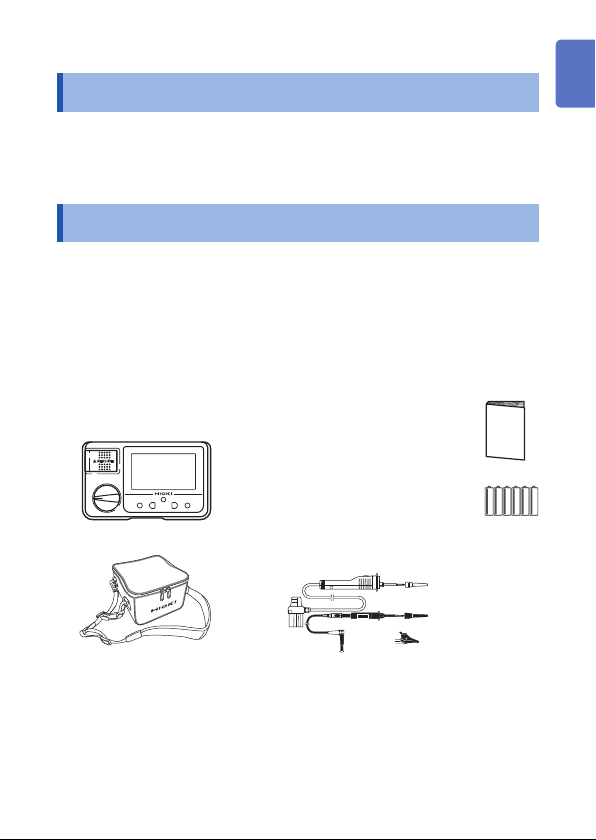
Verifying Package Contents
When you receive the instrument, inspect it carefully to ensure
that no damage occurred during shipping. In particular, check the
accessories, panel switches, and connectors. If damage is evident,
or if it fails to operate according to the specications, contact your
authorized Hioki distributor or reseller.
Conrm that these contents are provided.
□ Model FT4310
Bypass Diode Tester
□ Model C0206 Carrying Case □ Model L9788-11
□ Instruction Manual
□ LR6 Alkaline battery × 6
Test Lead Set with Remote Switch
Model L9788-11 is a set of model
L9788-10 Test Lead with Remote Switch
(Red) and EARTH side lead.
2
3
4
5
6
7
Appx. Index
1
Verifying Package Contents
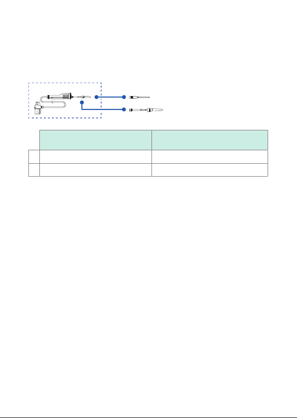
Options
The following options are available for the instrument. Contact your
authorized Hioki distributor or reseller when ordering.
1
2
Product name
Model L9788-92 Breaker Pin CAT III 600 V, 2 A
1
Model L9788-90 Tip Pin CAT III 600 V/CAT II 600 V, 2 A
2
Maximum rated voltage and
maximum rated current
2
Safety Information
Safety Information
This instrument is designed to conform to IEC 61010 Safety
Standards, and has been thoroughly tested for safety prior to
shipment. However, using the instrument in a way not described in
this manual may negate the provided safety features.
Before using the instrument, be certain to carefully read the
following safety notes.
DANGER
Mishandling during use could result in injury or death,
as well as damage to the instrument. Be certain that
you understand the instructions and precautions in
the manual before use.
WARNING
Protective gear
This instrument is measured on a live line. To
prevent an electric shock, use appropriate protective
insulation and adhere to applicable laws and
regulations.
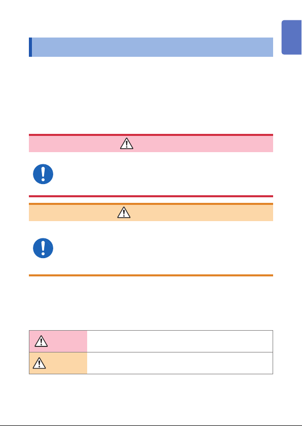
Notation
In this manual, the risk seriousness and the hazard levels are
classied as follows.
DANGER
WARNING
Indicates an imminently hazardous situation that will
result in death or serious injury to the operator.
Indicates a potentially hazardous situation that may result
in death or serious injury to the operator.
1
2
3
4
5
6
7
Appx. Index
3
Safety Information
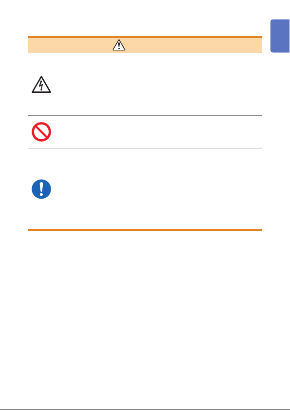
CAUTION
Indicates a potentially hazardous situation that may result
in minor or moderate injury to the operator or damage to
the instrument or malfunction.
Indicates prohibited actions.
Indicates the action which must be performed.
*
(p. )
[ ]
MEASURE
(Bold)
Additional information is presented below.
Indicates the page of reference information.
Screen displays are enclosed in square brackets.
Indicates the names of keys and other controls on the
instrument.
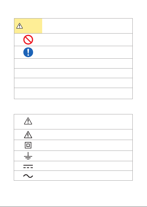
Symbols on the instrument
Indicates cautions and hazards. When the symbol is
printed on the instrument, refer to a corresponding topic
in the Instruction Manual.
Indicates that dangerous voltage may be present at this
terminal.
Indicates a instrument that has been protected throughout
by double insulation or reinforced insulation.
Indicates a grounding terminal.
Indicates DC (Direct Current).
Indicates AC (Alternating Current).
4
Safety Information
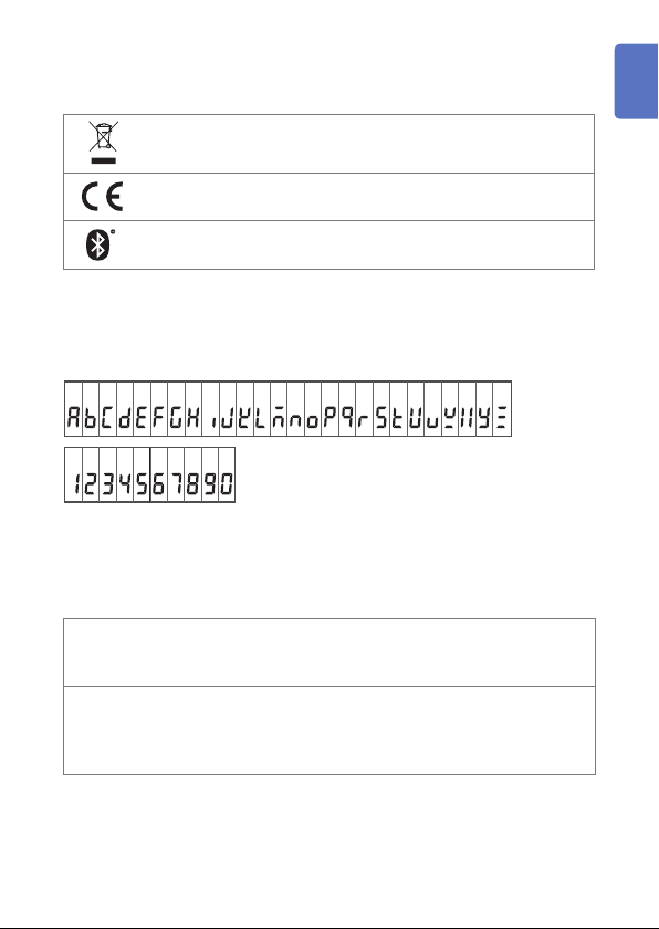
Symbols for various standards
Indicates the Waste Electrical and Electronic Equipment
Directive (WEEE Directive) in EU member states.
Indicates that the product conforms to regulations set out by the
EU Directive.
Indicates that the product incorporates Bluetooth® wireless
technology.
Screen Display
The instrument screen displays the alphanumeric characters as
follows.
A B C D E F G H I J K L M N O P Q R S T U V W X Y Z
1 2 3 4 5 6 7 8 9 0
Accuracy
We dene measurement tolerances in terms of rdg. (reading) and
dgt. (digt) values, with the following meanings:
(reading or displayed value)
rdg.
The value currently being measured and indicated on the
measuring instrument.
(resolution)
The smallest displayable unit on a digital measuring instrument,
dgt.
i.e., the input value that causes the digital display to show a “1” as
the least-signicant digit.
1
2
3
4
5
6
7
Appx. Index
5

Safety Information
Trademarks
• Bluetooth® is a registered trademark of Bluetooth SIG, Inc. (USA).
The trademark is used by HIOKI E.E.CORPORATION under
license.
• Android, Google Play are registered trademarks of Google, Inc.
• IOS is a registered trademark of Cisco in the U.S. and other
countries.
• iPhone, iPad, iPad mini, and iPod Touch are trademarks of Apple
Inc.
• The App Store is a service mark of Apple Inc.
6
Safety Information
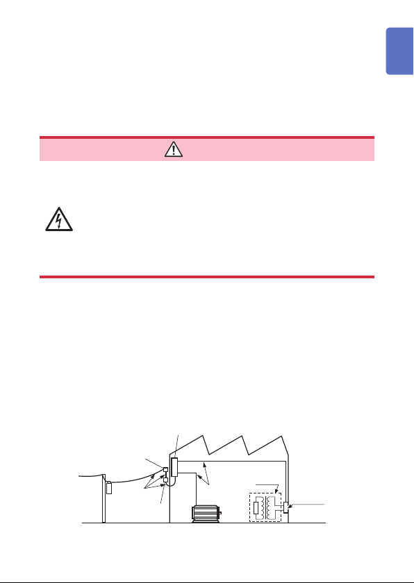
Measurement Categories
To ensure safe operation of measuring instruments, IEC 61010
establishes safety standards for various electrical environments,
categorized as CAT II to CAT IV, and called measurement
categories.
1
DANGER
• Using a measuring instrument in an environment
designated with a higher-numbered category than
that for which the instrument is rated could result in
a severe accident, and must be carefully avoided.
• Never use a measuring instrument that lacks
category labeling in a CAT II to CAT IV measurement
environment. Doing so could result in a serious
accident.
CAT II: When directly measuring the electrical outlet receptacles of
CAT III: When measuring the primary electrical circuits of heavy equipment
CAT IV: When measuring the circuit from the service drop to the service
the primary electrical circuits in equipment connected to an
AC electrical outlet by a power cord (portable tools, household
appliances, etc.)
(xed installations) connected directly to the distribution panel, and
feeders from the distribution panel to outlets.
entrance, and to the power meter and primary overcurrent
protection device (distribution panel).
Distribution panel
Service entrance
Service drop
CAT IV
Power meter
Internal wiring
CAT III
Fixed installation
CAT II
T
Outlet
2
3
4
5
6
7
Appx. Index
7

Operating Precautions
Operating Precautions
Follow these precautions to ensure safe operation and to obtain the
full benets of the various functions.
DANGER
• For your safe operation, do not connect any test
lead to the primary of the distribution panel.
• Do not short-circuit two wires to be measured by
bringing the test leads into contact with them. Arcs
or such grave accidents are likely to occur.
• To prevent a short-circuit or an electric shock, do
not touch the metal part of the connecting test lead
tip.
• To prevent an electric shock, be careful to avoid
shorting live lines with the test leads tip.
If the test lead or the instrument is damaged, there
is a risk of an electric shock. Perform the following
inspection before using them:
• Before using the instrument, check that the coating
of the test leads are neither ripped nor torn and that
no metal parts are exposed. Using the instrument
under such conditions could result in an electric
shock. Replace the test leads with those specied
by our company.
• Verify that it operates normally to ensure that no
damage occurred during storage or shipping. If you
nd any damage, contact your authorized Hioki
distributor or reseller.
8
Operating Precautions
WARNING
• To prevent an electric shock, a short-circuit and
damage to the instrument, observe the following
precautions: Check the position of the rotary
switch before taking measurements. Disconnect
the test leads from the measurement object before
switching the rotary switch.
• Do not use the instrument with circuits that exceed
its ratings or specications. Doing so may damage
the instrument, resulting in an electric shock.
• Use only the specied test leads. Use of any test
lead not specied by our company does not allow
safe measurements.
• To prevent electrical accidents, remove power from
the circuit before connecting the test leads.
• To prevent an electric shock, do not exceed the
lower of the ratings shown on the instrument and
test leads.
1
2
3
4
5
6
7
Appx. Index
9

Operating Precautions
CAUTION
Observe the following to prevent an electric shock, a
short-circuit, or damage to the instrument.
• Turn off any disconnector devices and separate from
the power conditioner before starting the measurements
for the solar battery panel.
• Solar batteries always generate high voltages especially
in day time. Pay attention to prevent an electric shock
for measurements.
• Do not touch any metal parts such as connection box
and disconnector devices directly with bare hands.
Doing so may cause an electric shock due to the
voltage of the generator.
• Maximum rated voltage to terminal of the instrument is
1000 V DC. Do not use the instrument for equipment
with rated voltage over 1000 V DC. Doing so may cause
an electric shock or damage to the instrument.
• The cable is hardened in freezing temperatures. Do not
bend or pull it to avoid tearing its shield or cutting cable.
• The protection rating for the enclosure of this instrument
(based on EN60529) is IP40*.
* IP40:
This indicates the degree of protection provided by the enclosure of
the instrument for use in hazardous locations, entry of solid foreign
objects, and the ingress of water.
4: Protected against access to hazardous parts with wire measuring 1.0 mm
in diameter.
0: The equipment inside the enclosure is not protected against the harmful
effects of water.
10

Installing the instrument
Installing the instrument in inappropriate locations
may cause a malfunction of instrument or may give
rise to an accident. Avoid the following locations.
• Exposed to direct sunlight or high temperature
• Exposed to corrosive or combustible gases
• Exposed to a strong electromagnetic eld or
electrostatic charge
• Near induction heating systems (such as high-
frequency induction heating systems and IH
cooking equipment)
• Susceptible to vibration
• Exposed to water, oil, chemicals, or solvents
• Exposed to high humidity or condensation
• Exposed to high quantities of dust particles
Operating Precautions
WARNING
1
2
3
4
Precautions when transporting the instrument
During shipment of the instrument, handle it carefully so that it is not
damaged due to a vibration or shock.
11
5
6
7
Appx. Index

Operating Precautions
Handling the Instrument
To avoid damage to the instrument, protect it from physical
shock when transporting and handling it. Be especially
careful to avoid physical shock from due to dropping it.
Test leads
• Removable sleeves are attached to the metal pins
at the end of the test leads. To prevent a short-circuit
accident, be sure to use the test leads with the sleeves
attached when performing measurements in the CAT
III measurement category. Remove the sleeves before
starting CAT II circuit measurements. You can use the
test leads with the sleeve removed for secondary side
of the circuit breakers turned off. (Refer to “Measurement
Categories” (p. 7))
• If the sleeves are inadvertently removed during
measurement, stop the measurement.(p. 26)
CAUTION
CAUTION
12

1
Overview
1.1 Product Overview
This is a measuring instrument to test faults of bypass diodes (BPD)
incorporated in solar power generation systems*.
Can be measured even in day time
• Bypass diode condition can be measured without covering the solar panels.
Easy measurements
• Bypass diode condition can be measured with a connection box.
• Measurement results can be sent to a tablet or other mobile device by
Detecting bypass diode deterioration
• The resistance of the bypass route can be measured and deterioration
*: Strings in parallel conguration or special complex conguration cannot be
measured.
®
Bluetooth
of the bypass diode or increase of connector contact resistance between
modules can be detected.
.
1
2
3
4
5
6
7
Appx. Index
13
Names and Functions of Parts
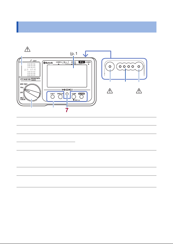
1.2 Names and Functions of Parts
Front
(p. 19, p. 22, p. 38)
1
Display (p. 17)
Top
32
4
(p. 8)
65 7
MEASURE key (p. 15) Measurement switch
1
N(−) terminal Connect the black test lead.
2
Control terminal
3
P(+) terminal
4
Rotary switch (p. 15)
5
Operation keys (p. 16)
6
Live circuit indicator
7
Connect Model L9788-10 Test Lead with
Remote Switch (Red).
Selects the measurement functions (the
measurement modes) and turns off the
power. (p. 15)
Flashes when voltage remains between
measuring terminals.
14
(p. 8)
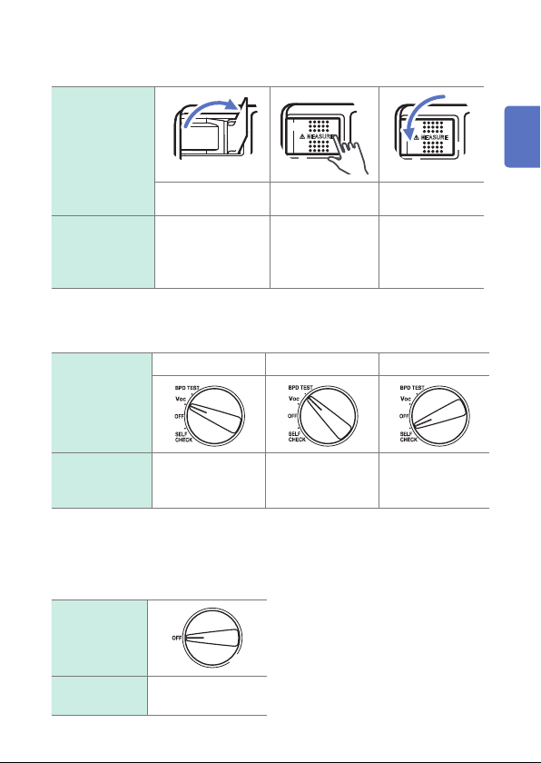
MEASURE key
Names and Functions of Parts
MEASURE key
states
Raise the key
Description in
this manual
Changing measurement mode (turning on the power)
Setting the rotary switch in a position other than OFF turns on the power.
Rotary switch
state
Description in
this manual
Voc mode: Measures open-circuit voltages. (p. 34)
BPD TEST mode: Measures bypass diodes and bypass diode resistors.
Turning off the power
Rotary switch
state
Turn on comparison
display or enable
continuous
measurement.
Voc mode BPD TEST mode Self-check mode
Set the rotary
switch in Voc.
(p. 38)
Press the right of
the key
Press the
MEASURE key.
Set the rotary
switch in BPD
TEST.
Retract the key
Release the
MEASURE key.
Set the rotary
switch in SELF
CHECK.
1
2
3
4
5
6
7
Appx. Index
Description in
this manual
Set off the rotary
switch in OFF.
15
Names and Functions of Parts
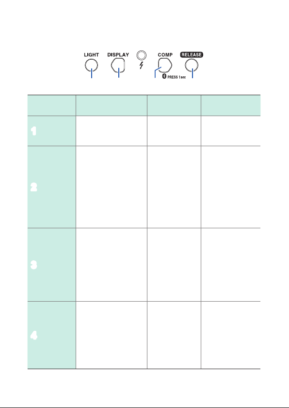
Operation keys
1
Key name Press
Backlight On/Off Turns off the
LIGHT
1
• In BPD TEST mode:
Switches between
the measurement
screen and the
COUNT mode screen
• When comparator
is set: Decrease of
judgment reference
value (p. 32)
• In Voc or BPD TEST
mode: Moves to
comparator setting
screen. (p. 32)
• When comparator
is set: Increase of
judgment reference
value (p. 32)
• In BPD TEST mode/
self-check mode:
Unlock
In locked state,
RELEASE key
ashes. (p. 39)
2
3
Bluetooth
RELEASE
4
DISPLAY
COMP
32
Press and hold
(1 second or more)
auto-backlight
function
• When
comparison
display is set:
Reference
value reset
(p. 35)
• COUNT mode
screen: Count
reset (p. 51)
Bluetooth
communication
On/Off (p. 43)
4
®
–
Turn on the instrument
Cancel the auto
power save
function
Turns on the power
in self- check
mode.
Indicates
the number
of capacitor
discharges.
while holding down
–
–
16
Names and Functions of Parts
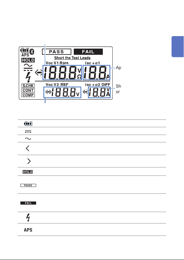
Display
Open-circuit voltage value (Voc mode, (p. 34)) or bypass route resistance
)
(R
BPR
1
Applied current value
Short-circuit current value
or comparison difference
(p. 35)
Open-circuit voltage value (BPD TEST mode) or reference value (REF,
(p. 35))
Battery indicator (four levels) (p. 28)
Appears when measured voltage is DC.
Flashes when measured voltage is AC.
Flashes when the measured value is less than the minimum
display value.
Flashes when the measured value is greater than the maximum
display value.
Appears when the measured value is retained. (p. 36)
Appears when BPD TEST is PASS (good). (p. 40)
Appears when the judgment is PASS (good) with comparator
function. (p. 31)
Appears when BPD TEST is FAIL (defective). (p. 40)
Appears when the judgment is FAIL (defective) with comparator
function. (p. 31)
Flashes during measurement in BPD TEST mode.
The auto power save function will activate 30 seconds after this
mark starts ashing. (p. 29)
2
3
4
5
6
7
Appx. Index
17
Names and Functions of Parts
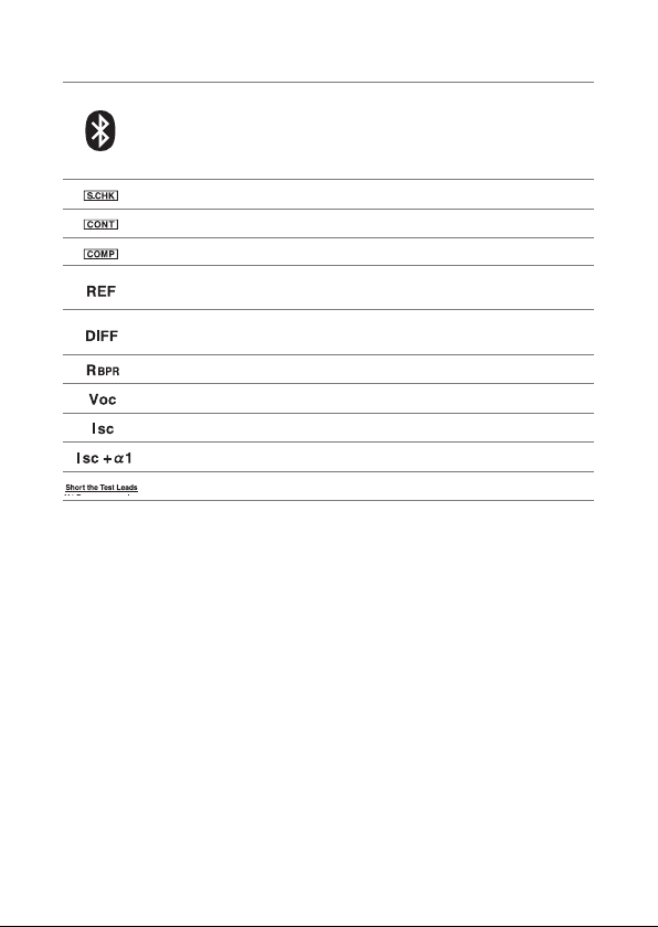
Displays Bluetooth® function state. (p. 43)
• On: Bluetooth
• Off: Bluetooth
• Flashes: Bluetooth
®
function On
®
function Off
®
communication active
Appears while in self-check mode.
Appears while in continuous measurement. (p. 15) (p. 35)
Appears when the comparator function is enabled. (p. 31)
Reference value for comparison display measurement in Voc
mode. (p. 35)
Difference between reference value and measured value for
comparison display measurement in Voc mode. (p. 35)
Bypass route resistance
Open-circuit voltage value (p. 34)
Short-circuit current value
Applied current value
Short the test lead when this mark appears during the self-check.
18
 Loading...