

Page 1

FT3405
FT3406
TACHO HiTESTER
Instruction Manual
Sept. 2016 Revised edition 4
FT3405A981-04 16-09H
EN
Page 2

Page 3

i
Contents
Contents
Introduction ................................................................1
Verifying Package Contents ......................................1
Safety Information .....................................................2
Operating Precautions ...............................................5
Chapter 1 Overview 9
1.1 Product Overview........................................9
1.2 Features......................................................9
1.3 Names and Functions of Part....................10
Chapter 2 Preparing for Measurement 17
Installing or Replacing the Batteries.....17
Connecting the AC Adapter (Option)
(FT3406 only)........................................19
Connecting the Contact Adapter
(Option).................................................20
Connecting the Instrument to a Tripod .20
Connecting the Analog Output Cable
(FT3406 only)........................................21
Connecting the Pulse Output Cable
(FT3406 only)........................................23
Chapter 3 Measurement Procedures 25
Pre-Operation Inspection......................25
3.1 Turning the Power On and Off..................26
3.2 Selecting Measurement Functions............27
3.3 Measurement ............................................28
FT3405A981-04
Page 4

Contents
ii
3.4 Precautions in Measurement of High-Rotation
Objects......................................................29
Chapter 4 Instrument Functionality 31
Measured Value Hold...........................31
Measured Value Overrun Display.........31
Averaging Function.............................. 31
Maximum/Minimum Value Display....... 32
Rotation Detection Display Function.... 32
Configuring the Buzzer......................... 33
Display Backlight..................................33
Auto Power Save (APS) Function........ 33
Resetting the System...........................34
Battery Warning
(Remaining Battery Life Detection)....... 34
Chapter 5 Specifications 35
Function specifications ...................... 35
Accuracy (Not applicable to count
measurement) ................................... 39
General specifications ....................... 40
Chapter 6 Maintenance and Service 41
6.1 Cleaning....................................................41
6.2 Consumables............................................ 41
6.3 Discarding the Instrument.........................41
6.4 Troubleshooting........................................42
Page 5
1
Introduction
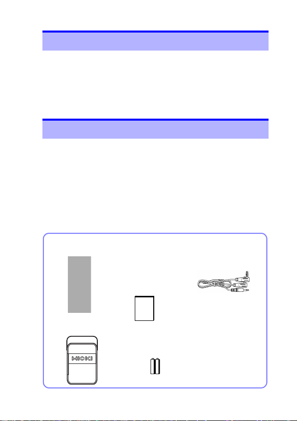
Confirm that these contents are provided.
L9094 Output Cord
(FT3406 only)
FT3405 or FT3406
LR6alkaline battery×2
Instruction manual
(This document)
9211 Reflective Tape
C0202 Carrying
Case
Thank you for purchasing the HIOKI Model FT3405, FT3406
TACHO HiTESTER. To obtain maximum performance from the
instrument, please read this manual first, and keep it handy for
future reference.
The “instrument” in this manual means FT3405 and FT3406.
Refer to " Options" (p.14) for details.
Verifying Package Contents
• When you receive the instrument, inspect it carefully to ensure
that no damage occurred during shipping. In particular, check
the accessories, panel switches, and connectors. If damage is
evident, or if it fails to operate according to the specifications,
contact your dealer or Hioki representative.
•
Use the original packing materials when transporting
the instrument, if possible.
ment, be sure to remove the Contact Adapter, Contact Tip,
Peripheral Ring, Output Cord and AC Adapter before shipping.
1
2
3
4
5
6
To avoid damage to the instru-
7
8
9
10
索引
Page 6
2
Safety Information
This instrument is designed to comply with IEC 61010
Safety Standards, and has been thoroughly tested for safety
prior to shipment. However, mishandling during use could
result in injury or death, as well as damage to the instrument. However, using the instrument in a way not described
in this manual may negate the provided safety features. Be
certain that you understand the instructions and precautions in the manual before use. We disclaim any responsibility for accidents or injuries not resulting directly from
instrument defects.
Safety Symbols
This manual contains information and warnings essential for
safe operation of the instrument and for maintaining it in safe
operating condition. Before using it, be sure to carefully read the
following safety precautions.
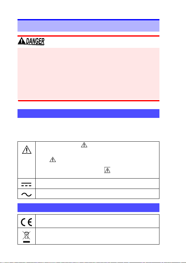
In the manual, the symbol indicates particularly
important information that the user should read before using the instrument.
The symbol printed on the instrument indicates
that the user should refer to a corresponding topic in
the manual (marked with the symbol) before using the relevant function.
Indicates DC (Direct Current).
Indicates AC (Alternating Current).
Symbols for Various Standards
This symbol indicates that the product conforms to
regulations set out by the EC Directive.
Indicates the Waste Electrical and Electronic Equipment Directive (WEEE Directive) in EU member states.
Page 7
3
The following symbols in this manual indicate the relative importance of cautions and warnings.
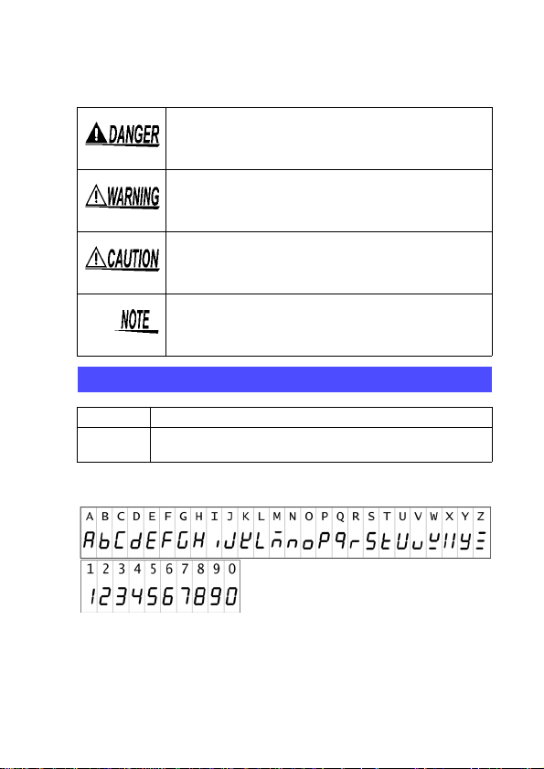
Indicates that incorrect operation presents
an extreme hazard that could result in serious injury or death to the user.
Indicates that incorrect operation presents
a significant hazard that could result in
serious injury or death to the user.
Indicates that incorrect operation presents
a possibility of injury to the user or damage
the instrument.
to
Indicates advisory items related to perfor-
mance or correct operation of the
ment.
Other Symbols
( p. )
The screen of this instrument displays characters in the following manner.
Indicates the location of reference information.
Indicates that descriptive information is pro-
*
vided below.
instru-
1
2
3
4
5
6
7
8
9
10
索引
Page 8

4
Accuracy
We define measurement tolerances in terms of f.s. (ful l scale),
rdg. (reading) and dgt. (digit) values, with the following meanings:
f.s.
(maximum display
value or scale length)
rdg.
(reading or displayed
value)
dgt.
(resolution)
The maximum displayable value or scale
length. This is usually the name of the
currently selected range.
The value currently being measured and
indicated on the measuring instrument.
The smallest displayable unit on a digital
measuring instrument, i.e., the input value that causes the digital display to show
a “1” as the least-significant digit.
Page 9

5
Operating Precautions
Follow these precautions to ensure safe operation and to obtain
the full benefits of the various functions.
Before use
Before using the instrument the first time, verify that it operates
normally to ensure that no damage occurred during storage or
shipping. If you find any damage, contact your dealer or Hioki
representative.
Before using the instrument, make sure that the insulation on
the cable is undamaged and that no bare conductors are
improperly exposed. Using the instrument in such conditions
could cause an electric shock, so contact your dealer or Hioki
representative for repair .
Setting up the instrument
• Although this instrument is dust resistant, it is not completely
dust- or waterproof. To preven t possible damage, avoid using
in dusty or wet environments.
• The protection rating for the enclosure of this device (based on
EN60529) is *IP50.
*
IP50:
This indicates the degree of protection provided by the enclosure of the device against use in hazardous locations, entry of
solid foreign objects, and the ingress of water.
5: Protected against access to hazardous parts with wire mea-
suring 1.0 mm in diameter. Dust-proof type (The penetration
of dust cannot be prevented completely, but quantities of dust
that may hinder the stated operation of equipment or safety
cannot penetrate the enclosure.
0: The equipment inside the enclosure is not protected against
the harmful effects of water.
1
2
3
4
5
6
7
8
9
10
索引
Page 10

6
Instrument Installation
To avoid damage to the instruments and potentially lifethreatening hazards, observe the following precautions.
• Use only the specified/supplied Model Z1004 AC Adapter.
AC adapter input voltage range is 100 to 240 VAC (with
±10% stability) at 50/60 Hz. To avoid electrical hazards
and damage to the instrument, do not apply voltage outside of this range.
• Before turning the instrument on, make sure the supply
voltage matches that indicated on the AC adapter. Connection to an improper supply voltage may damage the
instrument or AC adapter and present an electrical hazard.
• If the protective functions of the instrument are damaged, either
remove it from service or mark it clearly so that others do not
use it inadvertently.
• To avoid damage to the instrument, protect it from physical
shock when transporting and handling. Be especially careful
to avoid physical shock from dropping.
• To avoid breaking the cables, do not bend or pull them.
• For safety reasons, when taking measurements, only use the
L9094 Output Cord provided with the instrument (FT3406
only).
Page 11
7
Storage temperature and humidity:
-10°C to 50°C (14 to 122°F), 80%RH or less (non-condensating)
Accuracy guarantee for temperature and humidity:
23°C±5°C (73°F±9°F), 80%RH or less (non-condensating)
Avoid the following locations that could cause an accident or damage to
the instrument.
Exposed to direct
sunlight
Exposed to high
temperature
Exposed to water,
oil, other chemicals, or solvents
Exposed to high
humidity or condensation
Subject to vibration
In the presence of corrosive or explosive
gases
Exposed to strong
electromagnetic fields
Near electromagnetic
radiators
Near induction heating
systems
(e.g., high-frequency
induction heating systems and IH cooking
utensils)
1
2
3
4
5
6
7
Measurement Precautions
Rotational speed measurement
Always wear protective eyewear as debris from the rotating
object may cause injury.
• Depending on the material of the object to be
measured or method of touching the contact tip,
the measurement error may occur.
• Avoid scratching or dirtying the two lenses inside
the detector window.
8
9
10
索引
Page 12

8
Using the Contact Adapter
• Always use the screw to tighten the contact adapter to
the main body. If it becomes loose, the instrument may
vibrate or be dislocated and become a hazard.
• Be careful when measuring with the contact adapter
because rotation and vibration of the instrument can produce erratic results with either high or low rot ation spee ds.
Hold the main body firmly against the rotator. Do not place
the instrument on a tripod when making measurements.
• When using the contact adapter for measuring, the
instrument is subject to vibration, so measurements
should be made only below 19,999 r/min or 333 r/s.
• When using the Contact Adapter, do not mount the instrument on a tripod.
Handling contact tips
• Verify that the contact tip has been inserted sufficiently
into the adapter axis before beginning measurement. Failure to insert the contact tip sufficiently into the adapter
axis may cause it to separate from the axis, contact the
rotating object, and fly off in the vicinity of the object.
• If the contact tip is able to come into contact with the
rotating object, exercise caution when winding it onto the
object.
• Do not allow rubber contact tips to come into contact with
hot measurement targets. Doing so may cause the contact tip to melt.
Analog Output Terminals and Pulse Output Terminals
To avoid electrical hazards and damage to the instrument,
do not apply voltage exceeding the rated maximum to the
Analog Output Terminals and Pulse Output Terminals.
Page 13

9
Chapter 1 Overview
Overview Chapter 1
1.1 Product Overview
This portable, contactless tachometer uses reflected visiblespectrum light to measure the speed of a rotating object to which
reflective tape has been affixed. It can also be used as a contact-type tachometer by attaching the Z5003 Contact Adapter.
1
2
3
1.2 Features
Contactless measurement for long detection range
The instrument’s ability to detect speed from up to 50 cm distance allows its use in situations where it would be hazardous to approach the
object being measured.
Easy-grip design
Easy-to-grip design and light weight make the instrument easy to han dle.
LCD with a wide field of vie
The FT3405/3406 features a transmissive FSTN liquid crystal d isplay
(LCD), ensuring its readout is easy to read.
Maximum/minimum value hold
Maximum and minimum values are updated continuously so you can
verify variations in rotational speed.
Dust-proof design
The FT3405/3406’s enclosure delivers IP 50-grade protection, allowing it to be used with confidence and peace of mind in environments
characterized by debris (dust, sand, grit, etc.) thrown off by the rotating object.
Drop Proof
The FT3405/3406 can withstand being dropped from a height of 1 m,
making it less likely the unit will be damaged.
Analog Output/ Pulse Output (FT3406 only)
The FT3406 can be used in trend management applications by connecting it to a recorder.
4
5
6
7
8
9
10
索引
Page 14
Chapter 1 Overview
10
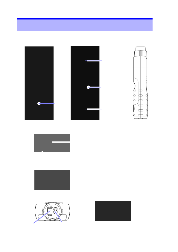
Front
Base
Rear
Side
AC adapter
connector
Analog/pulse
output port
Model FT3405
Battery
Cover
Tripod
screw hole
Grip
Model FT3406
Projection surface
Model FT3406
(shown with cap)
Red light projection/
detection window
Z5003 Contact Adapter
Hole for fixing screw
1.3 Names and Functions of Part
Page 15
11
Chapter 1 Overview
3
1
2
5
6
4
1
2
3
4
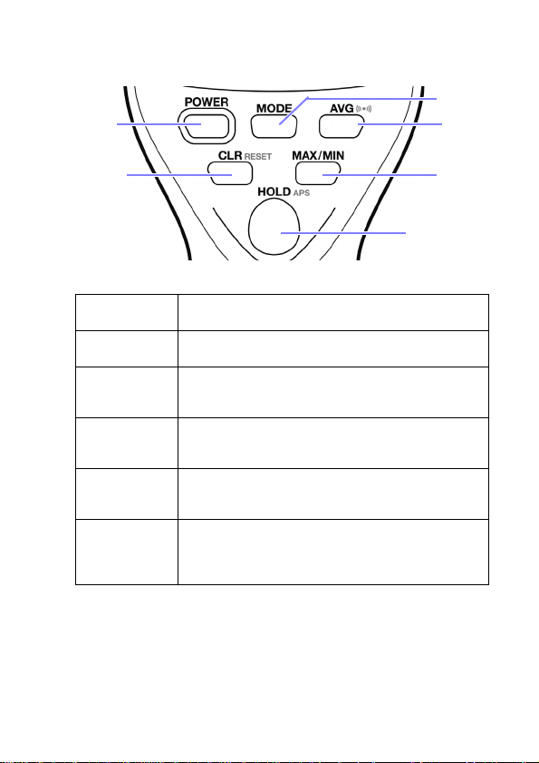
POWER POWER key
1
MODE MODE key
2
AVG AVERAGE key
3
CLR CLEAR key
4
MAX/MIN MAX/MIN key
5
HOLD HOLD key
6
Turns the instrument on and off.
Switches the measurement mode (units).
Switches the sampling time (gate time).
Disabled during count measurement.
Clears the current, maximum, minimum, and
count values.
Displays the maximum and minimum values.
Disabled during count measurement.
Starts and stops updating of measured values.
When reflected light is detected, a buzzer sounds
and an LED lamp built into the key flashes.
5
6
7
8
9
10
索引
Page 16

Chapter 1 Overview
12
[FT3405 display] [FT3406 display]
(FT3406 only)
LCD Display
Display Function Notes
Lights up when the buzzer is
enabled.
Lights up when the Auto Power Save function is enabled.
Displays remaining battery
life.
Turns on when the AC adapter is connected.
Lights up when the hold function is active.
Lights up when the Contact
Adapter is connected.
Lights up during circumferential speed measurement.
Displays the maximum value
obtained since the last time
the instrument was reset.
Displays the minimum value
obtained since the instrument
was last reset.
Lights up when the averaging
function is enabled.
Displays values.
At rotation detection, key
operation
Turns off when the AC
adapter is connected.
Four stages; measurement
is stopped when only the
outline of the battery remains.
Turns off when the AC
adapter is connected.
Turns off when no power is
being supplied from the AC
adapter.
Indicates that the range has
been exceeded.
Flashes when the range is
exceeded.
Page 17

13
Chapter 1 Overview
(FT3406 only)
71
186
38
Unit: mm
Indicates the unit of measurement for rpm measurement,
circumferential speed measurement, and period measurement.
Indicates the unit of measurement for count measurement.
Selects pulse output or analog output. When analog output is selected, you can select
from ×10, ×1, ×0.1, and
×0.01.
Five options:
r/s, r/min, m/s, m/min, ms
Five options:
Pout, Aout×10, Aout×1,
Aout×0.1, Aout×0.01
1
2
3
External Dimensions
4
5
6
7
8
9
10
索引
Page 18

Chapter 1 Overview
14
Options
The following options are available for the FT3405, FT3406
Tacho Hitester. Ask your dealer or Hioki representative when
ordering.
Model, product,
and diagram
Z5003
Contact Adapter
9032
Metal Contact Tip
9033
Rubber Contact Tip
9212
Peripheral Ring
Z1004
AC Adapter
Notes
Dimensions: Approx. 41W×107H×44D mm
(1.61"W×4.21"H×1.73"D)(excluding screw)
Mass: Approx. 46 g (1.6 oz)
*The Z5003 Contact Adapter includes
9032×1, 9033×2, and 9212×1.
Attaches to the Z5003 Contact Adapter.
Attaches to the Z5003 Contact Adapter.
Attaches to the Z5003 Contact Adapter.
Outer circumference: 10 cm
For model FT3406
Rated supply voltage:100 V to 240 V
Output voltage: 5 V
Output current: 1.2 A
Mass: Approx. 69 g (2.4 oz) Plug not included.
Dimensions: Approx. 45W×58H×34D mm
Operating temperature and humidity
: 0°C to 40°C (32 to 104°F), 20 to 80%RH
Storage temperature and humidity
: -20°C to 80°C (-4 to 176°F), 10 to 95%RH
(1.77"W×2.28"H×1.34"D)
Page 19

15
Chapter 1 Overview
UL type VDE type BS type SAA type
Press firmly
Using Z1004 AC Adapter Attachments
The Z1004 AC adapter comes with four plugs. Select and attach
the plug that fits the type of outlet used in your area.
Attaching the plug:
Slide the plug into position as shown in the diagram and insert until you
hear it click into place.
Removing the plug:
Press down firmly on the tab and slide the plug in the direction
indicated by the arrow to remove it.
1
2
3
4
5
6
7
8
9
10
索引
Page 20

Chapter 1 Overview
16
Instruction Manual
Reflective Tape
Peripheral Ring
Contact
Tip x3
Tacho HiTester
Output cord
Contact Adapter
Strap
Inner cover
(Fixable with the hook and
loop fastener)
Accesory pocket
Rubber bands
Divider
Store the instrument as shown below.
Carrying Case inside structure
Page 21

17
Chapter 2 Preparing for Measurement
Preparing for
Measurement
Chapter 2
1
Installing or Replacing the Batteries
Install two alkaline batteries (LR6) before using the instrument.
Verify that sufficient battery life remains before starting measurement. If the instrument indicates low battery life, replace the batteries.
• To avoid electric shock, turn off the power switch and disconnect the AC adapter and output cord before replacing
the batteries.
• Do not mix old and new batteries, or different types of
batteries. Also, be careful to observe battery polarity
during installation. Otherwise, poor performance or
damage from battery leakage could result.
• Battery may explode if mistreated. Do not short-circuit,
recharge, disassemble or dispose of in fire.
• Handle and dispose of batteries in accordance with
local regulations.
• The “ ” indicator flashes when the remaining battery
capacity is low. In this case, the instrument's reliability is not
guaranteed. Replace the battery immediately.
• To avoid corrosion and damage to this instrument from battery
leakage, remove the batteries from the instrument if it is to be
stored for a long time (several months or more).
2
3
4
5
6
7
8
9
10
索引
Page 22

Chapter 2 Preparing for Measurement
18
Turn off the instrument and disconnect the output cord and
1.
AC adapter.
Remove the screws that secure the battery cover in place
2.
on the bottom of the instrument (use a screwdriver).
Remove the battery cover.
3.
If replacing the batteries, remove the old batteries.
4.
Insert two new batteries (LR6), taking care to insert them in
5.
the proper orientation.
Attach the battery cover and tighten the screws.
6.
Page 23

19
Chapter 2 Preparing for Measurement
Connecting the AC Adapter (Option) (FT3406 only)
1
Use only the specified Model Z1004 AC Adapter. AC
adapter input voltage range is 100 to 240 VAC (with
±10% stability) at 50/60 Hz. To avoid electrical hazards
and damage to the instrument, do not apply voltage outside of this range.
• AC adapter output may decrease due to power
supply noise, a momentary loss of power, or
other factors. To keep the instrument operation
from stopping due to these effects when acquiring data for an extended period, it is recommended to use alkaline batteries in the device,
even when operating on AC adapter power.
• Make sure the power is turned off before connecting or disconnecting the AC adapter.
• The AC adapter has priority when connected.
Consequently, power is not drawn from batteries
when the instrument is operating using power
supplied from the AC adapter.
• The indicator is not displayed when no
power is being supplied to the AC adapter or
when there is a power outage (at this time, the
instrument will operate using battery power).
Turn off the instrument.
1.
Remove the cap on the bottom of the grip
2.
and insert the AC adapter jack into the
connector.
Connect the AC adapter plug to the
3.
power supply.
Turn on the instrument.
4.
5.
The indicator will be shown on the
instrument’s display while power is being
supplied.
2
3
4
5
6
7
8
9
10
索引
Page 24

Chapter 2 Preparing for Measurement
20
1
2
*Screw size: 1/4 inch
Connecting the Contact Adapter (Option)
To perform contact measurement, attach the Z5003 Contact
Adapter.
Connect the Contact Adapter as shown
1.
in the diagram to the right.
Tighten the fixing screw on the bottom of
2.
the instrument.
Attach the 9032 Metal Contact Tip, 9033
3.
Rubber Contact Tip, and 9212 Peripheral Ring as needed for your application.
Connecting the Instrument to a Tripod
The instrument can be mounted on a commercially available tripod to perform measurements from an installed (fixed) position.
Mount the instrument on the tripod using the tripod screw hole
on the bottom of the device.
• Do not attempt to rotate the instrument to tighten
the screw when mounting it on a tripod. Instead,
rotate the screw.
• Do not lift or carry the instrument while it is
mounted on a tripod.
Page 25

21
Chapter 2 Preparing for Measurement
(Unit: mV)
Output is calculated from the display value M as follows
Measurement mode
Setting r/min r/s ms counts m/min m/s
Aout×10 M×10/60 M×10
(1,000/M)
×10
r/min
output
M×10/
60×10
M×10
×10
Aout×1M×1/60 M×1
(1,000/M)
×1
M×1/
60×10
M×1
×10
Aout×0.1 M×0.1
M×0.1
×60
(1,000/M)
×0.1×60
M×0.1/
60×10
M×0.1
×
60
×10
Aout×0.01 M×0.01
M×0.01
×60
(1,000/M)
×0.01×60
M×0.01/
60×10
M×0.01
×60×10
Recorder, etc.
L9094 Output Cord
Output port
Connecting the Analog Output Cable (FT3406 only)
Use only the specified L9094 Output Cord. Using a
non-specified cable may result in incorrect measurements due to poor connection or other reasons.
Electrical specifications
1.
Output resistance: 1 kΩ; full scale: 1 V; resolution: 1 mV
Instrument output setting (analog output/pulse output)
2.
Turn off the instrument. Then press the [POWER] key while
pressing and holding the [MODE] key to turn it back on. Hold
[MODE] key for no more than 3 seconds and select the
the
desired "Aout’__" output port setting from Pout, Aout×10,
Aout×1, Aout×0.1, and Aout×0.01.
Refer to the following table for more information.
1
2
3
4
5
6
7
8
After 3 seconds, the setting will take effect, and the instru-
3.
ment will switch to the selected measurement mode.
Connection method
4.
1. Remote the cap from the bottom of the instrument.
2. Connect the L9094 Output Cord to the Output port.
9
10
索引
Page 26

Chapter 2 Preparing for Measurement
22
[For
averaging off
]
[For
averaging on
]
Example output waveform
5.
• At OVER, 1 V is output.
• During hold operation, analog output generates
the current value rather than the hold value.
Page 27

23
Chapter 2 Preparing for Measurement
Frequency counter, etc.
Output port
L9094 Output Cord
Connecting the Pulse Output Cable (FT3406 only)
Function
1.
Outputs pulses detected by the receiver.
Electrical specifications
2.
Output resistance: 1 kΩ
Compatible jack diameter: 3.5 mm
Output level: 0 to 3.3 V
(Active low, low level fixed at 300 μs)
Instrument output setting (analog output/pulse output)
3.
Turn off the instrument. Then press the
pressing and holding the [MODE] key to turn it back on. Hold
the [MODE] key for no more than 3 seconds and select "Pout"
from Pout, Aout×10, Aout×1, Aout×0.1, and Aout×0.01 as
the output port setting.
After 3 seconds, the setting will take effect, and the instru-
4.
ment will switch to the selected measurement mode.
Connection method
5.
1. Remote the cap from the bottom of the instrument.
2. Connect the L9094 Output Cord to the Output port.
[POWER] key while
1
2
3
4
5
6
7
8
9
10
索引
Page 28

Chapter 2 Preparing for Measurement
24
Example output waveform
6.
• Output is generated under all measurement conditions, regardless of the set function or unit.
• To avoid damage to the instrument, do not apply
voltage to output terminals. To avo id damage to
the instrument, do not apply voltage to output terminals
Page 29
25
Chapter 3 Measurement Procedures
Do not use the instrument
if even one point of damage
is found, as it can cause
electric shock.
Replace the damaged items.
Yes
• Is the insulation of the output
cord to be used damaged, or is
bare metal exposed?
• Is damage to the instrument evident?
• Is damage to the AC adapter evident? (FT3406 only
)
<When using batteries>
When the power is
switched on, does the
screen come on?
The batteries may have run
out. Replace the batteries
with new ones and then
check again.
The power cord may be
disconnected or the AC
adapter or instrument internal may be malfunctioning. Request repairs.
<When using AC adapter FT3406 only>
Yes
Yes
No
An error is displayed
When the power is
switched on, does the
screen come on?
No
The instrument may be damaged internally. Request repairs.
Yes
Check the power
supply.
The instrument may be damaged internally.
Request repairs.
Inspection complete
An error is displayed
Inspection complete
Has there been a power outage
or other interruption of power?
No
Measurement
Procedures
• Before using, be sure to read " Safety Information" (p.2), " Operating Precautions" (p.5) and Chapter 2 Preparin g fo r Meas ure ment ( p.17 ).
• Before using the Tester the first time, verify that it operates normally to
ensure that no damage occurred during storage or shipping. If you find
any damage, contact your dealer or Hioki representative.
Pre-Operation Inspection
Instrument inspection
Chapter 3
1
2
3
4
5
Inspection at power on
6
7
8
9
10
索引
Page 30

Chapter 3 Measurement Procedures
26
[All indicators on]
[measurement]
[POWER]
3.1 Turning the Power On and Off
Press and hold the [POWER] key for at least 1 second to turn
1.
on the instrument. All the indicators on the LCD display will
turn on briefly, and the instrument will enter measurement
mode.
To turn off the instrument, press and hold the [POWER] key
2.
for at least 1 second.
Setting and measurement data is treated as follows when
3.
the instrument is turned off:
Measured value (last value) Cleared
Maximum value
Minimum value
Count value Cleared
Measurement unit setting Saved
Averaging setting Saved
Auto Power Save setting Reverts to “ON”
Buzzer setting Saved
Output function setting Saved
• Settings are saved when the instrument is turned
off. Consequently, if power to the instrument is
interrupted without pressing the
after settings have been changed (for example,
by removing the batteries or turning off power to
the AC adapter), those settings will not be saved.
• Settings are saved when the instrument is turned
off by the Auto Power Save function.
Cleared
[POWER] key
Page 31

27
Chapter 3 Measurement Procedures
[MODE]
[MODE]
[MODE]
[MODE]
[MODE]
[MODE]
[MODE]
with Contact Adapter connected
Rotational speed
measurement
Circumferential speed
measurement
Rotational
speed
measurement
Period
measurement
Count
measurement
Circumferential speed
measurement
3.2 Selecting Measurement Functions
The unit of display changes each time the [MODE] key is
pressed.
1
2
3
4
5
6
7
8
9
10
索引
When selecting circumferential speed measurement, attach the 9212 Peripheral Ring to the
Z5003 Contact Adapter.
Page 32

Chapter 3 Measurement Procedures
28
3.3 Measurement
Measurement Method
When performing contactless measurement, reflective
1.
tape is applied to the measurement target. Contact measurement is used to measure rotating objects that cannot
be stopped since it is impossible to apply reflective tape in
such applications. Please note that 19,999 r/min. is the
maximum rotational speed that can be measured.
If the measured value is being held, press the [HOLD] key
2.
to cancel the hold function.
Orient the instrument so that the red light projector is per-
3.
pendicular to the reflective tape.
If performing contact measurement, place the contact tip
or circumferential speed ring in contact with the measurement target.
Hold and read the measured value.
4.
Stopping measured value display updates
Limiting measured value variation
Displaying maximum and minimum values
Stopping the buzzer
Canceling the Auto Power Save function
Resetting the system
Reading the battery life indicator
• When using the Contact Adapter, slippage of the
apparatus may introduce an error component
into readings.
• When using the Contact Adapter, the method
with which the apparatus is brought into contact
with the measurement target may introduce an
error component into readings.
(p.31)
(p.31)
(p.32)
(p.33)
(p.33)
(p.34)
(p.34)
Page 33

29
Chapter 3 Measurement Procedures
*Radius is the distance between the center of the rotating ob-
ject and the center of the tape.
Rotation (r/min.)
Reflective tape
Center
The area of the reflective tape.
60
40
20
60
10
6
5
10 (×10
4
)
1
Radius
Rotating body
Radius
(mm)
3.4 Precautions in Measurement of High-Rotation Objects
Detection of reflected light uses modulated light to minimize the
effects of incident light. When this modulated light is input for a
fixed period of time (about 0.2 ms) or longer, a single pulse is
detected. For this reason, if the light pulse generated by the
passing reflective tape is less than 0.2 ms detection is not possible.
The range that can be detected with a 12 mm square target of
reflective tape is indicated below.
1
2
3
4
5
6
7
8
9
10
索引
Page 34

Chapter 3 Measurement Procedures
30
Attach reflective tape
Area where reflective tape cannot be at-
tached
Rotating body
Rotating body
Reflective portion
Area where light reflects
Non-reflective portion
If the reflective tape cannot be attached within this detection
range, increase the area of the reflective tape so that the generated pulse is 0.2 ms or higher.
For measurement of 30,000 r/min. or higher, use the following
method:
The red light from the instrument should be
adjusted slightly off center as shown, not to the
center of the rotating body.
Page 35

31
Chapter 4 Instrument Functionality
[AVG]
Instrument
Functionality
Measured Value Hold
Stops updating the measured value to allow easy reading.
1. Press
2.
[HOLD] key once to fix the
measured value, preventing
updates. The indicator will
light up.
Press the [HOLD] key again to resume display updates.
Chapter 4
1
2
3
4
5
Measured Value Overrun Display
The indicator will flash when the measurement range is
exceeded.
Averaging Function
The averaging function is used when measured values exhibit
instability. Pressing the
on and off. Activating the averaging function enables the last
digit of the display.
[AVG] key toggles the averaging function
6
7
8
9
10
索引
Page 36

Chapter 4 Instrument Functionality
32
[MAX/MIN]
[MAX/MIN]
[MAX/MIN]
B
u
z
z
e
r
Maximum/Minimum Value Display
1. Pressing the
Current value → Maximum value → Minimum value.
Pressing the [CLR] key while displaying the maximum or
2.
minimum value clears that value to zero.
[MAX/MIN] key toggles the display as follows:
Rotation Detection Display Function
1. When the measurement signal (reflected light signal) is
detected, an LED indicator built into the
[HOLD] key will
flash.
The buzzer will sound when the LED indi-
2.
cator flashes.
See
" Configuring the Buzzer" (p.33)
Page 37

33
Chapter 4 Instrument Functionality
Buzzer disabled
Buzzer enabled
APS enabled
APS disabled
Configuring the Buzzer
The buzzer is configured when turning on the instrument.
Turning off the buzzer:
Turn on the instrument by pressing the
[POWER] key while holding down the [AVG]
key to disable the buzzer.
Re-enabling the buzzer:
Turn on the instrument by pressing the
[POWER] key while holding down the [AVG]
key again to re-enable the buzzer.
Display Backlight
The display backlight remains on at all times and cannot be
turned off.
1
2
3
4
5
Auto Power Save (APS) Function
The Auto Power Save function is configured when turning on the
instrument.
• The function operates automatically when the instrument is
turned on.
• After five minutes of inactivity and no measurement signal
detection, the instrument turns off automatically. This function
is only operative when using battery power.
• "APS" starts to blink at 30 seconds before turning off.
Disabling Auto Power Save: :
Turn on the instrument by pressing the [POWER]
key while holding down the [HOLD] key to disable
Auto Power Save.
Re-enabling Auto Power Save:
Turn off the instrument and then turn it back on.
The APS function will be enabled.
6
7
8
9
10
索引
Page 38

Chapter 4 Instrument Functionality
34
Resetting the System
The system is reset when turning on the system.
Turn on the instrument by pressing the
ing down the
[CLR] key to reset the system.
[POWER] key while hold-
Reset parameters
Measured value Cleared
Maximum and minimum values Cleared
Measurement function Rotational speed measurement
Measurement unit r/min
Auto Power Save function ON
Averaging function OFF
Buzzer ON
Output function Aout×10
Battery Warning (Remaining Battery Life Detection)
The instrument’s remaining battery life is
shown at the top right corner of the display.
Remaining battery
life indicator
• Use of manganese batteries will result in a dra-
• The remaining battery life indicator will not oper-
Battery status
After new alkaline batteries have been loaded
When 2/3 of the battery life remains
When 1/3 of the battery life remains
(Flashing) There is no battery life remaining. When
this indicator is displayed, further measurement is
not possible. Replace the batteries in the instrument.
matically shorter continuous operating time.
ate properly when using nickel-metal-hydride
batteries.
Page 39

35
Chapter 5 Specifications
Specifications Chapter 5
Function specifications
Measurement
functions
Measurement
method
Measurement
mode switching
Averaging
function
Rotational speed measurement:
Rotational speed measurement, period measurement,
count measurement
Circumferential speed measurement:
(when using Z5003 Contact Adapter and 9212 Peripheral Ring)
Visible-spectrum light photoelectric reflection:
Using red visible-spectrum light and reflective tape or a
reflective plate (Z5003 Contact Adapter)
Connection method: Contact or contactless
Contactless measurement detection range:
50 to 500 mm (when instrument is oriented perpendicular
to reflective tape) (when using 12 mm
Reflection detection indicator:
Flashing red LED built into
Sampling period: 62.5 ms to 2 s
Varies with contact/contactless measurement and aver-
aging setting
Display refresh rate: Approx. 0.5 to 10 times/sec
Processing at no input:
Displays 0 (during period meas ur e m e nt , di sp l a ys m a xi-
mum value)
Processing at input overrun: Displays [OVER]
Range switching: Automatic
Setting method: Repeated [MODE] key input
Operation:
Unit of measurement changes with repeated key input
Without Contact Adapter:
Rotational speed (r/min) → Rotational speed (r/s) →
Period (ms) → Count (counts)
With Contact Adapter:
Rotational speed (r/min) → Rotational speed (r/s) →
Period (ms) → Cou nt (counts) → Circumferential speed
(m/min) ( lights up) → Circumferential speed (m/s)
( lights up)
Setting method: Repeated [AVG] key input
Operation: Off → Averaging on with AVG indicator lit
Function description:
Off: Max. gate time of 0.2 s
On: Max. gate time of 2.0 s
Default setting: Off
*Function does not operate (i.e., is turned off) during
count measurement.
2
reflective tape)
[HOLD] key, buzzer
1
2
3
4
5
6
7
8
9
10
索引
Page 40

Chapter 5 Specifications
36
Display value
hold
Display of
maximum/
minimum values
Clearing of
measured values
APS
(Auto Power
Save)
Buzzer Operation description:
Remaining
battery life detection
Contact
Adapter
detection
Power supply
input port
(FT3406 only)
Activation method:
Updating of measured values is stopped with
input. The indicator will light up.
Deactivation method: Repeated
Configuration method: Repeated [MAX/MIN] key input
Operation description:
Normal value → Maximum value ( lights up) →
Minimum value ( lights up)
*This function is not available during count measurement
(the key is disabled).
Operation method:
Operation description:
The current value, maximum value, minimum value,
count measured value, and circumferential sp eed value
are reset to zero.
Notes:
The measured value is also cleared when switching mea surement modes and changing the averaging sett ing.
Operation description:
The instrument turns off after 5 minutes of inactivity and
no measurement signal detection.
Initial state: On ( lights up)
Deactivation method: Power-on option
*APS is automatically disabled when the AC adapter is
connected (when a standard voltage is detected).
The buzzer sounds for 30 ms each time a rotation is de-
tected.
Initial state: On ( lights up)
Deactivation method: Power-on option
*The buzzer also sounds when keys are pressed (this
functionality cannot be disabled).
Operation description:
At 1.9 V (±0.1 V), the remaining battery life is shown as
0, the battery outline flashes, and the measured value
display is turned off. At and below 1.8 V (±0.1 V) , t he i n-
strument turns off.
Function description:
Attachment of the Contact Adapter is automatically detected.
Operation description:
When switching measurement modes, the circumferen-
tial measurement setting is available.
Application: Z1004 AC adapter connection
Output port: 5.5 mm diameter, center positive
Max. input voltage: DC ±5 V ±0.3 V
[CLR] key input
[HOLD] key
[HOLD] key input
[HOLD] + [POWER]
[AVG] + [POWER]
Page 41

37
Chapter 5 Specifications
Measurement mode
Setting r/min r/s ms
counts
m/min m/s
Aout×10 M×10/60 M×10 (1,000/M)
×10
r/min
output
M×10/
60×10
M×10
×10
Aout×1M×1/60 M×1 (1,000/M)
×1
M×1/
60×10
M×1
×10
Aout×0.1 M×0.1 M×0.1
×60
(1,000/M)
×0.1×60
M×0.1/
60×10
M×0.1
×
60
×10
Aout×0.01 M×0.01 M×0.01
×60
(1,000/M)
×0.01×60
M×0.01/
60×10
M×0.01×60
×10
AC adapter
detection
(FT3406 only)
Pulse output
(FT3406 only)
Analog output
(FT3406 only)
Output information: Output is calculated from the display value M as follows
Operation description:
The indicator lights up when voltage is detected.
Notes:
The indicator turns off when the detected voltage
value is 0 (for example, during a power outage), even if
the adapter is connected.
Port profile: 3.5 mm diameter, earphone jack type
(Shared port; switchable between pulse output and ana-
log output)
Output resistance: 1 kΩ
Output level: 0 to 3.3 V
Output information: Outputs the detectio n pulse.
Active-low output
Low output duration: 300 μs
Output port: 3.5 mm diameter, earphone jack type
(shared port; switchable between pulse output and analog output)
Output resistance: 1 kΩ
Output level: 0 to 1 V f.s.
Resolution: 1 mV
Response speed: Varies with averaging setting
Accuracy: ±2% f.s
Accuracy guarantee temperature and humidity range:
23°C ±5°C, 80% RH or less
Outside above temperature range: Add accuracy
specifications × 0.1 × (|T-23| ), where T is the operating
temperature in Celsius.
.
1
2
3
4
5
6
7
8
9
10
Output port
setting
(FT3406 only)
Configuration method: Power-on option [MODE] + [POW-
, then [MODE] key input to cycle Aout×10 → Aout×1 →
ER]
Aout×0.1 → Aout×0.01 → Pout
Setting takes effect after 3 seconds of inactivity.
Initial setting: Aout×10
(Unit:mV)
索引
Page 42

38
Instrument
Assigned
function
Regular function Power-on option
[POWER] Power switch ---[MODE] Measurement mode
switching
Output port setting
(FT3406 only)
[AVG] Averaging function
setting
Buzzer setting
[MAX/MIN] Maximum and mini-
mum value display
----
[CLR] Value clear System reset
[HOLD] Hold/cancel
measured value
APS setting
operation
Chapter 5 Specifications
Display Transmissive LCD: FSTN
Ranges and measurement ranges
Note 1: The lowermost digit is fixed at 0 at speeds of 20,000 r/min and over.
Note 2: The lowermost digit is fixed at 0 when the averaging setting is off.
Backlight: Always on
(1) Rotational speed measurement
MODE Range
Rotational
speed
measure-
ment
(r/min)
Rotational
speed
measure-
ment
(r/s)
Contactless measurement Contact measurement
AVG=ON AVG=OFF AVG=ON AVG=OFF
30.00 to
1
199.99
200.0 to
2
1999.9
2000 to
3
19999
20000 to
4
99990
0.5000 to
1
1.9999
2.000 to
2
19.999
20.00 to
3
199.99
200.0 to
4
1600.0
--
300.0 to
1999.0
2000 to
19990
20000 to
99990
--
5.000 to
19.990
20.00 to
199.90
200.0 to
1600.0
15.00 to
199.99
200.0 to
1999.9
2000 to
19999
-- --
0.2500 to
1.9999
2.000 to
19.999
20.00 to
199.99
200.0 to
333.0
--
150.0 to
1999.0
2000 to
19990
--
2.500 to
19.990
20.00 to
199.90
200.0 to
333.0
Page 43

39
Period
AVG=ON AVG=OFF
Up to 9,999 counts ±1dgt. ±10dgt.
10,000 counts or more ±2dgt. ±20dgt.
20,000 counts or more
(r/min mode only)
±20dgt. ±100dgt.
Period measurement only
±0.5%rdg. is added to
above-mentioned accuracy.
measure-
ment
(ms)
Count
measure-
ment
(count)
Chapter 5 Specifications
0.6000 to
1
1.9999
2.000 to
2
19.999
20.00 to
3
199.99
200.0 to
4
1999.9
1
0.6000 to
1.9990
2.000 to
19.990
20.00 to
199.90
--
(Input conditions: Up to rotational speed
0 to 999999
measurement upper limit)
-- --
3.000 to
19.999
20.00 to
199.99
200.0 to
3999.9
3.000 to
19.990
20.00 to
199.90
200.0 to
399.0
1
2
3
(2) Circumferential speed measurement
MODE Range
Circumferential speed
measurement
(m/min)
Circumferential speed
measurement
(m/s)
1 1.500 to 19.999 -2 20.00 to 199.99 15.00 to 199.90
3 200.0 to 1999.9 200.0 to 1999.0
1 0.0250 to 1.9999 0.2500 to 1.9990
2 2.000 to 19.999 2.000 to 19.990
3 20.00 to 33.30 20.00 to 33.30
AVG=ON AVG=OFF
Accuracy (Not applicable to count measurement)
Contact measurement
4
5
6
7
8
9
10
索引
Page 44

Chapter 5 Specifications
40
General specifications
Guaranteed
accuracy period
Operating
temperature
Operating
humidity
Storage
temperature and
humidity
Operating
environment
Drop proof 1 m onto concrete surface
Power supply 5 VDC or LR6 alkaline battery × 2
Rated supply
voltage
Maximum rated
power
Continuous op-
erating time
Dimensions
(max.)
Mass Approx. 230g (8.1 oz) (Including battery)
Dust resistance IP50 (EN60529)
Applicable
Standards
Accessory Instruction manual ...............................................................1
Option Z5003 Contact Adapter
1 year
0 to 50°C (32 to 122°F)
Up to 40°C (104°F) 80%RH or less
40°C to 45°C (104 to 113°F) 60%RH or less
45°C to 50°C (113 to 122°F) 50%RH or less (non-condensing)
-10°C to 50°C (14 to 122,°F)
80%RH or less (non-condensing)
Indoors, Pollution degree 2, altitude up to 2000 m (6562-ft.)
Battery power 1.5 V DC × 2
AC adapter 5 V DC ±0.3 V
0.5 VA
FT3405: Approx. 30 hours
FT3406: Approx. 25 hours
*When using alkaline batteries with buzzer off.
Approx. 71(W)×186(H) × 38(D)mm
(2.80"W × 7.32"H ×1.50"D)
EMC :EN61326
Safety :EN61010
9211 Reflective Tape...........................................................1
L9094 Output Cord (FT3406 only).......................................1
C0202 Carrying Case..........................................................1
LR6 alkaline battery.............................................................2
9032 Metal Contact Tip
9033 Rubber Contact Tip
9212 Peripheral Ring
Z1004 AC Adapter (FT3406 only)
L9094 Output Cord (FT3406 only)
9211 Reflective Tape
C0202 Carrying Case
Page 45

41
Chapter 6 Maintenance and Service
Maintenance and
Service
Chapter 6
1
6.1 Cleaning
• To clean the instrument, wipe it gently with a soft cloth moistened with water or mild detergent. Never use solvents such as
benzene, alcohol, acetone, ether, ketones, thinners or gasoline, as they can deform and discolor the case.
• Wipe the Lens and LCD gently with a soft, dry cloth.
6.2 Consumables
Replaceable Parts and Operating Lifetimes.
Useful life depends on the operating environment and frequency
of use. Operation cannot be guaranteed beyond the following
periods For replacement parts, contact your dealer or Hioki rep-
resentative.
Part Operating lifetime
Measurement visible-spectrum red
LED and sensor
LCD backlight 50,000 hours
Batteries Operating lifetime varies with conditions of use.
8,000 hours (about 3 years at 8 hours of use per day)
A reduction in detection range indicates the operating
lifetime is almost over. The instrument should be repaired.
If the display becomes difficult to see (dim), the instrument should be repaired.
When the remaining battery life indicator is displayed
as , replace the batteries with new batteries.
6.3 Discarding the Instrument
• Battery may explode if mistreated. Do not short-circuit,
recharge, disassemble or dispose of in fire.
• Handle and dispose of batteries in accordance with local regulations.
2
3
4
5
6
7
8
9
10
索引
Page 46

Chapter 6 Maintenance and Service
42
6.4 Troubleshooting
If damage is suspected, check the “Before returning for repair”
before contacting your dealer or Hioki representative.
Before returning for repair:
Symptom Checks and Remedy
Although you have
turned on the power switch, the
screen display
does not appear.
The instrument
turns off.
is lit up. The RING setting cannot be activated without f irst at-
The detection
range for contactless measurement
is low.
Have the batteries been inserted in the proper orientation?
(p.17)
Are the batteries correctly inserted?
Insert the new batteries.
Has the AC adapter been connected properly?
(FT3406 only)
(p.19)
Is the battery dead?
→ Replace the battery.
Is the auto power save function being activated?
→ Check the auto power save setting.
(p.33)
AC adapter output may decrease due to power supply noise, a momentary loss of power, or other factors, causing the instrument to switch to battery
power. If no batteries are loaded in the i nstrument, it
will turn off.
Keep fresh batteries in the instrument.
taching the Contact Adapter.
The sensor’s characteristics vary with temperature.
As the ambient temperature increases, the detection
range will shorten. This does not indicate an instrument malfunction.
This message indicates an internal instrument malfunction. The instrument should be repaired.
(p.17)
(p.17)
Pack the instrument so that it will not sustain damage during
shipping, and include a description of existing damage. We do
not take any responsibility for damage incurred during shipping.
Page 47

Page 48

Page 49

Page 50

 Loading...