

Hioki DT4281, DT4282 Instruction Manual

DT4281
DT4282
DIGITAL MULTIMETER
Instruction Manual
Apr. 2015 Revised edition 6
DT4281A981-06 15-04H
EN

Contents
Introduction .........................................................................1
Verifying Package Contents ..............................................1
Options (sold separately) ..................................................2
Safety Notes ........................................................................ 5
Usage Notes ...................................................................... 10
1 Overview 15
1.1 Overview and Features .................................15
1.2 Parts Names and Functions .........................16
1.3 Display ...........................................................21
1.4 Alarm Display and Battery Indicator ...........23
1
1
1
2
2
3
2 Preparation for Measurements 25
2.1 Measurement Workfl ow ................................ 25
2.2 Inserting/Replacing Batteries ...................... 26
2.3 Using Test Leads ...........................................28
2.4 Installation in Measurement Location .........31
Using the instrument with the stand .......................... 31
Hanging the instrument with the strap ......................31
3 Performing Measurements 33
3.1 Inspection Before Use ..................................33
3.2 Measuring Voltage.........................................38
Measuring AC voltage ............................................... 38
Measuring DC voltage ..............................................39
Measuring synthesized voltage of DC and AC .........39
Measuring voltage of DC and AC components ......... 40
3.3 Measuring Frequencies ................................40
3.4 Decibel Conversion (dBm/dBV) ................... 41
DT4281A981-06
4
5
6
7
Ind.Appx.
i

Contents
3.5 Checking Continuity ..................................... 42
3.6 Measuring Diode ........................................... 43
3.7 Measuring Resistance .................................. 44
3.8 Measuring Temperatures ..............................45
3.9 Measuring Electrostatic Capacities ............. 47
3.10 Measuring Conductances
(DT4282) ................48
3.11 Measuring Current ........................................49
Measuring DC/AC .....................................................49
3.12 Measuring AC Using Clamp-on Probe
(DT4281) ......................................................... 51
3.13 4-20 mA (0-20 mA) % Conversion ................53
4 Using Instrument Conveniently 55
4.1 Selecting the Measurement Range .............. 55
Measuring with the auto range .................................55
Measuring with the manual range ............................. 55
4.2 Retaining the Measured Value ..................... 57
Retaining the measured value manually (HOLD) .....57
Automatically retaining the measured value
when the value stabilizes (AUTO HOLD)..................57
4.3 When the Measured Value Fluctuates
(SLOW) ........................................................... 59
4.4 Removing the Harmonic Components
of the Inverter (FILTER) ................................. 60
4.5 Checking the Maximum/Minimum Value
(MAX/MIN) ......................................................61
4.6 Checking the Peak Value (V • A PEAK) .......62
4.7 Checking the Relative Value/Performing
Zero Adjustment ............................................63
Checking the relative value (REL) ............................63
Performing zero adjustment ...................................... 64
ii

Contents
4.8 Using the Memory Function .........................65
Saving the measured value (MEM) ..........................65
Reading the memory data (READ) ........................... 67
Clearing the memory data (CLEAR) ......................... 68
Clearing all memory data ..........................................68
4.9 Muting the Buzzer .........................................69
4.10 Turning On the Backlight .............................. 69
4.11 Using the Auto Power Save (APS) ............... 70
4.12 Using Plus/Minus Judgment Function
for Measurement Value ................................. 71
4.13 Communicating with PC ...............................72
4.14 Setting and Checking the System ...............74
Checking that all indicators are displayed ................74
Checking the software version of the instrument ......74
Changing the temperature display unit ..................... 75
4.15 Resetting the System .................................... 76
Table of default settings ............................................76
4.16 Power-on Option Table .................................77
5 Specifi cations 79
5.1 Electrical Characteristics ............................. 79
5.2 Accuracy Table .............................................. 81
5.3 General Specifi cations .................................95
1
212
3
4
5
6
6 Maintenance and Service 99
6.1 Repair Inspection and Cleaning ................. 99
6.2 Troubleshooting ..........................................101
6.3 Error Display ................................................ 105
6.4 Replacing Fuses .......................................... 106
iii
7
Ind.Appx.

Contents
Appendix Appx.1
Appx. 1 RMS and Average .............................Appx.1
Appx. 2 Operation Example ........................... Appx.2
Appx. 3 Capacitor Capacity Measurement
Principle.............................................Appx.3
Appx. 4 Dedicated Software
(DMM Communicator) ......................Appx.4
iv
Introduction
Introduction
Thank you for purchasing the HIOKI DT4281, DT4282 Digital
Multimeter. To obtain maximum performance from the product,
please read this manual fi rst, and keep it handy for future reference.
1
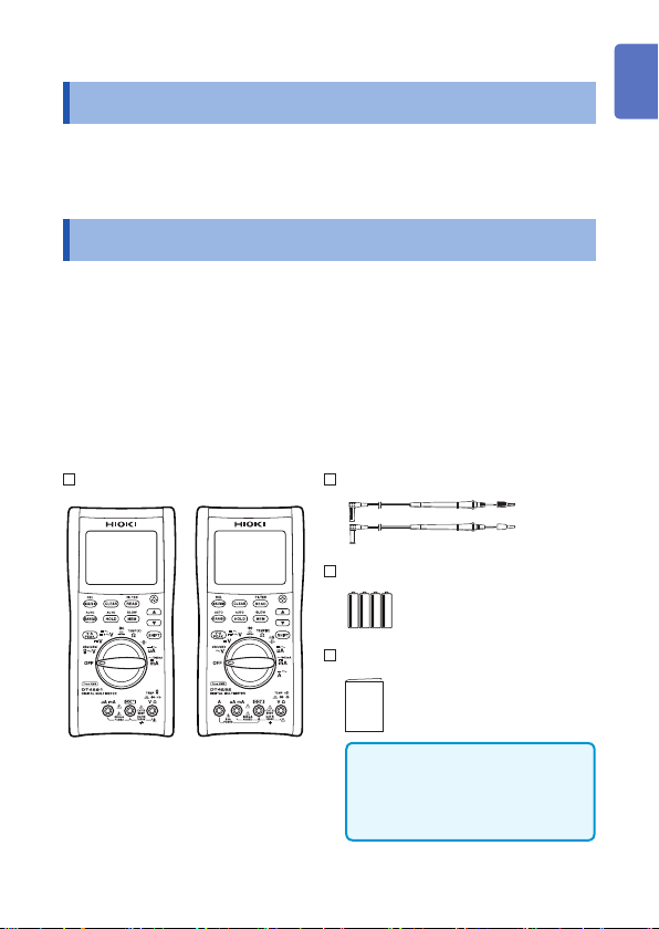
Verifying Package Contents
When you receive the instrument, inspect it carefully to ensure that
no damage occurred during shipping.
In particular, check the accessories, panel switches, and
connectors. If damage is evident, or if it fails to operate according
to the specifi cations, contact your authorized Hioki distributor or
reseller.
Check the package contents as follows.
DT4281 or DT4282
DT4281 DT4282
L9207-10 Test Lead (p. 28)
LR6 Alkaline battery × 4
Instruction Manual
(English)
Instruction manuals may also
be available in other languages.
Please visit our website at
http://www.hioki.com
/
2
3
4
5
6
7
Ind.Appx.
1
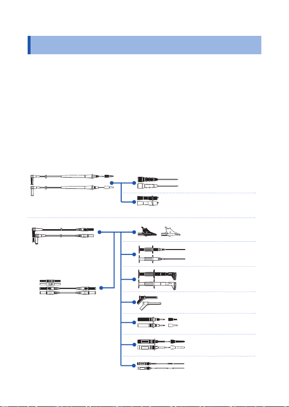
Options (sold separately)
Options (sold separately)
The following options are available for the instrument. Contact your
authorized Hioki distributor or reseller when ordering.
Connecting cables
*1: CATIV 600 V/CATIII 1000 V/CATII 1000 V
*2: CATIV 600 V/CATIII 1000 V
*3: CATIII 1000 V *5: CATIII 300 V/CATII 600 V
*4: CATIII 600 V *6: 33 V AC/70 V DC
*7: CATIII 600 V/CATII 600 V
6
L4933*
Contact Pin Set
L9207-10*
1
Test Lead
2
L4930*
Connection Cable Set
(Length: 1.2 m)
2
L4931*
Extension Cable Set
(Length: 1.5 m, with the
coupling connector)
5
L4934*
Small Alligator Clip Set
2
L4935*
Alligator Clip Set
3
9243*
Grabber Clip
4
L4936*
Bus Bar Clip Set
3
L4937*
Magnetic Adapter Set
1
L4932*
Test Pin Set
7
L4938*
Test Pin Set
4
L4939*
Breaker Pin Set
2
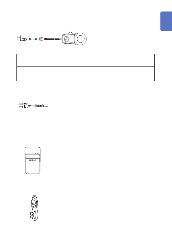
Options (sold separately)
For the clamp current measurement (only compatible with the DT4281)
9010-50, 9018-50, 9132-50*
Clamp-on Probe
9704 Conversion Adapter
4
1
Clamp-on probe
9010-50, 9018-50 500 A rms46 mm or less
9132-50 1000 A rms55 mm or less, 80 × 20 mm bus-bar
Temperature measurement
C0202 Carrying Case
Z5004 Magnetic Strap (p. 31)
Rated
current
DT4910 Thermocouples (K) (p. 45)
• Temperature measuring junction: Exposed type (welding)
• Sensor length: Approx. 800 mm
• Operating temperature: -40°C to 260°C (temperature
measuring part), -15°C to 55°C (connector)
The instrument, test leads, instruction manual, and others
can be stored in the case.
Attach this strap to the instrument and secure it on the
wall surface such as a metal plate for use.
Diameter of the measurable
conductor
2
3
4
5
6
7
Ind.Appx.
3

Options (sold separately)
DT4900-01 Communication Package (USB) (p. 72)
A communication adapter, USB cable, PC software,
and communication specifi cations are included.
The instrument data can be stored on the PC.
4
Safety Notes
Safety Notes
This instrument is designed to conform to IEC 61010 Safety
Standards, and has been thoroughly tested for safety prior to
shipment. However, using the instrument in a way not described in
this manual may negate the provided safety features.
1
Before using the instrument, be certain to carefully read the
following safety notes.
DANGER
Mishandling during use could result in injury or death,
as well as damage to the instrument. Be certain that
you understand the instructions and precautions in
the manual before use.
WARNING
With regard to the electricity supply, there are risks
of electric shock, heat generation, fi re, and arc
discharge due to short circuits. If persons unfamiliar
with electricity measuring instruments are to use
the instrument, another person familiar with such
instruments must supervise operations.
Protective gear
WARNING
To avoid electric shock when measuring live lines,
wear appropriate protective gear, such as insulated
rubber gloves, boots and a safety helmet.
2
3
4
5
6
7
Ind.Appx.
5
Safety Notes
Notation
In this manual, the risk seriousness and the hazard levels are
classifi ed as follows.
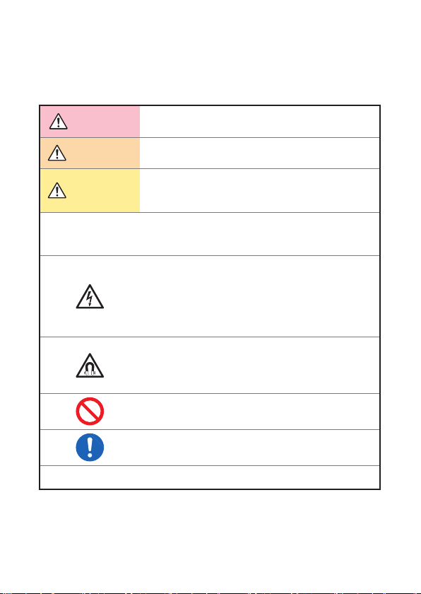
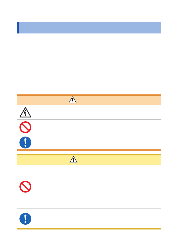
DANGER
WARNING
CAUTION
IMPORTANT
Indicates an imminently hazardous situation that will
result in death or serious injury to the operator.
Indicates a potentially hazardous situation that may
result in death or serious injury to the operator.
Indicates a potentially hazardous situation that may
result in minor or moderate injury to the operator or
damage to the instrument or malfunction.
Indicates information related to the operation of the
instrument or maintenance tasks with which the
operators must be fully familiar.
Indicates a high voltage hazard.
If a particular safety check is not performed or the
instrument is mishandled, this may give rise to a
hazardous situation; the operator may receive an
electric shock, may get burnt or may even be fatally
injured.
Indicates a strong magnetic-fi eld hazard.
The effects of the magnetic force can cause
abnormal operation of heart pacemakers and/or
medical electronics.
Indicates prohibited actions.
Indicates the action which must be performed.
*
Additional information is presented below.
6
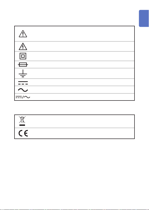
Symbols affi xed to the instrument
Indicates cautions and hazards. When the symbol is printed on
the instrument, refer to a corresponding topic in the Instruction
Manual.
Indicates that dangerous voltage may be present at this terminal.
Safety Notes
1
Indicates a double-insulated device.
Indicates a fuse.
Indicates a grounding terminal.
Indicates DC (Direct Current).
Indicates AC (Alternating Current).
Indicates DC (Direct Current) or AC (Alternating Current).
Symbols for various standards
Indicates the Waste Electrical and Electronic Equipment
Directive (WEEE Directive) in EU member states.
Indicates that the instrument conforms to regulations set out by
the EC Directive.
2
3
4
5
6
7
Ind.Appx.
7
Safety Notes
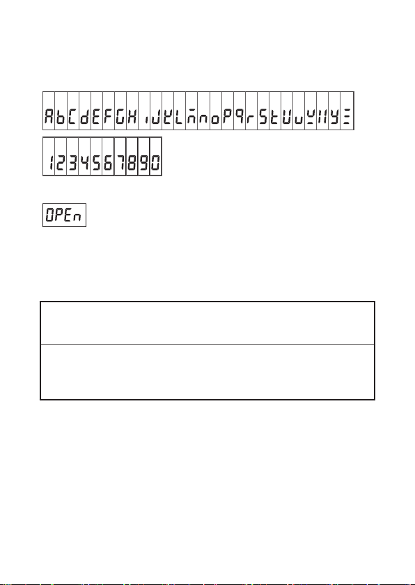
Screen display
This instrument uses the following screen displays.
AB CD E FGH I J K LMNOPQR S TU VWXY Z
123456 7890
A different display is used in the case below.
Appears when a broken Thermocouple (K) is detec ted. (p. 45)
Accuracy
We defi ne measurement tolerances in terms of rdg. (reading) and
dgt. (digit) values, with the following meanings:
(Reading or displayed value)
rdg.
The value currently being measured and indicated on the
measuring instrument.
(Resolution)
The smallest displayable unit on a digital measuring instrument,
dgt.
i.e., the input value that causes the digital display to show a “1”
as the least-signifi cant digit.
8
Safety Notes
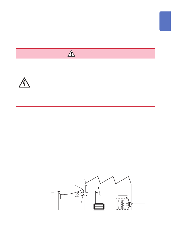
Measurement categories
To ensure safe operation of measuring instruments, IEC 61010
establishes safety standards for various electrical environments,
categorized as CAT II to CAT IV, and called measurement categories.
DANGER
• Using a measuring instrument in an environment
designated with a higher-numbered category than
that for which the instrument is rated could result in
a severe accident, and must be carefully avoided.
• Using a measuring instrument without categories in
an environment designated with the CAT II to CAT
IV category could result in a severe accident, and
must be carefully avoided.
This instrument conforms to the safety requirements for CAT III 1000 V, CAT
IV 600 V measuring instruments.
CAT II: When directly measuring the electrical outlet receptacles of
CAT III: When measuring the primary electrical circuits of heavy equipment
CAT IV: When measuring the circuit from the service drop to the service
See: “2.3 Using Test Leads” (p. 28)
the primary electrical circuits in equipment connected to an
AC electrical outlet by a power cord (portable tools, household
appliances, etc.)
(fi xed installations) connected directly to the distribution panel,
and feeders from the distribution panel to outlets
entrance, and to the power meter and primary overcurrent
protection device (distribution panel)
Distribution panel
Service entrance
Service drop
CAT IV
Power meter
Internal wiring
CAT III
Fixed installation
CAT II
T
Outlet
1
2
3
4
5
6
7
Ind.Appx.
9
Usage Notes
Usage Notes
Follow these precautions to ensure safe operation and to obtain the
full benefi ts of the various functions.
DANGER
If the test lead or the instrument is damaged, there is
a risk of electric shock. Before using the instrument,
perform the following inspection.
• Before using the instrument, check that the coating of
the test leads are neither ripped nor torn and that no
metal parts are exposed. Using the instrument under
such conditions could result in electrocution. Replace
the test leads with those specifi ed by our company.
• Before using the instrument for the fi rst time, verify
that it operates normally to ensure that no damage
occurred during storage or shipping. If you fi nd any
damage, contact your authorized Hioki distributor or
reseller.
Installation
Installing the instrument in inappropriate locations may cause a
malfunction of instrument or may give rise to an accident. Avoid the
following locations. For details on the operating temperature and
humidity, see the specifi cations. (p. 95)
CAUTION
• Exposed to direct sunlight or high temperature
• Exposed to corrosive or combustible gases
• Exposed to water, oil, chemicals, or solvents
• Exposed to high humidity or condensation
• Exposed to a strong electromagnetic fi eld or electrostatic
charge
• Exposed to high quantities of dust particles
• Near induction heating systems (such as high-frequency
induction heating systems and IH cooking equipment)
• Susceptible to vibration
10
Usage Notes
Handling the cables
WARNING
To prevent electric shock, when measuring the
voltage of a power line use a test lead that satisfi es
the following criteria:
• Conforms to safety standards IEC61010 or EN61010
• Of measurement category III or IV
• Its rated voltage is higher than the voltage to be
measured
All of the optional test leads for this device conform
to the safety standard EN61010. Use a test lead in
accordance with its defi ned measurement category
and rated voltage.
CAUTION
• Avoid stepping on or pinching the cable, which could
damage the cable insulation.
• To avoid damaging the cables, do not bend or pull the
leads and the probe bases.
The ends of the test leads are sharp. Be careful to avoid
injury.
For the test leads supplied with the instrument or the options to be connected
to the instrument, see the following information.
Accessories and options Reference
Test lead “2.3 Using Test Leads” (p. 28)
Thermocouples (K) “3.8 Measuring Temperatures” (p. 45)
Clamp-on probe
USB cable “4.13 Communicating with PC” (p. 72)
Magnetic strap
See the Instruction Manual which
accompanies the optional clamp.
“2.4 Installation in Measurement
Location” (p. 31)
1
2
3
4
5
6
7
Ind.Appx.
11
Usage Notes
Precautions during measurement
WARNING
If the instrument is used in locations where the rating
indicated on the instrument or probes is exceeded,
the instrument may be damaged resulting in personal
injury. Do not use the instrument in such locations.
See “Measurement categories” (p. 9).
• With regard to the 10 A range, the maximum input
current is 10 A DC/10 Arms AC. Supplying a current
in excess of the maximum input may damage the
instrument and result in personal injury. Do not
supply current in excess of the specifi ed limit. (Only
the DT4282)
Observe the following to avoid electric shock and/or
short circuits.
• Hazardous voltage may be generated in a free
measurement terminal. Do not touch the free
terminal.
• Use only test leads and optional equipment
specifi ed by our company.
• Do not allow the metal part of the test lead to touch
any exposed metal, or to short between 2 lines.
Never touch the metal end.
• When connecting the clip-type test lead to the
active terminal, do not allow the lead to touch any
exposed metal, or to short between 2 lines.
• When the clamp-on probe is opened, do not allow
the metal part of the clamp to touch any exposed
metal, or to short between 2 lines, and do not
use over bare conductors. (For the clamp current
measurement, only the DT4281)
12
Usage Notes
CAUTION
• Do not input voltage or supply current exceeding the
specifi ed measurement range. Doing so may damage
the instrument.
• During the continuity check, diode test, or measurement
of resistance, conductance, or electrostatic capacity,
measurement signals are generated in the terminals of
the instrument. Depending on the target for measurement,
the measurement signal may cause damage.
Seeing “Measurement current” and “Open circuit
voltage” in the accuracy table (p. 81), check, in advance,
that there are no adverse effects of the measurement
current and the open circuit voltage.
1
2
3
Precautions during shipment
Observe the following during shipment. Hioki cannot be responsible
for damage that occurs during shipment.
CAUTION
• During shipment of the instrument, handle it carefully so
that it is not damaged due to a vibration or shock.
• To avoid damage to the instrument, remove the
accessories and optional equipment from the instrument
before shipment.
If the instrument is not to be used for an extended
period of time
IMPORTANT
To avoid corrosion and/or damage to the instrument due to battery
leakage, remove the batteries from the instrument if it is to be
kept in storage for an extended period.
13
4
5
6
7
Ind.Appx.
1
Overview
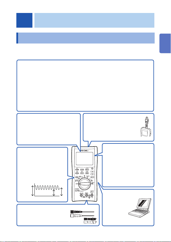
1.1 Overview and Features
This measuring instrument is a multi-function, high-precision digital
multimeter which ensures both safety and durability.
Main features
• Speedy display of the RMS measured value
• Environmental performance (can be used
anywhere) (Operation temperature: -15 to 55°C)
• High noise-proof performance
• Filter function effective for the inverter measurement
• Solid body which can be used for an extended
period of time (drop-proof)
• High accuracy (DCV: 0.025%), wide band (20 Hz to 100 kHz) measurement
• Speedy measurement via a fast response (0 V 100 V response 1 second*)
* Until the value falls within the accuracy specifi cation range.
If there is an excessive input,
a hazard is indicated by the
red display.
Large, easily-viewable display
Backlighting for use in dark
environments
For the DC power
supply maintenance
The peak measurement
function is used to
capture the ripple voltage
superimposed on the DC
signal.
PEAK max
The measurement test
leads and the end pins can
be selected depending on
the purpose of use.
PEAK min
100V85.9V114.1V
Problem fi nding a
suitable installation
location?
The strap with magnet allows the
device to be hung conveniently.
Useful functions during
measurement
• Noise reduction (FILTER)
• Display stability (SLOW)
• Display hold (HOLD)
• Maximum/Minimum value
display
Memorizing
measured values
For control of the UPS
battery cell voltage, etc.,
the measurement value can
be saved to the embedded
memory (up to 400 data).
The measurement value can
also be read.
Data transmission
to PC,
control
The optional
DT4900-01
Communication
Package is required.
1
2
3
4
5
6
7
Appx. Ind.
15
Parts Names and Functions
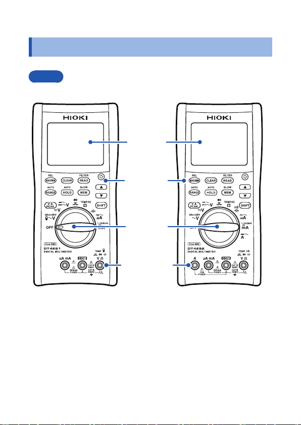
1.2 Parts Names and Functions
Front
Some indications are different between the DT4281 and DT4282.
Display
(p. 21)
Operation
keys (p. 17)
Rotary
switch
(p. 18)
Measurement
terminals
(p. 19)
DT4281 DT4282
16
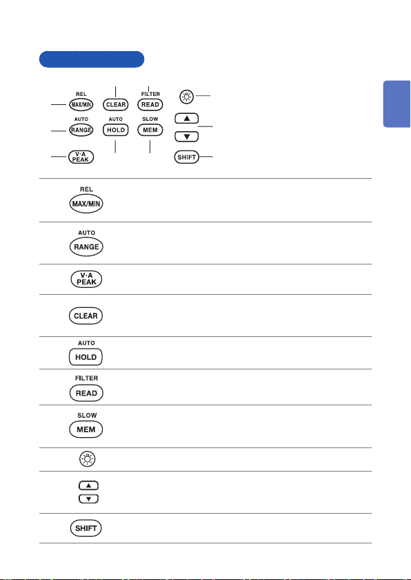
Operation keys
46
1
2
3
5
Parts Names and Functions
(*) Pressing a key for at
8
least 1 second activates
the function indicated
9
above the key
the function, change the
rotary switch setting.
7
10
. To disable
1
2
10
1
2
3
4
5
6
7
8
9
• Displays the maximum or minimum value. (p. 61)
• (*) activates the relative value display function. (p. 63)
• Selects the range (manual range). (p. 55)
• (*) changes to the auto range.
(The default is the auto range.)
Changes to the peak measurement. The maximum or
minimum instantaneous value is measured. (p. 62)
• Deletes the stored data. (p. 68)
• Clears the maximum or minimum value. (p. 61)
• Clears the peak value. (p. 62)
• Retains the displayed value. (p. 57)
• (*) activates the auto hold function.
• Reads the stored data. (p. 67)
• (*) toggles the fi lter function between on and off. (p. 60)
• Saves the measurement data. (p. 65)
• (*) toggles the display update speed between normal and
slow. ([SLOW] is used to stabilize the display.) (p. 59)
Turns on or off the display backlighting. (p. 69)
Increases/Decreases the memory No. or numeric value.
(When / are displayed on the LCD, these keys can be
operated.)
Changes the function of the rotary switch to that indicated
shown in blue.
3
4
5
6
7
Appx. Ind.
17
Parts Names and Functions
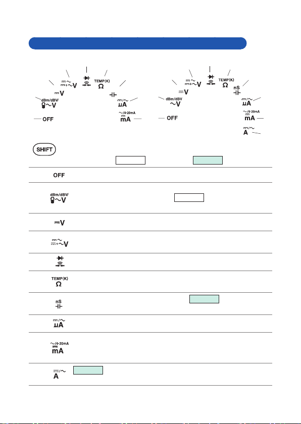
Rotary switches and measurement descriptions
5
4
3
2
1
6
7
3
8
2
9
1
DT4281
is used to change to the measurement shown in blue.
DT4281
: DT4281 only,
10
(
1
2
3
4
5
6
7
8
9
Turns off the power to the instrument.
AC voltage measurement (p. 38) dBm measurement
dBV measurement (p. 41)
measurement (p. 51)
DC voltage measurement (p. 39)
Synthesized voltage measurement of DC and AC Voltage
measurement of AC and DC components (p. 39)
Continuity check (p. 42) Diode test (p. 43)
Resistance measurement (p. 44) Tem pe rat ur e
measurement (compatible with the Thermocouples (K)) (p. 45)
Capacitance measurement (p. 47)
measurement (p. 48)
(6000 A range) DC measurement AC measurement (p. 49)
(600 mA range) DC measurement AC measurement (p. 49)
% conversion of the 4-20 mA input (The % conversion of the
0-20 mA input can be specifi ed via the power-on option.) (p. 53)
(10 A range)
DT4282
DC measurement AC measurement (p. 49)
4
DT4282
DT4281
DT4282
5
DT4282
: DT4282 only)
Clamp current
Conductance
6
7
8
9
10
18
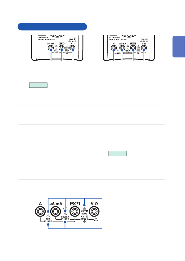
Parts Names and Functions
Measurement terminals
12 3 4234
DT4281 DT4282
DT4282
1
Current measurement (A) terminal. The red test lead is connected.
When the rotary switch is set to the current measurement, the shutter
opens.
Current measurement (A, mA) terminal. The red test lead is
2
connected. When the rotary switch is set to the current measurement,
the shutter opens.
Commonly used for each measurement. The black test lead is
3
connected.
Used for voltage measurement, resistance measurement, continuity
4
check, diode test, temperature measurement, clamp current
measurement
referred to as “V terminal”.
The red test lead is connected.
When the rotary switch is set to any of the measurements above, the
shutter of the current measurement terminal is closed.
DT4281
, or conductance
DT4282
. Hereafter
1
2
3
4
5
6
Be sure to carefully read the precautions in the following references.
See “Precautions during
measurement” (p. 12).
See “Replacing Fuses”
(p. 106).
19
7
Appx. Ind.
Parts Names and Functions
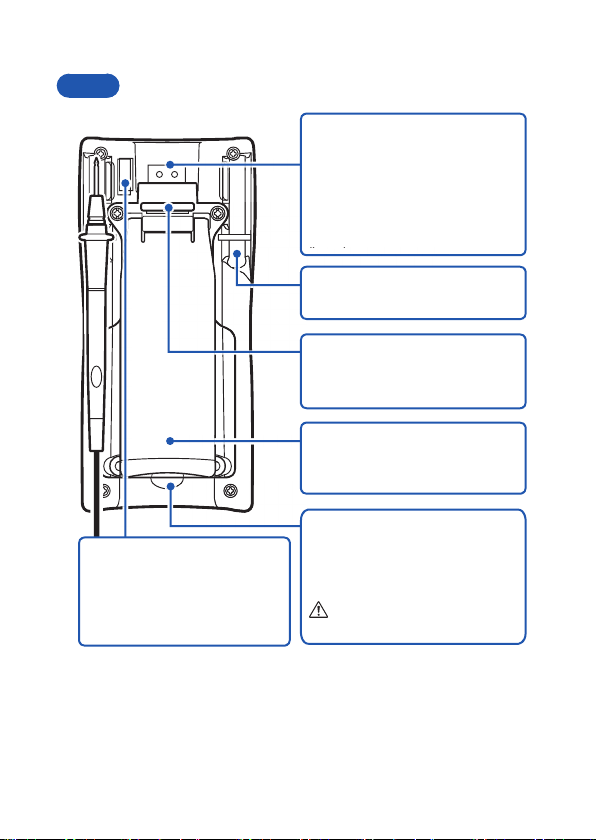
(p )
Rear
Serial number label
It is necessary for production
control such as product
warranty.
Do not peel off the label.
Communication port
When the communication
adapter supplied with the optional
DT4900-01 Communication
Package is connected, the data
can be transmitted to the PC.
(p. 72)
Test lead holder
The test lead can be held.
Strap hole
The optional Z5004 Magnetic
Strap can be attached. (p. 31)
Stand
The instrument can be set on the
stand. (p. 31)
Battery cover
When replacing the batteries
(p. 26) or fuse (p. 106), remove
the cover.
See p. 26.
20
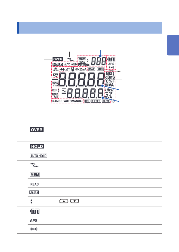
1.3 Display
For error displays, see “6.3 Error Display” (p. 105).
4
Memory No.
89
3
1
2
11
10
Blinks if the maximum value in each range is
1
2
3
4
5
exceeded. (Voltage, current, continuity, diode,
resistance, temperature, electrostatic capacity,
conductance)
Holds measured value. (p. 57)
The auto hold function is activated. (p. 57)
Communicating with the PC. (p. 72)
The memory function is activated. (p. 65)
Memory reading state (p. 67)
Stored data exist. (p. 65)
/ can be operated. (p. 65)
Battery indicator (p.24)
The auto power save function is activated. (p. 70)
The buzzer can be used. (p. 69)
5
6
7
Main display
Sub display
Display
1
2
3
4
5
6
7
Appx. Ind.
21
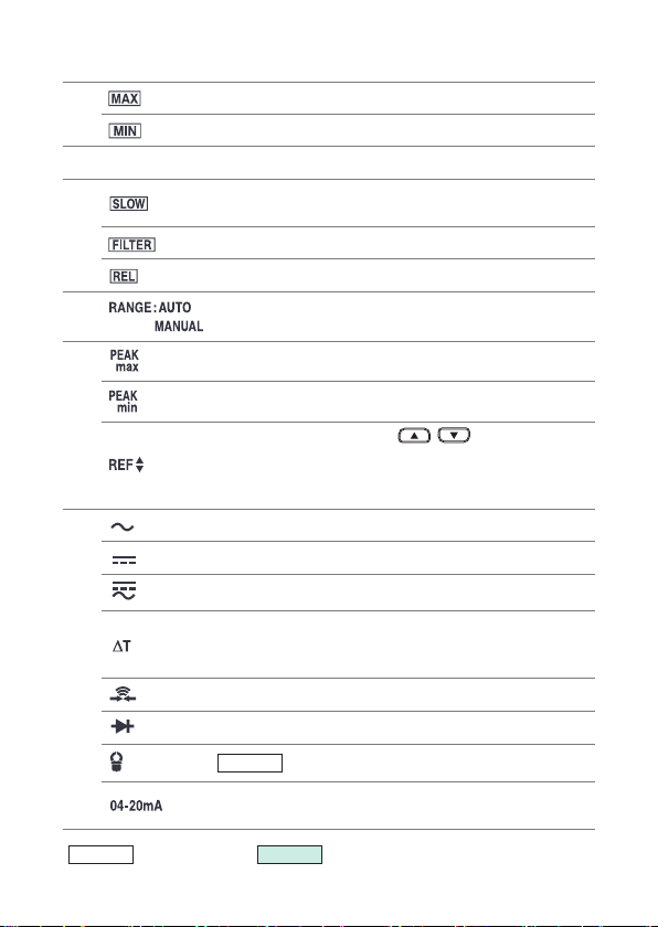
Display
6
(Unit) Each unit
7
8
9
10
11
Maximum value (p. 61)
Minimum value (p. 61)
The display update (sampling) is performed at SLOW
speed. (p. 59)
The fi lter function is activated. (p. 60)
The relative value display function is activated. (p. 63)
Auto range (p. 55)
Manual range (p. 55)
Maximum value in the peak measurement (p. 62)
Minimum value in the peak measurement (p. 62)
When are displayed, / can be used to
change values.
Threshold of the continuity check (p. 42)
Threshold of the diode test (p. 43)
AC measurement
DC measurement
AC measurement + DC measurement
During the temperature measurement, the
temperature difference from the standard is displayed.
(p. 45)
Continuity check (p. 42)
Diode test (p. 43)
Clamp current measurement (p. 51)
DT4281
% conversion measurement of 4-20 mA (0-20 mA)
(p. 53)
DT4281
(
22
: DT4281 only,
DT4282
: DT4282 only)
Alarm Display and Battery Indicator
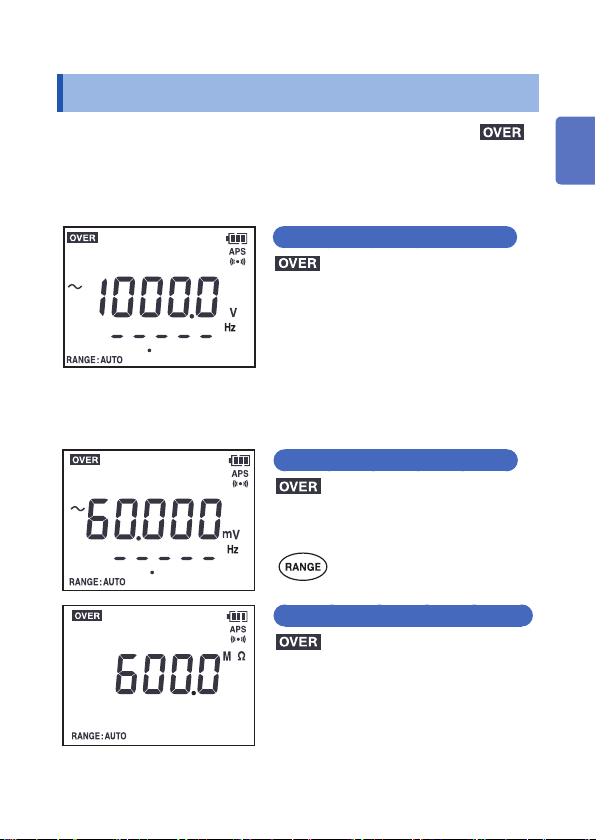
1.4 Alarm Display and Battery Indicator
The following conditions are informed via the red backlight,
display, and buzzer.
When the maximum input range is exceeded
Voltage/Current measurement
blinks, the red backlight blinks,
the maximum value within the maximum
range blinks, and the buzzer sounds.
Corrective action:
Immediately move the test leads away
from the measurement object.
When the measured value exceeds the maximum value
in each range ( Range over)
Voltage/Current measurement
blinks, the red backlight lights up,
and the maximum value blinks.
1
2
3
4
5
Corrective action:
and the maximum value blinks.
Change the range.
Measurements other than voltage and current
6
7
Appx. Ind.
Corrective action:
Change the range, or measure the
samples in the specifi ed range.
If the same symptom still occurs, check
that the test leads are not broken.
(p.34)
23
Alarm Display and Battery Indicator
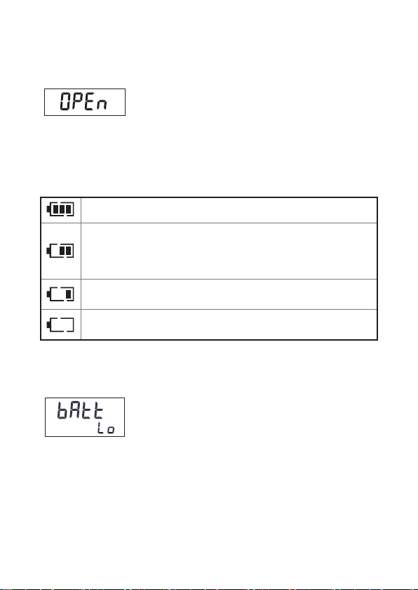
When the Thermocouple (K) is broken (Temperature
measurement)
Corrective action:
Check that the thermocouple has been connected
correctly to the measurement terminal. If the display
does not change, replace with a new Thermocouple
(K). (p. 45)
Battery indicator
Fully charged. (Charge: 60% or more)
As the battery charge diminishes,
black charge bars disappear, one
by one, from the left of the battery
indicator.
The battery voltage is low. Replace the
batteries as soon as possible.
(Blinks) The battery is exhausted.
Replace the batteries.
The charge is only a reference for the continuous operation time. (p. 96)
(Charge: 20% or more)
(Charge: 5% or more)
(Charge: less than 5%)
Power shutdown
When the charge is 0% (less than 3.8 V ± 0.2 V),
[bAtt Lo] is displayed for 1 second and the power is
shut down.
24
Preparation for Measurements
2
3
1
2
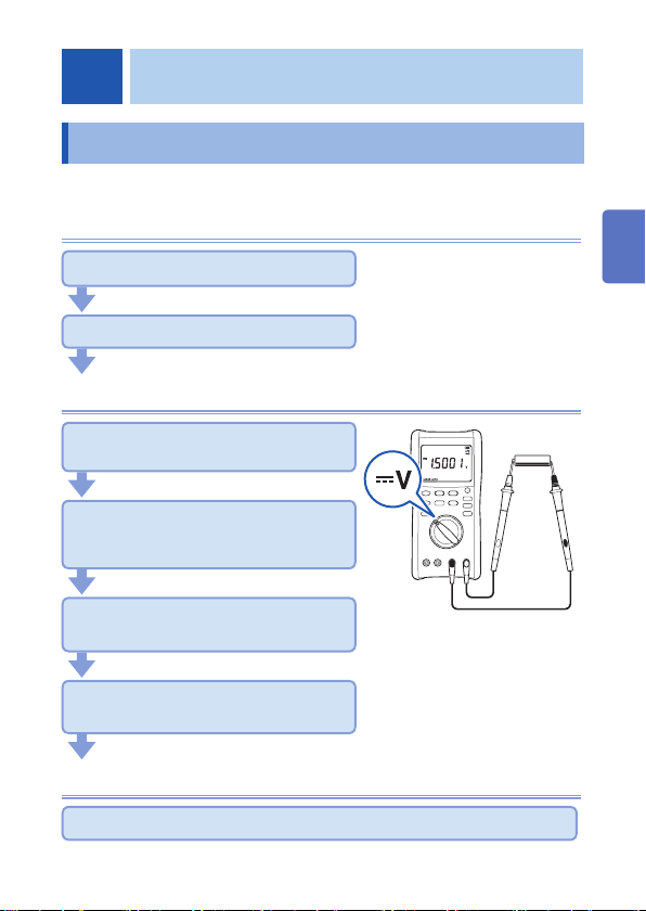
2.1 Measurement Workfl ow
Before using the instrument, be sure to read “Usage Notes” (p. 10).
Installation and connection
Insert the batteries. (p. 26)
Perform the startup check. (p. 33)
Measurement
Turn on the power and select the
measurement function.
Attach the test leads to the
measurement terminals. (p. 28)
(As necessary, perform zero adjustment. (p. 64))
Connect the test leads to the
measurement object.
(As necessary)
Hold the display of the measured value. (p. 57)
Save the measured value. (p. 65)
As necessary, have other
optional items available and
ready.
1
Black
2
Red
1
2
3
4
3
5
6
7
Appx. Ind.
End of the measurement
Move the test leads away from the measurement object and then turn off the power.
25
Inserting/Replacing Batteries
2.2 Inserting/Replacing Batteries
Before using the instrument fi rst time, insert four LR6 alkaline
batteries. Before measurements, check that the battery level is
suffi cient. When the battery charge diminishes, replace the batteries.
Nickel-metal hydride batteries
Nickel-metal hydride batteries can be used. However, the discharge
characteristic of these batteries is different from that of alkaline
batteries. Be aware that the remaining battery power display does
not function properly.
WARNING
To avoid electric shock, disconnect the test leads from
the object to be measured before replacing the batteries.
To avoid the possibility of explosion, do not short
circuit, charge, disassemble, or incinerate batteries.
After battery replacement but before using the
instrument, reattach and screw down the battery cover.
CAUTION
Poor performance or damage from battery leakage
could result. Observe the cautions listed below.
• Do no mix new and old batteries, or different types of
batteries.
• Be careful to observe the battery polarity during installation.
• Do not use batteries after their recommended expiry date.
• Do not allow used batteries to remain in the instrument.
• To avoid corrosion from battery leakage and/or damage to
the instrument, remove the batteries from the instrument
if it is to be kept in storage for an extended period.
26
 Loading...