


DT4250 Series
DIGITAL MULTIMETER
Remote Operation Manual
HIOKI E. E. CORPORATION
May, 2015
Edition 2

DT4250 series DIGITAL MULTIMETER Remote Operation Manual
Contents
1. Remote Interface Overview .............................................................. 3
2. Interface Parameters ........................................................................ 3
3. About Command ............................................................................... 4
3.1. Terminator ...................................................................................................... 4
3.2. Return result .................................................................................................. 4
3.3. Data Types ...................................................................................................... 4
4. Summary of Commands ................................................................... 5
5. Detail of Commands ......................................................................... 6
5.1. Description of Commands .............................................................................. 6
5.2. Combination response string function and range ....................................... 10
5.3. Count value of abnormal data ...................................................................... 11
6. Compatible command with earlier products ................................. 11
P2/11

DT4250 series DIGITAL MULTIMETER Remote Operation Manual
1. Remote Interface Overview
Step1. Connect the USB cable to the USB port on the computer.
Step2. Once the USB cable is connected and the USB driver is installed, a virtual COM port
is created on the computer.
2. Interface Parameters
In order to operate the meter via a host computer or terminal, the parameters in interface
within the DT4251,DT4252,DT4253,DT4254,DT4255,DT4256 have to match the parameters
the serial interface provided by the host or terminal.
The following procedures will guide to set up interface parameters within these models.
Table.1
Item
1 Baud Rate 9600 bps
2 Data Length 8 bit
3 Parity Check None
4 Stop Bit 1 bit
Parameter Setting
P3/11
DT4250 series DIGITAL MULTIMETER Remote Operation Manual
3. About Command
3.1. Terminator
A terminator is a character sent by a host, which identified the end of a command string.
A valid terminator consists of two-byte data.
<CR> (Carriage Return, ASC(&H0D) )
<LF> (Line Feed, ASC(&H0A) )
3.2. Return result
After execution of query command, digital multimeter will return the following format.
<Result> + <CR> <LF>
3.3. Data Types
Returned message is the ASCII string from the digital multimeter responding to a query.
Table.2
Data Type Explanation Example
<NR1> An integer +10000, -10000, 123, -100
<NR2> This numeric representation has an
explicit radix point.
+13.234, -.00002, 3.4567
<NR3> This representation has an explicit
radix point and an exponent.
<Boolean> String ASCII-encoded byte, is return
for the setting query.
<Literal> ASCII string ACV, DCV
P4/11
-1.000000E+02
0 or 1

DT4250 series DIGITAL MULTIMETER Remote Operation Manual
4. Summary of Commands
Table.3
Command Parameter Description
QPID Query the Meter model.
*IDN Query the Meter identification.
:SYST:RST Put the meter to reset.
:SYST:LLO Put the meter into the local lockout state.
:SYST:GTL Put the meter into the local state.
:CONF? Query the main function of the display.
:CONF2? Query the sub function of the display.
:CONF <function,range> Configure the function and range.
:FETCCNT? Query main measured count value.
:FETCCNT2? Query sub measured count value.
:CALC:STAT:MAX? Query measured maximum count value.
:CALC:STAT:MIN? Query measured minimum count value.
:CALC:STAT: AVER? Query measured average count value.
:CALC:REL:OFFS? Query the offset value of the relative.
:SYST:APS <0|1> Set the APS.
:SYST:BEEP <0|1> Set the action of the beeper.
:SYST:BLIT <0|1> Set the backlight.
:SYST:BLA <0|1> Set the auto backlight.
:SYST:BATT? Query the battery level.
:SYST:REL <0|1> Set the relative.
:SYST:FILTER <0|1>,<100|500> Set the filter.
:MEAS:AUTOV? Query the status DC or AC of AutoV function.
:SYST:INIT Put the meter to power-on-reset state.
:STAT? Query the status of the meter.
P5/11

DT4250 series DIGITAL MULTIMETER Remote Operation Manual
5. Detail of Commands
5.1. Description of Commands
The DT4251,DT4252,DT4253,DT4254,DT4255,DT4256 only accepts the UPPERCASE
command. (Except Unit etc.)
Table.4
Command Explanation
QPID Query the Meter model.
Syntax QPID
Response “DT4251” or “DT4252” or “DT4253” or ”DT4254”
or “DT4255” or “DT4256”
*IDN Query the Meter identification.
Syntax *IDN?
Response <data×3>
<data> maker name, model number, serial, version
Example; “HIOKI,DT4251,130501234,Ver 1.00”
:SYST:RST Put the meter to reset.
Syntax :SYST:RST
Response “OK”
:SYST:LLO Put the meter into the local lockout state.
Syntax :SYST:LLO
Response “OK”
:SYST:GTL Put the meter into the local state.
Syntax :SYST:GTL
Response “OK”
:CONF?
Query the function of the display.
:CONF2?
:CONF Configure the function and range.
Syntax :CONF? [:CONF2?]
Response <data×2>
<data> function,range
Example; “ACV, 600m”
→ 5.2 Combination response string function and range
Syntax :CONF <data×2>
<data> function,range
Example; “:CONF RES, 60k”
P6/11

DT4250 series DIGITAL MULTIMETER Remote Operation Manual
5.2 Combination response string function and range
→
Response “OK” or “CMD ERR” or “EXE ERR”
Command Explanation
:FETCCNT?
:FETCCNT2?
:CALC:STAT:MAX? Query measured maximum count value.
:CALC:STAT:MIN? Query measured minimum count value.
:CALC:STAT:AVER? Query measured average count value.
Query measured count value.
Syntax :FETCCNT? [:FETCCNT2?]
Response <data×1>
<data> count value
Example; “3000”
Syntax :CALC:STAT:MAX?
Response <data×1>
<data> count value
Example; “5000”
Syntax :CALC:STAT:MIN?
Response <data×1>
<data> count value
Example; “2000”
Syntax :CALC:STAT: AVER?
Response <data×1>
<data> count value
Example; “3500”
:CALC:REL:OFFS? Query the offset value of the relative.
Syntax :CALC:REL:OFFS?
Response <data×2>
<data> offset value, range
Example; “20, 600m”
:SYST:APS Set the APS.
Syntax :SYST:APS <data×1>
<data> “0” (off) or “1” (on)
Example; “:SYST:APS 1”
Response “OK” or “CMD ERR”
:SYST:BEEP Set the action of the beeper.
Syntax :SYST:BEEP <data×1>
<data> “0” (off) or “1” (on)
Example; “:SYST:BEEP 1”
Response “OK” or “CMD ERR”
P7/11

DT4250 series DIGITAL MULTIMETER Remote Operation Manual
Command Explanation
:SYST:BLIT Set the backlight.
Syntax :SYST:BLIT <data×1>
<data> “0” (off) or “1” (on)
Example; “:SYST:BLIT 1”
Response “OK” or “CMD ERR”
:SYST:BLA Set the auto backlight.
Syntax :SYST: BLA <data×1>
<data> “0” (off) or “1” (on)
Example; “:SYST: BLA 1”
Response “OK” or “CMD ERR”
:SYST:BATT? Query the battery level.
Syntax :SYST:BATT?
Response <data×1>
<data> Four steps remaining battery level.
“3” or “2” or “1” or “0”
:SYST:REL Set the relative.
Syntax :SYST: REL <data×1>
<data> “0” (off) or “1” (on)
Example; “:SYST: REL 1”
Response “OK” or “CMD ERR”
:SYST:FILTER Set the filter.
Syntax :SYST: FILTER <data×2>
<data1> “0” (off) or “1” (on)
<data2> “100” (100Hz) or “500” (500Hz)
Example; “:SYST: FILTER 1,100”
Response “OK” or “CMD ERR”
:MEAS:AUTOV? Query the status DC or AC of AutoV function.
Syntax :MEAS: AUTOV?
Response “0” (DC) or “1” (AC)
or “EXE ERR” (Other than AutoV function)
:SYST:INIT Put the meter to power-on-reset state.
Syntax :SYST: INIT
Response “OK”
P8/11

DT4250 series DIGITAL MULTIMETER Remote Operation Manual
Command Explanation
:STAT? Query the status of the meter.
Syntax :STAT?
Response “<ABCDEFGHIJKLMNOPQRSTUVWX>” (24char)
A---Recording “0”(OFF)
B---Relative value (REL) “0”(OFF) or “1”(ON)
C---Filter “0”(OFF) or “1”(ON)
D---Beep “0”(OFF) or “1”(ON)
E---APS “0”(OFF) or “1”(ON)
F---Battery level “0”~“3”
G---Input warning “0”(normal) or “1”(warn)
or “1”(MAX) or “2”(MIN) or “3”(AVG)
HI---Rotary position “00”~“99”(from OFF)
J---HOLD “0”(OFF) or “1”(ON)
K---Auto Hold “0”(OFF) or “1”(ON)
L---Auto Range “0”(OFF) or “1”(ON)
M---Backlight “0”(OFF) or “1”(ON)
N---Backlight Auto OFF “0”(OFF) or “1”(ON)
O---Filter Cut-off frequency “0”(100Hz) or “1”(500Hz)
P---reserved “0”
Q--- reserved “0”
R--- reserved “0”
S--- reserved “0”
T--- reserved “0”
U--- reserved “0”
V--- reserved “0”
W---reserved “0” or “1”
X---reserved “0”
P9/11

DT4250 series DIGITAL MULTIMETER Remote Operation Manual
5.2. Combination response string function and range
Table.5
Function Range
ACV 6, 60, 600, 1000
DCV
DCmV 600m
AutoV 600
CONT 600
RES 600, 6k, 60k, 600k, 6M, 60M
CAP 1u, 10u, 100u, 1m, 10m
DIODE 1500
TEMP 400
CLAMP 10, 20, 50, 100, 200, 500, 1000
ACA
DCA
DCmA 6m, 60m
DCuA 60u, 600u
VDET
FREQ 100, 1k, 10k, 100k
600m(※1), 6, 60, 600, 1000
600m(※2), 6, 10
60m(※3), 600m(※4), 6, 10
0 (Lo, Hi) (※5)
(※1)600mV range is for DT4251 or DT4253 or DT4254 or DT4255 or DT4256.
(※2)600mA range is only DT4256
(※3)60mA range is only DT4256
(※4)600mA range is only DT4256
(※5)1 is for DT4254 or DT4255 or DT4256
P10/11

DT4250 series DIGITAL MULTIMETER Remote Operation Manual
5.3. Count value of abnormal data
Response of count value query return the values shown in Table.6 in the case of abnormal data.
Table.6
Type of abnormal value Count value
Over Range value 1000000
Invalid data 2000000
Open value (DT4253, TEMP function) 3000000
Internal error value (DT4253, TEMP function) 4000000
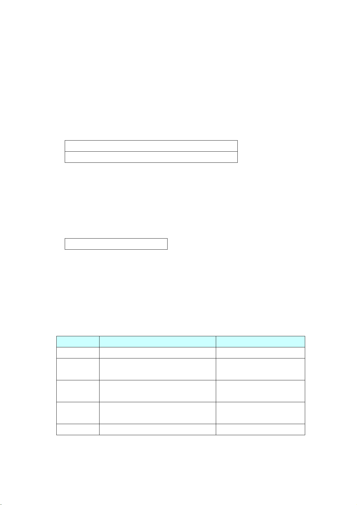
6. Compatible command with earlier products
Table.7 shows the command compatibility with earlier products 3800 series.
Table.7
Command Description
*CLS Clear the system Error Queue.
*RST Put the meter to power-on-reset state.
LLO Put the meter into the local lockout state when in remote
control. This means no local key operation at the front panel is
allowed during remote control.
GTL Put the meter into the local state, clearing the remote state and
front panel lockout.
FETC? [@2] Return the primary or secondary function value of output butter.
Response:<NR3>
P11/11
 Loading...