

DT4221
HIOKI DT4221A981-03
DT4222
Instruction Manual
DT4223
DT4224
DIGITAL MULTIMETER
July
2021 Revised edition 3
DT4221A981-03 21-07H
EN

HIOKI DT4221A981-03

Contents
HIOKI DT4221A981-03
Introduction ................................................................... 1
Verifying Package Contents ........................................ 1
Options (sold separately) ............................................ 2
Safety Notes .................................................................. 3
Usage Notes .................................................................. 8
1 Overview 13
1.1 Overview and Features ........................... 13
1.2 Parts Names and Functions ................... 15
1.3 Display ..................................................... 20
1.4 Voltage Input Protected
(DT4223, DT4224) .................................... 21
1.5 Alarm Display and Battery Indicator ..... 22
2 Preparation for Measurements 23
2.1 MeasurementWorkow .......................... 23
2.2 Inserting/Replacing the Battery ............. 24
2.3 Using Test Leads ..................................... 26
2.4 Installation in Measurement Location ... 29
Hanging the instrument with the strap ................29
3 Performing Measurements 31
3.1 Inspection Before Use ............................ 31
3.2 Measuring Voltage................................... 35
Measuring AC voltage .........................................35
Measuring DC voltage ........................................36
Measurement using the AC/DC automatic
judgment (DT4221, DT4223) ..............................36
3.3 Measuring Frequencies .......................... 37
DT4221A981-03
i

Contents
HIOKI DT4221A981-03
3.4 Checking Continuity ............................... 38
3.5 Measuring Diode (DT4222, DT4224) ...... 39
3.6 Measuring Resistance
(DT4222, DT4223, DT4224) ..................... 40
3.7 Measuring Capacitance
(DT4222, DT4224) .................................... 41
3.8 Checking the Electric Charge
(DT4221, DT4223) .................................... 42
4 Using Instrument Conveniently 43
4.1 Selecting the Measurement Range ........ 43
Measuring with the auto range ...........................43
Measuring with the manual range .......................44
4.2 Retaining the Measured Value ............... 45
Retaining the measured value manually
(HOLD) ...............................................................45
Automatically retaining the measured value
when the value stablizes (AUTO HOLD)
(DT4223, DT4224) ..............................................46
4.3 Reducing the Noise (FILTER) ................. 48
4.4 Checking the Relative Value/
Performing Zero Adjustment .................. 50
Checking the relative value (REL) ......................50
Performing zero adjustment ................................51
4.5 Turning On the Backlight ........................ 53
4.6 Using the Auto Power Save (APS) ......... 53
4.7 Power-on Option Table ........................... 54
5 Specications 57
5.1 GeneralSpecications ........................... 57
5.2 Electrical Characteristics ....................... 59
5.3 Accuracy Table ........................................ 61
ii

Contents
HIOKI DT4221A981-03
6 Maintenance and Service 67
6.1 Repair, Inspection, and Cleaning ........... 67
6.2 Troubleshooting ...................................... 68
6.3 Error Display ............................................ 70
Appendix Appx.1
Appx. 1 RMS and Average ....................... Appx.1
iii

Contents
HIOKI DT4221A981-03
iv

Introduction
9243 graber
L4937 マグネットアダプ
タ
L4934 小ワニグチ
DM4910 熱電対
DT4911TestLead
HIOKI DT4221A981-03
Introduction
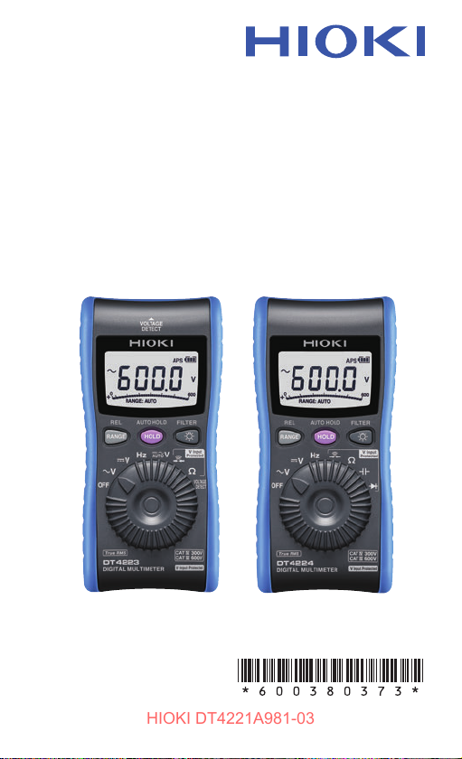
Thank you for purchasing the Hioki DT4221, DT4222, DT4223,
DT4224 Digital Multimeter. To obtain maximum performance
from the product, please read this manual rst, and keep it
handy for future reference.
Verifying Package Contents
When you receive the instrument, inspect it carefully to ensure
that no damage occurred during shipping. In particular, check
the accessories, panel switches, and connectors. If damage is
evident, or if it fails to operate according to the specications,
contact your authorized Hioki distributor or reseller.
Check the package contents as follows.
Instrument
(The holster has been attached.)
DT4911 Test Lead (p. 26)
LR03 Alkaline battery
DT4221
DT4224
DT4222
DT4223
Instruction Manual
(English)
Instruction manuals may
also be available in other
languages.
Please visit our website at
http://www.hioki.com
1

Options (sold separately)
9243 graber
DM4910 熱電対
DT4911TestLead
9243 graber
L4937 マグネットアダプ
タ
L4934 小ワニグチ
マグネ付ストラップ
L9207-10
DM4910 熱電対
DT4911TestLead
DT4912TestLead
L4930 接続ケーブル
L4931renketu
L4931 延長ケーブル
L4932(+9207-10cap)
L4933 コンタクトピン
L4937 マグネットアダプ
タ
L4934 小ワニグチ
HIOKI DT4221A981-03
Options (sold separately)
The options listed below are available for the instrument. To
order an option, please contact your authorized Hioki distributor
or reseller. Options are subject to change. Please check Hioki’s
website for the latest information.
Connecting cables (p. 26)
L4933
Contact Pin Set
V DC
AC/60
L4934
Small Alligator Clip Set
DT4911
Test Lead
C0200 Carrying Case
The instrument, test leads, instruction manual, and
others can be stored in the case.
V
30
CAT III 300 V/CAT II 600 V
Z5004, Z5020 Magnetic Strap (p. 29)
2
Attach this strap to the instrument and secure it on
the wall surface such as a metal plate for use.

Safety Notes
HIOKI DT4221A981-03
Safety Notes
This instrument is designed to conform to IEC 61010 Safety
Standards, and has been thoroughly tested for safety prior to
shipment. However, using the instrument in a way not described
in this manual may negate the provided safety features.
Before using the instrument, be certain to carefully read the
following safety notes.
DANGER
Mishandling during use could result in injury or
death, as well as damage to the instrument. Be
certain that you understand the instructions and
precautions in the manual before use.
WARNING
With regard to the electricity supply, there are
risks of electric shock, heat generation, re, and
arc discharge due to short circuits. If persons
unfamiliar with electricity measuring instruments
are to use the instrument, another person familiar
with such instruments must supervise operations.
Protective gear
To avoid electric shock when measuring live lines,
wear appropriate protective gear, such as insulated
rubber gloves, boots and a safety helmet.
WARNING
3
Safety Notes
HIOKI DT4221A981-03
Notation
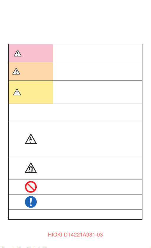
In this manual, the risk seriousness and the hazard levels are
classied as follows.
Indicates an imminently hazardous situation
DANGER
WARNING
CAUTION
IMPORTANT
that will result in death or serious injury to the
operator.
Indicates a potentially hazardous situation
that may result in death or serious injury to the
operator.
Indicates a potentially hazardous situation
that may result in minor or moderate injury to
the operator or damage to the instrument or
malfunction.
Indicates information related to the operation
of the instrument or maintenance tasks with
which the operators must be fully familiar.
Indicates a high voltage hazard.
If a particular safety check is not performed or
the instrument is mishandled, this may give
rise to a hazardous situation; the operator may
receive an electric shock, may get burnt or
may even be fatally injured.
Indicates a strong magnetic-eld hazard.
The effects of the magnetic force can cause
abnormal operation of heart pacemakers and/
or medical electronics.
*
4
Indicates prohibited actions.
Indicates the action which must be performed.
Additional information is presented below.

Safety Notes
・
HIOKI DT4221A981-03
Symbols afxed to the instrument
Indicates cautions and hazards. When the symbol is printed
on the instrument, refer to a corresponding topic in the
Instruction Manual.
Indicates that dangerous voltage may be present at this
terminal.
Indicates a double-insulated device.
Indicates a grounding terminal.
Indicates DC (Direct Current).
Indicates AC (Alternating Current).
Indicates DC (Direct Current) or AC (Alternating Current).
Symbols for various standards
Indicates the Waste Electrical and Electronic Equipment
Directive (WEEE Directive) in EU member states.
Indicates that the instrument conforms to regulations set out
by the EC Directive.
Screen display
This instrument uses the following screen displays.
A B C D E F G H I J K L M N O P Q R S T U V W X Y Z
1 2 3 4 5 6 7 8 9 0
5

Safety Notes
HIOKI DT4221A981-03
Accuracy
We dene measurement tolerances in terms of rdg. (reading)
and dgt. (digit) values, with the following meanings:
(Reading or displayed value)
rdg.
The value currently being measured and indicated on the
measuring instrument.
(Resolution)
The smallest displayable unit on a digital measuring
dgt.
instrument, i.e., the input value that causes the digital
display to show a “1” as the least signicant digit.
6
Safety Notes
HIOKI DT4221A981-03
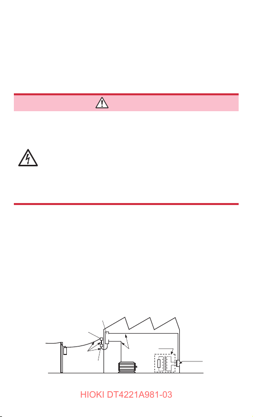
Measurement categories
To ensure safe operation of measuring instruments, IEC 61010
establishes safety standards for various electrical environments,
categorized as CAT II to CAT IV, and called measurement
categories.
DANGER
• Using a measuring instrument in an environment
designated with a higher-numbered category
than that for which the instrument is rated
could result in a severe accident, and must be
carefully avoided.
• Using a measuring instrument without
categories in an environment designated with
the CAT II to CAT IV category could result in a
severe accident, and must be carefully avoided.
This instrument conforms to the safety requirements for CAT III 600 V,
CAT IV 300 V measuring instruments.
CAT II: When directly measuring the electrical outlet receptacles of
the primary electrical circuits in equipment connected to an
AC electrical outlet by a power cord (portable tools, household
appliances, etc.)
CAT III: When measuring the primary electrical circuits of heavy equipment
(xed installations) connected directly to the distribution panel,
and feeders from the distribution panel to outlets
CAT IV: When measuring the circuit from the service drop to the service
entrance, and to the power meter and primary overcurrent
protection device (distribution panel)
Distribution panel
Service entrance
Service drop
CAT IV
Power meter
See: “2.3 Using Test Leads” (p. 26)
Internal wiring
CAT III
Fixed installation
CAT II
T
Outlet
7

Usage Notes
HIOKI DT4221A981-03
Usage Notes
Observe the following precautionary information to ensure
that the instrument can be used safely and in a manner that
allows it to perform as described in its specications. Use of the
instrument should conrm not only to its specications, but also
to the specications of all accessories, options, batteries, and
other equipment in use.
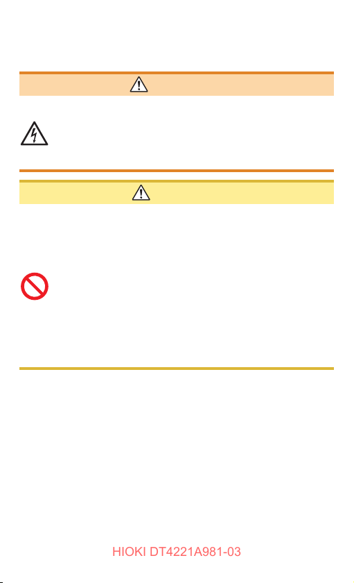
DANGER
If the test lead or the instrument is damaged,
there is a risk of electric shock. Before using the
instrument, perform the following inspection.
• Before using the instrument, check that the
coating of the test leads are neither ripped nor
torn and that no metal parts are exposed. Using
the instrument under such conditions could
result in electrocution. Replace the test leads
with those specied by our company.
• Before using the instrument the rst time, verify
that it operates normally to ensure that no
damage occurred during storage or shipping. If
you nd any damage, contact your authorized
Hioki distributor or reseller.
8

Usage Notes
HIOKI DT4221A981-03
Installation
Installing the instrument in inappropriate locations may cause a
malfunction of instrument or may give rise to an accident. Avoid
the following locations.
CAUTION
• Exposed to direct sunlight or high temperature
• Exposed to corrosive or combustible gases
• Exposed to water, oil, chemicals, or solvents
• Exposed to high humidity or condensation
• Exposed to a strong electromagnetic eld or
electrostatic charge
• Exposed to high quantities of dust particles
• Near induction heating systems (such as highfrequency induction heating systems and IH cooking
equipment)
• Susceptible to vibration
9

Usage Notes
HIOKI DT4221A981-03
Handling the cables
WARNING
To prevent electric shock, when measuring the
voltage of a power line use a test lead that satises
the following criteria:
• Conforms to safety standards IEC61010 or EN61010
• Of measurement category III or IV
• Its rated voltage is higher than the voltage to be
measured
All of the optional test leads for this instrument
conform to the safety standard EN61010. Use a test
lead in accordance with its dened measurement
category and rated voltage.
To avoid electric shock, do not exceed the lower of
the ratings shown on the instrument and test leads.
CAUTION
• Avoid stepping on or pinching the cable, which could
damage the cable insulation.
• To avoid damaging the cables, do not bend or pull the
leads and the probe bases.
The ends of the test leads are sharp. Be careful to avoid
injury.
10
Precautions during measurement
HIOKI DT4221A981-03
WARNING
If the instrument is used in locations where the
rating indicated on the instrument or probes is
exceeded, the instrument may be damaged resulting
in personal injury. Do not use the instrument in such
locations. See “Measurement categories” (p. 7).
CAUTION
• Do not input voltage exceeding the specied
measurement range. Doing so may damage the
instrument.
• During the continuity check, diode test, or measurement
of resistance or capacitance, measurement signals are
generated in the terminals of the instrument. Depending
on the target for measurement, the measurement signal
may cause damage.
Seeing “Measurement current” and “Open circuit
voltage” in the accuracy table (p. 61), check, in
advance, that there are no adverse effects of the
measurement current and the open circuit voltage.
Usage Notes
11

Usage Notes
HIOKI DT4221A981-03
Precautions during shipment
Observe the following during shipment. Hioki cannot be
responsible for damage that occurs during shipment.
CAUTION
• During shipment of the instrument, handle it carefully
so that it is not damaged due to a vibration or shock.
• To avoid damage to the instrument, remove the
accessories and optional equipment from the
instrument before shipment.
If the instrument is not to be used for an extended
period of time
IMPORTANT
To avoid corrosion and/or damage to the instrument due to
battery leakage, remove the battery from the instrument if it is
to be kept in storage for an extended period.
12

Overview
HIOKI DT4221A981-03
1
1.1 Overview and Features
This measuring instrument is a multi-function digital multimeter
that ensures both safety and durability.
Main features and functions
• Speedy display of the RMS measured value
• Environmental performance (can be used anywhere)
(Operation temperature: DT4221, DT4222: −10 to 50°C
• Filter function that controls the inuence of noise
• Hold function that retains the screen display
• Solid body which can be used for an extended period of time (drop-proof)
• Speedy measurement via a fast response*
* Response time of 0 V to 100 V is approx. 0.6 seconds
(until the value falls within the accuracy specication range)
• Voltage input protection function to ensure safe measurement (DT4223,
DT4224)
Protective circuitry to ensure safety in the event of voltage measurement
using the continuity, resistance, capacitance, or diode range (Voltage
Input Protected)
Red backlight to warn user of erroneous voltage input
• Protective circuitry operates in the event of erroneous voltage input to
limit the amount of current owing to the instrument to 1.5 mA or less.
• This safe design keeps circuit breakers from tripping and sparks from
being produced at the tips of test leads.
• Although the DT4221 and DT4222 will not break if they are used to
measure voltage in continuity, resistance, capacitance, or diode range,
those models do not provide functionality to limit the amount of current
owing to the instrument in the event of such measurement to 1.5 mA
or less, or to warn the user of erroneous voltage input by turning the
backlight red.
DT4223, DT4224: −10 to 65°C)
13

Overview and Features
9243 graber
L4937 マグネットアダプ
タ
L4934 小ワニグチ
DM4910 熱電対
DT4911TestLead
9243 graber
L4937 マグネットアダプ
タ
L4934 小ワニグチ
マグネ付ストラップ
L9207-10
DM4910 熱電対
DT4911TestLead
DT4912TestLead
L4930 接続ケーブル
L4931renketu
L4931 延長ケーブル
L4932(+9207-10cap)
L4933 コンタクトピン
L4937 マグネットアダプ
タ
L4934 小ワニグチ
HIOKI DT4221A981-03
Problem nding a suitable
installation location?
The strap with magnet allows
the instrument to be hung
conveniently.
Large, easilyviewable display
Backlighting to allow
users to read the
measurement values in
dark environments
For various
purposes
The measurement
test leads and end
pins can be selected.
14
Parts Names and Functions
HIOKI DT4221A981-03
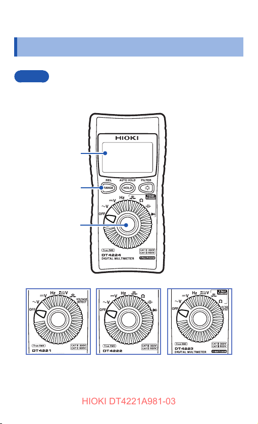
1.2 Parts Names and Functions
Front
Some indications are different among the models.
Display
(p. 20)
Operation keys
(p. 16 )
Rotary switch
(p. 18)
DT4224
DT4221 DT4222 DT4223
15
Parts Names and Functions
5 6 7 8 9
5 6 7 8 9
HIOKI DT4221A981-03
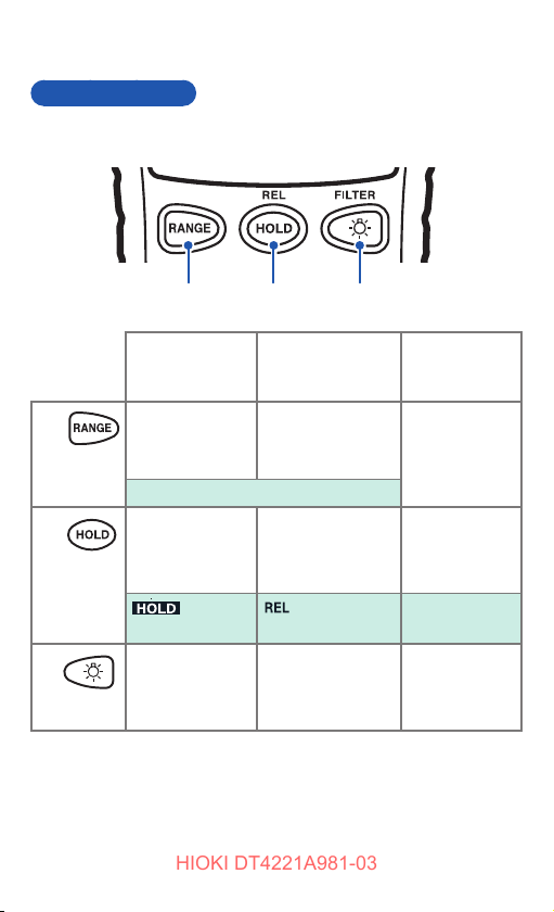
Operation keys
DT4221, DT4222
11 22
Normal
11
22
33
16
Sets the manual
range/switches
the range.
Manually sets/
cancels the hold
function for the
displayed value.
lights up/
goes off.
Turns on/off the
backlight.
33
Pressed down
for at least 1
second
Cancels the manual
range.
Sets/cancels the
display of the
relative value
(REL).
lights up/goes
off.
Switches/cancels
the low pass lter
and passband
settings.
Poweron option
(p. 54)
All LCDs
light up and
the software
version is
displayed.RANGE:AUTO / RANGE:MANUAL
Cancels the
auto power save
function (APS).
APS goes off.
Turns off the
automatic
backlight
deactivation.

DT4223, DT4224
5 6 7 8 9
5 6 7 8 9
5 6 7 8 9
5 6 7 8 9
HIOKI DT4221A981-03
Parts Names and Functions
Normal
11
22
33
Sets the auto and
manual range/
switches the
range.
RANGE:AUTO / RANGE:MANUAL
Manually sets/
cancels the hold
function for the
displayed value.
lights up.
Turns on/off the
backlight.
11 22
Pressed down
for at least 1
second
Sets/cancels the
display of the
relative value
(REL).
Automatically
sets/cancels the
hold function for
the displayed
value.
Switches/cancels
the low pass lter
and passband
settings.
blinks.
33
Poweron option
(p. 54)
All LCDs light up.
The software
version and
serial number is
displayed.
Cancels the
auto power save
function (APS).
APS goes off.
Turns off the
automatic
backlight
deactivation.
17
Parts Names and Functions
HIOKI DT4221A981-03
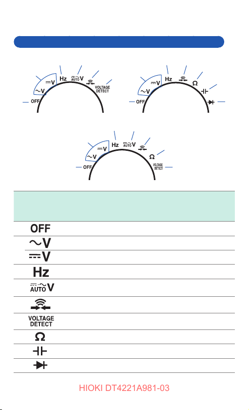
Rotary switches and measurement descriptions
44
33
22
11
DT4221
55
22
66
11
DT4222, DT4224
44
33
22
55
55
33
77
88
99
77
11
DT4223
Function
66
DT4221
DT4222
DT4224
DT4223
11
22
33
44
55
66
77
88
99
AC voltage measurement
DC voltage measurement
Frequency measurement
DC/AC voltage measurement
(Automatic judgment)
Continuity check
Electric charge detection
Resistance measurement
Capacitance measurement
Diode test
√ √ √
√ √ √
√ √ √
√ − √
√ √ √
√ − √
− √ √
− √ −
− √ −
18
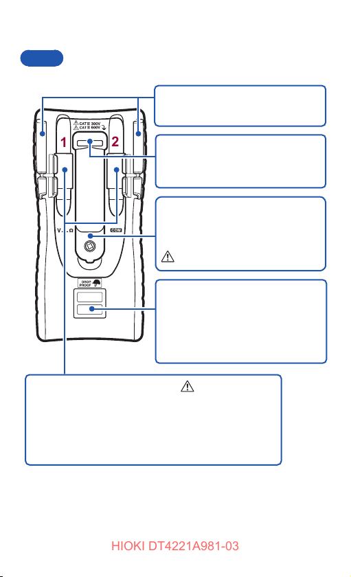
Rear
HIOKI DT4221A981-03
Parts Names and Functions
DT4224
Test lead holder
The test lead can be held.
11
Measurement terminals
The red test lead is connected.
11
Hereafter referred to as “V terminal”.
The black test lead is connected.
22
Hereafter referred to as “COM terminal”.
22
Strap hole
The optional Z5004, Z5020 Magnetic
Strap can be attached. (p. 29)
Battery cover
When replacing the battery (p. 24),
remove the cover.
Serial number label
The rst four digits of the 9-digit
number indicate the year (the rst
two digits omitted) and the month of
manufacture. Do not remove this label
as the number is important.
(See p. 24)
(See p. 28)
19

Display
5 6 7 8 9
10
11
1
2
4
3
5 6 7 8 9
10
11
1
2
4
3
5 6 7 8 9
5 6 7 8 9
5 6 7 8 9
5 6 7 8 9
5 6 7 8 9
5 6 7 8 9
5 6 7 8 9
5 6 7 8 9
5 6 7 8 9
5 6 7 8 9
5 6 7 8 9
10
11
5 6 7 8 9
10
11
5 6 7 8 9
10
5 6 7 8 9
10
HIOKI DT4221A981-03
1.3 Display
For error displays, see “6.3 Error Display” (p. 70).
5 6 7 8 9
1
2
3
4
11
22
33
44
55
66
77
20
AC/DC automatic
judgment *
When the input
impedance is low
for continuity/
resistance/
capacitance/
diode.*
AC, DC
Continuity check
(p. 38)
Diode (p. 39)
Retention of the
measured value
(p. 45)
Relative value
display (p. 50)
The lter function
is activated.
(p. 48)
1
2
88
99
Indication (example): In the
1010
case of 30 V input in the 60 V
range, the bar is displayed to
the center of the scale.
Auto range, manual range
1111
(p. 43)
*1: DT4221
*2: DT4223, DT4224
10
11
The auto power
save function
is activated.
(p. 53)
Battery indicator
(p. 21)

Voltage Input Protected (DT4223, DT4224)
HIOKI DT4221A981-03
1.4 Voltage Input Protected (DT4223, DT4224)
Erroneous voltage warning for continuity, resistance,
capacitance, or diode range
The red backlight ashes to warn the user. Immediately move
the test leads away from the measurement object.
Grounding
terminal
Voltage input
• Protective circuitry operates in the event of erroneous
voltage input to limit the amount of current owing to the
instrument to 1.5 mA or less.
• This safe design keeps circuit breakers from tripping and
sparks from being produced at the tips of test leads.
21

Alarm Display and Battery Indicator
HIOKI DT4221A981-03
1.5
Alarm Display and Battery Indicator
When the measured value exceeds the maximum
input range in each range
Voltage measurement
The measured value and [OVER] blinks.
Corrective action:
When the input exceeds the maximum rating,
immediately move the test leads away from
the measurement object.
Measurement other than voltage
The measured value and [OVER] blinks.
Battery warning indicator
Fully charged.
As the battery charge diminishes, black charge bars disappear,
one by one, from the left of the battery indicator.
The battery voltage is low. Replace the battery as soon as
possible.
(Blinks) The battery is exhausted. Replace the battery.
The charge is only a reference for the continuous operation time.
Power shutdown
When there is no charge, [bAtt] appears in the
display for 3 seconds and the power is shut down.
22

Preparation for Measurements
HIOKI DT4221A981-03
2
2.1 Measurement Workow
Before using the instrument, be sure to read “Usage Notes” (p. 8).
Installation and connection
Insert the battery. (p. 24)
Perform the startup check. (p. 31)
As necessary, have other
optional items available and
ready.
Measurement
Turn on the power and select the
measurement function.
Attach the test leads to the
measurement terminals. (p. 26)
As necessary, perform zero adjustment.
(p. 51)
Connect the test leads to the
measurement object.
(As necessary)
Hold the measured value. (p. 45)
To ensure safe operation,
make sure to select a
measurement function
and then connect
the test leads to the
measurement object.
11
End of the measurement
Move the test leads away from the measurement object and then
turn off the power.
22
23

Inserting/Replacing the Battery
HIOKI DT4221A981-03
2.2 Inserting/Replacing the Battery
Before using the instrument, insert one LR03 alkaline battery.
Before measurements, check that the battery level is sufcient.
When the battery charge is low, replace the battery.
Nickel-metal hydride batteries
Nickel-metal hydride batteries can be used. However, the
discharge characteristic of these batteries is different from that
of alkaline batteries. Be aware that the remaining battery power
display does not function properly.
WARNING
To avoid electric shock, move the tips of the test
leads away from the measurement object before
replacing the battery.
To avoid the possibility of explosion, do not short
circuit, charge, disassemble, or incinerate batteries.
After battery replacement but before using the
instrument, reattach and screw down the battery cover.
CAUTION
Poor performance or damage from battery leakage
could result. Observe the cautions listed below.
• Do not use old batteries.
• Be careful to observe the battery polarity during
installation.
• Do not use batteries after their recommended expiry date.
• Do not allow the used battery to remain in the instrument.
• To avoid corrosion from battery leakage and/or
damage to the instrument, remove the battery from the
instrument if it is to be kept in storage for an extended
period.
24

Inserting/Replacing the Battery
HIOKI DT4221A981-03
• The indicator appears when the battery charge diminishes.
Replace the battery as soon as possible. The power may be turned
off when the backlight lights up or a buzzer sounds.
• After use, be sure to turn off the instrument.
• Handle and dispose of batteries in accordance with local regulations.
Have the following items
1
available and ready.
• Phillips screwdriver
• Alkaline (LR03) battery × 1
Move the tips of the test
2
Rear
Screw
leads away from the
measurement object.
Set the rotary switch to
3
OFF.
Using a Phillips
4
screwdriver, remove the
screw (1 location) from the
battery cover on the rear of
the instrument.
Remove the battery cover.
5
Remove the old battery.
6
Insert one new battery
7
(LR03), being careful of the
battery polarity.
Reattach the battery cover.
8
Secure the cover with the
9
screw.
25

Inserting/Replacing the Battery
HIOKI DT4221A981-03
WARNING
To prevent instrument damage or electric shock,
use only the screw (M3×7.5 mm) for securing the
battery cover in place that are originally installed.
If you have lost a screw or nd that a screw is
damaged, please contact your Hioki distributor for
replacement.
2.3 Using Test Leads
The DT4911 Test Leads supplied with the instrument are used
for measurements. Depending on measurement locations, use
our optional parts. For details on the optional items, see “Options
(sold separately)” (p. 2).
WARNING
• To prevent a short circuit accident, be sure to
use the test leads with the sleeves attached when
performing measurements in the CAT III and CAT
IV measurement categories. (See “Measurement
categories” (p. 7))
• If the sleeves are inadvertently removed during
measurement, stop the measurement.
CAUTION
• To ensure safe operation, use only test leads
specied by our company.
• When carrying out measurements with the sleeves in
place, be careful to avoid damaging the sleeves.
• The tips of the metal pins are sharp and may cause
injury. Do not touch the tips.
26

DT4911 Test Lead
9243 graber
DM4910 熱電対
DT4911TestLead
HIOKI DT4221A981-03
(p. 8)
Barriers
Using Test Leads
Sleeves
Plugs
Metal pin Connect to the object to be measured.
Approx. 3 mm (sleeve attached)
Approx. 15 mm (sleeve removed)
Sleeve Attach to the metal pins to prevent short circuit accidents.
Barrier Represents the safe handling distance from the metal pins.
During measurement, do not touch the area
between the barrier and the tip of the sleeve.
Plug Connect to the measurement terminals on this instrument.
Cable Double sheathed cables (Length: approx. 540 mm)
When the white portion inside the cable is exposed,
replace with a new DT4911 Test Lead.
Cables
Metal pins
Removing and attaching the sleeves
Removing the sleeves Attaching the sleeves
Hold the bottom of the sleeves and
pull the sleeves off.
Safely store the removed sleeves
so as not to lose them.
Insert the metal pins of the test
leads into the holes of the sleeves,
and rmly push them all the way in.
27

Using Test Leads
HIOKI DT4221A981-03
Connecting to the instrument
CAUTION
• When removing the test leads from the
measurement terminals, hold the end of the plugs.
• Do not pull the cables with excessive force, as they
may be broken.
BlackRed
28
When connecting the test leads to the
instrument, push them as far as possible into
the measurement terminals while holding the
end of the plugs.
COM terminal Connect the black test lead.
V terminal Connect the red test lead.

Installation in Measurement Location
HIOKI DT4221A981-03
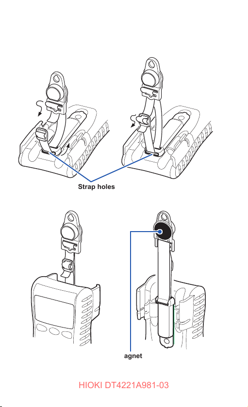
2.4 Installation in Measurement Location
Hanging the instrument with the strap
Attach the optional Z5004, Z5020 Magnetic Strap to the
instrument and attach the magnet to the wall surface (with metal
plate afxed).
DANGER
Those with medical electronics such as
pacemakers should not use the Z5004, Z5020
Magnetic Strap. Nor should such persons
approach the Z5004, Z5020. It is extremely
dangerous. The electronics may not operate
properly and the life of the operator may be put at
great risk.
CAUTION
• Do not use the Z5004, Z5020 in locations where it
may be exposed to rainwater, dust, or condensation.
In those conditions, the Z5004, Z5020 may be
decomposed or deteriorated. The magnet adhesion
may be diminished. In such case, the instrument
may not be hung in place and may fall.
• Do not bring the Z5004, Z5020 near magnetic media
such as oppy disks, magnetic cards, pre-paid
cards, or magnetized tickets. Doing so may corrupt
and may render them unusable. Furthermore, if the
Z5004, Z5020 is brought near precision electronic
equipment such as PCs, TV screens, or electronic
wrist watches, they may fail.
29
Installation in Measurement Location
HIOKI DT4221A981-03
Example: Z5004
Strap holes
Front Rear
30
Magnet
Attach it to the wall surface
(with metal plate afxed).
Performing Measurements
HIOKI DT4221A981-03
3
3.1 Inspection Before Use
Before using the instrument the rst time, verify that it operates
normally to ensure that no damage occurred during storage or
shipping. If you nd any damage, contact your authorized Hioki
distributor or reseller.
Appearance check of the instrument and test leads
Check item Action
The instrument is neither
damaged nor cracked.
The internal circuits are not
exposed.
The terminals are not
contaminated with debris.
The coating of the test leads is
neither broken nor frayed, or
the white portion or metal part
within the lead is exposed.
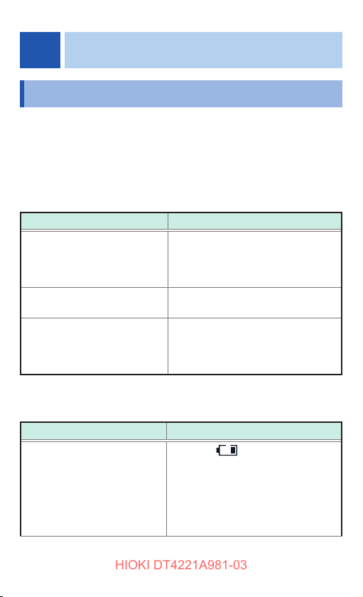
Check when turning on the power
(Set the rotary switch to any position other than OFF.)
Check item Action
The battery voltage is sufcient. When the
Visually check the instrument.
If it is damaged, there is a risk
of electric shock. Do not use the
instrument but send it for repair.
Remove contamination with a cotton
swab.
If the test lead is damaged, there is a
risk of electric shock. Do not use the
instrument but send it for repair.
indicator appears in
the top right corner of the display,
the battery voltage is low. Replace
the battery as soon as possible.
The power may be turned off when
the backlight lights up or a buzzer
sounds.
31
Inspection Before Use
5 6 7 8 9
5 6 7 8 9
HIOKI DT4221A981-03
Check item Action
No indicators are missing. Display all indicators and ensure that
no indicators are missing. (p. 54)
If any of the indicators are missing,
send the instrument for repair.
Operation check
This section introduces some of the operation checks. Periodical
calibration is necessary in order to ensure that this instrument
operates according to its specications.
Check that the test leads are not broken.
1
Check method Action
Regarding the continuity check,
deliberately short circuit the test
leads and then check the display.
For the DT4221
(The position of the rotary switch
varies depending on the model.)
Normal:
A buzzer sounds and the value
stabilizes at around 0
Abnormal:
A buzzer does not sound and
a numeric value other than the
above appears.
Corrective action:
The test leads may be broken.
Replace with those specied by
our company.
If the same phenomena persist
even after the test leads are
replaced, a malfunction may have
occurred. Halt inspection and then
send the instrument for repair.
.
Ω
32

Inspection Before Use
HIOKI DT4221A981-03
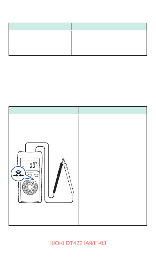
Measure samples (such as battery, commercial power
2
supply, and resistor) of which values have already been
known, and check that the appropriate values appear.
Check method Action
Example:
Perform the AC voltage
measurement to measure the
commercial power supply, and
then check the display.
Normal:
An already-known value appears.
(In this example, the commercial
voltage level should appear.)
Abnormal:
The measured value does not
appear.
A malfunction may have occurred.
Stop the inspection and do not
use the instrument.
33

Inspection Before Use
HIOKI DT4221A981-03
Check that the electric charge detection function
3
operates normally. (DT4221, DT4223)
Check method Action
Position the detector on a known
power supply, such as a power outlet.
Normal:
A buzzer sounds.
Abnormal:
A buzzer does not sound and
the display does not change.
Solution:
A malfunction may have
occurred. Stop the inspection
and do not use the instrument.
To check the electric charge properly, do not use the instrument
with test leads wrapped around the instrument. The detection
sensitivity of electric charge detection deteriorates.
Before measurements
WARNING
Observe the following to avoid short circuit accidents.
• Always verify the appropriate setting of the rotary
switch before connecting the test leads.
• Disconnect the test leads from the measurement
object before switching the rotary switch.
• Operate or connect the instrument by following
the procedure of each measurement example (or
procedure steps).
34

Measuring Voltage
HIOKI DT4221A981-03
3.2 Measuring Voltage
AC or DC voltage measurement and measurement using
the AC/DC automatic judgment (DT4221, DT4223) can be
performed.
Before measurements
WARNING
If the instrument is used in locations where the
rating indicated on the instrument or probes
is exceeded, the instrument may be damaged
resulting in personal injury. Do not use the
instrument in such locations. See “Measurement
categories” (p. 7).
The auto ranging function of this instrument automatically
selects the optimum measurement range. To change the range
arbitrarily, use the manual range. (p. 44)
Measuring AC voltage
Measure the AC voltage. The measured value is a true RMS. (p. Appx.1)
11
22
35

Measuring Voltage
3.1 の1
3.1 の 2, 3.2 交電
HIOKI DT4221A981-03
Measuring DC voltage
Measure the DC voltage.
11
22
Measurement using the AC/DC automatic judgment (DT4221, DT4223)
The AC or DC are automatically judged and the voltage is measured.
(The instrument does not measure both AC and DC at the same time.)
11
AC
voltage
voltage
DC
11
22
22
36

Measuring Frequencies
3.1 の動作確認1 4.4 相対値2 3.2 交流電圧
3.1 の 2
3.1 の 2, 3.2 交電
2.1, 3.2 直流電圧
HIOKI DT4221A981-03
3.3 Measuring Frequencies
The frequency can be checked. The frequency display is auto
ranging. The AC voltage range can be changed by pressing the
RANGE key.
• If signals out of the range of frequency measurement are measured,
“−−−−−” appears. Be aware of it.
• In a measurement environment with a large amount of noise, the
frequency may be displayed even with no input. This does not
indicate a malfunction of the instrument.
• The sensitivity of the frequency measurement is regulated by range.
(Minimum sensitivity voltage (p. 62))
When the value is less than the minimum sensitivity voltage, the
indicated value may uctuate. When the voltage range is lowered,
the value stabilizes. This does not apply to cases where the value
uctuates due to noise.
• During the measurement of low frequency voltage, if the auto range
does not stabilize and the frequency cannot be measured, x the
voltage range and measure again.
The frequency is measured.
11
22
37

Checking Continuity
3.2 交直自動判別 1
2.1, 3.2 直流電圧
HIOKI DT4221A981-03
3.4 Checking Continuity
The input short circuit is detected and informed via a buzzer.
WARNING
Before measuring, be sure to turn off the power to
the measurement circuit. Otherwise, electric shock
may occur or the instrument may be damaged.
11
Detection Threshold Buzzer
Short circuit detection 25 Ω±10
Open detection 245
38
22
For the DT4223
(The position of the rotary
switch varies depending on the
model.)
Sounds
Ω
(continuous buzzer sound)
Ω
±10
Does not sound
Ω

Measuring Diode (DT4222, DT4224)
HIOKI DT4221A981-03
3.5 Measuring Diode
(DT4222, DT4224)
The forward voltage of the diode is measured.
Forward voltage Buzzer Backlight
0.15 V to 1.5 V Intermittent sound
Less than 0.15 V Continuous sound Lights up in red (DT4224 only)
WARNING
Before measuring, be sure to turn off the power to
the measurement circuit. Otherwise, electric shock
may occur or the instrument may be damaged.
In the case of the opposite
AnodeCathode
connection
–
11
The open terminal voltage is approx. 2.5 V or less.
To avoid damage to the measurement object, check the
specications of the measurement object before use.
22
39

Measuring Resistance (DT4222, DT4223, DT4224)
3.1 の1
3.2 自動判別 2 3.3 周波数 3.4 導通 3.5 ダイオード
3.1 の 2, 3.2 交電
HIOKI DT4221A981-03
3.6 Measuring Resistance
(DT4222, DT4223, DT4224)
Resistance is measured.
To measure the low resistance accurately, it is necessary to
cancel the resistance of the test leads. Perform zero adjustment
for the displayed value using the relative value display (relative
function) in advance.
See: “Checking the relative value (REL)” (p. 50)
WARNING
Before measuring, be sure to turn off the power to
the measurement circuit. Otherwise, electric shock
may occur or the instrument may be damaged.
11
22
The open terminal voltage is approx. 2.0 V or less. The
measurement current (DC) varies depending on the range.
To avoid damage to the measurement object, check the
specications before use.
40

Measuring Capacitance (DT4222, DT4224)
3.1 の 2, 3.2 交電
2.1, 3.2 直流電圧
HIOKI DT4221A981-03
3.7 Measuring Capacitance
(DT4222, DT4224)
The capacity of the capacitor is measured.
WARNING
Before measuring, be sure to turn off the power to
the measurement circuit. Otherwise, electric shock
may occur or the instrument may be damaged.
Do not measure the capacitor which has been
charged.
11
When measuring the polar capacitor
• Connect the V terminal (red test lead) to the + terminal of
the capacitor and the COM terminal (black test lead) to the
− terminal.
• For components on a circuit board, measurement may not
be possible due to the effect of the peripheral circuit.
22
41

Checking the Electric Charge (DT4221, DT4223)
HIOKI DT4221A981-03
3.8 Checking the Electric Charge
(DT4221, DT4223)
Whether a power line is energized can be checked easily. If the
power line is energized, it is indicated via a buzzer and display.
Use this function for coated power lines. The detection may not
be made depending on the measurement conditions.
WARNING
To avoid electric shock, do not use the instrument
with test leads xed to the lead holders.
• To check the electric charge properly, do not use the instrument
with test leads wrapped around the instrument. The detection
sensitivity of electric charge detection deteriorates.
• Check that the detection function operates normally before
use. (p. 34)
Select the measurement
1
22
11
function.
Move the instrument
2
close to the power line.
When the detection level is
exceeded, a buzzer sounds.
42
Reference detection level
Reference detection level for the
power line
80 V AC to 600 V AC
Using Instrument Conveniently
3.1 の 2
3.2 交流・直流自動判別 1 3.2 交流・直流自動判別 2
HIOKI DT4221A981-03
4
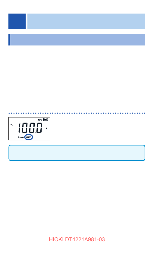
4.1 Selecting the Measurement Range
Auto or manual range can be selected. In the case of
measurement where the desired range can be selected,
[RANGE:] lights up at the bottom of the display.
• Auto range Sets the optimum range automatically in
• Manual range Sets the specic range manually.
Measuring with the auto range
When the measurement function is switched using the rotary
switch, the auto range is enabled.
accordance with the actual measurement.
(When the relative value (REL) function is enabled,
the range cannot be changed.)
[RANGE: AUTO] lights up.
43

Selecting the Measurement Range
3.2 交流・直流自動判別 1 3.2 交流・直流自動判別 2
3.2 交流・直流自動判別 1 3.2 交流・直流自動判別 2
HIOKI DT4221A981-03
Measuring with the manual range
DT4221, DT4222
Press .
[RANGE: MANUAL] lights up.
Each time
switched. When the key is pressed at the
highest range, the lowest range is specied
once again.
Example: When the range is 6.000 V to 600.0 V
To switch from the manual range to the auto range, press
for at least 1 second.
DT4223, DT4224
Press .
[RANGE: MANUAL] lights up.
is pressed, the range is
6 V → 60 V → 600 V → 6 V
44
Each time
switched. When the key is pressed at the
highest range, it returns to auto range.
Example: When the range is 6.000 V to 600.0 V
is pressed, the range is
6 V → 60 V → 600 V → auto range →
6 V
Retaining the Measured Value
HIOKI DT4221A981-03
4.2 Retaining the Measured Value
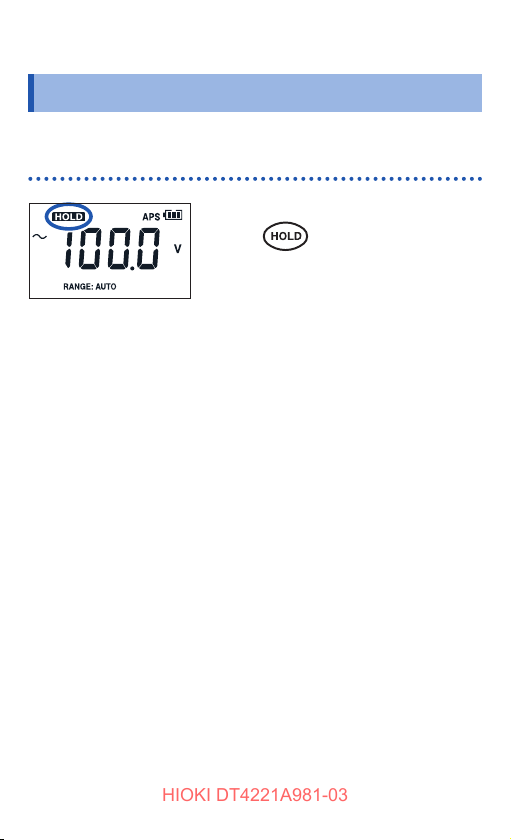
The measured value is retained. (The bar graph is updated.)
Retaining the measured value manually (HOLD)
To retain the measured value,
press
([HOLD] lights up and the measured
value is retained.)
To cancel the hold state, press it again.
([HOLD] goes off.)
.
45

Retaining the Measured Value
5 6 7 8 9
5 6 7 8 9
5 6 7 8 9
5 6 7 8 9
5 6 7 8 9
5 6 7 8 9
HIOKI DT4221A981-03
Automatically retaining the measured value when the value stablizes (AUTO HOLD) (DT4223, DT4224)
Press for at least 1 sec.
Blinks
(Waiting for
measured value to
stabilize)
Measured value stabilizes
Lights up
(Hold measurement value)
Re-connection
Lights up
(Waiting for measured
value to stabilize)
Press for at least 1 sec.
([HOLD] blinks, the instrument is
waiting for the measured value to
stabilize.)
When the measured value stabilizes,
a beeping sound is generated and
the value is retained.
([HOLD] lights up.)
When the test leads are moved
away from the measurement object,
reconnected again, and the measured
value stabilizes, a beeping sound is
generated and the new measured
value is retained.
When
[HOLD] is lit, the instrument returns
to the wait state. ([HOLD] blinks.)
Press
to cancel auto hold mode.
is pressed while
for at least 1 second
• If the input signal is too small for the relevant range, the
measured value cannot be automatically retained.
• The measured value is automatically retained after it
remains stable (for approx. 2 seconds) within the stable
range.
46

Conceptual diagram (AC voltage)
100.0 V
HIOKI DT4221A981-03
Retained
measured value
Auto hold
(Example) 100.0 V
Not retained automatically.
(The threshold is not exceeded.)
Retaining the Measured Value
99.0 V
Auto hold
(Example) 99.0 V
End
Threshold
(Example) 12.0 V
Measured
value
Start
End
Fluctuation range
Start
Measurement
Start
End
Conditions for auto holding
Measurement
Function*
AC voltage
DC voltage
(excluding the
Fluctuation range Threshold value
6.000 V/ 60.00 V/
600.0 V range: within
120 counts
6.000 V/ 60.00 V/
600.0 V range:
120 counts
600.0 mV range)
AUTO V within 120 counts 120 counts
Resistance,
within 100 counts 4900 counts
Continuity
Diode within 40 counts 1460 counts
* The auto hold function only operates for the listed measurement
functions.
47
Reducing the Noise (FILTER)
HIOKI DT4221A981-03
4.3 Reducing the Noise (FILTER)
WARNING
To avoid electric shock or other personal injury,
select the appropriate passband setting when
measuring the AC voltage. If an inappropriate
frequency is selected, the measured value
displayed will not be correct.
The inuence of high-frequency noise can be reduced with the
low pass lter (digital lter).
This function can be used when measuring the AC voltage and
the AC/DC automatic judgment.
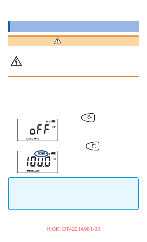
The passband setting for the low pass lter can be selected.
Example 1 (FILTER: OFF)
Press for at least 1
second.
(Current FILTER setting is displayed.)
Example 2 (FILTER: 100 Hz)
• When the desired passband setting is displayed for 2
seconds, the setting is applied and then the measurement
display reappears.
• If the FILTER setting is changed, the relative value function
(REL) will be canceled.
Each time
current FILTER setting is displayed, the
passband setting is changed.
[OFF] → [100 Hz] → [500 Hz] → [OFF]
is pressed while the
48

Reducing the Noise (FILTER)
0
20
40
60
80
100
120
140
0
20
40
60
80
100
120
140
10 100 1000 10000
HIOKI DT4221A981-03
Example of frequency property when a lter is used
Measured
value [V]
(AC voltage 600.0 V range, 100 V input)
Filter OFF
Passband 500 [Hz]
Passband 100 [Hz]
Frequency at 100 V input (Hz)
Example: Power frequency on an aircraft or marine vessel is
400 Hz
When voltage is 100 V
FILTER setting Displayed value
Normal
Abnormal 100 Hz Around 0 V
OFF
500 Hz
Approx. 100 V
49

Checking the Relative Value/Performing Zero Adjustment
3.1 の 2
4.1 オートレンジ 4.1 マニュアルレンジ 4.2 測定値をホールド 4.3 ノイズ軽減3.7 静電容量
HIOKI DT4221A981-03
4.4 Checking the Relative Value/
Performing Zero Adjustment
The relative value comparing to the standard value can be
checked (relative function).
It can also be used as the zero adjustment function.
Zero adjustment eliminates the inuences of the test lead wiring
resistance (continuity, resistance measurement) and the wiring
capacity (capacitor measurement).
• When the following measurement function is selected, this
function is disabled.
AUTO V, Frequency, Diode, Electric charge detection
• The DT4223 and DT4224 can display relative values for
frequency input.
Checking the relative value (REL)
Example 1: DC voltage measurement
For the DT4221, DT4222
When the standard value is measured,
press for at least 1 second.
For the DT4223, DT4224
When the standard value is measured,
press for at least 1 second.
50
[
] lights up.
The relative value is displayed.
To cancel the state, press it for at least 1
second again.
] goes off.)
([
Checking the Relative Value/Performing Zero Adjustment
3.2 交直自動判別 1
2.1, 3.2 直流電圧
HIOKI DT4221A981-03
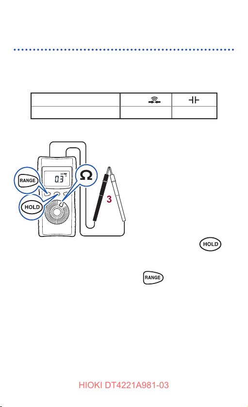
Performing zero adjustment
When performing zero adjustment, the condition of the test
leads varies depending on the measurement function.
Perform zero adjustment, referring to the table below.
Measurement function V, Ω,
Condition of the test leads Short circuit Open
22
11
33
Example 1:
Resistance measurement
(DT4222, DT4223, DT4224)
Select the measurement
1
function.
Connect the test leads
2
to the measurement
terminals.
Allow the test leads to
3
short circuit.
DT4222: Press
for at least 1 second.
DT4223, DT4224: Press
for at least 1
second.
(After zero adjustment: 0.0 Ω)
Measure the resistance.
4
51

Checking the Relative Value/Performing Zero Adjustment
HIOKI DT4221A981-03
Example 2:
22
11
33
Capacitor measurement
(DT4222, DT4224)
Select the measurement
1
function.
Connect the test leads
2
to the measurement
terminals.
Allow the test leads to
3
open.
52
DT4222: Press
for at least 1 second.
DT4224: Press for
at least 1 second.
(After zero adjustment: 0.000 µF)
Measure the capacitor.
4

Turning On the Backlight
HIOKI DT4221A981-03
4.5 Turning On the Backlight
The backlight can be turned on/off by pressing .
The backlight automatically turns off if the instrument is not
operated for 40 seconds.
The automatic backlight deactivation function can be disabled.
(p. 54)
4.6 Using the Auto Power Save (APS)
The auto power save function saves on battery consumption. If
the instrument has not been operated for 15 minutes, it enters
the sleep mode. When the sleep mode continues for approx. 45
minutes, the power turns off automatically.
In the default setting, the auto power save function is set to
enabled. (
It is also possible to disable the auto power save function.
At 30 seconds before the instrument enters the sleep mode,
the APS blinks to indicate its status. To continuously use the
instrument, press any key or turn the rotary switch.
Auto power save function
• When the instrument is in the sleep mode, press any key or
turn the rotary switch to recover from the sleep mode.
• If the instrument will be used for an extended period of
time, disable the auto power save function. (p. 54)
• After use, set the rotary switch to OFF. The sleep mode
consumes a small amount of current.
lights up.)
Recovering from a power shutdown
Set the rotary switch to OFF and turn on the power again.
53

Power-on Option Table
HIOKI DT4221A981-03
4.7 Power-on Option Table
The settings in the instrument can be changed or checked.
When the operation key is released after changing the setting,
the regular display then reappears.
+
Turn on the power while pressing the operation key.
(Turn the rotary switch from OFF.)
Setting
change
Method
(APS goes off.) (See p. 53)
Canceling
the auto
power save
function
(APS)
Disabling
the
automatic
backlight
deactivation
The APS and OFF displays are shown alternately.
When the power is turned off, the settings are disabled.
The backlight-auto and OFF displays are shown
alternately.
• When the power is turned off, the settings are disabled.
(DT4221, DT4222)
• The setting is retained even if the instrument is turned
off. To enable the setting again, repeat the same
action. (DT4223, DT4224)
54
(See p. 53)

Power-on Option Table
5 6 7 8 9
10
11
5 6 7 8 9
10
11
5 6 7 8 9
10
11
HIOKI DT4221A981-03
Setting
change
Checking
the
software
version
Check that there are no missing indicators. If any
Displaying
all
indicators
Displaying
the serial
number
indicator is missing, stop using the instrument and send
it for repair.
The 9-digit serial number is displayed 3 digits at a time.
Example: 123456789
Method
(First position from OFF)
Example: Ver 1.00
(Second position from OFF)
(Third position from OFF)
55

Power-on Option Table
HIOKI DT4221A981-03
56

Specications
HIOKI DT4221A981-03
5
5.1 General Specications
Power supply LR03 Alkaline battery × 1
Battery
indicator
warning voltage
Dimensions Approx. 72W × 149H × 38D mm (2.83″W × 5.87″H
Mass Approx. 190 g (6.7 oz.) (including the battery and
Operating
environment
Operating
temperature and
humidity
lights up.
•
• lights up.
• lights up.
• blinks.
• Power shutdown Less than 1.15 V*
*1: ±0.2 V (DT4221, DT4222)
*2: ±0.15 V (DT4223, DT4224)
× 1.50″D) (including the holster and rotary switch)
holster)
Indoors, pollution degree 2, altitude up to 2000 m
(6562 ft.)
• Temperature
−10°C to 50°C (14°F to 122°F) (DT4221, DT4222)
−10°C to 65°C (14°F to 149°F) (DT4223, DT4224)
• Humidity
−10°C to 40°C (14°F to 104°F): 80% RH or less
(no condensation)
40°C to 45°C (104°F to 113°F): 60% RH or less
(no condensation)
45°C to 65°C (113°F to 149°F): 50% RH or less
(no condensation)
1.4 V or more*
Less than 1.3 V to 1.4 V*
Less than 1.2 V to 1.3 V*
Less than 1.15 V to 1.3 V*
Less than 1.15 V to 1.2 V*
Less than 1.05 V to 1.15 V*
Less than 1.05 V*
1,*2
1,*2
1
2
1
2
1
2
57

General Specications
HIOKI DT4221A981-03
Storage
temperature and
humidity
Dust-proof and
water-proof
Drop-proof
distance
Product
warranty period
Accessories • DT4911 Test Lead
Options See: “Options (sold separately)” (p. 2)
Standards • Safety: EN61010
−30°C to 60°C (−22°F to 140°F) (DT4221, DT4222)
−30°C to 70°C (−22°F to 158°F) (DT4223, DT4224)
80% RH or less (no condensation)
IP42 (EN60529)
1 m on concrete (with the holster attached)
3 years (excluding the measurement accuracy)
• Holster (attached to the instrument, with a test
lead holder)
• Instruction Manual
• LR03 Alkaline battery × 1 (not installed in the
instrument)
• EMC: EN61326
58

Electrical Characteristics
HIOKI DT4221A981-03
5.2 Electrical Characteristics
Noise suppression
NMRR
Noise suppression
CMRR
Response time
(Auto range)
Display update
rate
Maximum rated
voltage between
terminals
• DCV: −60 dB or more (50 Hz/60 Hz)
• DCV: −100 dB or more
(DC/50 Hz/60 Hz, 1 k
unbalance)
Ω
• ACV: −60 dB or more
(DC/50 Hz/60 Hz, 1 k
unbalance)
Ω
• Power ON time: Within 2 seconds
(When the range does not move until the
measured value is displayed on the LCD screen)
• DCV: 0.7 to 0.8 seconds (0 V → 100 V auto
range operation)*
• ACV: 0.6 to 0.7 seconds (0 V → 100 V auto
range operation)*
•Ω: 1.0 to 1.1 seconds (Innity → 0 Ω auto
range operation)*
• Continuity: Open circuit or short circuit is
detected for at least 0.5 ms.*
Open circuit or short circuit is detected for at
least 600 ms.
*1,*
1
1
1
1,*3
4
• Measured value: 5 times/s (excluding
capacitance and frequency after the range is
2
xed)*
0.05 to 5 times/s (varies depending on the
capacitance)*
1 to 2 times/s (frequency)*
2
2
• Bar graph: Updated 40 times/s
6
600 V DC/AC or 3 × 10
V • Hz
59

Electrical Characteristics
HIOKI DT4221A981-03
Maximum rated
voltage between
measurement
600 V AC (Measurement category III)
300 V AC (Measurement category IV)
Anticipated transient overvoltage: 6000 V
terminals and
ground
Rated power
voltage
Maximum rated
power
1.5 V DC × 1
LR03 Alkaline battery × 1
250 mVA
(Power voltage 1.5 V, continuity measurement
input short-circuited, backlight lit) *
3
310 mVA
(Power voltage 1.5 V, diode measurement input
short-circuited, red backlight lit) *
4
Rated power • 36 mVA +20% or less
Power voltage 1.5 V, DCV measurement,
backlight off
• 6 mVA +20% or less
Power voltage 1.5 V, auto power save function
activated
Continuous
operating time
LR03 alkaline battery, DCV measurement
Backlight off: Approx. 40 hours*
Approx. 35 hours*
3
4
*1: Until the values stabilize within the accuracy specication range.
*2: Measured within the measurement range (excluding range movement).
*3: DT4221, DT4222
*4: DT4223, DT4224
60

Accuracy Table
HIOKI DT4221A981-03
5.3 Accuracy Table
Accuracy warranty period 1 year
Regulated power supply
range
Accuracy guarantee for
temperature and humidity
Temperature
characteristic
• rdg. (reading or displayed value): The value currently being measured
and displayed on the measuring instrument.
• dgt. (resolution): The smallest displayable unit, i.e., the input value that
causes the digital display to show a “1” as the least signicant digit.
AC voltage
1
Range
6.000 V ±1.0% rdg. ±3 dgt. ±2.5% rdg. ±3 dgt. 11.2 M
60.00 V ±1.0% rdg. ±3 dgt. ±2.0% rdg. ±3 dgt. 10.3 M
600.0 V ±1.0% rdg. ±3 dgt. ±2.0% rdg. ±3 dgt. 10.2 M
*1: The accuracy is specied in 1% or more of the range, however, ±5
dgt. should be added to 5% or less of the range.
• Overload protection: 660 V DC/660 V AC or 3 × 10
for 1 minute) (DT4221, DT4222)
40 to 500 Hz Over 500 Hz to 1 kHz
Until the power shutdown (1.15 V±0.2 V)
(DT4221, DT4222)
Until the power shutdown (1.05 V±0.15 V)
(DT4223, DT4224)
23°C±5°C (73°F±9°F), 80%RH or less
(no condensation)
• “Measurement accuracy × 0.1/°C” is
added (excluding 23°C±5°C (73°F±9°F)).
• For resistance 60.00 M
“Measurement accuracy × 0.4/°C” is
added (excluding 23°C±5°C (73°F±9°F)).
(only the DT4222)
Accuracy*
1
range,
Ω
Input impedance
Ω
100 pF or less
Ω
100 pF or less
Ω
100 pF or less
6
V • Hz (energized
±2.0%
±2.0%
±1.5%
61

Accuracy Table
HIOKI DT4221A981-03
6
• Overload protection: 750 V DC/750 V AC or 3 × 10
for 1 minute) (DT4223, DT4224)
• Transient overvoltage: 6000 V
• Crest factor: The crest factor is 3 up to 4000 counts and reduces
linearly to 2 at 6000 counts.
• Connection method: AC coupling
• Auto range movement threshold: More than 6,000 counts for upper
range, less than 540 counts for lower range
• Accuracy guarantee range for frequency: 40 Hz to 1 kHz (Measured values
outside the accuracy guarantee range for frequency are also displayed.)
• For 100 Hz with the lter ON, ±1.5% rdg. is added to the accuracy
specication between 40 Hz and 100 Hz and the accuracy is not
specied over 100 Hz.
• For 500 Hz with the lter ON, ±0.5% rdg. is added to the accuracy
specication between 40 Hz and 500 Hz and the accuracy is not
specied over 500 Hz.
Frequency
2
Range Accuracy
99.99 Hz ±0.1% rdg. ±2 dgt.
999.9 Hz ±0.1% rdg. ±2 dgt.
9.999 kHz ±0.1% rdg. ±2 dgt.
• Auto range movement threshold: More than 9999 counts for upper
range, less than 900 counts for lower range.
V • Hz (energized
Frequency minimum sensitivity voltage (sine wave)
Range
99.99 Hz
999.9 Hz
9.999 kHz
Measurement
range
5.00 Hz to
*1
99.99 Hz
100.0 Hz to
999.9 Hz
1.000 kHz to
9.999 kHz
6.000 V 60.00 V 600.0 V
0.600 V or
more
0.600 V or
more
0.600 V or
more
AC voltage range
6.00 V or more 60.0 V or more
6.00 V or more 60.0 V or more
6.00 V or more 60.0 V or more
62

Accuracy Table
HIOKI DT4221A981-03
*1: The measurement range from 5.00 Hz is only for the 6.000 V range.
The measurement range for other voltage ranges is 40.00 Hz to 99.99 Hz.
• The input is up to 3 × 10⁶ V • Hz.
• “−−−−” appears when no measurement can be made.
DC voltage
3
Range Accuracy Input impedance
600.0 mV ±0.5% rdg. ±5 dgt. 11.2 M
6.000 V ±0.5% rdg. ±5 dgt. 11.2 M
60.00 V ±0.5% rdg. ±5 dgt. 10.3 M
600.0 V ±0.5% rdg. ±5 dgt. 10.2 M
• Overload protection: 660 V DC/660 V AC or 3 × 10
for 1 minute) (DT4221, DT4222)
• Overload protection: 750 V DC/750 V AC or 3 × 10
for 1 minute) (DT4223, DT4224)
• Auto range movement threshold: More than 6000 counts for upper
range, less than 540 counts for lower range.
AUTO V
4
Range
600.0 V ±2.0% rdg. ±3 dgt. ±4.0% rdg. ±3 dgt. 900 k
*1: For AC voltage, the accuracy is specied in 1% or more of the range,
• Overload protection: 660 V DC/660 V AC or 3 × 10
for 1 minute) (DT4221, DT4222)
• Overload protection: 750 V DC/750 V AC or 3 × 10
for 1 minute) (DT4223, DT4224)
• Transient overvoltage: 6000 V
• Crest factor: The crest factor is 3 up to 4000 counts and reduces linearly to
2 at 6000 counts.
• Connection method: DC coupling
DC, 40 to 500 Hz Over 500 Hz to 1 kHz
however, ±5 dgt. should be added to 5% or less of the range.
Accuracy*
1
±2.0%
Ω
±2.0%
Ω
±2.0%
Ω
±1.5%
Ω
6
V • Hz (energized
6
V • Hz (energized
Input impedance
±20%
Ω
6
V • Hz (energized
6
V • Hz (energized
63

Accuracy Table
HIOKI DT4221A981-03
• Accuracy guarantee range for frequency: 40 Hz to 1 kHz (Measured
values outside the accuracy guarantee range for frequency are also
displayed.)
• For 100 Hz with the lter ON, ±1.5% rdg. is added to the accuracy
specication between 40 Hz and 100 Hz and the accuracy is not
specied over 100 Hz.
• For 500 Hz with the lter ON, ±0.5% rdg. is added to the accuracy
specication between 40 Hz and 500 Hz and the accuracy is not
specied over 500 Hz.
Continuity
5
Range Accuracy Measurement current
600.0
• Open circuit voltage: 1.8 V DC or less (DT4221, DT4222)
• Overload protection: 600 V DC/600 V AC or 3 × 10⁶ V • Hz (energized for 1 minute)
Current under overload: Steady state 15 mA or less, transient state 0.8 A or less
(DT4221, DT4222)
• Overload protection: 750 V DC/750 V AC or 3 × 10⁶ V • Hz (energized for 1 minute)
Current under overload: 1.5 mA or less
(DT4223, DT4224)
• Continuity ON threshold: 25
• Continuity OFF threshold: 245
• Accuracy guarantee condition: After zero adjustment has been performed
±1.0% rdg. ±5 dgt. 200 µA ±20%
Ω
2.0 V DC or less (DT4223, DT4224)
±10 Ω (continuous buzzer sound)
Ω
±10
Ω
Ω
64

Accuracy Table
HIOKI DT4221A981-03
Resistance
6
Range Accuracy Measurement current
600.0
6.000 k
60.00 k
600.0 k
6.000 M
60.00 M
• Open circuit voltage: 1.8 V DC or less (DT4222)
• Overload protection: 600 V DC/600 V AC or 3 × 10⁶ V • Hz (energized for 1 minute)
Current under overload: Steady state 15 mA or less, transient state 0.8 A or less
(DT4222)
• Overload protection: 750 V DC/750 V AC or 3 × 10⁶ V • Hz (energized for 1 minute)
Current under overload: 1.5 mA or less (DT4223, DT4224)
• Accuracy guarantee condition: After zero adjustment has been performed
• Auto range movement threshold:
More than 6000 counts for upper range.
Switches to the high impedance 60.00 M
are open, regardless of the range.
Less than 540 counts for lower range.
Capacitance
7
Range Accuracy Charging current
1.000 μF ±1.9% rdg. ±5 dgt. 10 n/100 n/1 μA ±20%
10.00 µF ±1.9% rdg. ±5 dgt. 100 n/1 μ/10 μA ±20%
100.0 µF ±1.9% rdg. ±5 dgt. 1 μ/10 μ/100 μA ±20%
1.000 mF ±1.9% rdg. ±5 dgt. 10 μ/100 μ/200 μA ±20%
10.00 mF ±5.0% rdg. ±20 dgt. 100 μ/200 μA ±20%
±0.9% rdg. ±5 dgt. 200 µA ±20%
Ω
±0.9% rdg. ±5 dgt. 100 µA ±20%
Ω
±0.9% rdg. ±5 dgt. 10 µA ±20%
Ω
±0.9% rdg. ±5 dgt. 1 µA ±20%
Ω
±0.9% rdg. ±5 dgt. 100 nA ±20%
Ω
±1.5% rdg. ±5 dgt. 10 nA ±20%
Ω
2.0 V DC or less (DT4223, DT4224)
range when the test leads
Ω
• Open circuit voltage: 1.8 V DC or less (DT4222)
2.0 V DC or less (DT4224)
65

Accuracy Table
HIOKI DT4221A981-03
• Overload protection: 600 V DC/600 V AC or 3 × 10⁶ V • Hz (energized for 1 minute)
Current under overload: Steady state 15 mA or less, transient state 0.8 A or less
(DT4222)
• Overload protection: 750 V DC/750 V AC or 3 × 10⁶ V • Hz (energized for 1 minute)
Current under overload: 1.5 mA or less (DT4224)
• Maximum count for each range: 1100 (1000 for 10.00 mF)
• Auto range movement threshold: More than 1100 counts for upper
range, less than 100 counts for lower range.
Switches to the high impedance 1.000 μF range when the test leads
are open, regardless of the range.
Diode
8
Range Accuracy
1.500 V ±0.9% rdg. ±5 dgt.
• Overload protection: 600 V DC/600 V AC or 3 × 10⁶ V • Hz (energized for 1 minute)
Current under overload: Steady state 15 mA or less, transient state 0.8 A or less
(DT4222)
• Overload protection: 750 V DC/750 V AC or 3 × 10⁶ V • Hz (energized for 1 minute)
Current under overload: 1.5 mA or less (DT4224)
• During the forward connection, an intermittent buzzer sounds (threshold:
0.15 V to 1.5 V).
• A continuous buzzer sounds at less than 0.15 V. (DT4222)
• A continuous buzzer sounds, red backlight lit at less than 0.15 V.
(DT4224)
Measurement
current
0.5 mA ±20%
(DT4221, DT4222)
0.2 mA±20%
(DT4223, DT4224)
Open circuit voltage
2.5 V DC or less
Voltage drop due to
battery consumption
Electric charge detection
9
Detection voltage range*
80 V AC to 600 V AC 50 Hz/60 Hz
*1: In contact with the insulated wire that is equivalent to IV2 mm
• During voltage detection, a continuous buzzer sounds.
1
Detection target frequency
66
2
.
Maintenance and Service
HIOKI DT4221A981-03
6
6.1 Repair, Inspection, and Cleaning
DANGER
Customers are not allowed to modify, disassemble,
or repair the instrument.
Doing so may cause re, electric shock, or injury.
Calibrations
IMPORTANT
Periodic calibration is necessary in order to ensure that the
instrument provides correct measurement results of the
specied accuracy.
The calibration frequency varies depending on the status of
the instrument or installation environment. We recommend that
the calibration frequency is determined in accordance with the
status of the instrument or installation environment and that you
request that calibration be performed periodically.
Cleaning
• To clean the instrument, wipe it gently with a soft cloth
moistened with water or mild detergent.
• Wipe the display gently with a soft, dry cloth.
IMPORTANT
Never use solvents such as benzene, alcohol, acetone, ether,
ketones, thinners or gasoline, as they can deform and discolor
the case.
Disposal
Handle and dispose of the instrument in accordance with local
regulations.
67

Troubleshooting
HIOKI DT4221A981-03
6.2 Troubleshooting
• When a malfunction of the instrument is suspected, check the
information in “Before sending the instrument for repair” and
then, if necessary, contact your authorized Hioki distributor or
reseller.
• When sending the instrument for repair, remove the battery
and pack it carefully to prevent damage during transportation.
Include cushioning material so the instrument cannot move
within the package. Be sure to include details of the problem.
Hioki cannot be responsible for damage that occurs during
transportation.
Before sending the instrument for repair
Question Solution
Can zero adjustment
be performed?
Can rechargeable
batteries be used?
Using the relative value display function, zero
adjustment can be performed. (p. 51)
Rechargeable batteries can be used.
However, the discharge characteristic of
these batteries is different from that of alkaline
batteries. Be aware that the remaining battery
power display does not function properly.
68

Symptom Check and/or corrective action
HIOKI DT4221A981-03
Nothing appears in
the display.
Or the display
disappears after a
short time.
The measurement
value does not
appear.
Even after the
measurement, 0
(zero) still appears.
Even after short
circuit of the probe,
the measured value
does not appear.
Zero adjustment is
not possible.
The display does
not stabilize and the
value uctuates; it is
difcult to read the
value.
Turning on the power
brings up the error
display.
When nothing is
connected, the error
display appears.
Check that the battey is not exhausted.
Replace with a new battery. (p. 24)
Check that the auto power save function has
not been activated.
Check the setting of the auto power save
function. (p. 53)
Check that the test lead is not broken.
Perform the continuity check to conrm the
continuity of the test leads. (p. 32)
If the test lead is broken, replace the lead.
Check that the test leads have been inserted
at the ends.
Check that the measurement method is
correct.
If no problems have been found, the
instrument may be malfunctioning. Send the
instrument for repair.
Check that the input signal is within the input
range for the instrument.
If there is any inuence from noise, use the
lter function of the instrument. (p. 48)
Reset the instrument. If the same symptom
still occurs even after resetting the instrument,
send the instrument for repair.
Troubleshooting
69

Error Display
HIOKI DT4221A981-03
6.3 Error Display
Error display Description Solution
Err 1
Err 2
Err 4
Err 5
ROM error
Program
ROM error
Adjustment data
EEPROM error
Memory data
ADC error
Hardware malfunction
When the error appears in
the display, it is necessary
to repair the instrument.
Contact your authorized
Hioki distributor or reseller.
70

Appendix
s
V(t)
V(t)
HIOKI DT4221A981-03
Appx. 1 RMS and Average
Difference between the RMS and Average
When converting AC to RMS, 2 methods are available, “True
RMS method (True RMS indication)” and “Average method
(Average rectifying RMS indication)”.
In the case of the sine wave where no skew is included, the same
values are indicated in both methods. However, if the waveform
is skewed, a difference occurs between the 2 methods.
The true RMS method is applied to this instrument.
The true RMS method determines RMS values of AC signals,
including harmonic components within the accuracy guarantee
frequency range, and display them.
In the average method, the input waveform is handled as a
sine wave where no skew is included (only single frequency).
The average of the AC signal is obtained, converted to the
RMS, and then displayed. If the waveform is skewed, a greater
measurement error occurs.
Measurement example True RMS Average rectifying
100 V sine wave 100 V 100 V
100 V square wave 100 V 111 V
Vavg Vrms
Vm
t
Vm: Maximum value, Vavg: Average value, Vrms: RMS, T: Time period
Sine wave
Vm=Vavg=Vrm
TT
Square wave
t
Appx.1

RMS and Average
HIOKI DT4221A981-03
Appx.2

HIOKI DT4221A981-03

HIOKI DT4221A981-03

HIOKI DT4221A981-03

www.hioki.com/
HIOKI DT4221A981-03
 Loading...