

Page 1

Instruction Manual
使用说明书
DT4211
DT4212
DIGITAL MULTIMETER
数字万用表
November 2013 Revised edition 1
2013年11月 修订一版
DT4211A981-01 13-11H
Page 2

Page 3

Contents
Introduction .........................................................................1
Verifying Package Contents ..............................................1
Options (sold separately) ..................................................2
Safety Notes ........................................................................4
Usage Notes ........................................................................8
1 Overview 15
1.1 Overview and Features .................................15
1.2 Parts Names and Functions .........................16
1.3 Display ...........................................................21
1
2
3
2 Preparation for Measurements 23
2.1 Measurement Workfl ow ................................23
2.2 Inserting/Replacing Batteries ......................24
2.3 Using Test Leads ...........................................26
3 Performing Measurements 29
3.1 Inspection Before Use ..................................29
3.2 Measuring Voltage.........................................33
Measuring AC voltage ...............................................33
Measuring DC voltage ..............................................34
3.3 Measuring Resistance ..................................35
3.4 Measuring Diode ...........................................36
3.5 Checking Continuity .....................................37
3.6 Measuring Electrostatic Capacities .............38
3.7 Measuring Frequencies ................................39
3.8 Measuring Duty Ratio ...................................40
3.9 Measuring Current ........................................41
Measuring DC/AC .....................................................41
4
5
6
7
Ind.Appx.
i
Page 4

Contents
3.10 Measuring Temperatures (DT4212)..............43
4 Using Instrument Conveniently 45
4.1 Selecting the Measurement Range ..............45
Measuring with the auto range .................................45
Measuring with the manual range .............................45
4.2 Retaining the Measured Value .....................46
Retaining the measured value (HOLD) .....................46
4.3 Checking the Relative Value/Performing
Zero Adjustment ............................................47
Checking the relative value (REL) ............................47
Performing zero adjustment ......................................48
4.4 Turning On the Backlight ..............................49
4.5 Using the Auto Power Save (APS) ...............49
5 Specifi cations 51
5.1 General Specifi cations .................................51
5.2 Electrical Characteristics .............................53
5.3 Accuracy Table ..............................................55
6 Maintenance and Service 63
6.1 Repair Inspection and Cleaning .................63
6.2 Troubleshooting ............................................64
6.3 Replacing Fuses ............................................67
Appendix Appx.1
Appx. 1 RMS and Average .............................Appx.1
ii
Page 5
Introduction
Introduction
Thank you for purchasing the HIOKI DT4211 (Average value
measurement model), DT4212 (True RMS measurement model)
Digital Multimeter.
To obtain maximum performance from the product, please read this
manual fi rst, and keep it handy for future reference.
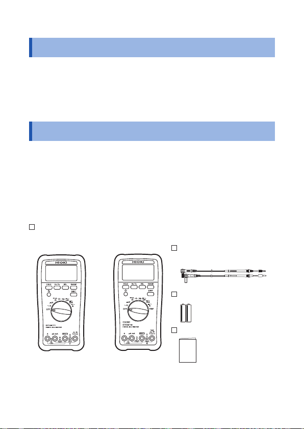
Verifying Package Contents
1
2
When you receive the instrument, inspect it carefully to ensure that
no damage occurred during shipping.
In particular, check the accessories, panel switches, and connectors.
If damage is evident, or if it fails to operate according to the
specifi cations, contact your authorized Hioki distributor or reseller.
Check the package contents as follows.
DT4211 (Average value measurement model) or DT4212 (True RMS
measurement model)
L9206 Test Lead
(p. 27)
R6P manganese battery × 2
DT4211
(Average value
measurement model)
The holster has been attached.
DT4212
(True RMS
measurement model)
Instruction Manual
1
3
4
5
6
7
Ind.Appx.
Page 6
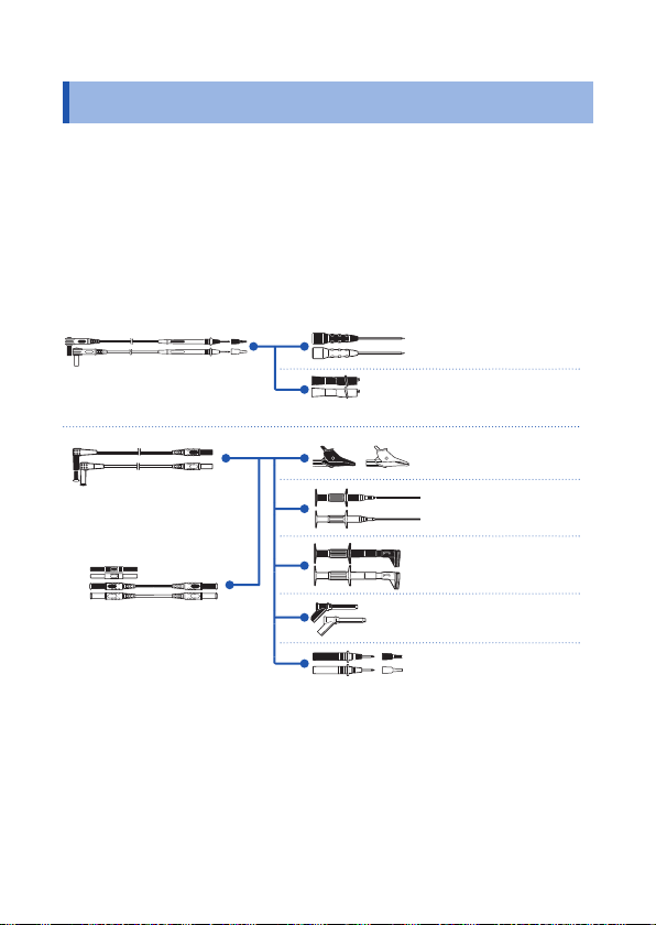
Options (sold separately)
Options (sold separately)
The following options are available for the instrument. Contact your
authorized Hioki distributor or reseller when ordering.
Connecting cables
*1: CAT IV 600 V/CAT III 1000 V/CAT II 1000 V
*2: CAT IV 600 V/CAT III 1000 V
*3: CAT III 1000 V *5: CAT III 300 V/CAT II 600 V
*4: CAT III 600 V *6: AC33 V /DC70 V
*1
L9206
Test Lead
*2
L4930
Connection Cable Set
(Length: 1.2 m)
*2
L4931
Extension Cable Set
(Length: 1.5 m, with the
coupling connector)
*6
L4933
Contact Pin Set
*5
L4934
Small Alligator Clip Set
*2
L4935
Alligator Clip Set
*3
9243
Grabber Clip
*4
L4936
Bus Bar Clip Set
*3
L4937
Magnetic Adapter Set
*1
L4932
Test Pin Set
2
Page 7
Options (sold separately)
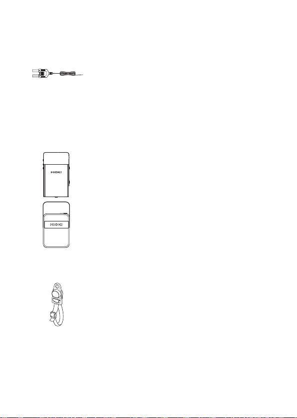
Temperature measurement (Only the DT4212 (True RMS
measurement model))
DT4910 Thermocouples (K) (p. 43)
• Temperature measuring junction: Exposed type (welding)
• Sensor length: Approx. 800 mm
Operating temperature: -40°C to 260°C (temperature
•
measuring part), -15°C to 55°C (connector)
Allowable tolerance: ±2.5°C
•
Carrying Case
C0201 Carrying Case
The instrument, test leads, instruction manual, and others
can be stored in the case.
C0202 Carrying Case
The instrument, test leads, instruction manual, and others
can be stored in the case.
Z5004 Magnetic Strap
Attach this strap to the instrument and secure it on the
For the detailed procedure of the C0201 Carrying Case and Z5004 Magnetic
Strap, refer to our Website.
wall surface such as a metal plate for use.
Handling the strap (p. 11)
1
2
3
4
5
6
7
Ind.Appx.
3
Page 8
Safety Notes
Safety Notes
This instrument is designed to conform to IEC 61010 Safety
Standards, and has been thoroughly tested for safety prior to
shipment. However, using the instrument in a way not described in
this manual may negate the provided safety features.
Before using the instrument, be certain to carefully read the
following safety notes.
DANGER
Mishandling during use could result in injury or death,
as well as damage to the instrument. Be certain that
you understand the instructions and precautions in
the manual before use.
WARNING
With regard to the electricity supply, there are risks
of electric shock, heat generation, fi re, and arc
discharge due to short circuits. If persons unfamiliar
with electricity measuring instruments are to use
the instrument, another person familiar with such
instruments must supervise operations.
Protective gear
WARNING
To avoid electric shock when measuring live lines,
wear appropriate protective gear, such as insulated
rubber gloves, boots and a safety helmet.
4
Page 9
Safety Notes
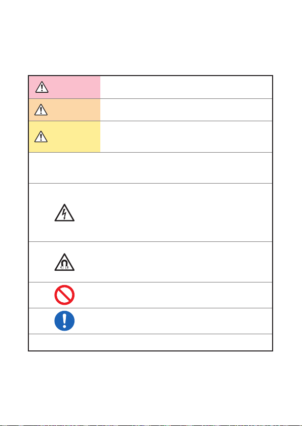
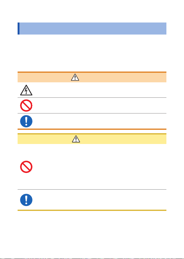
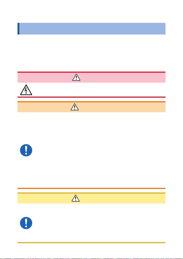
Notation
In this manual, the risk seriousness and the hazard levels are
classifi ed as follows.
DANGER
WARNING
CAUTION
IMPORTANT
Indicates an imminently hazardous situation that will
result in death or serious injury to the operator.
Indicates a potentially hazardous situation that may
result in death or serious injury to the operator.
Indicates a potentially hazardous situation that may
result in minor or moderate injury to the operator or
damage to the instrument or malfunction.
Indicates information related to the operation of the
instrument or maintenance tasks with which the
operators must be fully familiar.
Indicates a high voltage hazard.
If a particular safety check is not performed or the
instrument is mishandled, this may give rise to a
hazardous situation; the operator may receive an
electric shock, may get burnt or may even be fatally
injured.
Indicates a strong magnetic-fi eld hazard.
The effects of the magnetic force can cause
abnormal operation of heart pacemakers and/or
medical electronics.
1
2
3
4
5
6
Indicates prohibited actions.
7
*
Indicates the action which must be performed.
Additional information is presented below.
Ind.Appx.
5
Page 10
Safety Notes
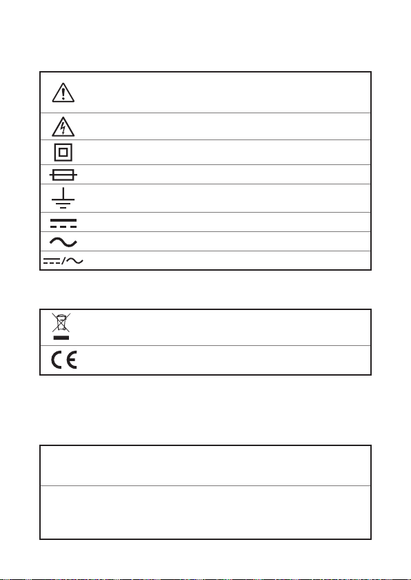
Symbols affi xed to the instrument
Indicates cautions and hazards. When the symbol is printed on
the instrument, refer to a corresponding topic in the Instruction
Manual.
Indicates that dangerous voltage may be present at this terminal.
Indicates a double-insulated device.
Indicates a fuse.
Indicates a grounding terminal.
Indicates DC (Direct Current).
Indicates AC (Alternating Current).
Indicates DC (Direct Current) or AC (Alternating Current).
Symbols for various standards
Indicates the Waste Electrical and Electronic Equipment
Directive (WEEE Directive) in EU member states.
Indicates that the instrument conforms to regulations set out by
the EC Directive.
Accuracy
We defi ne measurement tolerances in terms of rdg. (reading) and
dgt. (digit) values, with the following meanings:
(Reading or displayed value)
rdg.
The value currently being measured and indicated on the
measuring instrument.
(Resolution)
The smallest displayable unit on a digital measuring instrument,
dgt.
i.e., the input value that causes the digital display to show a “1”
as the least-signifi cant digit.
6
Page 11
Safety Notes
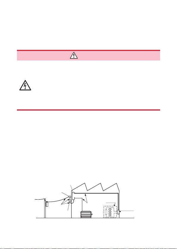
Measurement categories
To ensure safe operation of measuring instruments, IEC 61010
establishes safety standards for various electrical environments,
categorized as CAT II to CAT IV, and called measurement categories.
DANGER
• Using a measuring instrument in an environment
designated with a higher-numbered category than
that for which the instrument is rated could result in
This instrument conforms to the safety requirements for CAT II 1000 V, CAT III
600 V measuring instruments.
CAT II: When directly measuring the electrical outlet receptacles of
CAT III: When measuring the primary electrical circuits of heavy equipment
CAT IV: When measuring the circuit from the service drop to the service
See: “2.3 Using Test Leads” (p. 26)
a severe accident, and must be carefully avoided.
• Using a measuring instrument without categories in
an environment designated with the CAT II to CAT
IV category could result in a severe accident, and
must be carefully avoided.
the primary electrical circuits in equipment connected to an
AC electrical outlet by a power cord (portable tools, household
appliances, etc.)
(fi xed installations) connected directly to the distribution panel,
and feeders from the distribution panel to outlets
entrance, and to the power meter and primary overcurrent
protection device (distribution panel)
Distribution panel
Service entrance
Service drop
CAT IV
Power meter
Internal wiring
CAT III
Fixed installation
CAT II
T
Outlet
7
1
2
3
4
5
6
7
Ind.Appx.
Page 12
Usage Notes
Usage Notes
Follow these precautions to ensure safe operation and to obtain the
full benefi ts of the various functions.
DANGER
If the test lead or the instrument is damaged, there is
a risk of electric shock. Before using the instrument,
perform the following inspection.
• Before using the instrument, check that the coating of
the test leads are neither ripped nor torn and that no
metal parts are exposed. Using the instrument under
such conditions cou l d resu lt i n e lectrocuti on. Replace
the test leads with those specifi ed by our company.
• To avoid electric shock, check that the white or
red portion (insulated layer) within the cable is not
exposed. Do not use the cable if its internal colored
portion is exposed.
• Before using the instrument the fi rst time, veri fy that i t
operates normally to ensure that no damage occurred
during storage or shipping. If you fi nd any damage,
contact your authorized Hioki distributor or reseller.
8
Page 13
Usage Notes
Installation
Installing the instrument in inappropriate locations may cause a
malfunction of instrument or may give rise to an accident. Avoid the
following locations.
For details on the operating temperature and humidity, see the
specifi cations. (p. 51)
1
CAUTION
• Exposed to direct sunlight or high temperature
• Exposed to corrosive or combustible gases
• Exposed to water, oil, chemicals, or solvents
• Exposed to high humidity or condensation
• Exposed to a strong electromagnetic fi eld or electrostatic
Using the instrument with the stand
charge
• Exposed to high quantities of dust particles
• Near induction heating systems (such as high-frequency
induction heating systems and IH cooking equipment)
• Susceptible to vibration
• An unstable table or inclined surface
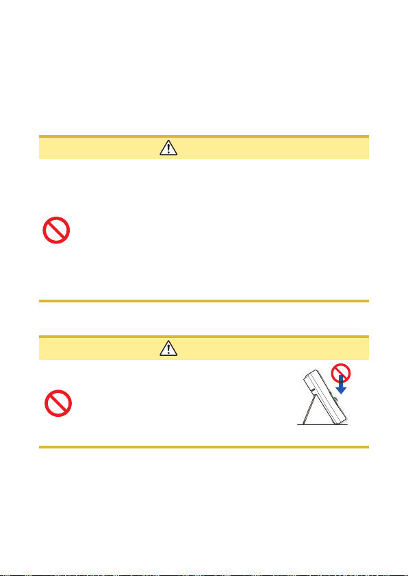
CAUTION
• Do not position the instrument on an
unstable table or inclined surface.
• When the instrument is set on the
stand, do not apply a strong force
above. Doing so may damage the
stand.
2
3
4
5
6
7
Ind.Appx.
9
Page 14
Usage Notes
Handling the cables
WARNING
To prevent electric shock, when measuring the
voltage of a power line use a test lead that satisfi es
the following criteria:
• Conforms to safety standards IEC61010 or EN61010
• Of measurement category II or III
• Its rated voltage is higher than the voltage to be
measured
All of the optional test leads for this instrument
conform to the safety standard EN61010. Use a test
lead in accordance with its defi ned measurement
category and rated voltage.
CAUTION
• Avoid stepping on or pinching the cable, which could
For the test leads supplied with the instrument or the options to be connected
to the instrument, see the following information.
Accessories and options
Test lead “2.3 Using Test Leads” (p. 26)
Thermocouples (K) “3.10 Measuring Temperatures (DT4212)”
damage the cable insulation.
• To avoid damaging the cables, do not bend or pull the
leads and the probe bases.
The ends of the test leads are sharp. Be careful to avoid
injury.
Reference
(p. 43)
10
Page 15
Handling the strap
Those with medical electronics such as pacemakers
should not use the Z5004 Magnetic Strap. Nor should
such persons approach the Z5004. It is extremely
dangerous. The electronics may not operate properly
and the life of the operator may be put at great risk.
• Do not use the Z5004 in locations where it may
be exposed to rainwater, dust, or condensation. In
those conditions, the Z5004 may be decomposed or
deteriorated. The magnet adhesion may be diminished.
In such case, the instrument may not be hung in place
and may fall.
• Do not bring the Z5004 near magnetic media such
as fl oppy disks, magnetic cards, pre-paid cards, or
magnetized tickets. Doing so may corrupt and may
render them unusable. Furthermore, if the Z5004 is
brought near precision electronic equipment such as
PCs, TV screens, or electronic wrist watches, they may
fail.
Usage Notes
DANGER
1
2
CAUTION
3
4
5
6
7
11
Ind.Appx.
Page 16
Usage Notes
Precautions during measurement
WARNING
If the instrument is used in locations where the rating
indicated on the instrument or probes is exceeded,
the instrument may be damaged resulting in personal
injury. Do not use the instrument in such locations.
See “Measurement categories” (p. 7).
• With regard to the 10 A range, the maximum input
current is 10 A DC/10 Arms AC. Supplying a current
in excess of the maximum input may damage the
instrument and result in personal injury. Do not
supply current in excess of the specifi ed limit.
Observe the following to avoid electric shock and/or
short circuits.
• Hazardous voltage may be generated in a free
measurement terminal. Do not touch the free
terminal.
• Use only test leads and optional equipment
specifi ed by our company.
• Do not allow the metal part of the test lead to touch
any exposed metal, or to short between 2 lines.
Never touch the metal end.
• When connecting the clip-type test lead to the
active terminal, do not allow the lead to touch any
exposed metal, or to short between 2 lines.
12
Page 17
CAUTION
• Do not input voltage or supply current exceeding the
specifi ed measurement range. Doing so may damage
the instrument.
• During the continuity chec k , diode test, or measureme nt
of resistance or electrostatic capacity, measurement
signals are generated in the terminals of the instrument.
Depending on the target for measurement, the
measurement signal may cause damage.
Seeing “Measurement current” and “Open circuit
voltage” in the accuracy table (p. 55), check, in advance,
that there are no adverse effects of the measurement
current and the open circuit voltage.
Usage Notes
1
2
3
Precautions during shipment
Observe the following during shipment. Hioki cannot be responsible
for damage that occurs during shipment.
CAUTION
• During shipment of the instrument, handle it carefully so
that it is not damaged due to a vibration or shock.
• To avoid damage to the instrument, remove the
If the instrument is not to be used for an extended
period of time
IMPORTANT
To avoid corrosion and/or damage to the instrument due to battery
leakage, remove the batteries from the instrument if it is to be
kept in storage for an extended period.
accessories and optional equipment from the instrument
before shipment.
13
4
5
6
7
Ind.Appx.
Page 18

Usage Notes
14
Page 19

Overview
1
1.1 Overview and Features
This instrument is a multi-function digital multimeter that performs
measurement functions for items such as voltage, current,
resistance, and capacity.
Main features and functions
• Large display on which the measured values can be read easily
• Environmental performance (can be used anywhere) (Operation
temperature: -10 to 50ºC (14°F to 122°F))
• Display hold (HOLD)
• Low power consumption for an extended time
Problem fi nding a suitable
installation location?
The strap with magnet allows the
For various purposes
The measurement test leads
and end pins can be selected.
instrument to be hung conveniently.
Large display of values
Backlighting to allow
users to read the
measurement values
in dark environments
15
Page 20
Parts Names and Functions
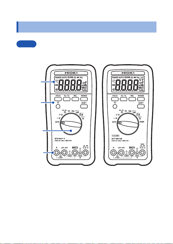
1.2 Parts Names and Functions
Front
Some indications are different between the DT4211 (Average value
measurement model) and DT4212 (True RMS measurement model)
Display
(p. 21)
Operation
keys (p. 17)
Rotary
switch
(p. 18)
Measurement
terminals
(p. 19)
DT4211
(Average value
measurement model)
DT4212
(True RMS
measurement model)
16
Page 21
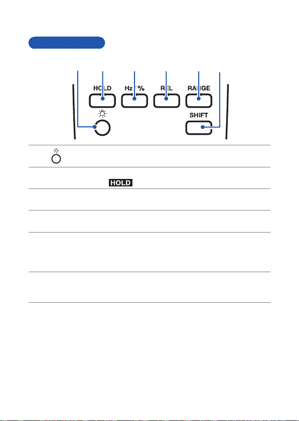
Operation keys
2
3
4
55 6
1
1
2
3
4
5
6
Parts Names and Functions
1
2
3
4
5
6
HOLD
Hz/%
REL
RANGE
SHIFT
2
1
3
4
Backlight key
Turns on/off the backlight. (p. 49)
Manually sets/cancels the hold function for the displayed
value. (
Switches the frequency (p. 39) and duty ratio (p. 40)
display.
Displays the relative value (REL). (p. 47) ([REL] lights up/
goes off.)
Sets the manual range and switches the range. (p. 45)
(Turns on/off the [RANGE:AUTO])
Cancels the manual range. (Pressed down for at least 1
second.)
Switches the function.
Cancels the auto power save function (APS). (Power-on
option)
lights up/goes off.) (p. 46)
6
17
Page 22
Parts Names and Functions
1
3
4
5
6
7
2
2
5
33 4
6
1
2
3
4
5
6
7
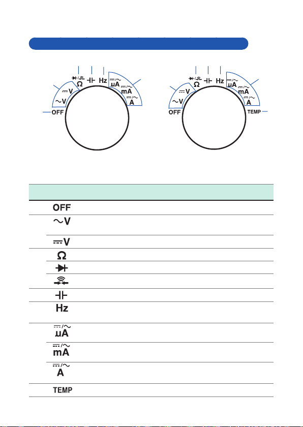
Rotary switches and measurement descriptions
3
4
5
6
2
2
5
4
6
1
measurement model)
1
2
3
4
5
6
7
DT4211
(Average value
Function
AC voltage and frequency
measurement
DC voltage measurement
Resistance measurement
Diode test
Continuity check
Electrostatic capacity
Frequency and duty ratio
measurement
DC (A) measurement/AC (A)
measurement
DC (mA) measurement/AC (mA)
measurement
DC (A) measurement/AC (A)
measurement
Temperature measurement -
DT4212
(True RMS
measurement model)
DT4211 DT4212
7
18
Page 23
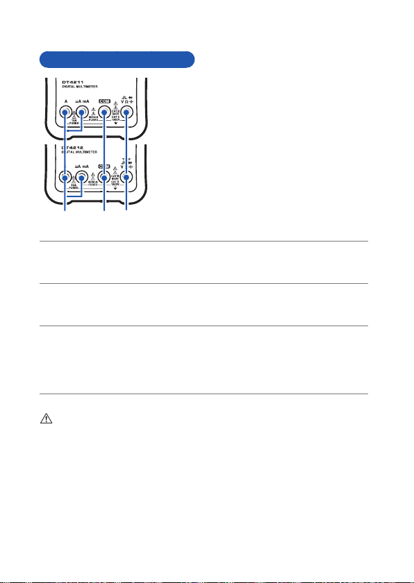
Measurement terminals
1
22 3
1
2
3
DT4211
(Average value measurement model)
Parts Names and Functions
DT4212
(True RMS measurement model)
3
1
Current measurement terminal.
1
Hereafter referred to as “A terminal (A terminal, mA terminal)”.
The red test lead is connected.
Commonly used for each measurement.
2
Hereafter referred to as “COM terminal”.
The black test lead is connected.
Used for voltage measurement, resistance measurement, continuity
3
check, diode test, temperature measurement, or electrostatic capacity
measurement.
Hereafter referred to as “V terminal”.
The red test lead is connected.
Be sure to carefully read the following precautions for the terminals with the
marking.
• “Precautions during shipment” (p. 13)
• “6.3 Replacing Fuses” (p. 67)
19
Page 24
Parts Names and Functions
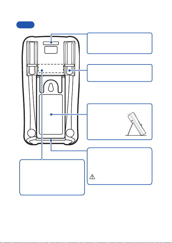
Rear
Serial number label
It is necessary for production
control such as product warranty.
Do not peel off the label.
Before checking the serial
number, remove the holster.
Strap hole
The optional Z5004 Magnetic
Strap can be attached.
Test lead holder
The test lead can be held.
Stand
The instrument
can be set on the
stand.
Battery cover
When replacing the batteries
(p. 24) or fuse (p. 67), remove the
cover.
See p. 24.
20
Page 25
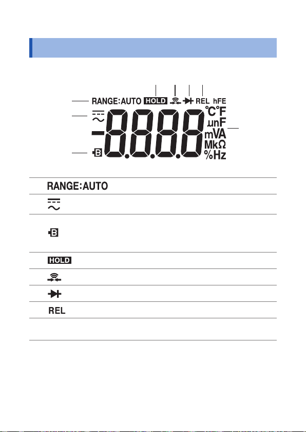
1.3 Display
1
2
3
4
5
6
7
8
1
2
3
4
Display
567
8
1
2
3
4
5
6
7
Each measurement
8
unit
Auto range (p. 45)
DC, AC
Battery warning indicator
Lights up when the battery voltage falls below
the voltage at which accuracy is guaranteed (2.4
V ± 0.15 V).
Retention of the measured value. (p. 46)
Continuity check (p. 37)
Diode (p. 36)
Relative value display (p. 47)
21
Page 26

Display
22
Page 27
2
3
1
Preparation for Measurements
2
2.1 Measurement Workfl ow
Before using the instrument, be sure to read “Usage Notes” (p. 8).
Installation and connection
Insert the batteries. (p. 24)
Perform the startup check. (p. 29)
Measurement
Turn on the power and select the
measurement function.
Attach the test leads to the
measurement terminals. (p. 26)
(As necessary, perform zero adjustment. (p. 48))
Connect the test leads to the
measurement object.
(As necessary)
Hold the display of the measured
value. (p. 46)
End of the measurement
As necessary, have other
optional items available and
ready.
1
Black
To ensure safe operation,
make sure to select a
measurement function and
then connect the test leads to
the measurement object.
3
Red
2
Move the test leads away from the measurement object and then turn off the power.
23
Page 28
Inserting/Replacing Batteries
2.2 Inserting/Replacing Batteries
Before using the instrument for the fi rst time, insert 2 R6P
manganese batteries or LR6 alkaline batteries. Before
measurements, check that the battery level is suffi cient. When the
battery charge is low, replace the batteries.
WARNING
To avoid el e ctri c s hock, disconnect the test leads from
the object to be measured before re p l ac ing the batteries.
To avoid the possibility of explosion, do not short
circuit, charge, disassemble, or incinerate batteries.
After battery replacement but before u sing the
instrument, reattach and screw down the battery cover.
CAUTION
Poor performance or damage from battery leakage
could result. Observe the cautions listed below.
• Do no mix new and old batteries, or different types of
batteries.
• Be careful to observe the battery polarity during installation.
• Do not use batteries after their recommended expiry date.
• Do not allow used batteries to remain in the instrument.
• To avo i d corrosion from b attery leakage an d /o r damage to
the instrument, remove the batteries from the instrument
if it is to be kept in storage for an extended peri od.
24
Page 29
Inserting/Replacing Batteries
• lights up when the batteries are exhausted. The accuracy is not
guaranteed. Replace the battery immediately.
• After use, be sure to turn off the instrument.
• Handle and dispose of batteries in accordance with local regulations.
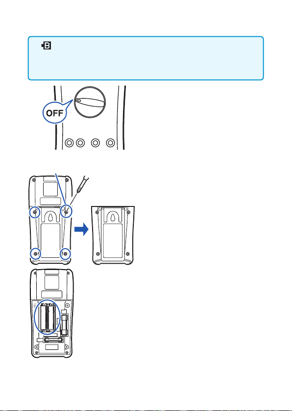
Have the following items
1
available and ready.
Screw
Rear
• Phillips screwdriver
• R6P manganese battery × 2
or LR6 alkaline battery × 2
Remove the test leads from
2
the instrument.
Set the rotary switch to OFF.
3
Remove the holster.
4
Using a Phillips screwdriver
5
remove the screws (4 locations)
from the battery cover on the
rear of the instrument.
Remove the battery cover.
6
Remove all of the old
7
batteries.
Insert 2 new batteries (R6P),
8
being careful to the battery
polarity.
Reattach the battery cover.
9
Secure the cover with the
10
screw.
Reattach the holster.
11
After the battery cover is removed,
the fuse can be seen. When
replacing the fuse, see “6.3
Replacing Fuses” (p. 67).
25
Page 30
Using T est Leads
2.3 Using Test Leads
The L9206 Test Leads supplied with the instrument are used for
measurements.
Depending on measurement locations, use our optional
measurement cables. For details on the optional items, see “Options
(sold separately)” (p. 2).
DANGER
To avoid electric shock, do not short circuit the line on
which voltage is applied at the tip of the test lead.
WARNING
•
To prevent a short circuit accident, be sure to use the test leads
with the sleeves attached when performing measurements in the
CAT III measurement category. (See “Measurement categories”
(p. 7))
• If the sleeves are inadvertently removed during measurement,
stop the measurement.
• When connecting the lead, use the correct voltage measurement
terminal (V terminal) and current measurement terminal (A
terminal). If an incorrectly connected lead is used, the instrument
may be damaged or short circuit accidents may occur.
• Use only test leads and optional equipment specifi ed by our
company.
26
CAUTION
• To ensure safe operation, use only test leads specifi ed
by our company.
• When carrying out measurements with the sleeves in
place, be careful to avoid damaging the sleeves.
• The tips of the metal pins are sharp and may cause
injury. Do not touch the tips.
Page 31

Using T est Leads
L9206 Test Lead
Black
Barriers
Sleeves
Plugs
Red
Cables Metal pins
Metal pin Connect to the object to be measured.
Sleeve Attach to the metal pins to prevent short circuit accidents.
Barrier Represents the safe handling distance from the metal pins.
Plug Connect to the measurement terminals on this instrument.
Cable Double sheathed cables (Length: approx. 980 mm, Diameter:
4 mm or less (sleeve attached)
19 mm or less (sleeve removed)
Diameter approx. 2 mm
During measurement, do not touch the area between
the barrier and the tip of the sleeve.
approx. 3.5 mm)
When the white portion inside the cable is exposed,
replace with a new L9206 Test Lead.
27
Page 32

Using T est Leads
1
2
Removing and attaching the sleeves
Removing the sleeves Attaching the sleeves
Gently hold the bottom of the
sleeves and pull the sleeves off.
Safely store the removed sleeves
so as not to lose them.
Insert the metal pins of the test
leads into the holes of the sleeves,
and fi rmly push them all the way
in.
Connecting to the instrument
Turn the rotary switch to the desired
1
measurement function.
Connect the test leads to the relevant
2
measurement terminals.
• Except the current measurement
1
COM terminal Connect the black test lead.
V terminal Connect the red test lead.
• Current measurement
2
COM terminal Connect the black test lead.
A/mA terminal Connect the red test lead.
A terminal
28
Page 33

Performing Measurements
3
3.1 Inspection Before Use
Before using the instrument the fi rst time, verify that it operates
normally to ensure that no damage occurred during storage or
shipping. If you fi nd any damage, contact your authorized Hioki
distributor or reseller.
Appearance check of the instrument and test leads
Check item Action
The instrument is neither
damaged nor cracked.
The internal circuits are not
exposed.
The terminals are not
contaminated with debris.
The coating of the test leads is
neither broken nor frayed, or
the white portion or metal part
within the lead is exposed.
Check when turning on the power
(Set the rotary switch to any position other than OFF.)
Check item Action
The battery voltage is suffi cient.
Visually check the instrument.
If it is damaged, there is a risk of electric
shock. Do not use the instrument but send
it for repair.
Remove contamination with a cotton
swab.
If the test lead is damaged, there is a
risk of electric shock. Do not use the
instrument but send it for repair.
When
the display, the battery voltage is low. The
accuracy is not guaranteed. Replace the
battery immediately.
appears at the left bottom of
29
Page 34

Inspection Before Use
Operation check
This section introduces some of the operation checks. Periodical
calibration is necessary in order to ensure that this instrument
operates according to its specifi cations.
Check that the test leads are not broken.
1
Check method Action
Regarding the continuity check,
deliberately short circuit the test
leads and then check the display.
Press
SHIFT
twice.
Normal:
A buzzer sounds and the value
stabilizes at around 0
.
Abnormal:
A buzzer does not sound and a
numeric value other than the above
appears.
Black
Corrective action:
The test leads may be broken.
Replace with those specifi ed by our
company.
If the same phenomena persist
even after the test leads are
Red
replaced, a malfunction may occur.
Halt inspection and then send the
instrument for repair.
30
Page 35

Inspection Before Use
Measure samples (such as battery, commercial power
2
supply, and resistor) of which values have already been
known, and check that the appropriate values appear.
Check method Action
Example:
Perform the AC voltage
measurement to measure the
commercial power supply, and then
check the display.
Red Black
Normal:
An already-known value appears.
(In this example, the commercial
voltage level should appear.)
Abnormal:
The measured value does not
appear.
The malfunction may occur.
Stop the inspection and do not use
the instrument.
31
Page 36

Inspection Before Use
Check that the fuse is not broken.
3
Check method Action
1. Remove the fuse from the
instrument. (p. 67)
2. Reattach the battery cover.
3. In the resistance measurement,
check the resistance of the
fuse. (Resistance measurement
(p. 35))
Before measurements
WARNING
Observe the following to avoid short circuit accidents.
• Always verify the appropriate setting of the rotary
switch before connecting the test leads.
• Disconnect the test leads from the measurement
object before switching the rotary switch.
• Operate or connect the instrument by following
the procedure of each measurement example (or
procedure steps).
Normal:
Fuse rating Resistance
630 mA Approx. 1.0
10 A Approx. 0.1
Abnormal:
If the value above is not obtained (the
value higher than that is displayed),
replace the fuse. (p. 67)
32
Page 37

Measuring Voltage
2
3
1
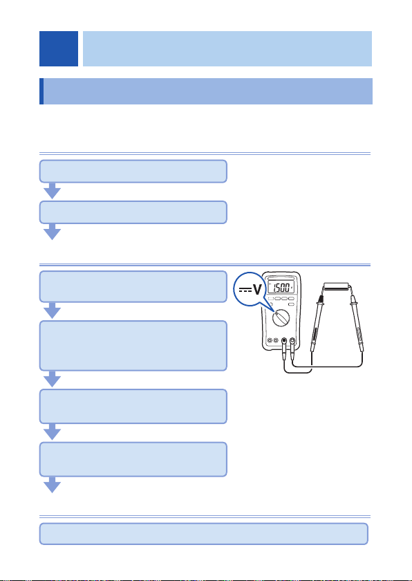
3.2 Measuring Voltage
The AC/DC voltage can be measured. Furthermore, the AC
frequency and duty ratio can be checked.
Before measurements
WARNING
If the instrument is used in locations where the rating
indicated on the instrument or probes is exceeded,
the instrument may be damaged resulting in personal
injury. Do not use the instrument in such locations.
See “Measurement categories” (p. 7).
The autoranging function of this instrument automatically selects the
optimum measurement range. To change the range arbitrarily, use
the manual range. (p. 45)
Measuring AC voltage
The AC voltage is measured.
1
Red Black
2
The measured value is an average
rectifying RMS indication (DT4211)
or true RMS indication (DT4212).
3
(p. Appx.1)
When the Hz/% key is pressed, the
frequency and duty ratio can be
measured. (p.
40)
33
Page 38

Measuring Voltage
2
3
Measuring DC voltage
3
Measure the DC voltage.
34
Black
Red
2
Page 39

3.3 Measuring Resistance
2
3
Resistance is measured.
WARNING
Before measuring, be sure to turn off the power to the
measurement circuit. Otherwise, electric shock may
occur or the instrument may be damaged.
1
3
Measuring Resistance
Black
The open terminal voltage is approx. 0.5 V or less. The
measurement current (DC) varies depending on the range.
To avoid damage to the measurement object, check the
specifi cations before use.
Red
2
35
Page 40

Measuring Diode
4
1
3
2
3.4 Measuring Diode
The forward voltage of the diode is measured.
If the forward voltage is within the range from 0 V to 1 V, the forward
voltage is displayed.
WARNING
Before measuring, be sure to turn off the power to the
measurement circuit. Otherwise, electric shock may
occur or the instrument may be damaged.
In the case of the opposite
Anode
1
Cathode
SHIFT
4
2
connection
Black
The open terminal voltage is approx. 3.0 V or less.
To avoid damage to the measurement object, check the
specifi cations of the measurement object before use.
Red
3
36
Page 41

Checking Continuity
3
4
2
3.5 Checking Continuity
The input short circuit is detected and informed via a buzzer.
WARNING
Before measuring, be sure to turn off the power to the
measurement circuit. Otherwise, electric shock may
occur or the instrument may be damaged.
1
4
SHIFT
Press
2
twice.
Black
Red
3
Detection Threshold Buzzer
Short circuit detection 90±40 or
A buzzer sounds during continuity
(short circuit detection), and the
resistance is displayed.
range fi xed)
(400
less
Sounds
(continuous
buzzer sound)
37
Page 42

Measuring Electrostatic Capacities
2
1
3
3.6 Measuring Electrostatic Capacities
The capacity of the capacitor is measured.
WARNING
Before measuring, be sure to turn off the power to the
measurement circuit. Otherwise, electric shock may
occur or the instrument may be damaged.
Do not measure the capacitor which has been
charged.
1
3
Black
• When measuring the polar capacitor
Connect the V terminal (red test lead) to the + terminal of
the capacitor and the COM terminal (black test lead) to the terminal.
• For components on a circuit board, measurement may not be
possible due to the effect of the peripheral circuit.
Red
2
38
Page 43

Measuring Frequencies
2
3
1
3.7 Measuring Frequencies
The frequency of the measured signal (square wave) is also
measured. The frequency display is auto-ranging.
1
3
Red
Black
When measuring frequencies of AC voltage and AC current
For the AC voltage measurement, use the ACV setting, and for the AC current
measurement, use the ACA, ACmA, or ACA setting. The frequency can
be checked by pressing the Hz/% key ([Hz] lights up). The voltage (current)
range is fi
•
If signals out of the range of frequency measurement are measured, the
display becomes unstable. Be aware of this point.
• The sensitivity of the frequency measurement is regulated by range.
(Minimum sensitivity voltage (p. 58)
When the value is less than the minimum sensitivity voltage (current),
the indicated value may fl uctuate. When the voltage (current) range is
lowered, the value stabilizes. This does not apply to cases where the
value fl uctuates due to noise.
• During the measurement of low frequency voltage (current), if the auto
range does not stabilize and the frequency cannot be measured, change
the voltage (current) range and measure again.
2
xed to the range before the Hz/% key is pressed.
39
Page 44

Measuring Duty Ratio
3
4
3.8 Measuring Duty Ratio
The duty ratio (or duty factor) indicates the ratio of the pulse width
and pulse repetition frequency. The instrument displays the ratio as
a percentage (%).
Duty ratio for the plus slope (D+): D+ = tw+/T ×100 (%)
2
Hz/%
0 V
+
tw
T
The duty ratio for the pulse is
1
measured.
4
t
Black
When measuring duty ratio of AC voltage and AC current
For the AC voltage measurement, use the ACV setting, and for the AC current
measurement, use the ACA, ACmA, or ACA setting. The duty ratio can be
checked by pressing the Hz/% key twice. The voltage (current) range is fi xed
to the range before the Hz/% key is pressed.
Red
3
40
Page 45

Measuring Current
3.9 Measuring Current
DC/AC is measured. DC and AC are switched with the SHIFT key.
DANGER
• Do not input any voltage to the current
measurement terminals.
Measuring DC/AC
Function
• A Selected to measure 4000 A DC/AC or less.
• mA Selected to measure 400.0 mA DC/AC or less.
• A Selected to measure 10 A DC/AC or less.
When measuring an unknown current
Set to the high range.
Doing so may result in short circuit accidents.
• To avoid electrical accidents, turn off the power to
the circuit before measuring and then connect the
test leads.
41
Page 46

Measuring Current
3
1
2
3
2
OFF
4
Measuring with the A range
1
Control board
3
2
Example: Measuring the current of the burner fl ame (A)
The measured current value of the burner fl ame varies with the
input impedance of the instrument.
The A input impedance of this instrument is approx. 100.
Measuring with the A range
1
OFF
3
42
SHIFT
/
TEMP
Red
Power
supply
Black
Black
2
Load
4
Red
Page 47

Measuring T emperatures (DT4212)
1
3
3.10 Measuring Temperatures (DT4212)
Using our optional DT4910 Thermocouples (K), temperatures can
be measured.
CAUTION
To avoid damage to the instrument, do not input any
voltage or supply current to the thermocouple.
Checking the temperature change
It can be checked in the relative
value display. (p. 47)
Black
1
3
2
Be careful to
observe the
polarity when
Red
connecting the
thermocouple.
DT4910
43
Page 48

Measuring T emperatures (DT4212)
When measuring temperatures with the thermocouple
applied to the surface of the measurement object
Clean the surface so that the thermocouple can make contact
with the object securely.
If temperature is not measured after the thermocouple is attached
The instrument or thermocouple may be malfunctioning.
Check this with the following procedure.
Short-circuit the V terminal of the instrument using the
test leads.
The ambient temperature
is displayed.
The ambient temperature
is not displayed.
The thermocouple may be
malfunctioning (blown).
Replace the thermocouple with a new
one.
The instrument is malfunctioning.
Send it for repair.
44
Page 49

Using Instrument Conveniently
4
4.1 Selecting the Measurement Range
Auto or Manual range can be selected.
• Auto range Sets the optimum range automatically in
• Manual range Sets the specifi c range manually.
Measuring with the auto range
When the measurement function is switched using the rotary
switch, the auto range is enabled.
Measuring with the manual range
accordance with the actual measurement.
[RANGE: AUTO] lights up.
Press the RANGE key.
[RANGE: MANUAL] lights up.
Each time the RANGE key is pressed, a
higher range is specifi ed. When the key is
pressed at the highest range, the lowest
range is specifi
Example: When the range is 400.0 mV to
400.0 mV 4.000 V 40.00 V 400.0 V
1000 V 400.0 mV
ed once again.
1000 V
To switch from the manual range to the auto range, press the
RANGE key for at least 1 second.
45
Page 50

Retaining the Measured Value
4.2 Retaining the Measured Value
When HOLD is pressed, the measured value is retained. (HOLD
lights up.)
Retaining the measured value (HOLD)
To retain the measured value, press
the HOLD key.
(HOLD lights up and the measurement
value is retained.)
To cancel the hold state, press it again.
(HOLD goes off.)
46
Page 51

Checking the Relative Value/Performing Zero Adjustment
4.3 Checking the Relative Value/ Performing Zero Adjustment
The relative value comparing to the standard value can be checked
(relative function).
It can also be used as the zero adjustment function.
Zero adjustment eliminates the infl uences of the test lead wiring
resistance (continuity, resistance measurement) and the wiring
capacity (capacitor measurement).
This function is disabled under the following conditions.
During OL display, frequency measurement, and duty measurement
Checking the relative value (REL)
Example: DC voltage measurement
When the standard value is
measured, press REL for at least 1
second.
( lights up.)
The relative value is displayed.
To cancel the display, press it again.
goes off.)
(
•
When the relative function is performed, the auto range is canceled.
(However, this excludes the capacity measurement function.)
• Do not input values exceeding 4000 counts for the DC voltage,
DC current, and temperature measurement (only the DT4212).
47
Page 52

Checking the Relative Value/Performing Zero Adjustment
1
2
3
4
3
2
4
Performing zero adjustment
When performing zero adjustment, the condition of the test leads
varies depending on the measurement function.
Perform zero adjustment, referring to the table below.
Measurement function
Condition of the test leads Short circuit Open
REL
1
2
Red
REL
4
3
Black
1
Black
Red
2
V,
, , A
4
Example 1: Resistance measurement
Select the measurement
1
function.
Connect the test leads to the
2
3
measurement terminals.
Allow the test leads to
3
short circuit.
Press the REL key.
4
(After zero adjustment: 0.0)
Measure the resistance.
5
Example 2: Capacitor measurement
Select the measurement
1
function.
Connect the test leads to
2
the measurement terminals.
Allow the test leads to
3
open.
Press the REL key.
4
(After zero adjustment: 0.00 nF)
Measure the capacitor.
5
48
Page 53

Turning On the Backlight
4.4 Turning On the Backlight
The backlight can be turned on/off by pressing the backlight key.
The backlight automatically turns off if the instrument is not operated
for approx. 80 seconds.
4.5 Using the Auto Power Save (APS)
The auto power save function saves on battery consumption. If the
instrument has not been operated for approx. 30 minutes, it enters
the sleep mode.
In the default setting, the auto power save function is set to enabled.
To continuously use the instrument, press any key or turn the rotary
switch.
Auto power save function
• When the instrument is in the sleep mode, press any key or
turn the rotary switch to recover from the sleep mode.
• If the instrument will be used for an extended period of time,
disable the auto power save function.
• After use, set the rotary switch to OFF. The sleep mode
consumes a small amount of current.
Canceling the auto power save function (APS)
While pressing the SHIFT key, turn the rotary switch.
49
Page 54

Using the Auto Power Save (APS)
50
Page 55

Specifi cations
5
5.1 General Specifi cations
Power supply
Battery indicator
warning voltage
Dimensions Approx. 91.6 W × 180.6H × 57.1 D mm (3.61 W ×
Mass Approx. 388 g (13.7 oz.) (including the batteries and
Operating
environment
Operating
temperature and
humidity
Storage temperature
and humidity
R6P manganese battery × 2 or
LR6 alkaline battery × 2
lights up when 2.4 V ± 0.15 V or less
7.11 H ×2.25 D) (including the holster)
holster)
Indoors, pollution degree 2, altitude up to 2000 m
(6562-ft.)
• Temperature
-10°C to 50°C (14°F to 122°F)
(However, 0°C to 50°C (32°F to 122°F) for the
temperature function)
• Humidity
0°C to 40°C (32°F to 104°F): 80% RH or less
(non-condensating)
40°C to 45°C (104°F to 113°F): 60% RH or less
(non-condensating)
45°C to 50°C (113°F to 122°F): 50% RH or less
(non-condensating)
Humidity (40M range)
•
0°C to 30°C (32°F to 86°F) : 80% RH or less
(non-condensating)
30°C to 40°C (86°F to 104°F) : 70% RH or less
(non-condensating)
40°C to 45°C (104°F to 113°F) : 60% RH or less
(non-condensating)
45°C to 50°C (113°F to 122°F) : 50% RH or less
(non-condensating)
-20°C to 60°C (-4°F to 140°F), 80% RH or less
(non-condensating)
51
Page 56

General Specifi cations
Dustproof and
waterproof
Product warranty
period
Accessories • L9206 Test Lead
Options See: “Options (sold separately)” (p. 2)
Replacement parts 630 mA/1000 V fuse for current terminal (A, mA)
Applicable
standards
IP40 (EN60529)
3 years (excluding the measurement accuracy)
• Holster (attached to the instrument, with a test
lead holder)
• Instruction Manual
• R6P manganese battery × 2 (not installed in the
instrument)
(Breaking capacity 50 kA Fast-blow type: 6.3 × 32
mm, SIBA)
10 A/1000 V fuse for current terminal (A)
(Breaking capacity 30 kA Fast-blow type: 10 × 38
mm, SIBA)
• Safety: EN61010
• EMC: EN61326
52
Page 57

Electrical Characteristics
5.2 Electrical Characteristics
Noise
suppression
NMRR
Noise
suppression
CMRR
Response time
(Auto range)
Display update
rate
Dielectric
strength
Maximum rated
voltage between
terminals
Maximum rated
current between
terminals
Maximum rated
voltage between
input terminals
and ground
• DCV: -45 dB or more (50 Hz/60 Hz)
• DCV: -100 dB or more (DC/50 Hz/60 Hz, 1k
unbalance)
• ACV: -60 dB or more (DC/50 Hz/60 Hz, 1k
unbalance) (However, -45 dB or more for the 1000 V
range)
• DCV: 1.2 to 1.4 seconds (0 V 100 V auto range
operation)
• ACV: 0.7 to 0.9 seconds (0 V 100 V auto range
operation)
: 1.2 to 1.4 seconds (Infi nity 0 auto range
•
operation)
Measured value:
3 times/s (after the range is fi xed, excluding the
resistance, continuity, electrostatic capacity, frequency)
2 times/s (resistance, continuity)
0.5 to 2 times/s (varies depending on the electrostatic
capacity)
5 times/s (frequency)
Between the measurement terminal and case
7.06 kV AC sine wave (50 Hz/60 Hz, 60 seconds)
V terminal: 1000 V DC/AC or 10
Current terminal (A): 10 A DC/10 A AC
Current terminal (A, mA) 400 mA DC/400 mA AC
1000 V AC (Measurement category II)
600 V AC (Measurement category III)
Anticipated transient overvoltage: 6000 V
6
V • Hz
53
Page 58

Electrical Characteristics
Rated power
voltage
Maximum rated
power
Rated power • 7.5 mVA +20% or less
Continuous
operating time
1.5 V DC × 2
R6P manganese battery × 2
LR6 alkaline battery × 2
100 mVA (max)
Power voltage 3.0 V, continuity measurement input
short-circuited, backlight lit
Power voltage 3.0 V, DCV measurement, backlight off
• 0.05 mVA +20% or less
Power voltage 3.0 V, auto power save function
activated
AA manganese batteries, DCV, backlight off
DT4211 (Average value measurement model):
Approx. 300 hours
DT4212 (True RMS measurement model):
Approx. 240 hours
AA alkaline batteries, DCV, backlight off
DT4211 (Average value measurement model):
Approx. 800 hours
DT4212 (True RMS measurement model):
Approx. 450 hours
54
Page 59

Accuracy T able
5.3 Accuracy Table
Accuracy warranty period 1 year
Regulated power supply range
Accuracy guarantee for
temperature and humidity
Temperature characteristic Adds “Measurement accuracy × 0.1/°C”
• rdg. (reading or displayed value): The value currently being measured and
displayed on the measuring instrument.
• dgt. (resolution): The smallest displayable unit, i.e., the input value that
causes the digital display to show a “1” as the least-signifi cant digit.
2.4 V ± 0.15 V or more (until lights
23°C ± 5°C (73°F ± 9°F), 80%RH or less
(non-condensating)
(excluding 23°C ± 5°C (73°F ± 9°F)).
AC voltage
1
*1
Range
*2
400.0 mV
4.000 V ±1.0% rdg. ±5 dgt.
40.00 V
400.0 V
1000 V
•
Overload protection: 1100 V DC/1100 V AC or 106 V • Hz (energized for 1 minute)
Transient overvoltage: 6000 V
• Crest factor (Only the DT4212 (True RMS measurement model)): The crest
factor is 2 up to 2800 counts and reduces linearly to 1.5 at 4000 counts.
*1: The accuracy is specifi ed in 1% or more of the range.
*2: Only the manual range.
±1.0% rdg. ±10 dgt.
±1.0% rdg. ±5 dgt.
Accuracy
40 to 500 Hz
Input impedance
11M ±2%
100 pF or less
+2%
10M
100 pF or less
up)
55
Page 60

Accuracy T able
DC voltage
2
Range Accuracy Input impedance
400.0 mV
4.000 V 11M ±2%
40.00 V
1000 V
• Overload protection: 1100 V DC/1100 V AC or 10
minute)
Resistance
3
Range Accuracy
400.0
4.000k
40.00k
400.0k
4.000M
40.00M ±1.5% rdg. ±3 dgt. Approx. 40 nA
• Overload protection: 1000 V DC/1000 V AC or 10
minute)
Current under short circuit: 300 A or less
Current under overload: Steady state 15 mA or less, transient state 0.8 A or
less
• Maximum capacity load: 10 mF
• Maximum inductive load: 10 H
±0.5% rdg. ±3 dgt.
±0.5% rdg. ±3 dgt. 10M
±0.5% rdg. ±3 dgt.
±0.5% rdg. ±2 dgt.
±0.5% rdg. ±2 dgt.
Over 100M
+2% 400.0 V
Measurement
current
Approx. 140 A
Approx. 40 A
Approx. 4 A
Approx. 400 nA
6
V • Hz (energized for 1
Open circuit
voltage
0.5 V DC or less
6
V • Hz (energized for 1
56
Page 61

Accuracy T able
Diode
4
Range Accuracy
1.000 V ±10.0% rdg. 0.5 mA
• Overload protection: 1000 V DC/1000 V AC or 10
minute)
Current under short circuit: 0.7 mA or less
Current under overload: Steady state 15 mA or less, transient state 0.8 A or
less
Continuity
5
Range Accuracy
400.0
• Overload protection: 1000 V DC/1000 V AC or 10
minute)
Current under short circuit: 300 A or less
Current under overload: Steady state 15 mA or less, transient state 0.8 A or
less
• Continuity ON threshold: 90 ± 40
• Response time: Open circuit or short circuit is detected for at least 0.5 ms.
±1.0% rdg. ±15 dgt. Approx. 140 A 0.5 V DC or less
Measurement
current
Measurement
current
or less (buzzer)
6
6
Open circuit
voltage
3.0 V DC or less
Voltage drop
due to battery
consumption
V • Hz (energized for 1
Open circuit
voltage
V • Hz (energized for 1
57
Page 62

Accuracy T able
Electrostatic capacity
6
Range Accuracy Charging current Open circuit voltage
50.00 nF ±1.5% rdg. ±15 dgt.
500.0 nF ±2.0% rdg. ±5 dgt.
5.000 F
±5.0% rdg. ±5 dgt. 50.00 F
100.0 F
• Overload protection: 1000 V DC/1000 V AC or 10
minute)
Current under short circuit: 50 A or less
Current under overload: Steady state 15 mA or less, transient state 0.8 A or
less
• Accuracy guarantee condition: After REL (zero adjustment) has been
performed
Approx. 30 A 1.5 V DC or less
6
V • Hz (energized for 1
Frequency
7
Minimum sensitivity
Range Accuracy
5.000 Hz
50.00 Hz
500.0 Hz
5.000 kHz
50.00 kHz
500.0 kHz
5.000 MHz ±0.1% rdg. ±3 dgt.
• Measurement range: 1 Hz or more
±0.1% rdg. ±3 dgt.
voltage
Square wave of 1.5 Vrms
or more
Square wave of 2.0 Vrms
or more
58
Page 63

Accuracy T able
DC (A)
8
Range Accuracy Input impedance
400.0 A
4000 A
• Overload protection: 630 mA/1000 V fuse, breaking capacity 50 kA
AC (A)
9
Range Accuracy
400.0 A
4000 A
• Overload protection: 630 mA/1000 V fuse, breaking capacity 50 kA
• Crest factor (only the DT4212 (True RMS measurement model)): The crest
factor is 2 up to 2800 counts and reduces linearly to 1.5 at 4000 counts.
*1: The accuracy is specifi ed in 1% or more of the range.
Accuracy guarantee range for frequency: 40 Hz to 500 Hz (Measured
values outside the accuracy guarantee range for frequency are also
displayed.)
±1.2% rdg. ±3 dgt. 100
*1
±1.2% rdg. ±5 dgt. 100
±5%
Input impedance
±5%
DC (mA)
10
Range Accuracy Input impedance
40.00 mA
400.0 mA
±1.2% rdg. ±3 dgt. 2 ±40%
• Overload protection: 630 mA/1000 V fuse, breaking capacity 50 kA
59
Page 64

Accuracy T able
AC (mA)
11
Range Accuracy
40.00 mA
400.0 mA
• Overload protection: 630 mA/1000 V fuse, breaking capacity 50 kA
• Crest factor (only the DT4212 (True RMS measurement model)): The crest
factor is 2 up to 2800 counts and reduces linearly to 1.5 at 4000 counts.
*1: The accuracy is specifi ed in 1% or more of the range.
Accuracy guarantee range for frequency: 40 Hz to 500 Hz (Measured
values outside the accuracy guarantee range for frequency are also
displayed.)
DC (A)
12
Range Accuracy Input impedance
4.000 A
10.00 A
• Overload protection: 10 A/1000 V fuse, breaking capacity 30 kA
AC (A)
13
Range Accuracy
4.000 A
10.00 A
±1.2% rdg. ±5 dgt. 2
±1.2% rdg. ±3 dgt. 0.05
±1.2% rdg. ±5 dgt. 0.05 ±40%
*1
*1
Input impedance
±40%
±40%
Input impedance
• Overload protection: 10 A/1000 V fuse, breaking capacity 30 kA
Crest factor (only the DT4212 (True RMS measurement model)): The crest
•
factor is 2 up to 2800 counts and reduces linearly to 1.5 at 4000 counts.
*1: The accuracy is specifi ed in 1% or more of the range.
Accuracy guarantee range for frequency: 40 Hz to 500 Hz (Measured
values outside the accuracy guarantee range for frequency are also
displayed.)
60
Page 65

Accuracy T able
Temperature
14
Thermocouple type Range Measurement range Accuracy
400.0°C -55.0°C to 0.0°C
K
700°C 400°C to 700°C
• Overload protection: 1000 V DC/1000 V AC or 10
minute)
Current under overload: Steady state 15 mA or less, transient state 0.8 A or
less
• The DT4910 Thermocouples (K) are used.
• The accuracy does not include the error of the DT4910 Thermocouples (K).
• Display update rate: 3 time/s
*1: In an environment where the temperature of the instrument is ±1°C and
stable, the accuracy is specifi ed.
Standard contact temperature compensation stability time: 120 minutes
(When the instrument environmental temperature changes quickly from
50°C to 23°C (122°F to 73°F ))
T = reading value (°F)
(-67°F to 32°F)
0.0°C to 50.0°C
(32°F to 122°F)
50.0°C to 400.0°C
(122°F to 752°F)
(752°F to 1292°F)
±2.0% rdg. ±2°C
(±(T-32)×0.02±3.6°F)
±2°C
(±3.6°F)
±2.0% rdg. ±1°C
(±(T-32)×0.02±1.8°F)
±2.0% rdg. ±1°C
(±(T-32)×0.02±1.8°F)
6
V • Hz (energized for 1
*1
61
Page 66

Accuracy T able
62
Page 67

Maintenance and Service
6
6.1 Repair, Inspection, and Cleaning
DANGER
Customers are not allowed to modify, disassemble, or
repair the instrument.
Doing so may cause fi re, electric shock, or injury.
Calibrations
IMPORTANT
Periodic calibration is necessary in order to ensure that the
instrument provides correct measurement results of the specifi ed
accuracy.
The calibration frequency varies depending on the status of the
instrument or installation environment. We recommend that the
calibration frequency is determined in accordance with the status of
the instrument or installation environment and that you request that
calibration be performed periodically.
Cleaning
• To clean the instrument, wipe it gently with a soft cloth moistened
with water or mild detergent.
• Wipe the display gently with a soft, dry cloth.
IMPORTANT
Never use solvents such as benzene, alcohol, acetone, ether,
ketones, thinners or gasoline, as they can deform and discolor the
case.
63
Page 68

Troubleshooting
Disposal
Handle and dispose of the instrument in accordance with local
regulations.
6.2 Troubleshooting
• When a malfunction of the instrument is suspected, check the
information in “Before sending the instrument for repair” and then,
if necessary, contact your authorized Hioki distributor or reseller.
• When sending the instrument for repair, remove the batteries and
pack it carefully to prevent damage during transportation.
Include cushioning material so the instrument cannot move within
the package. Be sure to include details of the problem.
Hioki cannot be responsible for damage that occurs during
transportation.
Before sending the instrument for repair
Symptom Check and/or remedy
Nothing appears in
the display.
Or the display
disappears after a
short time.
Check that the batteries are not exhausted.
Replace with new batteries. (p. 24)
Check that the auto power save function has not
been activated.
Check the setting of the auto power save function.
(p. 49)
64
Page 69

Symptom Check and/or remedy
The measurement
value does not
appear.
Even after the
measurement, 0
(zero) still appears.
Even after short
circuit of the probe,
the measured value
does not appear.
Zero adjustment is
not possible.
The display does not
stabilize and the value
fl uctuates; it is diffi cult
to read the value.
If the measured current value does not appear,
check that the fuse is not blown.
Check method: “Check that the fuse is not broken.”
(p. 32)
If the fuse is blown, replace it with the specifi ed
fuse. (p. 67)
If the measured current value does not appear,
check that the fuse holder is not deformed.
When removing the fuse, the holder is deformed
if excessive force is applied. Pinch it with needlenose pliers and restore the shape of the fuse
holder.
Check that the test lead is not broken.
Perform the continuity check to confi rm the
continuity of the test leads. (p. 30)
If the test lead is broken, replace the lead.
• Check that the test leads have been inserted at
the ends.
• Check that the measurement method is correct.
If no problems have been found, the instrument
may be malfunctioning. Send the instrument for
repair.
Check that the input signal is within the input range
for the instrument.
Troubleshooting
Other inquiries
Question Solution
Would like to perform
zero adjustment.
Using the relative value display function, zero
adjustment can be performed. (p. 48)
65
Page 70

Troubleshooting
Question Solution
Would like to replace
the fuse.
Would like to know
how to obtain the
fuse.
Can rechargeable
batteries be used?
The fuse can be purchased via authorized Hioki
distributor or reseller.
Rechargeable batteries can be used. However,
the discharge characteristic of these batteries is
different from that of alkaline batteries. Be aware
that the remaining battery power display does not
function properly.
66
Page 71

Replacing Fuses
6.3 Replacing Fuses
If a fuse is blown, replace it with a new one as follows.
For details on how to check that the fuse is blown, see “3 Check
that the fuse is not broken.” (p. 32).
WARNING
• To avoid electric shock, disconnect the test leads from
the object to be measured before replacing the fuse.
• Replace the fuse only with one of the specifi ed type,
characteristics, rated current, and rated voltage.
Specifi ed fuses
For A/mA terminal 630 mA/
For A terminal 10 A/
Do not use fuses other than those specifi ed
(especially, do not use a fuse with higher-rated
current) or do not short circuit and use the fuse
holder. Doing so may damage the instrument and
result in personal injury.
Rating Specifi cations
1000 V
1000 V
Manufacturer: SIBA
Meltdown characteristics: Fast-blow type
Breaking capacity: 50 kA
Size: 6.3 mm × 32 mm
Manufacturer: SIBA
Meltdown characteristics: Fast-blow type
Breaking capacity: 30 kA
Size: 10 mm × 38 mm
The fuses can be purchased via authorized Hioki distributor or reseller.
When removing the fuse, do not apply excessive force on the fuse
holder. If the fuse holder is deformed, the connection becomes
poor and the instrument cannot measure the current.
67
Page 72

Replacing Fuses
When replacing the fuse, do not allow foreign matter to
enter the instrument. It may cause a malfunction. Do not
remove the fuse using the tip of test lead L9206 supplied
with the instrument. The tip of the test lead may bend.
CAUTION
Remove the test leads
1
from the instrument.
Set the rotary switch to
2
OFF.
68
Screw
Remove the holster.
3
Using a Phillips
Rear
4
screwdriver, remove the
screws (4 locations) from
the battery cover.
Remove the battery cover.
5
Replace the fuse.
6
Reattach the battery cover.
7
Secure the cover with the
8
screw.
Reattach the holster.
9
Page 73

Appendix
Appx. 1 RMS and Average
Difference between the RMS and Average
When converting AC to RMS, 2 methods are available, “True RMS
method (True RMS indication)” and “Average method (Average
rectifying RMS indication)”.
In the case of the sine wave where no skew is included, the same
values are indicated in both methods. However, if the waveform is
skewed, a difference occurs between the 2 methods.
The DT4211 (Average value measurement model) uses the Average
method, and the DT4212 (True RMS measurement model) uses the
True RMS method.
In the true RMS method, the high frequency component is also
included and displayed.
In the average method, the input waveform is handled as a sine
wave where no skew is included (only single frequency). The
average of the AC signal is obtained, converted to the RMS, and
then displayed. If the waveform is skewed, a greater measurement
error occurs.
Appx.1
Page 74

RMS and Average
Measurement example True RMS Average rectifying
100 V sine wave 100 V 100 V
100 V square wave 100 V 111 V
V(t)
Vm
V(t)
Vm=Vavg=VrmsVavg Vrms
t
t
Sine wave
TT
Square wave
Vm: Maximum value, Vavg: Average value, Vrms: RMS, T: Time period
Appx.2
Page 75

13-09
Page 76

Page 77

DT4211
DT4212
数字万用表
使用说明书
2013年11月 修订一版 DT4211A981-01 13-11H
Chinese
Page 78

Page 79

附录
前言 ..............................................................................1
核对包装内容 .................................................................1
选件(另售) .................................................................2
安全注意事项 .................................................................4
使用注意事项 .................................................................8
1 概述 13
1.1 概述和特性 .................................................13
1.2
各部分的名称和功能 .................................... 14
1.3
显示 ..........................................................19
1
2
3
2 测量准备 21
2.1 测量流程 ....................................................21
2.2
安装/更换电池 ............................................22
2.3
使用测试线 .................................................24
3 执行测量 27
3.1 使用前的检查 .............................................27
3.2
测量电压 ....................................................31
测量交流电压 ......................................................31
测量直流电压 ......................................................32
3.3 测量电阻 ....................................................33
3.4
测量二极管 .................................................34
3.5
导通检查 ....................................................35
3.6
测量静电容量 .............................................36
3.7
测量频率 ....................................................37
3.8
测量占空比 .................................................38
3.9
测量电流 ....................................................39
测量直流/交流电流 ...............................................39
4
5
6
7
附录索引
i
Page 80

附录
3.10 测量温度(DT4212) ................................. 41
4 便利的使用方法 43
4.1 选择测量量程 .............................................43
用自动量程测量 ...................................................43
用手动量程测量 ...................................................43
4.2 保持测量值 .................................................44
保持测量值(HOLD) .........................................44
4.3 确认相对值/执行调零 ................................... 45
确认相对值(REL) ............................................45
执行调零 .............................................................46
4.4 打开背光灯 .................................................47
4.5
使用自动节电(APS) ...............................47
5 规格 49
5.1 一般规格 ....................................................49
5.2
电气特性 ....................................................51
5.3
精度表 .......................................................53
6 维护和检修 61
6.1 维修、检查和清洁 .......................................61
6.2
故障诊断 ....................................................62
6.3
更换熔断器 .................................................64
附录 附录1
附录1 有效值与平均值 ..................................附录1
ii
Page 81

前言
前言
感谢您购买 HIOKI DT4211(平均值测量型)、DT4212(真有效值
测量型)数字万用表。
要获得产品的最大性能,请首先阅读本手册,并保管在身边以备将来
查阅。
1
核对包装内容
当您收到本仪表时,请仔细检查,确保装运期间没有发生损伤。
尤其要检查附件、面板开关和连接器。如果损伤明显,或者不能按照
规格动作,请联系代理店或距您最近的营业所。
按照如下要求检查包装内容。
DT4211(平均值测量型)或 DT4212(真有效值测量型)
L9206 测试线
(p. 25)
5 号锰电池(R6P)× 2
DT4211
(平均值测量型)
皮套已安装。
DT4212
(真有效值测量型)
使用说明书
2
3
4
5
6
7
附录索引
1
Page 82

选件(另售)
选件(另售)
本仪表有以下一些选件可用,订货时,请联系代理店或距您最近的营
业所。
连接电缆
*1: CAT IV 600 V/CAT III 1000 V/CAT II 1000 V
*2: CAT IV 600 V/CAT III 1000 V
*3: CAT III 1000 V *5:CAT III 300 V/CAT II 600 V
*4: CAT III 600 V *6:AC33 V /DC70 V
*1
L9206
测试线
*2
L4930
连接线
(长 :1.2 m)
*2
L4931
延长线
(长 :1.5 m、带耦合连接
器)
*6
L4933
接触针
*5
L4934
小型鳄鱼夹
*2
L4935
鳄鱼夹
*3
9243
抓状夹
*4
L4936
测试夹
*3
L4937
磁铁接合器
*1
L4932
测试针
2
Page 83

温度测量(仅限 DT4212(真有效值测量型))
选件(另售)
携带盒
Z5004 带磁铁吊带
有关 C0201 携带盒及 Z5004带磁铁吊带的详细使用方法,请参考本公司网
页。
DT4910 K 型热电偶(p. 41)
• 测温连接点 :开槽式(焊接)
• 传感器长度 :约 800 mm
•
使用温度 :-40℃ 至 260℃(测温部位)、-15℃ 至 55℃(连
接器)
• 容差 :±2.5℃
C0201 携带盒
可将本仪表、测试线、使用说明书和其他东西装进盒里。
C0202 携带盒
可将本仪表、测试线、使用说明书和其他东西装进盒里。
将吊带系在本仪表上,并确保使用中吊带被牢牢固定在像
金属板那样的壁面上。
吊带的处理 (p. 10)
1
2
3
4
5
6
7
附录索引
3
Page 84

安全注意事项
安全注意事项
本仪表遵照 IEC61010 安全标准设计,且在装运前经过全面安全测
试。但是,用本手册没有记录的方法使用本仪器可能使提供的安全特
性失效。
使用本仪表前,务必仔细阅读以下安全注意事项。
危险
错误使用可能导致人身伤害或死亡,并损坏本仪表。使用
前,请您务必理解本手册中的使用说明和步骤。
警告
关于电源供应,电路短路有引发触电、发热、火灾和电弧
放电的风险。如果不熟悉电气测量仪表的人要使用本仪表,
必须由熟悉此类仪表的人指导操作。
保护用具
警告
测量火线时为避免触电,应穿戴绝缘橡胶手套、安全鞋和
安全头盔等合适的保护用具。
4
Page 85

记号
本手册将风险程度和危险级别分类如下。
安全注意事项
危险
警告
注意
重要
*
表示可能导致操作者死亡或重伤的紧迫危险状态。
表示可能导致操作者死亡或重伤的潜在危险状态。
表示可能导致操作者轻微或中度伤害或者导致本仪表
损坏或故障的潜在危险状态。
表示与本仪表操作或维护任务有关的信息,操作者必
须非常熟悉这些信息和内容。
表示高压危险。
如果不进行详细的安全检查或者本仪表被误用,可能
引发危险状态,操作者可能遭受电击,可能被烫伤或
者甚至可能遭受致命的人身伤害。
表示强磁场危险。
磁力的影响可能引起心脏起搏器或医用电子设备工作
不正常。
表示禁止行为。
表示必须被执行的行为。
更进一步的信息阐述如下。
1
2
3
4
5
6
7
附录索引
5
Page 86

安全注意事项
本仪表上的符号
表示注意和危险。当本仪表上显示有该符号时,查阅本操作手册
的相关主题。
表示该端子可能出现危险电压。
表示双重绝缘或强化绝缘所保护的设备。
表示熔断器。
表示接地端子。
表示直流(DC)。
表示交流(AC)。
表示直流(DC)或交流(AC)。
各种标准的符号
表示欧盟成员国关于废弃电子电气设备的指令(WEEE 指令)。
表示本仪表遵守 EC 指令规定的规则。
精度
我们用术语 rdg.(读取)和 dgt.(数字)值定义测量误差,其含义如
下:
(读取或显示数值)
rdg.
表示现在正在测量的值、测量仪表上正显示的值
(分辨率)
dgt.
数字测量仪表可显示的最小单位,即表示最小位的“1”。
6
Page 87

安全注意事项
T
测量分类
为确保测量仪表的安全操作,IEC61010 为被分类为 CAT II 至 CAT
IV 的各种电气环境建立安全标准,称其为测量分类。
危险
• 在指定使用较大编号分类的环境使用核准分类低于此的
测量仪表,可能导致严重的意外事故,此类行为必须被
本仪表符合 CAT II 1000V、CAT III 600V的安全要求。
CAT II: 当直接测量装置上的初级侧电路的插座,而该装置被电源线连接到
CAT III: 当直接测量被直接连接到配电盘上的重型装置(固定装置)的初级
CAT IV: 当测量使用入口至检修入口以及至电表和初级侧过电流保护设备的
严格避免。
• 在一个没有被指定为 CAT II 至 CAT IV 分类的环境使用
测量仪表,可能导致严重的意外事故,此类行为必须被
严格避免。
交流电插座上时(移动工具、家用电器等)
侧电路,并从配电盘到插座连接支线时
电路(配电盘)时
配电盘
检修入口
使用入口
CAT IV
电表
CAT III
固定装置
内部布线
CAT II
插座
1
2
3
4
5
6
7
参见 : “2.3 使用测试线”(p. 24)
附录索引
7
Page 88

使用注意事项
使用注意事项
以下这些预防措施确保安全操作,并获得各种功能的全部益处。
危险
如果测试线或者本仪表损坏,存在触电的风险。使用本仪
表前,执行以下检查。
• 使用本仪表前,检查测试线的被覆层既没有裂开也没有剥
落,并且没有金属部分暴露。在有损坏的状况下使用本仪
表可能会发生触电事故。请用我们公司指定的产品更换测
关于本仪表的安装
将本仪表安装在不合适的地方可能引起故障,或者可能引起意外事
故。请避免安装在以下场所。
有关使用温度和湿度的详情,参见规格。 (p. 49)
试线。
• 为避免触电,请检查并确保电缆内的白色或红色的部分
(绝缘层)未外露。若电缆内的彩色部分露出,请勿使用。
• 首次使用本仪表前,进行检查并确认其工作正常,以确认
保存或装运期间没有损伤。如果您发现任何损坏,请联系
代理店或距您最近的营业所。
注意
• 直接暴露在阳光或高温下
• 暴露在腐蚀性气体或易燃气体中
• 暴露在水、油、化学物质或溶剂中
• 暴露在高湿或结露的环境中
• 暴露在强电磁场或者静电环境中
• 暴露在有大量尘埃微粒的环境中
• 靠近感应加热系统(例如高频感应加热系统和 IH 烹饪装
置)
• 机械振动大的地方
• 不稳定的平台或者斜面
8
Page 89

用支架立起本仪表
使用注意事项
注意
• 不要将本仪表固定在不稳定的平台或
电缆的处理
者斜面上。
• 当本仪表用支架立起时,不要在其上
施加过大的力。这样做可能损坏支架。
警告
为防止触电,当测量电源线路的电压时,使用满足以下标
准的测试线 :
• 符合安全标准 IEC61010 或 EN61010
• 测量分类为 II 或 III
• 其额定电压大于要测量的电压
为本仪表准备的所有可选测试线均符合安全标准
EN61010。根据指定的测量分类和额定电压,使用合适的
测试线。
注意
• 避免踩踏或者挤压电缆,否则可能损伤电缆绝缘。
• 为避免损伤电缆,不要弯曲或拉扯引线和探头基座。
测试线前端尖锐,请小心使用以避免人身伤害。
有关本仪表附带的或者作为选件的测试线,参见以下信息。
附件和选件
测试线 “2.3 使用测试线”(p. 24)
K 型热电偶 “3.10 测量温度(DT4212)”(p. 41)
参考章节
1
2
3
4
5
6
7
附录索引
9
Page 90

使用注意事项
吊带的处理
身上有起搏器等医用电子设备的人请勿使用 Z5004 带磁铁
吊带 , 也请不要靠近 Z5004。此举极其危险,电子设备可
能工作不正常,并且操作者的生命可能被置于极大的风险
中。
• 在可能暴露于雨水、灰尘或者可能结露的地方,不要使
• 不要让 Z5004 靠近软盘、磁卡、充值卡或者磁性票据
危险
注意
用 Z5004。在这些环境中,Z5004 可能会腐蚀劣化。并
且,磁铁的磁性可能被削弱,本仪表可能会掉落。
等磁性媒介。这样做可能使这些东西出错或者不能使用。
此外,如果让 Z5004 靠近计算机、电视屏幕或者电子手
表等精密电子装置,可能会发生故障。
10
Page 91

测量期间的注意事项
使用注意事项
警告
如果在超过本仪表或探头额定参数的地方使用本仪表,本
仪表可能损坏,并导致人身伤害。请不要在那样的地方使
用本仪表。
参见 “测量分类”(p. 7)。
• 关于 10 A 量程,最大输入电流是 DC10 A/AC10 Arms。
超过此电流可能损坏本仪表,并导致人身伤害。请不要
输入超过指定上限的电流。
为避免触电或短路事故,请注意以下事项。
• 空闲输入端子可能发生危险电压。请不要触摸空闲端子。
• 只使用我们公司指定的测试线和选件。
• 不要用测试线的金属部分接触测量电路的 2 线之间。绝
对不要触摸金属部分。
• 当把夹型测试线连接到通电端子上时,请不要接触到2
线之间。
注意
• 请不要输入超过指定量程的电压或者电流。这样做可能
损坏本仪表。
• 在导通检查、二极管测试、电阻测量或者静电容量测量期
间,测量信号发生在本仪表的端子上。根据测量目的,测
量信号可能引起损坏。
参见精度表(p. 53)中的“测量电流”和“开路电压”,事
先检查有无测量电流和开路电压的不利影响。
1
2
3
4
5
6
7
附录索引
11
Page 92

使用注意事项
装运期间的预防措施
装运期间请注意以下事项。Hioki 不对装运期间发生的损坏负责。
注意
• 装运本仪表期间,小心操作,以免因振动或冲击被损坏。
• 为避免损坏,装运前从本仪表上拆下附件和选件。
如果本仪表长期不被使用
重要
如果本仪表将被长期保存,为避免电池漏液腐蚀或损坏本仪表,请
从本仪表上取出电池。
12
Page 93

1
概述
1.1 概述和特性
本仪表为多功能数字万用表,可测量电压、电流、电阻和电容等项
目。
主要特性和功能
• 大显示屏,易于读取测量值
• 环境性能(可在任何地方使用)(操作温度 :-10℃ 至 50℃)
• 显示保持(HOLD)
• 低功耗,可使用较长时间
您有找不到合适安装地点的
困扰吗?
带磁铁的吊带,可方便地悬挂设备。
根据用途
测量用的测试线和前端探针可
选。
大数值显示屏
带有背光灯,用户在昏
暗环境中也可读取测量
值
1
2
3
4
5
6
7
附录索引
13
Page 94

各部分的名称和功能
1.2 各部分的名称和功能
正面
DT4211(平均值测量型)和 DT4212(真有效值测量型)的一些标识
不同
显示屏
p. 19)
(
操作键
p. 15)
(
旋转开关
p. 16)
(
测量端子
p. 17)
(
14
DT4211
(平均值测量型)
DT4212
(真有效值测量型)
Page 95

操作键
2
3
4
55 6
1
1
2
3
4
5
6
各部分的名称和功能
2
1
3
4
1
HOLD
2
Hz/% 切换频率(p. 37)和占空比(p. 38)显示。
3
REL 显示相对值(REL)。(p. 45)([REL] 点亮 /熄灭。)
4
RANGE
5
SHIFT
6
背光键
打开 /关闭背光灯。(p. 47)
手动设置 / 取消保持数值显示功能。( 点亮 /熄灭。)
p. 44)
(
设置手动量程和切换量程。(p. 43)
(打开 / 关闭 [RANGE:AUTO])
取消手动量程。(按 1 秒以上。)
切换功能。
取消自动节电功能(APS)。(电源接通选项)
6
1
2
3
4
5
6
7
附录索引
15
Page 96

各部分的名称和功能
1
3
4
5
6
7
2
2
5
33 4
6
1
2
3
4
5
6
7
旋转开关和测量描述
3
4
5
6
2
2
5
4
6
1
1
2
3
4
5
6
7
DT4211
(平均值测量型)
测量功能
交流电压和频率测量 √ √
直流电压测量 √ √
电阻测量 √ √
二极管测试 √ √
导通检查 √ √
静电容量 √ √
频率和占空比测量
直流电流(μA)测量/ 交流电流(μA)
测量
直流电流(mA)测量 /交流电流(mA)
测量
直流电流(A)测量 / 交流电流(A)测量
温度测量 - √
DT4212
(真有效值测量型)
DT4211 DT4212
√ √
√ √
√ √
√ √
7
16
Page 97

测量端子
1
22 3
1
2
3
各部分的名称和功能
DT4211
(平均值测量型)
3
1
电流测量端子。
1
以下均表示为“A 端子(μA 端子、mA 端子)”。
连接红色测试线。
各种测量通用的端子。
2
以下均表示为“COM 端子”。
连接黑色测试线。
用于电压测量、电阻测量、导通检查、二极管测试、温度测量或静电
3
容量测量。
以下均表示为“V 端子”。
连接红色测试线。
务必仔细阅读以下关于带有 标记的端子的注意事项。
• “装运期间的预防措施”(p. 12)
• “6.3 更换熔断器”(p. 64)
DT4212
(真有效值测量型)
1
2
3
4
5
6
7
附录索引
17
Page 98

各部分的名称和功能
背面
吊带固定孔
可安装选件 Z5004 带磁铁吊带。
测试线支座
可固定测试线。
序列号标签
这是管理所必需的产品保证。
不要撕掉标签。
检查序列号之前,先拆下皮套。
18
支架
用支架立起。
电池盖板
当更换电池(p. 22)或熔断器
p. 64)时,拆下盖板。
(
参见 p. 22。
Page 99

1.3 显示
1
2
3
4
5
6
7
8
1
2
4
567
显示
1
8
2
3
1
2
3
4
5
6
7
各测量单位
8
自动量程(p. 43)
直流、交流
电池警告指示器
当电池电压低于可保证测量精度的电压时点亮
2.4 V ± 0.15 V)。
(
测量值保持。(p. 44)
导通检查(p. 35)
二极管(p. 34)
相对值显示(p. 45)
3
4
5
6
7
附录索引
19
Page 100

显示
20
 Loading...