

Page 1

Instruction Manual
DSM-8542
DIGITAL SUPER
MEGOHMMETER
July 2013 Revised edition 1 DS8542A981-01 13-07H
Page 2

Page 3

Preface
Thank you for purchasing the DSM-8542 and welcome to the growing family of HIOKI’s
Digital Supe r Megohm Meters/Current Mete rs.
The DSM-8542 is an insulation resistance meter up to 1000V in measuring voltage.
Incorrect operation of the meter potentially causes an electric shock or damage to a
sample. Please read this manual thoroughly before using the meter and exercise
reasonable caution regarding safety. Keep this manual handy for future reference.
The product has been shipped after minute preshipment inspection by HIOKI.
Nevertheless, please contact our distributor or sales office near your location in case of
a trouble.
I. Product Overview
The Digital Super Megohm Meter DSM-8542 is an insulation resistance meter
embedded with a high-sensitivity ammeter.
The meter has been developed to measure insulating materials of a high resistance
value, capable of measuring resistance within the range of 1 x 10
current within the range of 30fA to 10mA.
A liquid crystal display module (240 x 64 dots) of the meter allows easy viewing of
needed information and ease of use.
The meter is an insulation resistance meter and requires installation of an external
power supply unit as a power source for measurement. An external power supply unit
for measurement of insulation resistance is a customer supply scope. HIOKI E. E.
Corporation supplies a dedicated power supply unit PSU-8541 as an option. PSU-8541
incorporates a low-noise voltage source and is suitable for measuring insulation
resistance of insulating materials of large capacities.
Principal Features (When dedicated power supply unit PSU-8541 is used)
3
to 3 x 10¹⁶Ω and a
Measurable voltage range : 0.1 to 1000V
Measurable current range : 30fA to 10mA
Measurable resistance range : 1 x 10
3
to 3 x 10¹⁶Ω
Current limiter setting : 5mA, 10mA, 50mA (0.1 to 250V)
: 5mA, 10mA (251 to 1000V)
Integral time setting functi on : 2ms to 300ms
Trigger delay setting functi on : 0 to 9999ms
Automatic averaging measurement function
Voltage check function
Contact check function
Self-calibration function
Comparison decision, volume resistivity, surface resistivity computing
functions
i
Page 4

Data save and search functions
Histogram display function
Sequence programming function
Interlock function
GP-IB is a standard provision
Handler interface is a standard provision
RS-232 is a standard provision
II. About This Operational Manual
• Warning, Caution and Notice
Important safety precautions and operational instructions are described in this manual
under the following headings. Strictly follow these precautions and operational
instructions.
[Warning]
Indicates a potentially hazardous situation which could result in an electric
shock or equipment burning.
It is extremely important to strictly follow these instructions to prevent a
hazard.
[Caution]
Indicates a caution which could result in equipment damage.
Operate the meter exercising reasonable caution.
[Notice ]
Indicates an important item in operation.
ii
Page 5

III. Organizational Elements of Operational Manual
This operational manual has the following chapters. Please make certain to read the
manual carefully before operating the meter.
1. Preparations Before Operation
This chapter contains important information such as a check to be made during
uncrating, operating power supply and measuring cables.
2. Specification
The electrical specification of this meter is described.
3. Operating Principles
This chapter contains the operating principles, block diagram and other information.
4. Names and Functions of Components
This chapter describes the names and functions of keys and characters printed on
the front and rear panels.
5. Preparations for Measurement
This chapter describes the screen of the meter for measurement, settings on the
screen, operating method, methods for indicating measured values and other
matters.
6. Measurement
This chapter describes function settings of the meter, connection of measuring
terminals, and use of measuring jigs and measuring electrodes.
7. GP-IB Interface
This chapter describes control by the GP-IB interface.
8. RS-232 Interface
This chapter describes control by the RS-232 interface.
9. External Interfaces
This chapter describes the handler interface, external trigger input and interlock
input.
10. Maintenance
This chapter describes checks and calibration to be made for safe and reliable use
of this meter.
11. Product Full View
This chapter contains a full view of the product with dimensions.
iii
Page 6

IV. Safety Precautions
FOR SAFE USE OF THE METER
• Do the power supply voltage of the meter and commercial power supply voltage to be
supplied match? Please check it. Supplying 200V power supply voltage while the
power supply voltage of the meter is 100V sometimes causes damage to the meter.
• Be certain to ground the grounding terminal on the rear or the grounding rod of the
power cable to the ground.
V. Safety Alert Symbols
This symbol is marked where the operational manual
needs to be referred to.
This symbol indicates high voltage hazard and is
indicated on terminals where high voltage is output
such as meas uring t erminal s.
Indicated on the grounding terminal “GND” on the rear
of the meter. If the grounding pin of the power cable
cannot be grounded, be certain to ground this terminal.
!
Warning
symbol
Electrical
Grounding
terminal
VI. Operational Precautions
Please read this manual thoroughly before operating the meter to correctly handle it.
Strictly follow all the warning, caution and other messages contained in this manual to
prevent accidents and danger.
● Never operate the meter where a combustible gas exists. Otherwise an explosion or
a fire may break out.
● Be certain to ground the grounding pin of the power cable to prevent an accident. If
the grounding pin of the power cable cannot be grounded, be certain to ground the
grounding terminal located on the rear of the meter.
● High voltage up to 1000V is output between the measuring terminals on the panel of
this meter. Do not touch areas where a current is impressed during measurement to
prevent an electrical shock.
● Do not operate the meter in a dusty place or in a place subjected to vibration, direct
sunshine or steam. Otherwise a meter failure may result.
● Supply the power supply voltage specified in the operational manual. Otherwise a
fire or meter damage may result.
● Do not remove the cover of the meter.
Residual voltage sometimes still remains inside the meter after turning the power off
and it is dangerous to touch the inside of the meter. Please contact our sales office
near your location in case of a repair or internal adjustment.
● A cooling fan of a discharge type is installed inside the meter to prevent temperature
rises inside the meter. Poor ventilation of the fan causes meter failures. Provide a
space of more than 10cm behind the fan. Do not place anything on the ventilation
grills on one side and bottom of the meter.
iv
Page 7

Contents
1. Preparations Before Operation ····························································1
1.1 Check during Uncrating ····································································· 1
1.2 Operating Power Supply···································································· 1
1.3 Grounding ······················································································ 2
1.4 Measuring Cable·············································································· 2
1.5 Warming Up Time ············································································ 2
1.6 Memory Initializin g ··········································································· 2
2. Specification
2.1 Measurement Performance ································································3
2.1.1 DC current measurement ································································ 3
2.1.2 Resistance measurement ································································ 4
2.1.3 Measuring voltage output ································································ 4
2.2 Functional Specification····································································· 4
2.2.1 Measuring time setting···································································· 4
2.2.2 Voltage monitoring (Voltage check) ··················································· 4
2.2.3 Contact check function ···································································· 4
2.2.4 Self-calibration function and self-di agnosis function ······························ 5
2.2.5
Comparison measurement and deviation/percent measurement functions
··········· 5
2.2.6 Measurement (jig setting and da ta processi ng) f unction ························· 5
2.2.7 Measuring sequence program ·························································· 6
2.2.8 Storage and display functions of measured data··································· 6
2.2.9 Operability and display····································································6
2.2.10 Resume function·········································································· 6
2.2.11 Input and output functions (e xternal con trol i nterfaces) ························· 7
2.3 General Specifications ······································································8
2.4 Options·························································································· 8
2.4.1 Special options··················································································9
2.4.2 Common options················································································9
3. Operating Principles
3.1 Operating Principles ······································································· 10
3.2 Block Diagram of DSM-8542····························································· 11
4. Names and Functions of Components
4.1 Safety Alert Symbols······································································· 12
4.2 Front Panel··················································································· 13
4.3 Rear Panel ··················································································· 16
4.4 Command/Numeric Input Keys·························································· 17
4.5 Display Screen ·············································································· 20
a
Page 8

5. Preparations for Measurement
5.1 Connecting Meter and Power Supply Unit············································ 22
5.1.1 Connecting dedicated power supply unit PSU8541 ····························· 22
5.1.2 Connecting power supply other than dedicated power supply unit ·········· 22
5.2 Setting Measuring Conditions ··························································· 25
5.2.1 Screen types ·············································································· 27
5.2.2 Setting measuring mode································································ 33
5.2.3 Setting measuring voltage ····························································· 34
5.2.4 Setting current limiter ··································································· 35
5.2.5 Setting measuring range ······························································· 36
5.2.6 Setting integral time (sam pli ng tim e) ················································ 37
5.2.7 Setting averaging function ····························································· 38
5.2.8 Setting trigger mode····································································· 38
5.2.9 Creating a program ······································································ 39
5.2.10 Setting measured data buffer function ············································ 41
5.2.11 Setting operating environment ······················································ 43
5.2.12 Executing self-diagnostic function ([SETUP], SELF) ·························· 43
5.2.13 Self-calibration setting································································· 44
5.2.14 Setting measuring voltage source ([SETUP], POW R)························· 45
5.2.15 Setting high-speed measuring mode ([SETUP], FAST)······················· 47
5.2.16 Setting interface conditions ·························································· 47
5.3 Display and Processing of Measured Value ········································· 50
5.3.1 Displaying measured value ···························································· 50
5.3.2 Comparison measurement····························································· 51
5.3.3 Deviation display ········································································· 52
5.3.4 Creating histogram······································································· 53
6. Measurement
6.1 Functions of and Connecting Measuring Term inals································ 56
6.1.1 Functions of measuring terminals···················································· 56
6.1.2 Connecting measuring terminals ····················································· 57
6.2 Measuring Parts, Circuits and Other Items··········································· 57
6.2.1 Using measuring jigs ···································································· 57
6.2.2 Auto measurement······································································· 59
6.2.3 When measuring j ig is not used ······················································ 61
6.2.4 Measurement of circuits ································································ 62
6.3 Measuring Planar Sample ································································ 62
6.3.1 Measurement by pin terminal ························································· 62
6.3.2 Measurement by electrode for surface resist ance measurement ············ 63
6.3.3 Measurement by electrode for planar samp le····································· 63
6.3.4 Use of shielding box····································································· 65
6.4 Measuring Liquid Sample································································· 67
6.4.1 Measurement by electrode for liquid sampl e······································ 67
6.5 Current Measurement ····································································· 69
b
Page 9

6.6 Ending Measurement ······································································ 70
6.7 Measurement Check······································································· 70
6.7.1 Voltage check············································································· 70
6.7.2 Contact check············································································· 71
7. GP-IB Interface
7.1 Overview······················································································ 73
7.2 Specification ················································································· 73
7.3 Talker Function·············································································· 74
7.4 Response to Query Program Message ················································ 76
7.5 Listener Function ··········································································· 77
7.6 Device Clear Function····································································· 78
7.7 Device Trigger Function··································································· 78
7.8 Remote and Local Functions ···························································· 78
7.9 Program Messages········································································· 82
7.9.1 List of program messages······························································ 82
7.10 Precautions for Listener Specific ation ··············································· 95
7.10.1 Input buffer size········································································· 95
7.10.2 Input command message execute and message accept ····················· 95
7.10.3 Command parameter trouble ························································ 95
7.10.4 Limit on command message execute·············································· 95
7.10.5 Output buffer readout·································································· 95
7.11 Status Byte and Events·································································· 96
7.12 Status Data ················································································· 97
7.13 Status Byte Register ····································································· 98
7.14 Using Program Message·······························································100
7.15 Standard Event Status Register······················································103
7.16 Error Register·············································································105
7.17 Device Event Status Register·························································107
7.18 Initialization Value by *RST Message···············································109
8. RS-232 Interface
8.1 Overview·····················································································111
8.2 Connector Used and Signal Names···················································111
8.3 Changeover to GP-IB·····································································111
8.4 Connecting Control Signals and Flow Control······································111
8.5 Transmission Data Specification·······················································112
8.6 Reception Data Specification···························································113
8.7 Status Byte and Events ··································································113
9. External Interfaces
9.1 Handler Interface ··········································································114
9.1.1 Connector·················································································114
9.1.2 Signal functions ··········································································115
c
Page 10

9.1.3 Electrical characteristics of signal s ·················································117
9.2 External Trigger Terminal································································119
9.2.1 Connector·················································································119
9.2.2 Electrical characteristics ·······························································119
9.3 Interlock Terminal ·········································································120
9.3.1 Connector·················································································120
9.3.2 Electrical characteristics ·······························································120
9.4 Signal Timing ···············································································121
9.5 PSU-8541 Connectors····································································123
10. Maintenance
10.1 Periodical Checks for Maintenance ··················································124
10.2 Calibration ·················································································124
10.2.1 Equipment needed for calibration ·················································124
10.2.2 Calibration of measuring voltage ··················································124
10.2.3 Calibration of current meas urement ··············································124
10.3 Self-calibration Function································································125
10.4 Self-diagnosis Function·································································126
10.5 Service Organization of HIOKI························································127
10.6 Storage and Moving ·····································································127
11. Product Full View ········································································128
d
Page 11

1. Preparations Before Operation
1.1 Check during Uncrating
This product has been inspected carefully at the HIOKI factory in preshipment inspection.
Nevertheless, check the following items when uncrating the crate.
1) Any damage on the exteriors of the product.
2) Quantities of accessories
Check in accordance with Table 1.1 List of Accessories.
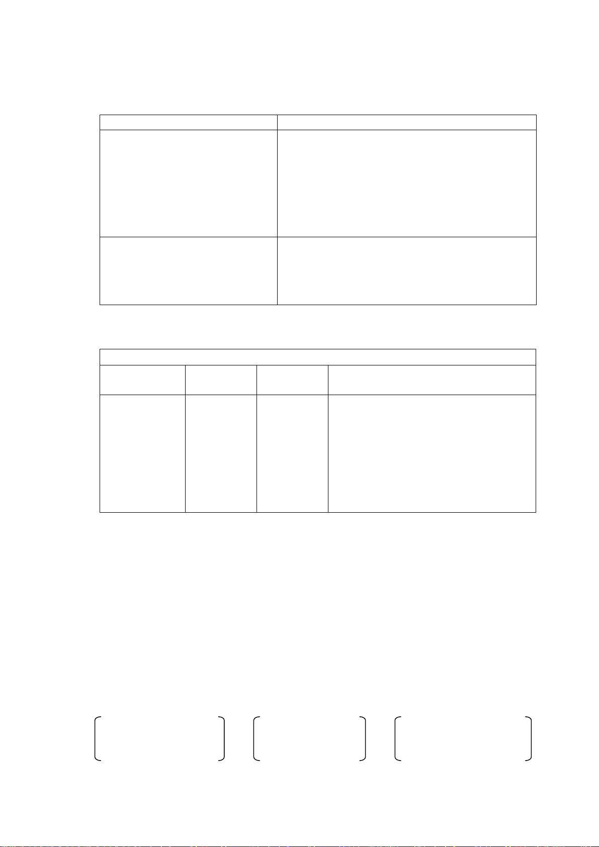
Table 1.1 List of Accessories
Item Quantity Remarks
Power cable 1 Power cable with three poles and grounding pin
3P-2P
conversion adapter
1 Changes the 3P plug of the power cable to a 2P plug
Operational manual 1 This manual
If any damage or missing accessory is found, please contact our distributor or sales
office near your location.
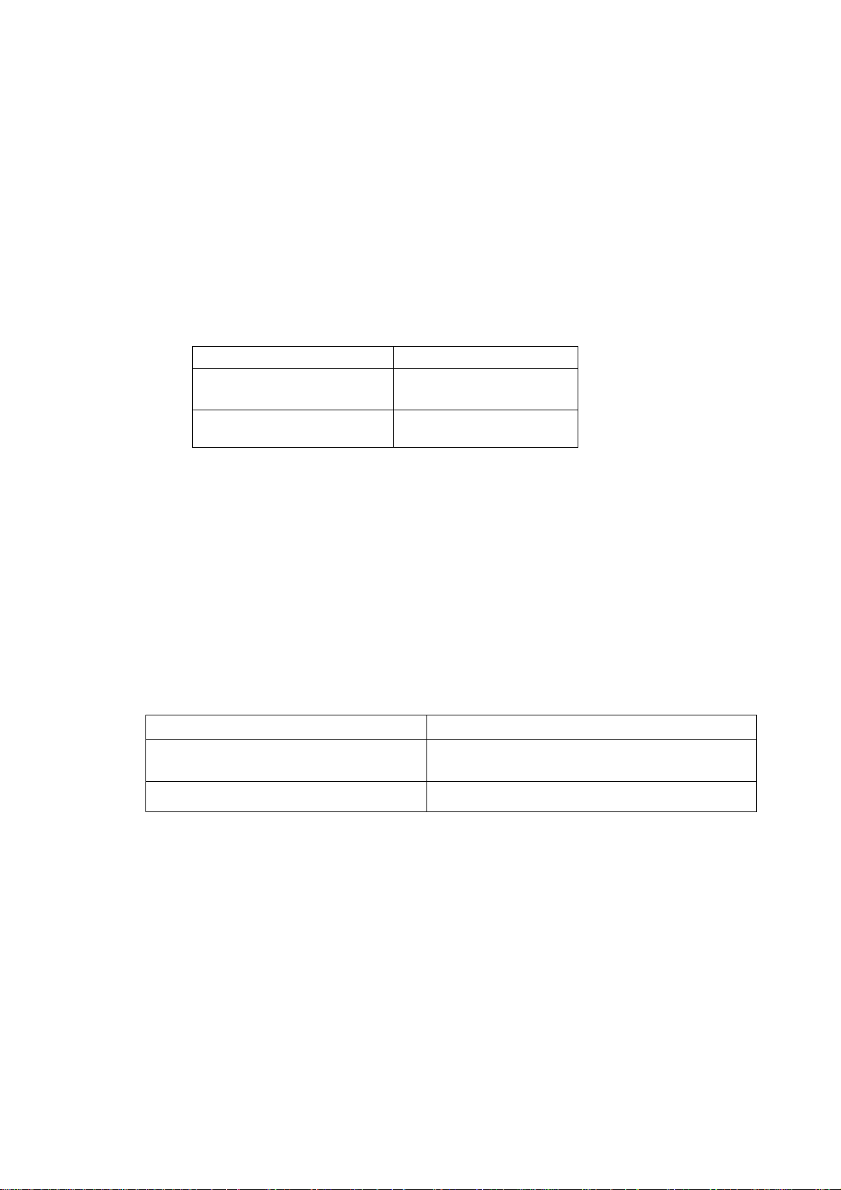
1.2 Operating Power Supply
This meter is powered by the following power supply.
Power supply voltage
100V ±10%
Change in power supply voltage Factory option other than 100V (115, 220 or 240V)
Dedicated power supply unit PSU8541 is rated to
100V only
Power supply frequency 50/60Hz
[Warning]
Before connecting the power plug, check that the AC power supply voltage to be used
matches the voltage specified on the rear panel.
If they do not match, a fire or damage to the meter may result.
[Caution]
Use a 3-conductor power cable conforming to the power supply voltage. A 100V
power cable is supplied wi th the meter as an accessory. Do not use this accessory
cable with other el ectric equipme nt.
1
Page 12

1.3 Grounding
Be certain to ground the grounding terminal located on the rear of the meter or the
grounding pin of the power cable to prevent an accident such as an electrical shock.
The round pin of the 3P plug attached to the power cable is the grounding pin. Plug the
cable to a plug socket that has a grounding device.
When using the 3P- 2P conver sion adapter, be certain to ground the grounding lead wire
from the adapter or the grounding terminal located on the rear of the meter.
[Warning]
Be certain to ground the grounding pin of the power cable to prevent an accident.
If the grounding pin of the power cable cannot be grounded, be certain to ground the
grounding terminal located on the rear of the meter.
1.4 Measuring Cable
1) Low-noise cable
This meter measures a current at a high sensitivity and measured values sometimes
are not stable due to noise generated by the measuring cable.
Use low-noise shielded-conductor cable meeting the specification of HIOKI.
2) Limited length of measuring cable
Depending on the length of the measuring cable, adjustment of the meter is
necessary to correct open values in the contact check function.
The meter was adjusted for use of the measuring cable in the length of 1m during
preshipment inspection of the meter by HIOKI. Please contact our distributor or
sales office near your location if other cable length is intended to be used.
1.5 Warming Up Time
Warm up the meter more than 30 minutes before operating the meter to obtain the
specified performance.
1.6 Memory Initializing
• Memory initializing
1) Press the [F3] key.
If the screen is displayed, the key is in the SAVE Function mode. The key can
perform its function even if the key is not displayed.
2) Press the [MAN. T] (-) key.
3) Press the [ENTER] key.
This completes memory initialization.
The memory can be initialized by this method anytime as long as the meter is shut
down. However, memory initialization also automatically clears data saved by the
save function.
Memory initialization will set the values that were set during preshipment inspection
at the HIOKI factory shown in Table 7.9 “Settings by Factory Preshipment Inspection
and Values Initialized by Message.”
2
Page 13
2 Specification
2.1 Measurement Performance
Measuring Channels
Measuring Channels 4 channels simultaneous measurement
Measuring input/output terminal
[INPUT]
Measurement input [O UTPUT]
Voltage output [A(-), B(-)]
Voltage input [CH1 (+), CH2 (+),
CH3 (+), CH4 (+)]
Channel separation Common connection between CH1 and CH2
2.1.1 DC current measurement
Measuring
Range
10 pA
100 pA
1 nA
10 nA
100 nA
1 µA
10 µA
100 µA
1) Measuring time Typically 300ms with averaging process ON.
2) Temperature range 23 ±5°C, humidity 85% or less
3) Mode Self-calibration automatically executed at 1 minute interval
4) Averaging process On
Maximum
Indicati on
9.9999 pA
99.999 pA
999.99 pA
9.9999 nA
99.999 nA
999.99 nA
9.9999 µA
99.999 µA
4 channels front panel (Input connector for
insulation resistance meter to HIOKI
specification)
4 channels front panel (Binding post)
2 channels rear panel (multi connector)
4 channels rear panel (multi connector)
4 channels rear panel (multi connector)
Common connection between CH3 and CH4
Separated between CH1 and CH2 and between
CH3 and CH4
Current Measurement
Resolution Accuracy
0.1 fA
1.0 fA
10 fA
100 fA
1 pA
10 pA
100 pA
1 nA
± (3.0% of rdg + 1.2% of range)
± (1.5% of rdg + 0.6% of range)
± (0.6% of rdg + 0.6% of range)
± (0.4% of rdg + 0.5% of range)
± (0.4% of rdg + 0.5% of range)
± (0.4% of rdg + 0.5% of range)
± (0.4% of rdg + 0.5% of range)
± (0.4% of rdg + 0.5% of range)
[Remarks]
The resistance measurement accuracy greatly affects the accuracies of voltage
impressed and of current measured. The DSM-8542 specifies only the current accuracy
as a specification. The resistance accuracy is calculated by the following formula
assuming current measurement is a full-scale value. Normally, measured currents are
lower than currents on a full scale and “resistance accuracy > current accuracy” is a
normal val ue.
Resistance accuracy = Current accuracy +
(Resistance on full-scale current)
(On full-scale current)
3
Voltage accuracy Accu racy
Page 14
2.1.2 Measuring voltage output
The output is determined by voltage and current of the power supply input from the rear
panel.
1) Complies with 2.5 “Specification for Dedicated Power Supply Unit PSU-8541” when
the dedicated power supply unit PSU-8541 is used.
2) The screen for operation of the DSM8542 is programmed assuming PSU-8541 will be
used.
2.2 Functional Specification
2.2.1 Measuring time setting
Delay Time
Sampling time setting
Power period setting
0 ~ 9999 ms
2 ~ 300ms
1 ~ 15 PLC
Averaging cycles Auto setting
2.2.2 Voltage monitoring (Voltage check)
Voltage that is output is measured and is compared with the set voltage. Any deviation
from the specified range is indicated by flashing of the side mark (V.CHK ON display).
2.2.3 Contact check function
Connection of a work is checked by measuring the capacity by an RF signal and contact
is checked by a difference between contact in an open circuit state.
Non-contact is indicated by flashing of the side mark (C.CHK ON display).
Item Remarks
Capacity range allowed for contact
detection
Minimum 0.5pF. More than 1/10 of
capacity on jig side.
Capacity offset range on jig side Max. 100pF (0.1pF resolution)
[Notice ] This specification is for a measuring cable length of 1m. Readjustment is
needed if the length exceeds 1m. This function cannot be used if the measuring cable
length exce eds 2m.
4
Page 15

2.2.4 Self-calibration function and self-diagnosis function
The self-calibration function and self-diagnosis function are executed by keying the
Execute key or by the Execute command from the interface.
Self-calibration can be executed automatically after setting an interval. Self-diagnosis is
executed automatically when the power is turned on.
Execution items:
Self-calibration: A/D converter calibration and calibration of current range for each set
period (can be executed automatically)
Self-diagnosis: A/D converter calibration, self calibration of current range and
memory check of the control computer
2.2.5 Comparison measurement and deviation/percent measurement functions
Comparison measurement display: “NG” in decision results is indicated by flashing of the
side mark .
An alarm is sounded by a beep tone (GO decision or NO-GO decision).
Deviation/percent measurement display: The unit is indicated by % or in a measuring
mode during measurement.
Reference values can be set within whole measuring ranges.
Description
Comparison method Upper-limit comparison HI GO:
Measured value > upper-limit value
Intermediate comparison IN GO:
Upper-limit value ≥ measured value ≥ lo wer-limit value
Lower-limit comparison LO GO:
Upper-limit value > measured value
Calculation method for
(Measured value - reference value) x 100/reference value
Percent Measuring mode
Calculation method for
Measured value - reference value
Deviation Measuring m ode
2.2.6 Measurement (jig setting and data processing) function
Measurement of surface resistivity and volume resistivity.
Surface resistivity and volume resistivity can be measured directly by setting a constant
for a jig (or an electrode).
Set items
Surface resistivity measurement: Outside diameter of inner electrode and inside
diameter of outer electr ode
Volume resistivity measurement: Outside diameter of inner electrode and thickness of
sample
Any electrode constant can be set directly.
5
Page 16

2.2.7 Measuring sequence program
Up to ten measuring sequence patterns of discharge, charge, measurement and
discharge can be programmed.
Description
Program sequence (1) Discharge 1, (2) charge, (3) measurement (4) discharge 2
Settable patterns 10
Set time range 0.0 ~ 999.9s
2.2.8 Storage and display functions of measured data
(1) Measured data buffer
Measured data up to 1000 data groups for four individual channels is
sequentially stored and displayed by scrolling.
Measured data is sequentially stored and up to 1000 most recent data groups
are displayed on the stored measurement data screen.
Note: Stored data is cleared when the power is shut down.
(2) Histogram counter
Measured values are classified according to thresholds set independently for
the four channels and the numbers of samples falling in threshold ranges are
displayed in a bar graph.
Measured values are classified into ten types and numbers of data groups are
stored by digitally counting them by a counter.
Thresholds are set for the individual measuring modes and are indicated on the
screen in a bar graph. Thresholds are set within the measuring range
2.2.9 Operability and display
(1) Keyboard
Rubber key switches
Key clicking tone on or off can be selected
Key lock (prevention of malfunction in the Remote mode) on or off can be
selected
(2) Displays
1) Liquid crystal display 240x64dot graphic LCD (30 columns, 8 rows)
Backlight (Yellowish green LEDs)
Character size
Measured result 4 x 2 size
Measuring conditions Full size
Bar graph display
2) High-voltage warning display Red LED lit if higher than about 30V
2.2.10 Resume function
When the po wer sup ply goes off, th e set p aramete rs are au tomati cally s tored. When t he
power is turned on again, the operation is resumed at the set parameters that are
automatically stored, except the voltage impression state.
6
Page 17

2.2.11 Input and output functions (external control interfaces)
(1) GP-IB interface
All items that are operated on the panel can be GP-IB controlled.
Measured results comprising 5-digit exponential measured values, comparison
results and check of measured state are sent in one line of data strings.
Responses in 4-digit fixed decimal points or 5-digit integers are sent to query
commands.
(2) Specification of RS-232 interface function
All items that are operated on the panel can be RS-232C controlled.
Measured results comprising 5-digit exponential measured values, comparison
results and check of measured state are sent in one line of data strings.
Responses in 4-digit fixed decimal points or 5-digit integers are sent to query
commands.
(3) Specification of handler interface function
The interface for measurement by directly operating the meter using the handler
used in measurement.
The communication items and electrical specification are as follows.
• Communication items
Opening and closing of shielding box, key lock of front panel keys, contact
start, measurement start, contact check start, contact check result
measuring voltage on and off, decision results, analog measurement end
measurement computing end, troubles that have occurred.
• Electrical specification
Contact input and output by a photocoupler
Connector product No. is 57LE-40360-7700
4) Specification of interface function for control of dedicated power supply unit
PSU-8541
Using the dedicated power supply unit PSU-8541, insulation resistance can be
measured operating the DSM8542. Voltage and current can be set and voltage
ON/OFF can be selected. The control items are as follows.
Voltage setting
Current limiter for measurement and current value setting (Common for all channels)
Current limiter for charging and current value setting (Common for all channels)
Voltage output ON/OFF
Voltage generator filter ON/OFF
7
Page 18

2.3 General Specifications
General Specifications
HIOKI-specification insulation meter input connector (INPUT)
Red binding post (OUTPUT)
Operating environment
Temperature 5 to 35°C, humidity 85% or less
Power supply voltage
AC 100V ±10% (standard), 115/220/240V ±10% (factory option)
AC 100V ±10% (dedicated power supply unit PSU-8541 )
Power supply frequency
50/60Hz
Power consumption
55VA max.
350BVAmax (dedicated power supply unit PSU-8541)
External dimensions (mm)
332 W x 89 H x 450 D
332 W x 179 H x 450 D (dedicated power supply unit PSU-8541)
Weight
7kg
28kg (dedicated power supply unit PSU-8541)
2.4 Options
In addition to the standard accessories , the following products are available as options
for dedicated use with this meter for easy and expanded uses of the meter and as
options that are common to the meters manufactured by HIOKI.
8
Page 19

2.4.1 Special options
The special options for dedicated use with this meter are as follows.
Option Product Name Standard
Measuring lead with te st rod 0GE00002
0GE00001
Measuring lead with alligator clip 0GA00007
0GA00008
Length 1m, red
Length 1m, black
Length 1m, red
Length 1m, black
Interlock connection cable DSM8104F Length 0.1m
2.4.2 Common options
The options common to all HIOKI insulation meters are as follows.
Option Product Name Remarks
Electrode for planar sample
(The main electrode dia. is
50mm)
SME-8310 Equipped with changeover switch for
surface and volume resistance
measurement
Comes with interlock connecting cable*
Electrode for planar sample
SME-8311 Same as above*
(The main electrode dia. is
19.6 mm )
Weight Electrode SME-8320 For surface and volume resistance
measurement
(Designed for use with SME-8350
Shielding Box)
Shielding Box SME-8350 Measurement box for shielding dielectric
interference*
Surface Resistance
SME-8301 For anti-electrostatic product
Measurement Electrode
Surface Resistance
Measurement Electrode
SME-8302 For rubber and plastics
(Electrode spacing 10mm)
Liquid Sample Electro de SM-8330 Capacity about 25ml, electrode constant
about 500cm
Electrode for chip capacitor SME-8360 For chip capacitor
Surface/Volume Resistance
Measurement Electrode
SM9001 Surface/Volume Resistance
measurement for static prevention floor
material
Standard Resistor SR-2 Calibrating standard resistor for super
insulator meter
*When connecting this meter to an electrode for planar sample (SME-8310 or SME-8311)
or a shielding box (SME-8350), the interlock connecting cable (DSM8104F) is
necessary.
9
Page 20

3 Operating Principles
3.1 Operating Principles
Equipped with four channels of high-sensitivity current measuring units, this meter
calculates an insulation resistance value based on measuring voltage set in a dedicated
voltage source and impressed to the work and measured current value. The meter also
outputs a current value and can be used also as a 4-channel high-sensitivity ammeter in
addition to its use as an insulation resistance meter.
The control unit of the meter has a 32bit CPU for calculations of resistance values and
for other functions.
Current-voltage conversion of the current measuring unit is based on a current-voltage
conversion A/D converter of a charge measuring type that integrates input current.
The output of the current-voltage converter is converted into digital data by an A/D
converter and is fed to the memory in the control unit after being isolated by a
photoisolator.
The control unit computes measured data input to the memory and outputs it to the
display screen and interf aces.
The measuring voltage source can be set 1000V/10mA maximum and supplies stable
measuring voltage from the dedicated power supply unit.
The dedicated external measuring voltage source of this meter can set a large maximum
output current, allowing simultaneous measurement of up to four channels so that
measuring time can be shortened in measuring a sample with a large electrostatic
capacity such as a capacitor by shortening the charging time.
In addition to voltage output for measurement, the dedicated external measuring voltage
source has voltage output for charging (charging terminal), which can be used for
precharging before taking measurement, to enhance the measuring throughput.
The measuring voltage output and charge output are separated by a current limiter,
enabling continual measurement without affecting measurement even if a sample on the
charge terminal side is short-circuited.
An isolated handler interface that can be connected directly to a contact signal, a GP-IB
interface conforming to the IEEE-488 standard and an RS-232 and an interface for
control of the dedicated voltage source are available as external interf aces that are
supplied as standard provisions.
For measurement connectivity, two channels each measuring circuits are floating. Both
grounded samples and non-grounded samples can be measured.
The meter can be used as an independent ammeter by measuring a current between the
“INPUT” and “GUARD” terminals. In this case, however, measuring voltage is output on
start of measurement and a minimum value needs be set as measuring voltage.
10
Page 21

3.2 Block Diagram of DSM-8542
11
Page 22

4 Names and Functions of Components
[Notice ]
In the following descriptions, characters enclosed by “[ ]” such as [ENTER] are
the characters printed on key tops. Characters enclosed by “ ” such as
“POWER” are the characters printed on the panels.
4.1 Safety Alert Symbols
The following safety alert symbols are placed on the front and rear panels of this meter.
!
The locations where the safety alert symbols are placed are illustrated below.
Warning
symbol
Electrical
Grounding
terminal
This symbol is marked where the operational manual
needs to be referred to.
This symbol indicates high voltage hazard and is
indicated on terminals where high voltage is output
such as meas uring t erminal s.
Indicated on the grounding terminal “GND” on the rear
of the meter. If the grounding pin of the power cable
cannot be grounded, be certain to ground this terminal.
12
Page 23

4.2 Front Panel
The front panel of the DSM-8542 is illustrated below.
1: “POWER” switch
The power supply switch to select power on and off.
Press this switch once to depress it to turn the power on. Press once again to pull
up the key and to turn the power off.
2: “POWER” lamp
Lit when the POWER switch is turned on.
3: “STOP” lamp
Lit when the [STOP] key is pressed. Extinguished when the [START] key is pressed.
The output voltage lowers to “0” while the “STOP” lamp is lit, disabling receiving of
trigger input.
4: “START” lamp
Pressing the [START] key lights up this lamp, going off when the [STOP] key is
pressed.
The set voltage is output and trigger input can be received while the “START” lamp is lit.
5: [STOP] key
Stops measurement and lowers voltage output to 0V.
This key is given the highest priority and can be operated even when the keys are locked .
6: [START] key
This key outputs set voltage and enables trigger input.
Measurement is started when the Trigger mode is “INT.”
7: “High Voltage” lamp
Indicates output of high voltage.
The lamp is lit when voltage higher than about 30V is output.
8: Cursor moving keys
The keys move the cursor around on the screen or scroll the screen.
13
Page 24

9: Command/numeric input keys
Operate the keys when setting parameters.
Pressing the [SHIFT] key changes the keys to the numeric input keys.
10: [F1]/“TRIG MODE” [F2]/“COMP ON /FF”
[F3]/“V. CHK ON/OFF ” [F4]/“C . CHK ON/FF”
[F5]/“P.SET”
These keys are the functi on keys. The functions of these keys are displayed on the
LCD screen above the keys. Pressing the [SHIFT] key on the measurement screen
sets the functions indicated in “ .” The information is displayed on the screen also.
11: Display
This is a liquid crystal display module 240 x 64 dots in resolution to display measured
results, measuring conditions and various setting screens.
12: “INPUT” connector [CH1]
The connector for measurement input.
The connector of a double structure comprising a center conductor and outer
conductor connecting to measurement input and to the “CH1&CH2” of the “VOLTAGE
INPUT” connector on the rear, respectively. The connector has a floating potential
common with CH2.
13: “INPUT” terminal [CH2]
The connector for measurement input.
The connector of a double structure comprising a center conductor and outer
conductor connecting to measurement input and to the “CH3&CH4” of the “VOLTAGE
INPUT” connector on the rear, respectively. The connector has a floating potential
common with CH1.
14: “INPUT” terminal [CH3]
The connector for measurement input.
The connector of a double structure comprising a center conductor and outer
conductor connecting to measurement input and to the “CH1&CH2” of the “VOLTAGE
INPUT” connector on the rear, respectively. The connector has a floating potential
common with CH4.
14
Page 25

15: “INPUT” terminal [CH4]
The connector for measurement input.
The connector of a double structure comprising a center conductor and outer
conductor connecting to measurement input and to the “CH3&CH4” of the “VOLTAGE
INPUT” connector on the rear, respectively. The connector has a floating potential
common with CH3.
16: “OUTPUT” termin al [CH1]
A terminal for measuring voltage output.
Resistance is measured between the “OUTPUT” [CH1] and “INPUT” [CH1] terminals.
It is connected to “OUTPUT” te rminal [CH2].
17: “OUTPUT” termin al [CH2]
A terminal for measuring voltage output.
Resistance is measured between the “OUTPUT” [CH2] and “INPUT” [CH2] terminals.
It is connected to “OUTPUT” te rminal [CH1].
18: “OUTPUT” termin al [CH3]
A terminal for measuring voltage output.
Resistance is measured between the “OUTPUT” [CH3] and “INPUT” [CH3] terminals.
It is connected to “OUTPUT” te rminal [CH4].
19: “OUTPUT” termin al [CH4]
A terminal for measuring voltage output.
Resistance is measured between the “OUTPUT” [CH4] and “INPUT” [CH4] terminals.
It is connected to “OUTPUT” te rminal [CH3].
15
Page 26

4.3 Rear Panel
The rear panel of the DSM-8542 is illustrated below.
20: “AC LINE 50/60Hz” connector
The connector for input of power supply voltage.
21: “VOLTAGE INPUT” connector
The connector to supply voltage needed for insulation resistance measurement.
Supplies voltage to both [CH1&CH2] and [CH3&CH4].
22: “RS-232” connector
The connector for RS-232 connection.
23: “GP-IB” connector
The connector for GP-IB connection.
24: “EXT TRIGGER” connec tor
The connector for external trigger input.
This connector is used when the trigger mode is set to external “EXT.”
25: “INTERL OCK” conn ector
The input connector for connection of signals from a fixture when an interlock function
is used.
26: “GND” terminal
The grounding terminal connected to the housing of the meter.
27: Cooling fan
The fan for cooling the inside of the meter.
28: “HANDLER” connector
The connector for handler connection.
29: “V.CONTROL” connector
The connector to connect control signals when the dedicated power supply unit
PSU-8541 is used.
16
Page 27

4.4 Command/Numeric Input Keys
The command/numeric input keys have the following functions:
[SHIFT]: Shift
The key to change command/numeric input and the functions of the function
keys on the measurement screen.
The command/numeric input keys are set to the Command Input mode when the
[SHIFT] key is not pressed, set to the Numeric Input mode when the [SHIFT]
key is pressed.
Each pressing of the [SHIFT] key alternately changes the mode of the key.
When the SH IFT key i s pres sed, a s ide ma rk (“◄”) will be displayed beside
“SHIFT” in the upper right of the screen.
[ENTER]: Enter
Pressing this key enters input results.
Exit after finishing setting the measurement screen and the setting screen by
pressing this key.
[LOCK]/”0”: Key lock
Press this key to prohibit key input.
Pressing this key prohibits operations of the keys other than the [STOP] and
[LOCK] keys.
Press the [LOCK] key again to cancel the key lock status.
When the ke ys are lo cked, a side m ark (“ ◄”) will be displayed beside “KEY
LOCK” in the upper left of the screen.
The key becomes a key for input of “0” when the [SHIFT] key is pressed and
the Numeric Input mode is set.
[LCDOF]/“.”: LCD off
The key to exit the display screen. The key shuts down screen display and
extinguis hes the backli ght.
Press any key to cancel when the display is turned off.
The key becomes a decimal point input key “.” in the Numeric Input mode.
[MAN.T]/“-”: Manual trigger
A trigger is generated and measurement is started when pressed while the
trigger mode is “MAN” (Manual Trigger mode).
When in the Numeric I nput mode, the key will become a negative “-” po larity
input key.
7
MONI
4
MOD
1
PROG
0
LOCK
8
COMP
ELEC5SETUP
2
OPEN
.
LCDOF
9
DATA
6
3
V.CHK
-
MAN.T
SHIFT
E
LOCAL
BS
C.CHK
ENTER
17
Page 28

MONI
MOD
1
PROG
0
LOCK
[PROG]/“1”: Program
The key to move to the sequence program creation screen.
See “Operating Program Creation Screen.”
When in the Numeric I nput mode , the key wi ll become an input key (“ 1”).
[OPEN]/“2”: Open correction
The key to move to the screen to set reference values for contact checks.
See “Operating Open Setting Screen.”
When in the Numeric I nput mode , the key wi ll become an input key (“ 2”).
[V. CHK]/“3”: Voltage check
The key to execute once a voltage check of measuring voltage output between
“OUTPUT” and “GUARD.”
When in the Numeric I nput mode , the key wi ll become an input key (“ 3”).
[C. CHK]/“BS”: Contact check
The key to execute once a contact check.
When in the Numeric I nput mode , the key wi ll become a “BS” k ey to dele te
characters that are input.
[∆MOD]/“4”: Deviation Measuring m ode
The key to move to the Deviation Value Display and Setting screen.
See “Operating Deviation Value Display and Setting Screen.”
When in the Numeric I nput mode , the key wi ll become an input key (“ 4”).
[ELEC]/“5”: Electrode
The key to move to the Electrode Parameter Setting screen.
See “Operating Electrode Setting Screen.”
When in the Numeric I nput mode , the key wi ll become an input key (“ 5”).
[SETUP]/“6”: Set up
The key to move to the Operation Environment Setting screen.
See “Operating Operation Environment Setting Screen.”
When in the Numeric I nput mode , the key wi ll become an input key (“ 6”).
[LOCAL]/“E”: Local
The key to cancel the Remote mo de.
When in the Numeric I nput mode , the key wi ll become an exponent display and
input key (“E”).
7
4
8
COMP
5
ELEC
2
OPEN
.
LCDOF
9
DATA
6
SETUP
3
V.CHK
-
MAN.T
SHIFT
E
LOCAL
BS
C.CHK
ENTER
18
Page 29

[MONI]/“7”: Monitoring
The key to change over the Regular Measurement screen and Sequential
Measurement monitoring screen.
When in the Numeric I nput mode , the key wi ll become an input key (“ 7”).
[COMP]/“8”: Compare
The key to move to the Comparison Measurement Setting screen.
When in the Numeric I nput mode , the key wi ll become an input key (“ 8”).
[DATA]/“9”: Data
The key to move to the acquired data screen to total measured results.
When in the Numeric I nput mode , the key wi ll become an input key (“ 9”).
7
MONI
4
MOD
1
PROG
0
LOCK
8
COMP
5
ELEC
2
OPEN
.
LCDOF
DATA9SHIFT
6
SETUP
3
V.CHK
-
MAN.T
E
LOCAL
BS
C.CHK
ENTER
19
Page 30

4.5 Display Screen
The display screen of the DSM-8542 is illustrated below.
“REMOTE”
When in th e Remote mode (GP -IB or RS -232 mode ), a sid e mark ( “◄”) will be
displayed on the screen.
The Remote mode is not set when the side mark is not displayed.
“KEY LOCK”
When in th e Key Lo ck mod e, a sid e mark (“◄”) will be displayed on the screen.
The Key Lock mode is not set when the side mark is not displayed.
“INTERLOCK”
When the i nterlock fun ction i s on (en abled) , a side mark (“ ◄”) will be displayed
on the screen.
The interlock function is off (disabled) when the side mark is not displayed.
“BUFF. FULL”
A side mark (“◄”) will be lit when the number of data groups saved by the
buffering function for 1000 data groups exceeds 1000. Measured data after
this mark is lit will be discarded without being stored in the buffer.
“CHARGE ON”
A side mark (“◄”) will be lit when the [CHARGE] terminal is usable. The
[CHARGE] terminal cannot be used when this mark is not lit.
“OPEN SET”
A side mark (“◄”) will be lit when open correction is executed. A contact
check can be carried out while this mark is displayed.
Executing a contact check when this mark is not displayed results in an error.
“MEAS COND”
A side mark (“•”) on the screen indicates that the meter is conducting
measurement.
“SHIFT”
A side mark (“►”) on th e screen indicates the status of the Shift ke y.
The Shift mode is not set while the side mark is not displayed.
20
Page 31

“TRIG-INT”
When in th e Intern al Trigge r mode, a side m ark (“ ►”) will be displayed on the
screen.
“TRIG-MAN”
When in th e Manua l Trigg er mode , a sid e mark (“►”) will be displayed on the
screen.
“TRIG-EXT”
When in th e Externa l Trigge r mode, a side ma rk (“► ”) will be displayed on the
screen.
“COMP ON”
A side mark (“►”) on the screen indicates the ON/OFF status of the decision
function. The decision function is not on when the side mark is not displayed.
The side mark flashes when a decision result is NG.
“V. CHK ON”
A side mark (“►”) on the screen indicates the ON/OFF status of the voltage
check function. The voltage check function is not on when the side mark is not
displayed .
The side mark flashes when the result of a voltage check is NG.
“C. CHK ON”
A side mark (“►”) on the screen indicates the ON/OFF status of the contact
check function. The contact check function is not on when the side mark is not
displayed .
The side mark flashes when the result of a contact check is NG.
21
Page 32

5 Preparations for Measurement
5.1 Connecting Meter and Power Supply Unit
This meter measures both insulation resistance and a current, externally connecting a
voltage source for measurement of voltage and other parameters. A voltage source is
indispensable to measure a leakage current by applying voltage, as well as resistance.
A dedicated power supply unit is available as an option to the meter, allowing operation
of the unit by the keyboard and LCD screen of the meter. This option power supply unit
is most suitable in obtaining maximum performance of the DSM-8542.
5.1.1 Connecting dedicated power supply unit PSU-8541
Fig. 5.1 illustrates connection of the DSM-8542 and PSU-8541. Use a cable for
connection specified in Table 1 or its equi valent.
5.1.2 Connecting power supply other than dedicated power supply unit
Fig. 5.2 illustrates connection of the DSM-8542 and external power source other than
PSU-8541. Use a cable for connection matching specification requirements of the
DSM-8542 and external power source.
22
Page 33

Front
Measuring Jig Side
CH1
A(-)
CH2
A(-)
CH3
B(-)
CH4
B(-)
Rear
Fig. 5.1 Connecting DSM-8542 and PSU-8541
List of Connection Cables
Connected To Cable
V.CONTROL DSM-8542 connection cable A
VOLTAGE
DSM-8542 connection cable B
INPUT- OUTP UT
Interlock DSM8104F
Measuring Lead 0GE0001,0GE0002 and others
*: (-) side is connected
CH1-2 and CH3-4
Interlock Signal
Jig for charging
23
Page 34

Fig. 5.2 Connection of DSM-8542 and external power source other than PSU-8541
Cautions
In case the dedicated power supply unit
PSU-8541 is not used,
1) Voltage control requires control of
GP-IB and other interfaces in addition
to the meter.
2) Discharge during voltage off is
sometimes disabled
.
24
Page 35

5.2 Setting Measuring Conditions
The meter is capable of setting measuring methods and measuring conditions
beforehand so that insulati on resistances of materials, parts and circuits can be
measured easily under preset conditions.
Before explaining about measurement, this chapter describes setting of various
measuring conditions.
Press the “POWER” switch on the front panel to set it to “ON.” The “POWER” lamp on
the front panel lights up.
After initializing, the regular measurement screen sets. Measuring condition settings
such as measuring voltage and sampling time are set to the same states as those stored
when the power was shut down af ter previous measurement thanks to the resume
function.
[Warning]
Before turning the power on, check that the AC power supply voltage to be
used matches the power supply voltage specified on the rear panel.
If they do not match, a fire or damage to the meter may result.
[Warning]
Be certain to ground the grounding pin of the power cable or a grounding
wire to prevent an accident. If the grounding pin of the power cable or
grounding wire cannot be grounded, ground the grounding terminal located
on the rear of the meter.
Self-diagnosis
After switching the “POWER” on, press the [ SETUP ] (SET
UP) key in the measured
value display screen. This will take you to the screen to set the operation environment
(Operation Environment Setting screen). Press the [F2] SELF (SELF
CHECK) key on the
Operation Environment Setting screen. The screen will change to the Self-diagnosis
Execute screen. (See Fig. 5.3)
SELF CHECK EXECUTE
1.MEMORY CHECK---
2.A/D CAL.-------
3.RANGE CAL.-----
EXEC
Fig. 5.3 Self-diagnosis Execute Screen
25
Page 36

SELF CHECK EXECUTE
1.MEMORY CHECK---OK
2.A/D CAL.-------OK
3.RANGE CAL.-----OK
EXEC
Fig. 5.4 Self-diagnosis Execute Screen
The function key [F5] will change to EXEC (EXEC
UTE). Pressing the [F5] EXEC key
starts self-diagnosis.
In a self-diagnosis test, a memory check, as well as self-calibration checks of the A/D
converter and range, are automatically carried out, displaying OK (acceptable) or NG
(not acceptable). Fig. 5.4 shows an “OK” execution result on the Self-diagnosis Execute
screen. Press the [ENTER] ke y after finishing sel f-diagnosis to return to the
measurement screen.
[Notice ]
After executing self-diagno sis, if there are a ny items with [NG], swi tch on the
POWER again and execute the self-diagnosis one more time. If there are still
items with [NG] even after the power is resumed and a self-diagnosis test is
executed, please contact the nearest HIOKI office for repair.
[Notice ]
In addition to a [Self-diagnos is function], thi s meter has a [Self-cali bration
function] which allows users to execute self-calibration checks at preset
intervals. The factory default settings are [Self-calibration function = ON] and
[Self-calibration interval = 60 seconds].
The self-calibration check requires about 2 seconds to complete and during this
interval, not only will the measured values not be displayed, but all controls,
including key operations and communications, will also be stopped for the
self-calibration to be executed. Therefore, when executing an automated
measurement, set the self-calibration function OFF and execute a command
from the interfaces GP-IB or RS-232C ([*CAL?] command or [*TST?] command)
to execute self-calibration, or perform a self-diagnosis test by keying the keys on
the panel periodically.
*[Self-calibration] executes [2. Calibration of A/D converter] and [3. Range
calibration] of [Self-diagnosis]. For details on self-calibration, please refer to
[10.3 Self-calibration Function].
26
Page 37

5.2.1 Screen types
Set the various measuring conditions and other items in accordance with the screen on
the front panel.
Two screens are availabl e - Measured value display screen and setting screen.
(a) The Measured Value Display screen displays results of measurement.
(b) The setting screen is for setting measuring conditions and other items.
Table 5.1 classifies the screens of the meter.
(1) Measured Value Display screen
The Measured Value Display screen displays measured results and measuring
conditions.
A measured value is displayed in the top part of the screen in large characters.
Measured values that are displayed are always results of most recent
measurement.
The Measured Value Display screen is split into the Regular Measurement
screen and Sequential Measurement Monitoring screen.
In addition to the Regular Measurement screen, the Sequential Measurement
Monitoring screen allows monitoring of the progress of each sequence.
The Monitoring screen counts down the following items as the sequences
advance, enabling viewing of sequence progresses at a glance.
Discharging time before measurement “DCHG1”
Charging time before measurement “CHARG”
Measuring time “MEAS”
Discharging time after measurement “DCHG2”
Operate the [MONI] key to switch between the [Regular Measurement screen]
and [Sequential Measurement Monitoring screen].
27
Page 38

Table 5.1 Screen Types
n
n
Screen Type Screen Meter Status
Measured value
display sc reen
Display of 4 channels
Sequential Measurement Monitoring screen
Display of 1 channels
Setting sc reen Comparison Me asurem ent Setti ng scre en
Acquired Data screen
Histogram Dis play sc reen
Histogram Threshold Display screen
Measured Data Buffer Display screen
Measured Data Buffer Erase screen
Deviation Value Display and Setting scree
Electrode Setting screen
Environmen t Set ting scree n
External Interface Setting s creen
Self-diagnosis Test Execute screen
Self-calibration Setti ng screen
Measuring Power Source Setting scree
Program Create screen
Open Correction Value Setting screen
Measuring Regular measurement screen
waiting for key input
Measuring
waiting for key input
Waiting for key input
Waiting for key input
Waiting for key input
Waiting for key input
Waiting for key input/display
Waiting for key input
Waiting for key input
Waiting for key input
Waiting for key input
Waiting for key input
Waiting for key input
Waiting for key input
Waiting for key input
Waiting for key input
After measurement/waiting
for key input
• A measured value for display of one channel is displayed in the top part of the screen
in large characters.
Measured values are always results of most recent measurement.
• Measuring conditions that are currently set are displayed under a measured value.
• Side marks are displayed on both sides of the screen indicating measurement and key
statuses.
• Functions of the function keys are displayed in the bottom.
28
Page 39

Measuring condition display Side mark display Measured value display Side mark display
REMOTE
KEYLOCK
INTERLOCK
BUF.FULL
CHARGE ON
OPEN SET
◄ [1]4 0624E+15ΩRV R:HLD7 POWA □
◄ [2]6.7253E+16ΩRV R:HLD7 POWA
[3]1
[4]6.6107E+16ΩRV R:HLD7 POWB
0775E+16ΩRV R:HLD7 POWB
►
POWA :100.0V SAMPL: 15PLC
POWB : 1 0 .0V DELAY : 0ms
◄ SEQ :ON :0 AVE :OFF ►
MEAS COND
SHIFT
INT TRIG
MAN
EXT
COMP ON
►
V.CHK ON
C.CHK ON
DISP MODE SAVE RCAL <PSET>
[Regular Measurement screen] Function key display
Press the [MONI] key for changeover
REMOTE
KEYLOCK
INTERLOCK
BUF.FULL
CHARGE ON
OPEN SET
◄ 12 □
◄ POWA :100.0V SEQ :OFF:1 ►
◄ RANGE:AUTO1 DCHG2: 10.0s ►
[Sequential Measurement Monitoring screen]
34
3.0000E+10Ω
SAMPL: 15PLC DCHG1: 10.0s
DELAY: 0ms CHARG: 10.0s
AVE :OFF MEAS : 2.0s
►
DISP MODE SAVE RCAL <PSET>
MEAS COND
SHIFT
INT TRIG
MAN
EXT
COMP ON
V.CHK ON
C.CHK ON
Fig. 5.5 Regular Measurement screen and Sequential Measurement Monitoring screen
Table 5.2 Display of Measured Values
Classification Display Setting Procedure
Indication type Unit indication
Exponential indi cation
Number of
2 to 5 columns
[F1]DISP ⇒ [F 1]UNIT
[F1]DISP ⇒ [F2]EXP.
[F1]DISP ⇒ [F3 ]FIG
effective digits
Measuring mode Ω: Resistance measurement
A: Current measurement
ΩRs: Surface resistivity measurement
ΩRv: Volume resistivity measurement
Deviation value
Measured value - Re ferenc e valu e
display
Measured value - Reference value
Reference value
x 100%
Press the [F2] MODE key to
sequentially select a desired
mode
Ω → A→ ΩRs → ΩRv→ Ω
Select [∆MOD] and DEV
Select [∆MOD] and PAR
Error display RANGE OVER: Overrange in current measurement*
NOTE *: An [RANGE OVER] display indicates a measurement value which is beyond the
preset measurement range (resistance value of the measurement object is too low).
An [RANGE OVER] di splay during Auto Range will mean that the value is beyond the
measurable range.
29
Page 40

Table 5.3 Meanings of Side Marks
Panel
Character
REMOTE
KEY LOCK
INTERLOCK
BUF.FULL
CHARGE ON
OPEN SET
MEAS COND
SHIFT
TRIG INT
MAN
EXT
COMP ON
V.CHK ON
C.CHK ON
Side
Status
Mark
◄ In external remote mode
◄ In key lock mode
◄ Interlock in operation ([START] disabled)
◄ Data buffer is full
◄ “CHARGE” terminal can be used
◄ Open correction already executed
● In measurement
► Key shift mode (Numeric and other keys can be input)
►
Internal trigger is selected
►
Manual trigger is selected
►
External trigger is selected
► Comparison m easurem ent is s elected
The side mark flashes if a comparison result is NG.
► Voltage check is executed automatically
The side mark flashes if result of voltage check is NG.
► Contact check is executed automatically
NOTE 1
NOTE 1
NOTE 1
The side mark flashes if result of contact check is NG.
Note 1:
When a mark is flash ing in c ase a re sult is N G, the m ark doe s not go off till next
check is carried out or a decision is made.
Set the measuring conditions for the Measured Value Display screen as f ollows.
(a) Press the [F5] RESET key.
(b) Move the cursor to a desired setting item operating the cursor move keys ([◄], [►],
[▲] and [▼]). The selected items will be highlighted.
(c) Operate the function keys corresponding to the screen display or the numeric keys
for setting each item. Select each setting by pressing the [ENTER] key.
When canceling a setti ng, era se a numer ic valu e by press ing the [BS] ke y and press
the [ENTER] key to return to d ata before the settin g.
The functions keys co rresponding to each setti ng item will b e the scroll keys ([F2],
[F3]) for specified value. Condition setting keys for each function will be [F4] and
[F5].
See Table 5.4 for more information.
[Examp le] To set voltage 75.5V.
(a) Press the [F5] PS ET key.
(b) Move the cursor to “MES. V” operating the [◄], [►], [▲ ] and [▼] keys.
(c) Voltage cannot be specified operating the [F2] DOWN and [F3] UP keys. Input
voltage by keying the numeric keys.
(d) Set by sequentially keying the [MONI] “7”, [ELEC] “5”, [LCDOF] “.”, [ELEC] “5” and
[ENTER] keys.
30
Page 41

Table 5.4 Measuring Conditions
*1
*3
Resolution Function Key
0.1 V
1 V
0.1 V
1 ms
1 PLC
[ F2 ] DOWN
[ F3 ] UP
[ F2 ] DOWN
[ F3 ] UP
[ F2 ] DOWN
[ F3 ] UP
[ F4 ] ms
[ F5 ] PLC
1 ms [ F2 ] DOWN
[ F3 ] UP
Set Item Descripti on
POWA
Set voltage
range
POWB Set voltage
range
Setting Range (S pecified Value)
0.1 ~ 250 V
251 ~ 1000 V
(0.1,0.5,1,2.5,5,10,25,
50,100,250,500,1000)
0.1 ~ 10 V
(0.1,0.5,1,2.5,5,10)
SAMPL Integral time Time setting 2 ~ 300 ms
(2,4,8,16,20,40,80,160,300)
Period setting 1 ~ 15 PLC
(1,2,4,8,15)
DELAY Trigger delay
time
0 ~ 9999 ms
(0,5,10,50,100,500,1000,
5000,9999)
AVE Averaging ON/OFF [ F4 ] ON
[ F5 ] OFF
RANGE Current range
Range 1 ~ 8 AUTO/HOLD
Range Integral Capacity
1 10 µF
2 1 µF
[ F2 ] DOWN
[ F3 ] UP
[ F4 ] AUTO
[ F5 ] HOLD
3 100 nF
4 10 nF
5 1 nF
6 100 pF
7 10 pF
8 10 pF
*2
SEQ Sequential
measurement
Program No. 0 ~ 9
ON/OFF
[ F2 ] DOW N
[ F3 ] UP
[ F4 ] ON
[ F5 ] OFF
DCHG1 Discharging
time-1
CHARG Charging time 0 ~ 999.9 s
MEAS Measuring
time
DCHG2 Discharging
time-2
0 ~ 999.9 s
(0,10,20,30,40,50,60,600,900)
(0,10,20,30,40,50,60,600,900)
0 ~ 999.9 s
(0,10,20,30,40,50,60,600,900)
0 ~ 999.9 s
(0,10,20,30,40,50,60,600,900)
0.1 s [ F2 ] DOWN
[ F3 ] UP
0.1 s [ F2 ] DOWN
[ F3 ] UP
0.1 s [ F2 ] DOWN
[ F3 ] UP
0.1 s [ F2 ] DOWN
[ F3 ] UP
NOTES
*1: “1 PLC” stands for “1 power line cycle.”
*2: “Range 8” increases the gain ten-fold while maintaining the same capacitor capacity
of 10pF.
*3: The specified value is a preset value selected by the scroll keys.
31
Page 42

Measuring conditions are set on the Measured Value Display screen after pressing the
[F5] PSET key. To facilitate settings and to enable selection of a value operating the
function keys [F2] to [F5], a specified value is gi ven to each condition.
To reset after finishing setting, press the [ENT ER] key.
(2) Setting screen
As shown in Fig. 5.1, the setting screen is displayed by moving from the
Measured Value Display screen to the Setting screen in accordance with a
measuring condition or other items.
The Setting screen has a dedicated screen for each set item.
To reset to the Measured Value Display screen, press the [ENTER] key.
Measured Value Display screen Setting screen
Regular
measurement
screen
Change by
pressing
the [MONI]
Reset by pressing the
[ENTER] key
Move to the setting
screen operating setting
and func tion k eys.
Cannot measure on this
screen
key
Sequential
Measurement
Monitori ng scree n
Fig. 5.6 Key Operation and Screen Change
See Table 5.5 for information on the setting key to move to the Setting screen and on the
function keys.
32
Page 43

Table 5.5 Set ting ke ys and f unction keys f or setti ng scr een chan ge
Setting Key Fu nction Key Setting Screen
[ COMP ]
[ DATA ]
[ △MOD ]
[ F1 ] HIST
[ F2 ] SETH
[ F3 ] CLRH
[ F4 ] CLRD
[ F5 ] ROLL
Comparison Measurement Setting screen (See 5.2.2)
Acquired Data screen (See 5.2.4 onward)
Histogram display screen
Histogram display threshold setting screen
Histogram counter clear screen
Measured data buffer clear screen
Measured data buffer display screen
Deviation Value Display and Setting screen (See 4.3.4)
[ ELEC ] Electrode Setting screen (See 4.3.5)
[ SETUP ]
[ F1 ] CONF
[ F2 ] SELF
[ F3 ] CAL
[ F4 ] POWR
Environment Setting screen (See 4.3.6~ onward)
External interface setting s creen
Self-diagnosis test execute screen
Self-diagnosis test execute screen
Self-calibration setting screen
[ PROG ] Program create screen (See 4.3.11)
[ OPEN ] Open Correction Value Setting screen (See 4.3.12)
5.2.2 Setting measuring mode
This meter has four measuring modes capable of measuring resistance, current, surface
resistivity and volume resistivity.
Set a desired measuring mode as follows.
(1) Key operation
(a) Press the [F2] MODE key for mode selection.
(NOTE: The modes are displayed on the Measured Value Display screen.)
(b) Each pressing of the [F2] MODE key sequentially selects resistance
measurement, current measurement, surface resistivity measurement and
volume re sistivi ty mea suremen t.
(2) Mode display
The individual measuring modes are displayed in the units displayed in the
measured value display section.
Measuring Mode Unit Indication
Resistance measurement Ω
Current measurement A
Surface resistivity measurement Ω
Rs
Volume resistivity measurement Ω Rv
[Notice ]
The actual unit for surface resi stivity measurement is [Ω].
The actual unit for volume resistivity measurement is [Ω·cm].
33
Page 44

5.2.3 Setting measuring voltage
(1) Keying
(a) Press the [F5] PSET key to enter into the Measuring Condition Setting mode.
(b) Input voltage after moving to “POW A:” or “POWB:” operating the cursor
moving ke ys ( [◄], [►], [▲] and [▼]).
Voltage can be input by directly inputting on the numeric keys or by selecting
from the following preset values.
(c) The [F2] and [F3] keys perform the DOWN and UP f unctions respectively in
the Measuring Condition Setting mode, to sequentially change preset fixed
values.
The following fixed values are preset:
12 values: 0.1V, 0.5V, 1V, 2.5V, 5V, 10V, 25V, 50V, 100V, 250V, 500V, and
1000V
(d) Voltage setting range and current measuring range
Measuring current 5mA/10mA/25mA/50m A
Measuring voltage range 0.1V ~ 1000V
34
Page 45

5.2.4 Setting current limiter
This meter limits a current flowed to the work by a current limiter to expedite charging to
the circuit to be measured and to prevent damage to the measured circuit. These
circuits are incorporated in the dedicated power supply unit PSU-8541, which has the
“CHARGE” terminal to facilitate precharging in automatic measurement.
The “CHARGE” terminal is provided to facilitate precharging in auto measurement. The
current to the “CHARGE” terminal is also limited by a current limiter.
These current limiters are set through “POWER SOURCE SELECT” on the setting screen
by the [SETUP] key.
“POWER SOURCE SELECT” also sets “CHARGE” output and the filtering function, in
addition to the current limiters.
[Caution]
The current limiter limits a steady-state current. A transient current several
ten μs in width flows when the sample is changed by a relay or other means.
When changi ng the me asuring termin al by a r elay or other m eans while
outputting measuring voltage, serially insert p rotective resistance not
exceeding the maximum permissible current of the contact to limit the current
flow in the contact for protection of the relay contact.
This procedure is also repeated when changing the “CHARGE” terminal for
precharging.
Protective resistance value ≧ (measuring voltage)/(maximum permissible current)
(1) Keying
(a) Press the [SETUP] key to set up the Setting screen.
(b) Press the [F4] POWR key to set up the “POWER SOURCE SELECT” screen.
(c) Move to “CURL :” operating the vertical cursor moving keys [◄] and [►] and
select a limit value operating the horizontal cursor moving keys [▲] and [▼].
(d) Move to “CURL C:” operating the vertical cursor moving keys [◄] and [►]
and select (Use/Non-use) for the “CHARGE” terminal operating the
horizontal cursor moving keys [▲] and [▼].
(2) Limit value setting range
The limit value setting range is limited as follows depending on the measuring
voltage:
Measuring voltage: 0.1 to 250V, 5mA/10mA/25mA/50mA
250V to 1000V, 5mA
(3) Power noise filter setting
Set in “FILTER:OFF/O N.”
OFF: The filter is not used. (High-speed changeover mode: Fast)
ON: The filter is used. (Low-noise mode: Slow) [Standard setting]
35
Page 46

• Power source noise filter
Noise of measuring voltage output greatly affects the measurement accuracy in
measurement of samples which have a high electrostatic capacity such as capacitors.
For this reason, the meter is equipped with a filter to reduce noise of measuring voltage
output.
In regular measurement, stable measurement is possible by turning a filter on. The
condition in which the filter is turned on is called the “low-noise mode.”
The low-noise mode enables stable measurem ent with less noise. However, one
disadvantage with this mode is that the changeover speed of measuring voltage becomes
slow depending on the filter response time.
Select the high-speed changeover mode with the filter turned off in measurement that
requires fast changeover of measuring voltage.
The low-noise mode with the filter turned on is set during preshipment inspection of the
meter at the HIOKI factory.
5.2.5 Setting measuring range
The meter consists of a high-sensitivity current measuring unit and a measuring voltage
output unit and calcul ates an insulation resistance value based on a measured current
value and measuring voltage.
The measuring range of the m eter indicates a current measuring range of the current
measuring unit, rather than a resistance measuring range. There are eight current
measuring ranges for the current measuring unit. The full-scale sensitivity of each
range is decided by the integral time setting.
The full-scale current value is expressed roughly by the following formula. (10mA is
maximum)
I
where I
= 3 x 10
FS
full-scale current value, R: range and T: integral time
FS:
-(4 + R)
/T(mA)
Table 5.6 shows the relationship between typical integral times and full-scale sensitivities
of the various ranges.
Range changeover enables setting of auto changeover and fixed range.
(1) Keying
(a) Press the [F5] PSET key to set the Measuring Condition Setting mode.
(b) Move to “RANGE:” operating the cursor moving keys [◄], [►], [▲] and [▼].
(c) Set “AUTO/HOLD” by operating the [F4] AUTO and [F5] HOLD keys.
(d) In case “HOLD” is set, operate the [F2] DOWN and [F3] UP ke ys and set a
range.
“AUTO” sets auto changeover and “HOLD,” a fixed range.
“DOWN” changes the range toward low current sensitivity and “UP,” toward
high current sensitivity.
36
Page 47

Table 5.6 Integral Time and Full-scale Current Values of Various Ranges
Range
Code
2ms 10ms 20ms 100ms 300ms
Integral Time
1 10mA 3.0mA 1.5mA 300µA 100µA
2 1.0mA 300µA 150µA 30µA 10µA
3 100µA 30µA 15µA 3µA 1µA
4 10µA 3.0µA 1.5µA 300µA 100nA
5 1.0µA 300nA 150nA 30nA 10nA
6 100nA 30nA 15nA 3nA 1nA
7 10nA 3.0nA 1.5nA 300pA 100pA
8 1.0nA 300pA 150pA 30pA 10pA
5.2.6 Setting integral time (sampling time)
Stable high-sensiti vity current measurement is sometimes disabled due to impacts of
noise components contai ned in the input current. This meter performs A/D conversion
after integrating the input current to remove noise components for stable measurement.
The noise removal rate increases longer the integral time is and power source noise
(ham) can be greatly removed by increasing the integral time by integer multiplication of
the power source period.
A long integral time also increases the measuring time. Set an appropriate integral time
depending on measured resistance value (current value) referring to 5.1.5 Setting
measuring range.
The integral time can be set in increment of 1ms or 1PLC.
(1) Keying
(a) Press the [F5] PSET key to set up the Measuring Condition Setting screen.
(b) Move to “SAMPL:” operating the cursor moving keys [◄], [►], [▲] and [▼]
and input an integral time.
(c) [F4] and [F5] keys become the keys to select ms and PLC respectively. The
[F2] and [F3] keys change to the DOWN and UP functions respectively.
(d) Press the [F4] ms key to set input in the unit of ms, allowing setting of
integral time in increment of 1ms. The [F5] PLC key allows input in the unit
of PLC, all owing se ttings i n increm ent of 2m s to 30 0ms and in increm ent of 1
to 15PLC.
[Note]
“PLC” stands for “one power line cycle” and is about 17ms at 60Hz and 20ms
at 50Hz.
[Notice ]
Setting of an integral time changes the full-scale sensitivity of the current
measuring unit. Refer to 5.2.5 “Setting measuring range.”
37
Page 48

5.2.7 Setting averaging function
The averaging function curbs dispersions of measured values by averaging measured
results.
This function is enabled when the Trigger mode is internal trigger ([INT]).
(1) Keying
(a Press the [F5] PSET key to set the Measuring Condition Setting scr een.
On the Measuring Condition Setting screen, the [F4] and [F5] keys change to
keys that select ON and OFF, respectively.
(b) Move to “AVE:” operating the cursor moving keys [◄], [►], [▲] and [▼].
Set by keying the [F4] ON and [F5] OFF keys.
5.2.8 Setting trigger mode
This meter has three trigger modes , namely, the Internal Trigger [IN T], Manual Trigger
and External Trigger modes.
Select a suitable mode in accordance with the operation.
(1) Keying
(a) Press the [SHIFT] key to set to the Shift mode. The [F1] key changes to
TRIG.
(b) Each pressing of the [F1] TRIG key alternately changes the trigger mode of
the key to the Internal Trigger [INT], Manual Trigger [MAN] and External
Trigger [EXT] modes.
The trigger mode is indicated by a side mark (“◄”) on the right of the screen.
(2) Trigger mode operation
The meter operates in each trigger mode as shown in Table 5.7.
Table 5.7 Operation in Trigger Modes
Trigger Mode Operation
Internal Trigger
[INT]
Manual Trigger
[MAN]
Measurement is performed continuously on timing
generated insi de th e me ter.
Performs one measurement when the [MAN.T] key is
pressed on the panel or a trigger GP-IB command is
input.
External Trigger
[EXT]
Performs one measurement when trigger input is
made to “EXT TRIGGER” input in the rear from the
outside.
(3) Trigger mode change
Each pressing of the [F1] TRIG key alternately changes the trigger mode to
Internal Trigger, Manual Trigger and External Trigger modes.
A side mark (“►”) in dicates a trigger mode that i s selected.
38
Page 49

Internal Trigger ► INT TRIG
Manual Trigger MAN
External Trigger EXT
(Note: Example for internal trigger)
5.2.9 Creating a program
A program can be set for sequential measurement that will be useful when the time for
impressing measuring voltage accurately to the sample needs be controlled accurately.
Sequential measurement presets the following items and enables inspection under the
same conditions.
(1) Discharge 1: Set a discharging time before impressing voltage.
(2) Charge: Set a time for impressing voltage before starting measurement.
(3) Measurement: Set a time for measurement.
Measured values after these set times are output.
(4) Discharge 2: Set a discharging time after finishing measurement.
These four values are displayed on the Measurement screen together with a program No.
[Warning]
Residual measuring voltage sometimes still remains inside the sample after
measurement is finished when high voltage is impressed in manual measurement.
Removal of a sample immedi ately after measurement is hazardous as there is a
risk for an electrical shock. Set a time for Discharge 2 and remove a sample after
hazardous voltage is thoroughly discharged.
[Notices]
1. When shut down, the DSM-8542 is always in a discharge state. Set Discharge
1 when necessary taking the jig and scanner that have contacted the outside
into consideration. Discharge 1 is almost irrelevant when the DSM-8542 is
used independently.
2. The state between the measuring input terminal and [OUTPUT] terminal in a
discharging condition (also during a shutdown) is the one to which a circuit that
has a set current limiter and input resistance (about 1kΩ) of the current
measuring unit in series is connected.
Set the sequence program as follows.
First, set the Sequential Measurement Monitoring screen.
◄ 12 □
3.0000E+10Ω
34
◄ POWA :100.0V SEQ :OFF:1 ►
◄ RANGE:AUTO1 DCHG2: 10.0s ►
DISP MODE SAVE RCAL <PSET>
SAMPL: 15PLC DCHG1: 10.0s
DELAY: 0ms CHARG: 10.0s
AVE :OFF MEAS : 2.0s
►
Fig. 5.7 Sequential Measurement Monitoring screen
39
Page 50

(1) Press the [PROG] key on the Measu rement screen.
The following Seq uence Prog ram Creation screen will b e displa yed.
MAKE SEQUENCE PROGRAM
PROGRAM No.:[0]
DISCHG1 :[ 0.0]SEC
CHARGE :[ 0.0]SEC
MEAS TIME :[ 0.1]SEC
DISCHG2 :[ 0.0]SEC
DOWN UP
Fig. 5.8 Sequence Program Creation Screen
The Function keys [F2] and [F3] will respectively change to the DOW N and UP functions.
A preset value can be chosen keying the DOWN and UP keys in addition to directly
inputting it through the numeric input keys.
After finishing setting, return to the Measurement screen by pressing the [ENTER] key.
(2) Program No. setting
Input in “PROGRAM NO.” a program No. for a program to be created.
Ten types of sequence programs, 0 to 9, can be created.
(3) Charging time, measuring time and discharging time setting
In sequence program measurement, the operational sequence of DISCHG1 -CHARG -- MEAS TIME -- DISCHG2 cannot be changed.
(a) Setting discharging time before measurement (DISCHG1)
Set a time to discharge the sample before starting measurement.
0 to 999.9s can be set.
(b) Setting charging time before measurement (CHARGE)
Set a time to charge the sample by impressing measuring voltage.
0 to 999.9s can be set.
(c) Setting measuring time (MEAS TIME)
Set a time to measure a sample.
0 to 999.9s can be set.
(d) Setting discharging time after measurement (DISCHG2)
Set a time to discharge the sample af ter measurement.
0 to 999.9s can be set.
40
Page 51

5.2.10 Setting measured data buffer function
(1) Press the [DATA] k ey. (MEASURED RESU LT DATA
)
Move to the screen for selecting functions for totaling measured results
(histogram data counter, measured data buffer). (See Fig. 5.21)
(2) Data buffer display ([D ATA], ROLL)
Press the [F5] ROLL key (SCROLL
DATA BUFFER) on the Functi on Select
screen. The screen will display the Data Buffer Display screen shown in Fig.
5.9.
MODE:Ω |000:0.0000E+00
ROLL:LINE/PAGE |001:0.0000E+00
CH:1/2/3/4 |002:0.0000E+00
|003:0.0000E+00
|004:0.0000E+00
|005:0.0000E+00
|006:0.0000E+00
DOWN UP TOP END
Fig. 5.9 Data Buffer Display Screen
Measured values will be displaye d sequentiall y from ol dest to newes t. Mea sured values
with numbers suffixed to measured valued are newer larger the numbers are.
The functions of the functions keys on this screen will change to [F2] DOWN, [F3] UP,
[F4] TOP and [F5] END.
In the absence of data in the data buffer, “--- none ---“ will be displayed.
The content in the data buffer will be “+0.0000E+00” in the resistance measuring mode
(includes volume and surface resistivities) and “+9.9999E+99” in the current measuring
mode in case measured results are overrange.
(a) [◄] and [►] keys
The keys change the number of scroll lines (ROLL: LINE/PAGE)
LINE: In increment of 1 line
PAGE: In increment of 1 page (7 lines)
(b) [F2] DOWN key
Scrolls the screen toward small data No.
(c) [F3] UP key
Scrolls the screen toward large data No.
(d) [F4] TOP key
Moves the screen to the top data No.
(e) [F5] END key
Moves the screen to the la st data No.
(f) [ENTER] key
Exits data buffer display and returns to the function selection screen.
41
Page 52

(3) Erasing data buffer ([DATA], CLRD)
Press the [F4] CLRD key in the function selection screen. (See Fig. 5.21)
The screen moves to the Data Buffer Erase screen shown in Fig. 5.10.
CLEAR DATA BUFFER
CH :ALL/ 1/ 2/ 3/ 4
ADDR:ALL/LMT
SADR:[ ]
EADR:[ ]
EXEC
Fig. 5.10 Measured Data Buffer Clear Screen
On this screen, the functi on of the function key [F5] changes to EXEC.
Press the [F5] EXEC key to clear data.
(a) [◄] and [►] keys
The keys set an area for data clearing.
ALL: All data erase
LMT: Clearing of data in a specified area (Deletes data in the range
of SADR to EADR)
(b) [▲] and [▼] keys
Select an item for start No. SADR and end No. EADR when the clearing
range is LMT.
Input a data No. within the specified range operating the numeric keys when
setting SADR and EADR. Press the [ENTER] key to enter the input.
(c) Press the [F5] EXEC key to clear data.
(d) Press the [ENTER] key to return to the Function Se lection screen. (See Fi g.
5.21)
(4) Data buffer usage
The data buffer is useful such as when analyzing data after taking
measurement.
Measurement can be performed relatively quickly if data is fetched collectively
after finishing all measurements since fetching of data for each measurement is
time consuming such as when fetching data using an interface.
Take measurement after erasing data in the data buffer when using the buffer.
Otherwise data separation point cannot be determined because previous data is
still remaining.
Changing the measuring mode during measurement while using the data buffer
disables distinction between saved data and new data.
All data is saved in the buffer in measured current values and is displayed after
converting to a format matching the measuring mode when data is displayed.
Values sometimes cannot be displayed correctly if the measuring mode during
display differs from the measuring mode used during measurement.
42
Page 53

5.2.11 Setting operating environment ([SETUP])
Press the [SETUP] (SET UP
) key on the Measurement screen.
The screen changes to the Operating Environment Setting screen. (See Fig. 5.11)
[1]4.0624E+15Ω
[2]6.7253E+16Ω
[3]1.0775E+16Ω
[4]6.6107E+16Ω
POWA :100.0V SAMPL: 15PLC
POWB : 10.0V DELAY: 0ms
SEQ :ON :0 AVE :OFF
CONF SELF CAL POWR FAST
R:HLD7 POWA
RV
R:HLD7 POWA
RV
R:HLD7 POWB
RV
R:HLD7 POWB
RV
Fig. 5.11 Operating Environment Setting Screen
The function keys become [F1] CONF, [F2] SELF , [F3] CAL, [F4] P OWR and [F5] FAST
to perform the following f unctions.
[F1] CONF Condition setting
[F2] SELF Self-diagnosis function
[F3] CAL Self-calibration function
[F4] POWR Measuring voltage source setting
[F5] FAST High-speed measuring mode
Pressing the individual keys moves to the Setting screen.
5.2.12 Executing self-diagnostic function ([SETUP], SELF)
(1) Press the [F2] SELF (S ELF CHECK
) key on the Operating Environment Setting
screen to move to the Self-diagnosis Execute screen. (See Fig. 5.12).
SELF CHECK EXECUTE
1.MEMORY CHECK---
2.A/D CAL.-------
3.RANGE CAL.-----
EXEC
Fig. 5.12 Self-diagnosis Execute Screen
SELF CHECK EXECUTE
1.MEMORY CHECK---OK
2.A/D CAL.-------OK
3.RANGE CAL.-----OK
EXEC
Fig. 5.13 Self-diagnosis Execute Screen
43
Page 54

The function key [F5] will change to EXEC (EXECUTE). Pressing the [F5] EXEC key will
start self-diagnosis.
The self-diagnosis test automatically carries out a memory check, A/D converter
self-calibration check and range self-calibration check, displaying OK (acceptable) or NG
(not acceptable) on the screen. Fig. 5.13 illustrates an example of an “OK” execution
result on the Self-diagnosis Execute screen.
Press the [ENTER] key after c ompleting a test and retu rn to the Measurement screen.
5.2.13 Self-calibration setting
(1) Press the [F3] CAL (CALIBRATION) key on the Operating Environment Setting
screen.
The screen changes to the Self-calibration Setting screen. (See Fig. 5.14)
CALIBRATION
AUTO MODE:OFF/O N
INTERVAL :[ 60]Sec
DOWN UP EXEC
Fig. 5.14 Self-calibration Setting Screen
The function keys will change to [F2] DOW N, [F3] UP and [F5] E XEC.
Select an item to be set by operating the [▲] and [▼] ke ys.
After finishing settings, press the [ENTER] k ey to return to the Mea surement
screen.
(2) “AUTO MODE” setting
This function executes self-calibration (self-calibration check of the A/D
converter and range) automatically at a preset time interval.
OFF: Auto self-calibration i s not executed.
ON: Auto self-calibrati on is executed.
(3) “INTERVAL” setting
Set a time interval for auto self-calibration by inputting a time interval operating
the numeric input keys and pressing the [ENTER] key.
Or, a time interval can be selected from among designated values operating the
[F2] DOWN and [F3] UP keys because specified values are already set in the
meter.
A time interval between 10s and 9999s can be set as “INTERVAL.”
60s is set with the meter during preshipment inspection at the factory.
The following values are set in advance as specified values.
10, 60, 300, 900, 1800, 3600, 7200 and 9999s
(4) Executing self-calibration check
Press the [F5] EXEC (EXECUTE ) key.
This function executes self-calibration once on the Self-calibration screen
regardless of whether or not AUTO MODE is ON or OFF. The display screen
does not change.
44
Page 55

[Notices]
1. The measuring time sometimes lengthens the self-calibration execution time
(about 2s) when auto execute is on.
2. Auto self-calibration cannot be performed even when auto execute is set to
ON if sequential measurement is ON.
5.2.14 Setting measuring voltage source ([SETUP], POWR)
(1) Press the [F4] POWR (POWER) key on the Operating Environment Setting
screen.
The screen will change to the Current Limit Value Setting screen. (See Fig.
5.15)
POWER SOURCE SELSECT
MEAS CH:1/2/3/4
CH1-2 :PA/PB
CH3-4 :PA/PB
FILTER :OFF/ON
CURL IM:0/5/10/25/50 mA
CURL IC:0/5/10/25/50 mA
ON OFF
Fig. 5.15 Current Limit Value Setting Screen
The following items are set: Measuring channel (measurement ON/OFF),
PSU-8541 measuring current, charging current and power noise filter function,
CH1-2: PA/PB, CH3-4: PA/PB to notify internal connection of PSU-85 41 to the
DSM-8542.
Select a set item operating the [▲], [▼], [►] and [◄] keys.
The selected item will be highlighted on the screen.
Press the [ENTER] key to retu rn to the Measurement s creen after completing
setting. The following settings for internal connection are important settings.
CH1-2: PA/PB
CH3-4: PA/PB
Be certain to set them to correspond to PSU-8541 1:1. Set the measuring
channels operating the [►] and [◄] keys lik e [F4] ON and [F5] OFF .
(2) Setti ng measu ring cur rent l imit val ue
Set a measuring current limit value in “CURL IM: 0/5/10/25/50mA.”
This current limit sets a current limit value for the current source supplied by
PSU-8541 to the DSM-8542. A value can be set for four channels
simultaneously.
(3) Setting charging current limit value
Set a current value for the charging side in “CURL IC: 0/5/10/25/50mA.”
This current limit sets a current limit value for the current source to charge a
sample capacitor by PSU-8541 for preliminary charging before measurement.
A value can be set for 20 channels simultaneously.
The side mark “CHARGE ON” will go off if this setting is “0.” The current
capacity of PSU-8541 is specified in Table 5.8.
45
Page 56

(4) Setting power supply noise filter
Set the noise filter in “FILTER: OFF/ON.”
OFF: The filter is not used (High-speed changeover mode: Fast)
ON: The filter is used Low noise mode: Slow) Standard setting
Power Supply Noise Filter
Noise of measuring voltage output greatly affects the measurement accuracy in
measurement of samples which have a high electrostatic capacity such as
capacitors. For this reason, the meter is equipped with a filter to reduce noise
of measuring voltage output.
In regular measurement, stable measurement is possible by turning the filter on.
The condition in which the filter is turned on is called the “low-noise mode.”
The low-noise mode enables stable measurem ent with less noise. However,
one disadvantage with this mode is that the changeover speed of measuring
voltage becomes slow depending on the filter response time.
Select the high-speed changeover mode with the filter turned off in
measurement that requires fast changeover of measuring voltage.
The low-noise mode with the filter turned on is set during preshipment
inspection of the meter at the HIOKI factory
Table 5.8 Current Limit Values (Example when PSU-8541 is used)
Voltage
Source
Current
Range
Set Current Limit Val ue
Measuring
System
Charging
System
Measuring
System
Current Value Voltage
Charging
System
Total
Load
Capacity
0.1~1000 5mA 5mA 5mA×4 5mA×5×4 120mA 600mA
5mA 10mA 5mA×4 10mA×5×4 220mA (200mA)
5mA 25mA 5mA×4 25mA×5×4 520mA
5mA 50mA 5mA×4 50mA×2×4 420mA
10mA 5mA 10mA×4 5mA×5×4 140mA
10mA 10mA 10mA×4 10mA×5×4 240mA
10mA 25mA 10mA×4 25mA×5×4 540mA
10mA 50mA 10mA×4 50mA×2×4 440mA
25mA 5mA 25mA×4 5mA×5×4 200mA
25mA 10mA 25mA×4 10mA×5×4 300mA
25mA 25mA 25mA×4 25mA×5×4 600mA
25mA 50mA 25mA×4 50mA×2×4 500mA
50mA 5mA 50mA×4 5mA×5×4 300mA
50mA 10mA 50mA×4 10mA×5×4 400mA
50mA 25mA 50mA×425mA×4×4 600mA
50mA 50mA 50mA×450mA×2×4 600mA
* W hen usin g the charging termin al, mak e sure that to tal cur rent d oes not e xceed t he
capacity.
* A voltage drop will result with the voltage source if the total load current exceeds the
current capacity of the voltage source.
* Continuous rating of current capacity is specified in parentheses ( ).
* A voltage drop will result with the voltage source if the rating is exceeded by a
continuous load
46
Page 57

5.2.15 Setting high-speed measuring mode ([SETUP], FAST)
(1) Press the [F4] FAST (FAST) key on the Operating Environment Setting screen.
The screen will change to the Current Limit Value Setting screen for high-speed
measurement. (See Fig. 5.16) This screen is contained in the Current Limit
Value Setting screen of the measuring voltage source.
FAST MEASURE
DISPLAY :OFF/ON
BUFFERING :OFF/ON
HIST COUNT:OFF/ON
RANGE CHK :OFF/ON
ON OFF
Fig. 5.16 High-speed Measurement Setting Screen
The following items are set:
Setting for stopping screen display (Display measurement ON/OFF)
Setting for stopping data buffer recording (Recording m easurement ON/OFF)
Setting for stopping histogram counting up (Counter measurement ON/OFF)
Setting for stopping m easuring range check (Confirmation measurement
ON/OFF)
Select a set item by operating the [▲], [▼], [◄] and [►] keys.
Select “ON/OFF” by operating the [◄] and [►] ke ys such as [F4] ON and [F 5]
OFF.
The selected item will be highlighted on the screen.
Press the [ENTER] key to retu rn to the Measurement s creen after completing
setting.
5.2.16 Setting interface conditions
The following items are set.
Interlock function setting
Beep tone setting
Key click tone setting
GP-IB address setting
RS-232C baud rate setting
RS-232C character length setting
RS-232C parity check setting
RS-232C stop bid length setting
(1) External interface condition setting
Press the [F1] (CONFIGURATION) key on the Operating Environment Setting
screen (see Fig. 5.11).
The screen changes to the External Interface Condition Setting screen. (See
Figs. 5.17 and 5.18)
47
Page 58

The External Interface Condition Setting screen is divided into two pages.
CONFIGURATION PAGE-1/2
INTERLOCK:CONECT/CUTOFF
BEEP :OFF/O N
BEEP :NO/GO
CLICK :OFF/O N
PAGE
Fig. 5.17 External Interface Condition Setting Screen 1/2
CONFIGURATION PAGE-2/2
GPIB ADDR:[ 1]
232 BAUD:4800/9600/19200
232 DATA:7BIT/8BIT
232 PARI:NON/ODD/EVN
232 STOP:1BIT/2BIT
PAGE
Fig. 5.18 External Interface Condition Setting Screen 2/2
The [F5] key changes to the PAGE (PAGE
alternately changes pages.
Select an item to be set by operating the [◄], [►], [▲] and [▼] keys and set it.
The selected item will be highlighted in the display.
(2) Interlock function setting
Select “PAGE-1/2” and set an INTERLOCK: item.
The following functio n will set.
CONECT: The interlock function will be enabled.
In this case, output of measuring voltage will be enabled if “INTERLOCK” input
in the rear is short-circuited (low level input), prohibiting output of measuring
voltage if open-circuited (high level input).
When disabl ed, the [START] key will b e disabl ed and a side ma rk (“◄”) will light
up in the “INTERLOCK” display on the left of the LCD screen.
CUTOFF: Disables the interlock function.
In this case, measuring voltage can always be output irrespective of
“INTERLOCK” input in the rear.
(3) Beep tone setting
Set “BEEP: OFF/ON” and “BEEP: N O/GO” items on “PAGE-1/2.”
OFF: Beep tone is not sounded.
ON: Beep tone is sounded.
NO: Beep tone is sounded if decision is NG.
GO: Beep tone is sounded if decision is GOOD.
) function. Each pressing of the key
48
Page 59

(4) Key click tone setti ng
Set “CLICK: OFF/ON” on “PAGE-1/2.”
OFF:Click tone is not sounded.
ON: Click tone is sounded.
(5) GP-IB address setting
Set “GP-IB ADDR” on “PAGE-2/2.” An address 0 to 30 can be set.
Input an address value operating the numeric input keys and press the [ENTER]
key to set.
[Note] If a GP-IB address is changed, the status register and mask register will
be initialized. New settings will become necessary.
(6) RS-232 communication condition setting
Set RS-232 communication conditions in “232” items on “PAGE-2/2.”
232 BAUD RS-232C baud r ate sett ing
4800 4800BPS
9600 9600BPS
19200 19200BPS
232 DATA RS-232C character length setting
7- bit length/wo rd
8- bit bit length/word
232 PARI RS-232C parity check setting
NON Parity check not performed
ODD Odd parity check performed
EVE Even parity c heck pe rformed
232 STOP RS-232C stop bit length setting
1BIT 1 bit
2BIT 2 bits
49
Page 60

5.3 Display and Processing of Measured Value
5.3.1 Displaying measured value
Measured values are displayed on the Measured Value Display screen, to display
measured results and measuring conditions. As shown in Fig. 5.1, the Measured Value
Display screen is split into the Regular Measurement screen and Sequential
Measurement Monitoring screen.
(1) Regular Measurement screen
A measured value is displayed in the top part of the screen in large characters.
Measured values are always results of most recent measurement.
Measuring conditions that are currently set are displayed under a measured
value.
Side marks are displayed on both sides of the screen indicating measurement
and key statuses.
Functions of the function keys are displayed in the bottom.
(2) Sequen tial Me asureme nt Moni toring s creen
In addition to the Regular Measurement screen, the Sequential Measurement
Monitoring screen allows monitoring of the progress of each sequence.
The Sequence Monitoring screen counts down the following items as the
sequences advance, enabling viewing of sequence progresses at a glance.
Discharging time before measurement “DCHG1”
Charging time before measurement “CHARG”
Measuring time “MEAS”
Discharging time after measurement “DCHG2”
The “Regular Measurement screen” and “Sequential Measurement Monitoring
screen” can be changed by operating the [MONI] key.
(3) Changing measured value display format. [F1] DISP (DISP
LAY)
Change unit indication of measured value and display format of exponential
indication as follows.
The following menu is displayed for the function keys.
Functions UNIT EXP. FIG
Measured value is displayed in unit [F1] UNIT (UNIT
)
Measured value is displayed in EXPONEN [F2] EXP. (EXPONEN T)
Number of display columns of measured value is set [F3] FIG (FIGURE)
In display column count setti ng, “ENTER SIGNIFICANT F IGURE” is displayed in
the bottom of the screen.
Input the number of display columns (2 to 5) through the numeric keys.
Press the [ENTER] key after inputting to enter the selection.
Types and indication methods of measured values are shown in Table 5.3.
Meanings of side marks displayed on the screens are shown in Table 5.4 (Page
30).
50
Page 61

5.3.2 Comparison measurement
Set conditions for com paring a measured value with permissible upper-limit and
lower-limit values and for automatically deciding acceptable or not acceptable.
Press the [COMP] (SET COMPARE PARAMETER) k ey.
The screen changes to the screen to set comparison measurement conditions.
(See Fig. 5.19) This function decides whether measured results are large,
small or between upper-limit and lower-limit values after comparing with
upper-limit and lower-limit values and outputs a result by a side mark or to an
external handler interface.
If a comparison result is NG, the side mark (“►”) will flash.
COMPARE MODE PARAMETER
CH :1/2/3/4
MODE :HI/IN/LO
UPPER:[ 1.0000E+15]Ω
LOWER:[ 1.0000E+06]Ω
Fig. 5.19 Comparison Measurement Setting Screen
Select an item to be set on the setting screen by keying the [▲] [▼] [◄][►]
keys.
The selected item will be highlighted on the screen.
When setti ng a chan nel, sele ct “1/2 /3/4” b y keying the [◄] and [►] keys.
Select a mode by keying the [◄] and [►] keys. Select “HI,” “IN” or “LO.”
Setting of “UPPER” or “L OWER” sets the input s tatus of the numeric k eys.
Input a numeric value to be input. Refer to 1) and 2) in the following.
Press the [ENTER] key to fi nish setting. The screen will return to the
Measurement screen.
(1) Compare Mode setting
Select a range (“HI,” “IN” or “LO”) in which a comparison decision result is
treated as “GO” (acceptable) by operating the “◄” and “►” keys.
Set by operating the “◄” and “►” keys or by pressing the [ENTER] key.
Pressing the [ENTER] key exits the Setting screen and returns to the
Measurement screen.
Table 5.9 Setting Ranges for Comparison Measurement
HI IN LO
UPPER
LOWER
GO NO NO
NO GO NO
NO NO GO
(2) Setting upper-limit UPPER and lower-limit LO WER
Setting UPPER and LOWER enables input by the numeric keys. Input a value
to be set. The numeric input keys will be enabled automatically without
pressing the [SHIFT] key.
51
Page 62

Set the value input by pressing the [ENTER] key.
Press the [ENTER] key to finish setting and to return to the Measurement
screen.
The setting ranges fo r UPPER and LOW ER are limited d epending on the
measuring mode. See Table 5.10.
Table 5.10 Setting Ranges by Measuring Mode
Measuring M ode Setting Rang e
Resistance
1.0000E+01~3.0000E+16Ω
measurement
Current
3.0000E-14~1.0000E-02A
measurement
Surface resistivity
1.0000E+01~3.0000E+16ΩRs
measurement
Volume resistivity
1.0000E+01~3.0000E+16ΩRv
measurement
[Notice ]
Exercise caution when setting sequences. When setting UPPER and
LOWER, an error results if th e condition of (UPPER) > (LOWER) is not
established, disabling keying of the [ENTER] key.
(3) Result display of comparison measurement
The side mark for “COMP ON” on the right in the screen flashes if the decision
result of a comparison measurement is <NG>.
If a decision result is <GO>, a beep tone will be on in case “beep tone on” is set.
The decision result “<GO>” will be output to the connector of the handler
interface on the rear.
[Notice ]
Comparison measurement is made only against the absolute value of each
measurement item and comparison against deviation or % cannot be made.
5.3.3 Deviation display
(1) Setting deviation displ ay
Press the [△MOD] (SET DEVIATION MODE PARAMETER) key on the
measurement screen. The screen will change to the deviation (difference or
ratio) display and setting screen. (See Fig. 5.20)
DEVIATION MODE PARAMETER
MODE :OFF/DEV/PAR
CH1 REF:[ 1.0000E+12]Ω
CH2 REF:[ 2.0000E+12]Ω
CH3 REF:[ 3.0000E+12]Ω
CH4 REF:[ 4.0000E+12]Ω
Fig. 5.20 Deviation Display and Setting Screen
52
Page 63

(2) Setting Deviation Display mode
Select an item by operating the [▲] and [▼] keys. Sel ect a setting mode
operating the [◄] and [►] keys. The selected mode will be highlighted.
The modes have the following meanings.
OFF: Deviation is not displayed.
DEV: Displays (measured value - reference value).
PAR: Displays (measured value - reference value) x 100/reference value (%).
(3) Reference value setting
Select “CH1 REF” “CH2 REF” “CH3 REF” “CH4 REF” by operating the [▲] and
[▼] keys and input a reference value to be set by keying the numeric input keys.
“REF” is a reference value of a standard deviation. Press the [ENTER] key to
set the input reference value.
(4) End setting
Press the [ENTER] key to finish setting and to return to the measurement
screen.
[Notice ]
Deviation is displayed only on the screen and normal measured values are
output to the interface.
5.3.4 Creating histogram
This function is enabled in manual trigger, external trigger and sequential measurement.
This function cannot be used in the Internal Trigger mode.
(1) Press the [DATA] (MEASURED RESULT DATA
) key.
Pressing the key changes the screen to the screen to select a function for
totaling (histogram data counter, measured data buffer). (See Fig. 5.21)
This screen is for condition setting for histogram creation, data buffer display
and data buffer clear.
Select an item to be executed by operating the function key. Selecting an item
changes the screen to the execution screen.
[1]4.0624E+15
R:HLD7 POWA
RV
[2]6.7253E+16 RV R:HLD7 POWA
[3]1.0775E+16
R:HLD7 POWB
RV
[4]6.6107E+16 RV R:HLD7 POWB
POWA :100.0V SAMPL: 15PLC
POWB : 10.0V DELAY: 0ms
SEQ :ON :0 AVE :OFF
HIST SETH CLRH CLRD ROLL
[Regular Measurement Screen]
Fig. 5.21 Function Selection Screen
Press the [ENTER] key on thi s Function Select scr een to return to the
Measurement screen.
53
Page 64

(2) Histogram threshold setting
Press [F2] SETH (SET H
ISTOGRAM) on the Function Select screen.
The screen changes to the screen for setting nine thresholds for creating a
histogram .
DATA THRESHOLD
HIST CH :1/2/3/4 MODE:Ω
1:[_1.00E+14] 6:[ 1.00E+09]
2:[ 1.00E+13] 7:[ 1.00E+08]
3:[ 1.00E+12] 8:[ 1.00E+07]
4:[ 1.00E+11] 9:[ 1.00E+06]
5:[ 1.00E+10]
CLR
Fig. 5.22 Histogram Threshold Setting Screen
On this screen, the [F3] key functions as CLR and collectively clears all
thresholds that are set.
The threshold input position can be selected operating the cursor moving keys
[◄], [►], [▲] and [▼] keys.
The thresholds 1: to 9: that are input are automatically rearranged in the order
of largeness. (1: large, 9: small)
When grea tly c hanging a set value, collectively clear all the previously set
values by pressing the [F3] CLR key to move the input position to “9:” and input
new thresholds beginning large values.
When parti ally ch anging a set val ue, m ove the cursor to the positio n desir ed to
change and input a new value. The setting in that position will be changed.
Press the [ENTER] key to set the input threshold. When setting is finished,
press the [ENTER] key to return to the previous Function Select screen.
(3) Histogram counter clear ([DATA], CLRL)
Press the [F3] CLRH (CL
EAR HISTOGRAM COUNTER) key on the Function
Select screen to change to the Histogram Counter Clear screen.
CLEAR HISTGRAM COUNTER ?
YES NO
Fig. 5.23 Histogram Counter Clear Screen
On this screen, the [F4] and [F5] keys change to the “YES” and “NO” functions
respectively. Pre ss “YES” to clear th e counter and to return to the Function
Select screen. Press “NO” to return to the Function Select screen without
clearing the counter.
54
Page 65

(4) Histogram display
Press the [F1] HIST (HISTO
to the Histogram Display screen.
CH:1/2/3/4 MODE:Ω
---------+---------+---------+
[1]1.00E+12:0
[2]1.00E+11:10
[3]1.00E+09:300
[4]5.00E+08:1000
[5]4.00E+08:3000
[6]3.00E+08:4000
CH:1/2/3/4 MODE:Ω
---------+---------+---------+
[5]4.00E+08:3000
[6]3.00E+08:4000
[7]2.00E+08:2000
[8]1.00E+07:500
[9]1.00E+06:40
[-]1.00E+05:6
The screen displays the numbers of data groups in the range divided into ten by
the nine thresholds set by SETH in a bar graph.
The number shown in [1] represents a data quantity larger than Threshold 1:,
the number shown in [2] represents a data quantity between Thresholds 2: and
1: and similarly the numbers shown in [-] represents data group quantities
smaller than Threshold 9:.
The length of the bar graph sets the place with the maximum number as a full
scale and other values are displayed in log ratios.
The whole bar graph in ten parts cannot be displayed on one screen and data is
displayed by scrolling by the [▲] and [▼] keys.
GRAM) key on the Function Select screen to change
Fig. 5.24 Histogram Display Screen 1
Fig. 5.25 Histogram Display Screen 2
55
Page 66

6. Measuremen t
Works for insulation resistance are diverse in materials, shapes, electrical characteristics
and other parameters. Insulation resistance is measured by various methods suiting
these parameters.
This chapter describes the measuring terminals of the meter and measuring methods for
insulation resistance that are suitable to various works.
6.1 Functions of and Connecting Measuring Terminals
6.1.1 Functions of measuring terminals
The functions of the measuring terminals located on the front panel are described.
“INPUT”: A coaxial measuring input terminal whose outer electrode (shielded side) is
connected to the voltage input terminal of the “VOLTAGE INPUT” connector
on the rear panel.
“OUTPUT”: A measuring voltage output terminal.
Insulation resistance is measured between this “OUTPUT” terminal and the
“INPUT” terminal. The electrical polarity of the “OUTPUT” termina l is “+.”
[Warning]
Setting of measuring voltage outputs voltage of maximum 1000V between the
“OUTPUT” terminal and “INPUT” terminal or the outer electrode (shielded
side). It is very hazardous. Be certain to connect a measuring terminal by
turning the POWER switch off and checking that “POWER” on the panel is
extinguis hed.
56
Page 67

6.1.2 Connecting measuring terminals
Insulation resistance is measured by connecting a sample between the “INPUT” and
“OUTPUT” terminals. Insulated cable with sufficient withstand voltage to measuring
voltage can be used between the “OUTPUT” terminal and sample terminal. However,
use measuring cable with a guard (shielded-conductor cable with a densely braided
shielding braid) between the “INPUT” terminal and sample terminal. Be certain to
connect the outer conductor (shielding braid) to the outer electrode of the “INPUT”
terminal.
[Notice ]
Noise that is generated by the measuring cable sometimes hampers stable
measurement of high resistance.
Use a low-noise shielded-conductor cable meeting the specification of
HIOKI as a cable connected between the “INPUT” terminal and sample for
stable meas uremen t.
6.2 Measuring Parts, Circuits and Other Items
Measurement is taken by setting the mode to the “Resistance Measurement” mode
referring to 5.2.2 “Setting measuring mode.”
Automatic measurement using a jig is effective when measuring parts and circuits of the
same shapes in a large quantity or with many points of measurement. A holder or a jig
for measurement is needed when measuring very sm all samples.
If shapes of parts and circuits are not uniform, when shapes or weights are large, or
when fewer samples are measured, more measurements are made without using a holder
or a jig for measurement.
6.2.1 Using measuring jigs
Efficient measurement can be made if a measuring jig or holder is used when there are
many parts to be measured or there are many points of measurement such as circuits.
Generally speaking, insulation resistance is measured by measuring a current that flows
through a sample and flows from one terminal to a terminal on the other side and by
converting the current into a resistance value.
To measure only a current that flows through a sample, a current that does not pass
through the sample, such as a current flowing through an insulating material of a sample
holder, must be escaped to the “GUARD” terminal (The outer side of the “INPUT”
terminal plays this role wi th the “GUARD” terminal.) to pre vent a current from enteri ng
the “INPUT” terminal
The “GUARD” terminal is the common side of the current measuring unit. The terminal
absorbs a leakage current that flows in the sample holder, jig or other parts, to eliminate
impacts of current measurement inside the sample. The outer electrode of the “INPUT”
terminal or the “VOLTAGE INPUT” connector plays the role of the “GUARD” terminal.
The electrical polarity of th e “GUARD” terminal is “-.”
“Guarding” means directly flowing currents, which are not measured, to the common
side to prevent them from entering the “INPUT” terminal.
57
Page 68

When a jig is u sed, the in sulation resistance o f the jig is much higher than the sample
insulation resistance, such as higher by more than two digits. Guard must be provided
for the part holding section of the jig, except when insulation resistances of both a
sample and jig are measured together without any problem.
Structures of actual jigs and holders will be varied depending on shapes of parts.
However, a guard circuit to let escape all currents that do not pass through parts
collectively to the “GUARD” terminal is needed.
Using an example of a holder with a guard function illustrated in Fig. 6.1 and Fig. 6.2.
The diagrams show an example of connection between CH1 equipment and the
DSM-8542.
Fig. 6.1 Example of Holder with Guard
(a)
(b)
Fig. 6.2 Principle of guard
In measurement using a holder with a guard illustrated in Fig. 6.1 and considering the
flow of a current from Terminal A to Terminal B, one channel passes through Sample
(Rx), while the other channel flows to Terminal B passing through Insulating Material a
(Ra), the holder plate and Insulating Material b (Rb).
Starting measurement after connecting Terminal A to the “OUTPUT” terminal of this
meter and Terminal B to the “INPUT” terminal of the meter, currents that flow insulation
resistance (Rx) of the sample, as well as insulation resistances Ra and Rb of Insulating
Materials a and b, are collectively measured. This flow can be illustrated by the
equivalent circuit shown in Fig. 6.2 (a) without a guard.
58
Page 69

The equivalent circuit shows that Current i
flowing through the sample and current i2 that
1
flows through Insulating Materials a and b both flow to the input circuit through the
Terminal B.
Next, using a meal plate for example as the holder plate of the holder and connecting it
to the “GUARD” terminal of the me ter, the current flowin g to the “INPUT” termin al will be
only the current that flows through the sample after the current that flows through
Insulating Materials a and b is eliminated. The equivalent circuit in this case is the
circuit in Fig. 6.2(b) with a guard.
This equivalent circuit shows that Current i
that has passed through Insulati ng Materials
2
a flows directly to the common side of the current measuring unit without entering the
input circuit, to which only C urrent i
that has passed through the sample is input.
1
Generally speaking, a guard is provided to a jig or a holder by connecting this guard
circuit to the “GUARD” terminal of the meter by making all currents that are not measured
to flow a guard circuit.
6.2.2 Auto measurement
Auto measurement, in which a jig or a terminal to be measured is automatically changed,
facilitates measurement when there are many parts to be measured or there are many
points of measurement.
When measuring samples by c hanging s amples, ji gs or termi nals to b e measure d, a
change must be must be made tuned to timing of meter operation by the following two
methods.
(a) Change the sample or the jig tuned to the “/INDEX” signal output from the
“HANDLER” connector on the rear panel of the meter.
In this event, the meter should be set to the Internal Trigger mode or Manual Trigger
mode and measurement is started by the Internal Trigger mode or Manual Trigger.
In the Internal Trigger mode, averaging setting to average measured results can be
set.
(b) Output a trigger pulse on timing to change a sample and input the pulse to the “EXT
TRIGGER” connector or the “HANDLER” connector on the rear panel of the meter.
In this event, the meter should be set to the External Trigger mode and
measurement is started tuned to a trigger pulse that is input to the “EXT TRIGGER”
connector or the “HANDLER” connector on the rear panel of the meter.
Note:
See 9. “External Interfaces” for more information on output of a synchronous pulse and
input of an external trigger pulse.
See 5.2.7 “Setting averaging function” and 5.2.8 “Setting trigger mode” for setting of the
averaging function and trigger mode respectively.
[Notice ]
The [START] key outputs measuring voltage to ready a trigger. Pressing the
[START] key while the trigger mode is “INT” starts measurement. Note that
measurement is started by the [MAN. T] key or trigger input to “EXT TRIGGER”
input when the trigger mode is “MAN” or “EXT.”
59
Page 70

[Notice ]
The following conditions are needed for an external trigger signal:
Pulse width 100μs or more
Signal logic Negative logic (active low)
Drive output Open collector or TTL output
Drive current Sync current of more than 1mA
[Caution]
When changi ng the me asuring termin al by a r elay whil e outpu tting mea suring
voltage, serially insert a protective resistance to limit the current passing
through the contact to not exceed the maximum permissible current of the
contact, for protection of the relay contact.
Protective resistanc e value ≥(measur ing voltage)/(m aximum permissibl e current)
The meter is equipped with a contact check function that checks connection (contact) of
the sample and measuring circuit including a jig and other devices to enhance reliability
of insulation resistance measurement of samples with a large electrostatic capacity such
as capacitors. For more information, refer to 6.7.2 “Contact check.”
Measuring time can be shortened and measurement accuracy can be enhanced by taking
measurement after charging a sample in advance when automatically measuring a
sample of a large electrostati c capacity such as a c apacitor.
The power supply unit of the meter is an external unit. HIOKI’s dedicated power supply
unit PSU-8541 (option) has a charging current source of 20 circuits specifically for this
purpose.
The necessary settings for the dedicated power supply unit PSU-8541 can be set on the
Setting screen of the meter when PSU-8541 is connected to it. Separate settings are
needed when a current source for charging is connected.
Move to the “POWER SOURCE SELECT” screen by keying [SETUP] [F4] (POW R) and
set a current limiter set value “CURL IC:” to 5, 10, 25 or 50mA. Setting to other than “0”
will light up the side mark for “CHARGE ON” on the left of the screen. The charging
current source can be set with all 20 channels.
60
Page 71

6.2.3 When measu ring jig is not us ed
When making measurement wi thout us ing a jig or other me ans, use a measuring lead
with a test rod or a measuring lead with an alligator clip as an option and connect it to
the part to be measured.
Both of the measuring leads that are connected to the “OUTPUT” terminal have no guard,
while the measuring lead connected to the “INPUT” terminal has a guard. The
measuring lead with a test rod has a guard including a test rod so that measurement can
be performed by holding the test rod by hand. The alligator clip of the measuring lead
with an alligator clip is not guarded. Connect it to a terminal of the sample and measure
the sample with a hand off. An electric shock may result if voltage is impressed while
holding the alligator clip by hand.
Connect the terminals on the panels and handle the meter by the same method as that
when a jig is used.
[Tip] Resistance values of insulation resistance naturally vary depending on the
insulating material. Impacts by measuring voltage, temperature and measuring
time are not small.
Typically, insulating materials are complex circuits with resistances and
electrostatic capaci ties that are connected serially and in parallel. Therefore,
impressing voltage to an insulating material, a dielectric absorption current and
leakage current corresponding to a charging current flow.
Insulation resistance is calculated by measuring this leakage current and
converting it into a resistance value. Generally, a dielectric absorption current is
substantially large compared with a leakage current and time constant of it is very
large depending on the type of insulating material so that a long time is needed till
a dielectric absorption current becomes smaller than a leakage current. W hen
insulation resistance is measured using such insulating material as a sample,
insulation resistance is low in measurement for a short time, becoming high longer
the measuring time is. The time constant and insulation resistance of a dielectric
absorption current vary significantly depending on the voltage impressed to the
insulating material. In general, insulation resistance lowers higher the measuring
voltage is.
Temperature also affects greatly. The type of insulating material also makes a
difference, but insulati on resistance generally lowers higher the temperature is.
Correct measurement of insulation resistance is time consuming and is also
difficult.
Depending on the withstand voltage of a sample, measuring voltage sometimes
cannot be decided freely. Values obtained in one minute as measuring time are
used as measuring time and one-mute values of insulation resistance are used by
adding measuring voltage such as “DC 500V 1000MΩ.
When compar ing insul ation r esistan ces, mea suremen t must be made af ter
deciding measuring voltage and measuring time. It is sometimes important to
shorten measuring time (or inspection time) of parts and other samples. In this
case, it is important to measure after deciding a time within a range in which
correlation can be taken with a one-minute value.
61
Page 72

6.2.4 Measurement of circuits
The circuit is a combination of plural parts. Insulation resistance is measured outside of
circuits such as between circuits that are mutually insulated and between a ci rcuit and
casing. The measuring method and handling of this meter are the same as those used
in measurement of insulation resistance of parts.
Normally, measuring voltage higher than voltage that is used inside the circuit is used in
measurements of insulation resistances of circuits. Measurement must be made
exercising reasonable caution so as not to affect circuits such as measuring voltage and
polarity.
When measur ing sampl es such a s a tele phone cab le tha t has man y point s of
measurement, it is effective to measure utilizing features of this m eter, such as
measuring by automatically changing measurement points and making measuring
conditions identical.
6.3 Measuring Planar Sample
When measurin g insul ation re sistanc e of a sam ple that ha s no mea suring te rminal , a
device that acts as a terminal must be installed on the sample in one form or the other.
Devices of various shapes that act as terminals can be considered. Convenience with
which to easily exchange samples is desirable and devices of a structure that become
terminals only by contacting a sample are used more.
Terminals for measurement must be free of malcontact and must contact the sample
tightly. However, the shape and structure of the terminal differ depending on the
sample shape and property. Various methods to measure insulation resistance are used
with solid-state insulating materials by having a terminal (electrode) with a smooth and
flat surface contact a sample of a pin type with a specified shape or smooth and flat
surface so that contact can be made tightly without a gap.
This section describes these measuring methods.
6.3.1 Measurem ent by pin terminal
Insulation resistance is divided into “volume resistivity” caused by a current that flows
inside a sample and “surface resi stivity” caused by a current that runs the surfaces of a
sample. Insulation resistance measurement is measurement of volume and surface
resistivities.
For example, a measuring terminal is made using a planar sample, by drilling two holes
of a specified diameter, such as tapered holes, at a predetermined spacing, and by
inserting pins coated with a material with relatively low insulation resistance such as
vaseline.
The surfaces of samples do not have to be finished into smooth surfaces and these
terminals can achieve relatively stable contact with a simple structure.
Set the measuring mode to “resistance measurement.”
62
Page 73

6.3.2 Measurement by electrode for surface resistance measurement
This electrode is used as a measuring terminal by pressi ng it onto a surface of the
sample. It can be used simply when a sample is relatively soft.
Strictly speaking, this electrode does not separate volume resistivity strictly. However,
in general, surface resistance is lower and can be measured in practice. It is especially
convenient in measuring samples whose surfaces are treated for prevention of
electrostatic resistance.
Set the measuring mode to “resistance measurement.”
6.3.3 Measurement by electrode for planar sample
Insulation resistance is divided into volume resistance and surface resistance and
characters of them are different. Therefore, volume resistance and surface resistance
must be measured separately.
When insula tion re sistanc es of ins ulating materia ls are m utually c ompared , insul ation
resistances unique to insulating materials that are not affected by terminal shape or other
factors are needed. These are volume resistivity and surf ace resistivity and must be
converted by multiplying volume resistance and surface resistance, which are separately
measured, by a constant determined by the dimensions of an electrode used or other
parameters.
(1) Volume resistivity and surface resistivity
An example of electrode to measure volume resistance and surface resistance
and of usage are illustrated in Fig. 6.3.
Usages of electrodes suiting
measurement objects are as
follows.
A
Sample
B
d2
d1
Volume
resistance
A Main
electrode
B Guard
electrode
C Pair
electrode
Surface
resistance
Main
electrode
Pair
electrode
Guard
electrode
t The main electrode is connected to
the “INPUT” terminal, while the
guard electrode is connected to the
“GUARD” terminal and pair
electrode is connected to the
“OUTPUT” terminal.
Fig. 6.3 Example of Planar Sample Electrode
63
Page 74

Volume resistance and surface resistance measured and multiplied by an electrode
constant are called volume resistivity (ρ
) and surface resistivity (ρs), respectively.
v
Π · D12 Measured value
Volume resistivity ρ
= ×
v
4t 10
where ρv : volume resisti vity i n [Ω·cm]
Π : circle ratio = 3.14
D
t
: diameter of main electrode in [mm]
: Sample thickness in [mm]
Π · (D2+D1)
Surface resistivity ρ
= × Measured value
s
D2-D1
where ρs : surface resistivity in [Ω]
Π
D
t
: circle ratio = 3.14
: diameter of main electrode in [mm]
:
inside diameter of pair electrode (Electrode B) in [mm]
(2) Electrode constant setting
Measure volume resistivity and surface resistivity by setting measuring modes
for volume resistivity m easurement and surface resistivity measurement
respectively referring to 5.1.2 “Setting measuring mode.”
The meter is capable of automatically perform ing calculations of volume
resistivity and surface resistivity mentioned in 1). For this purpose, set in
advance constants of electrodes to be used in measurement as follows.
The following three electrode constants are set:
D1 (IN DIAMETER): Set diameter of the main electrode (A) in increments of mm.
D2 (OUT DIAMETER): Set inside diameter of the pair electrode (B) in
increments of mm.
t (THICKNESS): Set thickn ess of the sample in increments of mm.
Set the desired electrode constants on the screen illustrated in Fig. 6.4.
On the measurement screen, measured volume resistivity and surface resistivity
are indicated by “Rv” and “Rs” respectively.
Press the [ELEC] (SET ELEC
TRODE SIZE) key on the measurement screen.
The screen will change to a screen for setting electrode constants to be used in
measurement of volum e and surface resistivities. (See Fig. 6.4)
64
Page 75

ELECTRODE SIZE
D1(IN DIAMETER): [ 26.0]mm
D2(OUT DIAMETER):[ 38.0]mm
t (THICKNESS ):[ 0.100]mm
DOWN UP ACTL
Fig. 6.4 Electrode Constant Setting Screen (Disc Electrode)
On the screen illustrated in Fig. 6.4, the function keys [F2], [F3] and [F5] will change to
DOWN, UP and ACTL respectively. The [F2] DOWN and [F3] UP keys are used for
selecting t he cons tants pres et in t he meter . When setting a value other t han speci fied
values, select the item desired to set by operating the [▲] and [▼] keys and input the
value by keying the numeric keys.
(3) Specified value of electrode constant
The meter has the following values as specified values.
D1, D2 Specified value of
electrode diameter
If D1 = 26, D2 = 38
If D1 = 50, D2 = 70
If D1 = 70, D2 = 90
Specified value of sample
thickness
t = 0.010 t = 2.000
t = 0.100 t = 5.000
t = 0.200 t = 10.000
t = 0.500 t = 20.000
t = 1.000 t = 30.000
If D1 = 76, D2 = 88
Press the [ENTER] key after finishi ng setting. The screen will re turn to the
measurement screen. Select “surface resistivity measurement” or “volume resistivity
measurement” as the measuring mode by pressing the F2 [MODE] key.
6.3.4 Use of shielding box
In measurement of high insulation resistance, stable measurement is sometimes
hampered due to noise and induced current in the ambience as measurement is
high-sensi tivit y measu rement of a curr ent.
Samples need be placed in a shielding box when measuring samples of high insulation
resistance.
(1) Connection
An example of connection when a shielding box is used is illustrated in Fig. 6.5.
The diagram shows an example of connection between CH1 equipment and the
DSM-8542.
65
Page 76

Fig. 6.5 Example of shielding box connection
[Warning]
Maximum 1000V of measuring voltage is output between the “GROUND””
terminal and “GUARD” terminal or the “OUTPUT” terminal depending on the
connecting method of the short bar.
Be sure to connect the outer casing of the shielding box to the “GROUND”
terminal.
Use the interlock function to prevent an electric accident.
Exercise reasonable care with an electric shock.
[Note]
As an option, a shielding box model SME-8350 is available.
Set the measuring mode in accordance with the measuring object as explained in 6.2
“Measuring Parts, Circuits and Other Items” and 6.3 “Measuring Planar Sample” when a
shielding box is used.
(2) Interlock function setting
Output of measuring voltage is sometimes not safe such as when the lid of a
shielding box is opened. The INTERLOCK function is useful in these cases.
As in the example of use of a shielding box illustrated in Fig. 6.5, connect the
“open” signal of the shielding box lid to the [INTERLOCK] connector in the rear
of the meter through the interlock connection cable. Then set as follows.
Press the [F1] CONF (CONF
IGURATION) key in the Operating Environment
Setting screen. (See Fig. 5.11)
The screen will change to the External Interface Condition Setting screen. (F ig.
6.8)
The External Interface Condition Setting screen is split into two pages.
66
Page 77

CONFIGURATION PAGE-1/2
INTERLOCK:CONECT/CUTOFF
BEEP :OFF/O N
BEEP :NO/GO
CLICK :OFF/O N
PAGE
Fig. 6.6 External Interface Condition Setting Screen 1/2
Select “PAGE-1/2” and set an item in “INTERLOCK:.” The following function
will be displa yed.
CONECT: The interl ock functi on will be enabled .
Short-circuiting the “INTERLOCK” input on the rear (low level input) enables
output of measuring voltage, disabling output of measuring voltage when the
“INTERLOCK” input is open-circuited (high level input).
When disabl ed, the [START ] key ca nnot be operated and a si de mark (“◂ ”) will
light up by “INTERLOCK” indication on the left of the LCD screen.
CUTOFF: The interlock function will be disabled.
Measuring voltage can always be output irrespective of the “INTERLOCK” input
on the rear.
6.4 Measuring Liquid Sample
Measure volume resistance of a liquid sample by dipping electrodes of a preset shape in
the liquid sample or use an electrode that also acts as a container of the liquid sample.
6.4.1 Measurem ent by electrode for liquid sample
(1) Connection
A sketch of liquid sample electrodes and a connection example of them are
illustrated in Fig. 6.7.
The diagram shows an example of connection between CH1 equipment and the
DSM-8542.
Fig. 6.7 Connection Example of Liquid Sample Electrodes
67
Page 78

(2) Electrode constant setting
To set resistance values that are not affected by the electrode shape, set in this
meter the electrode constants used in measurement and measure resistance as
volume resistivity of a liquid sample.
[Note] Refer to the instruction manual of the liquid sample electrode for more information
about electrode constants. The volume resistivity is calculated by multiplying a
measured value by an electrode constant as follows.
Volume resistivity ρ v = K·measured value [Ω ·cm]
Where ρv : volume resistivity in [Ω·cm]
K : electrode constant in [cm]
The meter is capable of automatically calculating volume resistivity.
Set an electrode constant as follows.
On the screen illustrated in Fig. 6.4, press the [F5] ACTL key.
The screen will change to the Electrode Constant Setting screen illustrated in Fig. 6.8.
Input the electrode constant of the electrode to be used.
Press the [ENTER] key afte r finishing setting .
The screen will return to the measurement screen. Select “volume resistivity” [Rv] by
pressing the F2 [MODE] key as the measuring mode. (Displayed measured values will
be the same values as those of [Rv] values even when [Rs] is selected.)
ACTUAL COEFFICIENT
CH1 K:[ 0.01]
CH2 K:[ 0.01]
CH3 K:[ 0.01]
CH4 K:[ 0.01]
SIZE
Fig. 6.8 Electrode Constant Setting Screen
[Note]
Press the [ENTER] key to use constants on the screen set before returning to the
measurement screen. The concept of electrode constant setting explained in 6.3.3 (2)
“Electrode constant setting” and 6.4 “Measuring Liquid Sample” is illustrated below.
68
Page 79

Setting Screen
Measured
[ELEC]
value dis play
screen
Setting planar
sample elec trode
[SIZE] [ACTL]
Setting liquid
sample elec trode
[ENTER]
(D1,D2,t)
[ENTER]
Planar sample
measuring mode
Fig. 6.9 Concept of Electrode Constant Setting
6.5 Current Measurement
Set the measuring mode to “C urrent Measurement” referring to 5.2.2 “Setting measuring
mode” when measuring a current.
(1) Connection
When the me asuring power so urce of t he mete r is used , conne ct measu ring
object such as a part and circuit between the “OUTPUT” terminal and “INPUT”
terminal on the panel of the meter as in measurement of insulation resistance.
The polarities of the “OUTPUT” terminal and “INPUT” terminal are “+” and “-”
(See 6.1.1 Functions of and Connecting Measuring Terminals) respectively.
Connect the terminals matching the polarities of the work. Be sue to use a
shielded-conductor cable as the measuring lead connected to the “INPUT”
terminal to prevent induced troubles such as noise and connect the shielded
conductor to the “GUARD” terminal.
Connect the “+” side of the work to the “INPUT” terminal and “-” side to the
“GUARD” terminal when connecting to a work that generates a current.
In this case also, be sure to use a shielded-conductor cable as the measuring
lead connected to the “INPUT” terminal and connect the shielded conductor to
the “INPUT” terminal.
69
Page 80

6.6 Ending Measurement
Press the [STOP] key when finishing measurement.
Pressing the [STOP] key lights up the [STOP] lamp beside the key. Trigger input will be
prohibited.
When the ded icated po wer suppl y unit PSU -8541 is connected, the measuring voltage
output will become “0V” in a [ST OP] condition.
The circuit between the “OUTPUT” terminal and “INPUT” terminal will become a
discharge state (discharge state with a current limiter connected).
If an external power source that cannot be controlled by the meter is connected, the
voltage output will be decided by the condition of the external power device. Be
cautious about an electric shock in this case.
[Warning]
Residual measuring voltage sometimes still remains inside the sample after
pressing the [STOP] key. Be cautious and do not touch metal parts
impressed with voltage till the inside of the meter is thoroughly discharged.
Otherwise an electric shock may result.
[Warming]
If the dedicated power supply unit is not used, measuring voltage may
continuously be output to the sample after pressing the [STOP] key.
Be cautious and do not touch metal parts impressed with voltage till the
inside of the meter is thoroughly discharged.
6.7 Measurement Check
The meter is capable of checking “acceptable” or “non-acceptable” of a measured state
as explaine d below.
6.7.1 Voltage check
The voltage check function checks output state of measuring voltage and determines if
measuring voltage is output normally. The voltage check accuracy is ±3% and the
setting accuracy of measuring voltage cannot be checked. The voltage check function
is mainly used in detecting flaws of the voltage output circuit and operational state of
current limiters.
If the measuring voltage is below 10V, correct decisions sometimes cannot be made due
to voltage check accuracy problems. Use this function when the measuring voltage is
higher than 10V.
Voltage checks can be made for each measurement and only when necessary by
operating the panel keys or by issuing commands through interfaces.
[Notice ]
Measurement and data output will be made as in normal operation even if a
decision of voltage check is <NG>. However, signals will not be saved in
the data buffer if the result of a voltage check is <NG>.
70
Page 81

(1) Setting automatic voltage check
Press [SHIFT] [F3] V.CK on the setting screen referring to 4.5 “Display Screen”
and
5.2.1 “Screen types.” Select on the screen whether to (execute · not execute)
monitoring of the measuring voltage automatically.
Selection made for voltage checks will be indicated by a side mark.
The side mark will flash in case the result of a voltage check is not acceptable.
6.7.2 Contact check
Capacitors with defective insulation are judged “acceptable” in capacitor measurement if
measurement is made while the measuring jig of the measuring system is not contacting
a capacitor. To prevent these errors, this function checks whether or not the measuring
terminal is contacting a capacitor after measurement is made. This function is one of
the features of the meter.
“CONTACT ERROR” (a sample is not connected) is displayed when the capacity of the
measuring system becomes smaller than the reference value for contact check. Check
the meter and measuring jig.
Detection is made by detecting the electrostatic capacity and this function cannot be
used with samples whose electrostatic capacity component is small such as pure
resistance.
The cable length is predetermined because an electrostatic capacity of the measuring
cable enters the jig capacity in parallel. The measuring cable length was adjusted to 1m
during a preshipment inspection at the factory. Readjustment will be necessary if a
longer cable is required. However, the maximum cable length guaran teed for detection
accuracy is 2m. The cable length can be lengthened up to about 4m if the electrostatic
capacity of a sample is several thousand pF or higher. Nevertheless, the jig capacity
offset capacity will deteriorate and errors of more than 50% will result. (Errors are
±20% or less if the cable length is 1m)
Contact checks are made in an auto execute mode, in which checks are made for each
measurement, and in a single execute mode in which checks are made by keying the
panel keys or by interface commands when needed.
(1) Setting auto contact check execute
Press [SHIFT] [F4] C.CK on the setting screen referring to 4.5 “Display Screen”
and 5.2.1 “Screen types.” Select on the screen whether to (execute · not
execute) contact check during measurement.
Selection made for contact checks will be indicated by a side mark.
The side mark will flash in case the result of a voltage check is not acceptable.
[Notice ]
Measurement and data output will be made as normal even if a decision of
contact check is <NG>. However, signals will not be saved in the data buffer if
the result of a contact check is <NG>.
71
Page 82

[Notice ]
Be certain to set an open correction value when using the contact check function.
Otherwise errors will result. A side mark (“◄”) will be lit in the “OPE N SET”
window in the lower lef t of the front panel when open correction is executed once.
[Notice ]
When an ex ternal p ower sou rce oth er than t he dedi cated power su pply un it is
connected or when the contact check function is used, be sure to impress
measuring voltage. Quickly turn voltage off as soon as measurement ends.
[Warning]
In open correction, measuring voltage is momentarily output to the measuring
terminal. Carefully check that no hand or other body part is contacting the jig or
measuring circuit before pressing the [OPEN] key.
Maximum 1000V voltage is output and an electric shock is a hazardous possibility.
(2) Open correction value setting
Set a decision capacity in contact check when setting an open correction value.
Press the [OPEN] (SET OPEN CHECK PARAMETER) key on the measurement
screen. The screen will change to the screen to set a reference value for
contact check. (See Fig. 6.10)
OPEN OFFSET VALUE
CH1 OPEN= 2.5pF work:[ 0.5]pF
CH2 OPEN= 2.5pF work:[ 0.5]pF
CH3 OPEN= 2.5pF work:[ 0.5]pF
CH4 OPEN= 2.5pF work:[ 0.5]pF
Correct GO:CH1 CH2 CH3 CH4
Correct NO:None
RTRY
▼
Fig. 6.10 Open Correction Value Setting Screen
Displaying this screen, the open capacity of the measurement system will be measured
and the following data will be displayed :
OPEN = x.xpF work
The function key [F5] will change to the RTRY (R
ETRY) function. Pressing the [F5]
RTRY key will redo measurement of the open capacity value of the measuring system.
(3) Setting decision capacity reference value
A minimum capacity value of a sample is set operating the numeric keys. (0.5
to 99.9)
The minimum capacity value is 1/10 the open capacity value of the measured
measuring system or 0.5pF, whichever is larger.
The reference value for contact checks is a total of the open capacity value of
the measured measuring system and of a 1/2 value of the set capacity value.
Contact NG will result if the capacity is smaller than this value.
72
Page 83

7. GP-IB Interface
7.1 Overview
The DSM-8542 is equipped with a GP-IB interface as a communication function among
its standard provisions. This interface allows remote control and transfer of data by a
GP-IB controller. See 5.2.16 “Setting interface conditions” for setting of GP-IB
addresses.
7.2 Specification
Electrical/mechanical : Conform to IEEE std. 488-1978
Code : ASCII code
Address setting : Talker/listener addresses 0 to 30 can be set.
Remote status cancel : Cancelled by pressing [LOCAL] key on the panel
Function Description
SH1 (Source handshake) All functions
AH1 (Acceptor handshake) All functions
T6 (Talker)
L4 (Listener)
SR1 (Service·request) All functions
RL1 (Remote·local) All functions
PPO (Paralle l·polli ng) No function
DC1 (Bus·buffer) All functions
DT1 (Device·clear) All functions
CO (Controller) No function
E2 (Bus·buffer) Tri-state output
Table 7.1 Interface Functions
Basic talke r functi on
Serial polling function
Talker cancel by listener specification
(MLA)
Basic listener f unction
Listener cancel by talker designation
(MTA)
73
Page 84

7.3 Talker Function
Output data format
The output format of measured data can be selected from the following four types by the
“DFM” command.
(1) Basic format
Data for channels that are set up will be sequentially returned. Measured data
for each channel will be delimited by data separators.
d
,±d.ddddE±dd ,d ,d ,d ,±d.ddddE
① ② ③ ④ ① ②
±dd ,d ,d ,d ,±d.ddddE±dd ,d ,d ,d
③ ④ ① ② ③ ④ ①
,±d.ddddE±dd
,d ,d ,
L
<EOI>
F
② ③ ④ ⑤
[Example]
(In case of 1CH+2CH+3CH+4CH )
1 ,±d.ddddE±dd ,d ,d
,2 ,±d.ddddE±dd ,
(1CH) (2CH)
d ,d
,3 ,±d.ddddE±dd ,d ,d ,4 ,±d.ddd
(3CH) (4CH)
dE±dd ,d ,d ,
L
<EOI>
F
[Example]
(In case of 1CH+3CH+4CH)
1 ,±d.ddddE±dd ,d ,d
,3 ,±d.ddddE±dd ,
(1CH) (3CH)
d ,d
, 4 ,±d.ddddE±dd ,d ,d ,
L
<EOI>
F
(4CH)
[Example]
(In case of 3CH+4CH)
3 ,±d.ddddE±dd ,d ,d
,4 ,±d.ddddE±dd ,
(3CH) (4CH)
d ,d ,
L
<EOI>
F
74
Page 85

① Channel No.
Channel Nos. will bee set in numerics of one byte of 1 to 4.
② Measured value
Measured values will be set in an 11-b yte exponential fo rmat.
±d.ddddE±dd
Output data in overrange will set “0s” in all numerals for resistance
measurement and “9s” in all numerals for current measurement.
+0.0000E+00
+9.9999E+99
③ Status
Results of voltage checks, contact checks and overrange will be set in
numerals 0 to 4.
Individual results will be allo cated to bit0 to bi t2 in status and logi cal OR of
them will be output.
bit0: Voltage check NG (Result of auto execution)
bit1: Contact check NG (Result of auto execution)
bit2: Overrange
If status is “0,” results are normal in all events.
④ Comparison result
When “Comp arison M easureme nt” is set to O N, resul ts of c omparis on
measurement will be set. (0 to 2)
0: HI (Measured value exceeded upper-limit reference value)
1: IN (Measured value remains within the range of upper- and lower-limit
reference values)
2: LO (Measured value is less than lower-limit reference value)
When “Comp arison Measur ement” i s set to OFF, ③compa rison result will
be not set.
⑤ Delimiter
An output message delimiter can be designated from the following three
delimiters by the “DLM” command.
L
<EOI> Default
F
CRL
<EOI>
F
<EOI>
[Note] A default will result when the power is turned on.
(2) Format with measured value only
Status and data of comparison result will not be added.
The other details are the sam e as those for the basic format.
(3) Format with comparison result only
L
d
<EOI>
F
① ②
d: numeral
Resistance measurement
Current measurement
75
Page 86

① Comparison result
The details are the same as those for the basic format.
② Delimiter
The details are the same as those for the basic format.
(4) No data return
Specifying this fo rmat will return da ta as a trigger response . This format is
used for storing data in the data buffer temporarily and reading it in batch.
Data separator
Two data fields are separated by one comma “,.”
7.4 Response to Query Program Message
Responses to query program messages are made in the following formats: NR1, NR2,
NR3, any ASCII character string format and binary format with a specified length. See
Table 7.3 List of Program Messages when deci ding which format will be used.
NR1 format
Data strings: Integers (Mainly setting type and status)
NR1 format
Data strings: Integers (Mainly setting type and status)
L
-ddddd
<EOI>
F
NR2 format
Data strings: Number of fixed decimal points (Mainly set values)
-ddd.d
L
<EOI>
F
NR3 format
Data strings: Number of floating decimal points (Mainly set and measured values)
±d.ddddE±dd
L
<EOI>
F
ASCII character string forma t
Data strings: Random ASCII character strings (Mainly equipment IDs)
XXXXXXXXXXX
L
<EOI>
F
“X” denotes an ASCII character
Binary format with a specified length (Used in data buffer readout)
# 4 nnnn bbbbb・・・・
L
<EOI>
F
① ② ③ ④ ⑤
① Indicate s bina ry form at.
② Indicates the number of “n” columns th at follow. Fixed to “4.”
③ A 4-digit numeric value indicating the number of bytes of binary data that
follows.
④ Binary data.
⑤ Delimiter.
76
Page 87

The data format is the 32bit floating decimal point format conform ing to
IEEE 754. In case of overrange, all bits in both exponent part and
fixed-point part become “1s.” (Nonnumeric)
Message delimiter
An output message delimiter can be designated from among the following
three delimiters by the “DLM” command.
L
<EOI> Default
F
CRL
<EOI>
F
<EOI>
[Note] A default will result when the power is turned on.
7.5 Listener Function
The DSM-8542 accepts program messages in ASCII character strings.
In this manual, program messages are also described generically as “commands” or
“command messages.”
Program messages are classified as follows.
Table 7.2 Classification of Program Messages
Program me ssage
Command program message
Header only
Header + data
Query program message
Header only
Command pro gram mess age
Command program messages are used in setting equipment, measurement start and for
other purposes.
Query program message
Query program messages are used when querying about equipment status and for other
purposes.
Program message composition
① A header only
② A header and one data group separated by a header separator.
77
Page 88

③ Plural data groups separated by data separators.
④ Plural data groups separated by message separators.
① XXX<Delimiter>
② XXX dddddd<Delimiter>
③ XXX ddd,ddd,ddd,ddd<Delimiter>
④ XXX ddd;XXX ddd<Delimiter>
Separator
The separators use the following characters.
① Header separator------( ) space
② Data separator ------(,) comma
③ Message separator----(;) semicolon
Message delimiter
The following six delimiters are accepted as effective input message delimiters:
②
②
②
CRL
L
C
<EOI> ---CR + LF <EOI> simultaneously with LF
F
<EOI> ----LF <EOI> simultaneously with LF
F
<EOI> ----CR <EOI> simultaneously with CR
R
② <EOI> -----<EOI> simultaneously with last data byte
②
①
CRL
L
---------
F
----------
F
C
L
F
+
R
L
F
Format of command program message
Commands with plural program data groups can omit program data by using formats of
the following examples. These commands can be used with program data that requires
no alterat ions.
Example 1: Altering only sequence program No.
[SEQ, 2]
Example 2: Altering Sequence Discharge 2
[SEQ,,,,,3]
Example 3: Shutting down a sequence
[SEQ 0]
7.6 Device Clear Function
The DCL and SDC commands clear the input buffer and output queues. If in a start
state (voltage being output, during measurement), the commands process stopping.
7.7 Device Trigger Function
The GET command performs the same function as that of the *TRG command message.
7.8 Remote and Local Functions
In the Remote mode, the panel keys are disabled except the [LOCAL], [STOP] and
[LCDOF] keys. Press the [LOCAL] key to return to the Local mode.
The [LOCAL] key is also disabled when the Local Lockout (LLO) command is executed by
an interface.
The [STOP] key and [LCDOF] key can be used even in the local lockout state.
78
Page 89

Syntax Chart
Fig. 7.1 Message Syntax Chart
79
Page 90

Command program header
Fig. 7.2 Program Header Syntax Chart
80
Page 91

Fig. 7.3 Syntax Chart of Data Part
81
Page 92

7.9 Program Messages
7.9.1 List of program messages
Table 7.3 Setting Control Program Messages 1/13
Mnemonic Description Format
DLM Delimiter designation in talker mode
d1 (Delimiter designation: 0 ~ 2)
0: L
<EOI> Default
F
[Format]
DLM d1
d1: NR1 format
1: CRLF<EOI>
2: <EOI>
Returns to default when power is turned on.
DLM? Delimiter query
Response is similar to setting .
[Format]
DLM?
[Response]
d1
DFM Output data format designation
d1 (Format designation: 0 ~ 3)
0: Basic format Default
[Format]
DFM d1
d1: NR1 format
1: Measured values only output
2: Comparison results only output
3: No data output
Returns to default when power is turned on.
DFM? Query response in output data format
designation is same as setting.
[Format]
DFM?
[Response]
d1
MON Changeover between regular measurement
screen and sequence monitoring screen
d1 (Screen designation: 0 ~ 1)
[Format]
MON d1
d1: NR1 format
0: Regular measurement screen
1: Sequence monitori ng screen
MON? Query response in measuring mode is same as
setting.
MOD Measuring mode setting
d1 (Mode: 0 ~ 3)
0: Resistance measuring mode
1: Current measuring mode
2: Surface resistivity measuring mode
3: Volume resistivity measuring mode
MOD? Query response in screen state is same as
setting.
82
[Format]
MOD?
[Response]
d1
[Format]
MON d1
d1: NR1 format
[Format]
MOD?
[Response]
d1
Page 93

Table 7.3 Setting Control Program Messages 2/13
Mnemonic Description Format
CCH Current·CH setting Format]
CCH d1
d1: NR1 format
CCH?
Query response of current·CH is same as
setting.
FSM High-speed measuring mode setting
d1 (Measured value display: 0 ~ 1)
0: OFF
1: ON
d2 (Measured data buffer: 0 ~ 1)
0: None
1: Data found
d1 (Histogram counter reset: 0 ~ 1)
0: None
1: Data found
d1 (Range control: 0 ~ 1)
0: None
1: Data f ound
FSM? Query response of trigger delay time is same as
setting.
SPL Integral time setting (Unit, s et values)
d1 (Unit: 0 ~ 1)
0: PLC
1: ms
d2 (Set value)
PLC: 1 ~ 15
ms: 2 ~ 300
SPL? Query response on setting number of integral
time (unit, set value) is s ame as setting.
DLY Trigger delay tim e (ms) setting
d1 (Time: 0 ~ 9999)
DLY? Query response on trigger delay time is same as
setting.
[Format]
CCH?
[Response]
d1
[Format]
FMS d1, d2, d3, d4
d1: NR1 format
d2: NR1 format
d3: NR1 format
d4: NR1 format
[Format]
FSM?
[Response]
d1, d2, d3, d4
[Format]
SPL d1, d2
d1: NR1 format
d2: NR1 format
[Format]
SPL?
[Response]
d1, d2
[Format]
DLY d1
d1: NR1 format
[Format]
DLY?
[Response]
d1
83
Page 94

Table 7.3 Setting Control Program Messages 3/13
Mnemonic Description Format
AVE
Averaging setting
d1 (Select ion: 0 ~ 1)
0: OFF (Not done)
[Format]
AVE d1
d1: NR1 format
1: ON (Done)
AVE? Query response in averaging is same as setting. [Format]
AVE?
[Response]
d1
FIG Setting number of effective c olumns for
measured value display
d1 (Effective columns: 2 ~ 5)
[Format]
FIG d1
d1: NR1 format
FIG? Query response on setting number of effective
columns for measured value display is same as
setting.
RNG Current range setting
AUTO/HOLD selection and range setting during
HOLD
d1 (Select ion: 0 ~ 1)
0: HOLD
1: AUTO
d2 (Range during HOLD: 1 ~ 8)
0: 10μF 4: 1nF
1: 1μF 5: 100pF
2: 100nF 6: 10pF
3: 10nF 7: 1pF
Capacity of integrating capacity is set in range
changeover
RNG? Query response on current range is same as
setting.
[Format]
FIG?
[Response]
d1
[Format]
RNG d1, d2
d1: NR1 format
d2: NR1 format
[Format]
RNG?
[Response]
d1, d2
84
Page 95

Table 7.3 Setting Control Program Messages 4/13
Mnemonic Description Format
TGM Trigger mode setting
d1 (Mode: 0 ~ 2)
0: Internal trigger
[Format]
TGM d1
d1: NR1 format
1: Manual trigger
2: External trigger
TGM? Query response of trigger mode is same as
setting.
[Format]
TGM?
[Response]
d1
VCM Selection of auto voltage check execute mode
d1 (Select : 0 ~ 1)
0: OFF
1: ON
VCM? Query response of auto voltage monitoring
execute mode is same as setting.
[Format]
VCM d1
d1: NR1 format
[Format]
VCM?
[Response]
d1
CCM Selection of auto contact check execute mode
d1 (Select : 0 ~ 1)
0: OFF
[Format]
CCM d1
d1: NR1 format
1: ON
CCM? Query response of auto contact check execute
mode is same as setting.
[Format]
CCM?
[Response]
d1
LCD LCD display mode setting
d1 (Displ ay mode: 0 ~ 1)
0: OFF Lamp extinguished
Format]
DCD d1
d1: NR1 format
1: ON Lamp lit
Corresponds to [LCDOF] key.
LCD? Query response in LCD display mode is same as
setting.
[Format]
LCD?
[Response]
d1
DSP
Display mode setting
d1 (0 ~ 1)
0: Exponent display
[Format]
DSP d1
d1: NR1 format
1: Unit symbol display
DSP? Query response in display mode is same as
setting.
85
[Format]
DSP?
[Response]
d1
Page 96

Table 7.3 Setting Control Program Messages 5/13
Mnemonic Description Format
ELC Electrode data setting
d1 (SIZE/ACTL selection)
(0: ACTUAL, 1:SIZE)
d2 (Electrode inside diameter SIZE)
(0.0 ~ 999.9mm)
d3 (Electrode outside diameter SIZE)
(0.1 ~ 1199.9mm)
Format]
ELC d1 d2 d3 d4 d5
d1: NR1 format
d2: NR2 format
d3: NR2 format
d4: NR2 format
d5: NR2 format
d4 (Sample t hicknes s SIZE)
(0.001 ~ 30.000mm)
d5 (Random coefficient ACTUAL)
(0.01 ~ 999.99mm)
[Note] Be sure to achieve (Electrode inside
diameter < Electrode outsi de diameter).
Ignored if not complied with and only
settable parts are set.
ELC? Query response electrode data is same as
setting.
[Format]
ELC?
[Response]
d1, d2, d3, d4, d5
CNF Operation environment setting
d1 (Interlock control provided, not provided: 0 ~
1)
0: CONNECT 1: CUTOFF
d2 (Beep tone provided, not provided: 0 ~ 1)
0: OFF 1: ON
d3 (Beep tone good/no good: 0 ~ 1)
[Format]
CNF d1, d2, d3, d4, d5
d1: NR1 format
d2: NR1 format
d3: NR1 format
d4: NR1 format
d5: NR1 format
0: NO 1: GO
d4 (Click tone provided, not provided: 0 ~ 1)
0: OFF 1: ON
CNF? Query response of operation environment is
same as setting.
[Format]
CNF?
[Response]
d1, d2, d3, d4, d5
86
Page 97

Table 7.3 Setting Control Program Messages 6/13
Mnemonic Description Format
SEQ Sequential mode setting
d1 (Mode: 0 ~ 1)
0: OFF 1: ON
d2 (Program No.: 0 ~ 9)
No. of program executed when sequential mode
is turned ON
d3 (Disch arging time b efore m easurem ent)
(0.0 ~ 999.9s)
d4 (Chargi ng tim e)
[Format]
SEQ d1
d2, d3, d4, d5, d6
d1: NR1 format
d2: NR1 format
d3: NR2 format
d4: NR2 format
d5: NR2 format
d6: NR2 format
(0.0 ~ 999.9s)
d5 (Measuring time)
(0.0 ~ 999.9s)
d6 (Disch arging t ime af ter mea sureme nt)
(0.0 ~ 999.9s)
[Note] Sequential mode: Subsequent parameters
are effective even on OFF.
(Retained as current set value)
SEQ?
Same as set items of query SEQ command
message in sequential mode. Returns current
set data.
d1 (Mode: 0 ~ 1)
[Format]
SEQ?
[Response]
d1, d2, d3, d4, d5, d6
d2 (Program No.: 0 ~ 9)
d3 (Disch arging time b efore m easurem ent)
d4 (Chargi ng tim e)
d5 (Measuring time)
d6 (Disch arging t ime af ter mea sureme nt)
DEV Deviation value display mode setting
d1 (Mode: 0 ~ 2)
0: OFF
1: DEV
[Format]
DEV d1, d2
d1: NR1 format
d2: NR3 format
2: PAR
d2 (Reference deviation value)
(-9.999E+30 ~ 9.999E+30)
[Note] Mode: d2 is enabled even when OFF.
(Retained as current set value)
DEV? Query response in deviati on value display mode
is same as setting.
Format]
DEV?
[Response]
d1, d2
87
Page 98

Table 7.3 Setting Control Program Messages 7/13
Mnemonic Description Format
CMP Comparison Measuring mode setting
d1 (Comparison execute: 0 ~ 1)
0: OFF 1: ON
d2 (Mode: 0 ~ 2)
0: HI 1: IN 2: LO
d3 (Upper-limit comparison value)
(-9.999E+30 ~ 9.999E+30)
d4 (Lower-limit comparison value)
(-9.999E+30 ~ 9.999E+30)
[Note]
1. Must be (d3 > d4).
If not complied with, currently se t value will be
used.
2. Comparison execute: d2, d3 and d4 are
enabled even when OFF.
(Retained as current set value)
CMP? Query response of Comparison Measuring mode
is same as setting.
WCP
Work capacity setting
Capacity of work for open correction value
calculation
d1 (0.5 ~ 99.9) pF
d1:CH1 d2:CH2 d3:CH3 d4:CH4
[Format]
CMP
d1: NR1 format
d2: NR1 format
d3: NR3 format
d4: NR3 format
[Format]
CMP?
[Response]
d1, d2, d3, d4
[Format]
WCP d1, d2, d3, d4
WCP? Query response of work capacity is same as
setting.
ACL
Auto self-calibration (current range calibration)
setting
d1 (Auto self-calibration done and not done: 0 ~
1)
0: OFF
1: ON
d2 (Auto self-calibration interval time)
(10 ~ 9999s)
ACL? Query response of auto self-calibration (current
range calibration) is same as setting.
[Format]
WCP?
[Response]
d1, d2, d3, d4
[Format]
ACL d1, d2
d1: NR1 format
d2: NR1 format
[Format]
ACL?
[Response]
d1, d2
88
Page 99

Table 7.3 Setting Control Program Messages 8/13
Mnemonic Description Format
PWS Measuring power source setting
d1 (Channels to use Measuring Power Supply A:
0 ~ 15)
d2 (Channels to use Measuring Power Supply B:
0 ~ 15)
“d1” and “d2” are total weights of the channels.
Channel 1 2 3 4
[Format]
PWS d1, d2, d3, d4, d5
d1: NR1 format
d2: NR1 format
d3: NR1 format
d4: NR1 format
d5: NR1 format
Weight 1 2 4 8
When Channel s 1 and 2 are A an d Chann els 1
and 2 are B,
d1 = 3 (1+2) d2 = 12 (4+8)
d3 (Noise filter: 0 ~ 1)
0: OFF High-speed changeover mode
1: ON Low noise mode
d4 (Current limit value for measurement: 0 ~ 4)
0: 0mA
1: 5mA
2: 10mA
3: 25mA
4: 50mA
d4 (Current limit value for charging: 0 ~ 4)
0: 0mA
1: 5mA
2: 10mA
3: 25mA
4: 50mA
[Note]
An external power supply unit does not have a
control function or a function to read states
relative to circuit connection of the voltage
source and measuring circuit. Correctly set
connection state of the power supply unit.
PWS? Measuring power source setting query
Query response in display mode is same as
setting.
[Format]
PWS?
[Response]
d1, d2, d3, d4, d5
89
Page 100

Table 7.3 Setting Control Program Messages 9/13
Mnemonic Description Format
PWA Setting Measuring Voltage System A
d1 (Voltage: 0.1 ~ 1000.0V)
[Format]
PWA d 1
d1: NR2 format
PWA?
Query response of Measuring Voltage System A
is same as setting.
[Format]
PWA?
[Response]
d1
PWB Setting Measuring Voltage System A
d1 (Voltage: 0.1 ~ 1000.0V)
[Format]
PWB d 1
d1: NR2 format
PWB? Query response of Measuring Voltage System A
is same as setting.
[Format]
PWB?
[Response]
d1
THL Histogram display threshold setting
d1 (Applicable channels: 1 ~ 15)
d2 ~ d10: threshold: 1 ~ 9
[Notes]
[Format]
THL d1, 2d, d3, d4, d5,
d6, d7, d8, d9, d10
d1 ~ d9: NR3 format
1. Applicable channels are num erics 1 ~ 15
assigning four channels to fo ur bits.
Bit3 bit2 bit1 bit0
CH4 CH3 CH2 CH1
2. d1 to d9 are automatically sorted and can be
set sequence free. d1 > d2 is observed
relative to the screen.
3. Set “0s” where no settings are to be made
such as when setting of d1 to d9 entirely is not
required.
Example: “THL 1E12, 5E11, 1E11, 5E10, 0, 0, 0,
0, 0”
THL? Query response of threshold is same as setting. Format]
THL?
[Response]
d1, 2d, d3, d4, d5,
d6, d7, d8, d9, d10
90
 Loading...