

Page 1

INSTRUCTION MANUAL
DSM-8104
DIGITAL SUPER
MEGOHMMETER
April 2013 Revised edition 1 DS8104A981-01 13-04H
Page 2

Page 3

Preface
Thank you for purchasing the DSM-8104 and welcome to the growing family of HIOKI’s
Digital Super Megohm Meters/Current Meters.
The DSM-8104 is an insulation resistance meter up to 1000V in measuring voltage.
Incorrect operation of the meter potentially causes an electric shock or damage to a
sample. Please read this manual thorou ghly before using the meter and exercise
reasonable caution regarding safety. Keep this manual handy for future reference.
The product has been shipped after minute preshipment inspection by HIOKI.
Nevertheless, please contact our distributor or sales office near your location in case of
a trouble.
I. Product Overview
The Digital Super Megohm Meter DSM-8104 is an insulation resistance meter
embedded with a low-noise voltage source and high-sensitivity ammeter.
The meter has been developed to measure insulating materials of a high resistance
value, capable of measuring resistance within the range of 1 x 10
current within the range of 30fA to 10mA.
The meter is suitable for measuring insulation resistance of insulating materials with a
large capacity thanks to the low-noise voltage source embedded in the meter.
A liquid crystal display module (240 x 64 dots) of the meter allows easy viewing of
needed information and ease of use.
Principal Features
3
to 3 x 10¹⁶Ω and a
Measurable voltage range : 0.1 to 1000V
Measurable current range : 30fA to 10mA
3
Measurable resistance range : 1 x 10
to 3 x 10¹⁶Ω
Current limiter setting : 5mA, 10mA, 50mA (0.1 to 250V)
: 5mA, 10mA (251 to 1000V)
Integral time setting function : 2ms to 300ms
Trigger delay setting function : 0 to 9999ms
Automatic averaging measurement function
Voltage check function
Contact check function
Self-calibration function
Comparison decision, volume resistivity, surface resistivity computing
functions
Data save and search functions
Histogram display function
i
Page 4

Sequence programming function
Interlock function
GP-IB is a standard provision
Handler interface is a standard provision
RS-232 is a standard provision
II. About This Operational Manual
• Warning, Caution and Notice
Important safety precautions and operational instructions are described in this manual
under the following headings. Strictly follow these precautions and operationa l
instructions.
[Warning]
Indicates a potentially hazardous situation that could result in an electric
shock or equipment burning.
It is extremely important to strictly follow these instructions to prevent a
hazard.
[Caution]
Indicates a caution that could result in equipment damage.
Operate the meter exercising reasonable caution.
[Notice]
Indicates an important item in operation.
ii
Page 5

III. Organizational Elements of Operational Manual
This operational manual has the following chapters. Please make certain to read the
manual carefully before operating the meter.
1. Preparations Before Operation
This chapter contains important information such as a check to be made during
uncrating, operating power supply and measuring cables.
2. Specification
The electrical specification of this meter is described.
3. Operating Principles
This chapter contains the operating principles, block diagram and other information.
4. Names and Functions of Components
This chapter describes the names and functions of keys and characters printed on
the front and rear panels.
5. Preparations for Measurement
This chapter describes the screen of the meter for measurement, settings on the
screen, operating method, methods for indicating measured values and other
matters.
6. Measurement
This chapter describes function settings of the meter, connection of measuring
terminals, and use of measuring jigs and measuring electrodes.
7. GP-IB Interface
This chapter describes control by the GP-IB interface.
8. RS-232 Interface
This chapter describes control by the RS-232 interface.
9. External Interfaces
This chapter describes the handler interface, external trigger input and interlock
input.
10. Maintenance
This chapter describes checks and calibration to be made for safe and reliable use
of this meter.
11. Product Full View
This chapter contains a full view of the product with dimensions.
iii
Page 6

IV. Safety Precautions
FOR SAFE USE OF THE METER
• Do the power supply voltage of the meter and commercial power supply voltage to be
supplied match? Please check it. Supplying 200V power supply voltage while the
power supply voltage of the meter is 100V sometimes causes damage to the meter.
• Be certain to ground the grounding terminal on the rear or the grounding rod of the
power cable to the ground.
V. Safety Alert Symbols
This symbol is marked where the operational manual
needs to be referred.
This symbol indicates high voltage hazard and is
indicated on terminals where high voltage is output
such as measuring terminals.
Indicated on the grounding terminal “GND” on the rear
of the meter. If the grounding pin of the power cable
cannot be grounded, be certain to ground this terminal.
!
Warning
symbol
Electrical
Grounding
terminal
VI. Operational Precautions
Please read this manual thoroughly before operating the meter to correctly handle it.
Strictly follow all the warning, caution and other messages contained in this manual to
prevent accidents and danger.
● Never operate the meter where a combustible gas exists. Otherwise an explosion or
a fire may break out.
● Be certain to ground the grounding pin of the power cable to prevent an accident. If
the grounding pin of the power cable cannot be grounded, be certain to ground the
grounding terminal located on the rear of the meter.
● High voltage up to 1000V is output between the measuring terminals on the panel of
this meter. Do not touch areas where a current is impressed during measurement to
prevent an electrical shock.
● Do not operate the meter in a dusty place or in a place subjected to vibration, direct
sunshine or steam. Otherwise a meter failure may result.
● Supply the power supply voltage specified in the operational manual. Otherwise a
fire or meter damage may result.
● Do not remove the cover of the meter.
Residual voltage sometimes still remains inside the meter after turning the power off
and it is dangerous to touch the inside of the meter. Please contact our sales office
near your location in case of a repair or internal adjustment.
● A cooling fan of a discharge type is installed inside the meter to prevent temperature
rises inside the meter. Poor ventilation of the fan causes meter failures. Provide a
space of more than 10cm behind the fan. Do not place anything on the ventilation
grills on one side and bottom of the meter.
iv
Page 7

Contents
1. Preparations Before Operation········································································ 1
1.1 Check during Uncrating·················································································1
1.2 Operating Power Supply················································································ 1
1.3 Grounding ····································································································· 2
1.4 Measuring Cable ··························································································· 2
1.5 Warming Up Time·························································································· 2
1.6 Memory Initializing·························································································2
2. Specification
2.1 Measurement Performance············································································ 3
2.1.1 DC current measurement ············································································ 3
2.1.2 Resistance measurement ···········································································3
2.1.3 Measuring voltage output ···········································································4
2.2 Functional Specification················································································· 4
2.2.1 Measuring time··························································································· 4
2.2.2 Voltage monitoring (Voltage check) ···························································· 4
2.2.3 Contact check function ···············································································4
2.2.4 Self-calibration function and s elf-diagnosis function···································· 5
2.2.5
Comparison measurement and deviation/percent measurement functions
2.2.6 Measurement (jig setting and data processing) function ······························ 5
2.2.7 Measuring sequence program·····································································5
2.2.8 Storage and display functions of measured data·········································6
2.2.9 Operability and display ··············································································· 6
2.2.10 Resume function ······················································································· 6
2.2.11 Input and output functions (external control interf aces )·····························6
2.3 General Specifications ··················································································· 7
2.4 Options··········································································································8
2.4.1 Special options···························································································8
2.4.2 Common options ························································································ 8
3. Operating Principles
3.1 Operating Principles······················································································9
3.2 Block Diagram·····························································································10
4. Names and Functions of Components
4.1 Safety Alert Symbols ··················································································· 11
4.2 Front Panel ································································································· 12
4.3 Rear Panel··································································································14
4.4 Command/Numeric Input Keys ····································································15
4.5 Display Screen····························································································18
·············5
a
Page 8

5. Preparations for Measurement
5.1 Setting Measuring Conditions······································································20
5.1.1 Screen types ···························································································· 22
5.1.2 Setting measuring mode ··········································································· 28
5.1.3 Setting measuring voltage········································································ 28
5.1.4 Setting current limiter ··············································································· 29
5.1.5 Setting measuring range ·········································································· 30
5.1.6 Setting integral time (sampling time) ························································· 31
5.1.7 Setting averaging function········································································ 32
5.1.8 Setting trigger mode················································································· 32
5.1.9 Creating a program ·················································································· 33
5.1.10 Setting measured data buffer function ···················································· 35
5.1.11 Setting operating environment································································37
5.1.12 Setting other items ················································································· 38
5.2 Display and Processing of Measured Value·················································40
5.2.1 Displaying measured value······································································· 40
5.2.2 Comparison measurement········································································ 42
5.2.3 Deviation display······················································································ 43
5.2.4 Creating histogram··················································································· 44
6. Measurement
6.1 Functions of and Connecting Measuring Terminals······································ 47
6.1.1 Functions of measuring terminals····························································· 47
6.1.2 Connecting measuring terminals ······························································ 48
6.2 Measuring Parts and Circuits······································································· 50
6.2.1 Using measuring jigs ················································································ 50
6.2.2 Auto measurement ··················································································· 52
6.2.3 When measuring jig is not used································································ 54
6.2.4 Measurement of circuits ··········································································· 55
6.3 Measuring Planar Sample ··········································································· 55
6.3.1 Measurement by pin terminal···································································· 55
6.3.2 Measurement by electrode for surface resistance measurement···············56
6.3.3 Measurement by electrode for planar sample ··········································· 56
6.3.4 Use of shielding box················································································· 58
6.4 Measuring Liquid Sample············································································ 60
6.4.1 Measurement by electrode for liquid sample············································· 60
6.5 Current Measurement·················································································· 62
6.6 Ending Measurement ·················································································· 62
6.7 Measurement Check ··················································································· 63
6.7.1 Voltage check··························································································· 63
6.7.2 Contact check ·························································································· 63
b
Page 9

7. GP-IB Interface
7.1 Overview····································································································· 66
7.2 Specification ································································································ 66
7.3 Talker Function ··························································································· 67
7.4 Response to Query Program Message ························································ 68
7.5 Listener Function ························································································· 69
7.6 Device Clear Function ················································································· 70
7.7 Device Trigger Function ·············································································· 70
7.8 Remote and Local Functions ······································································· 71
7.9 Program Messages······················································································ 75
7.9.1 List of program messages········································································· 75
7.10 Precautions for Listener Specification························································ 88
7.10.1 Input buffer size······················································································ 88
7.10.2 Input command message execute and message accept·························· 88
7.10.3 Command parameter trouble ·································································· 88
7.10.4 Limit on command message execute ······················································ 88
7.10.5 Output buffer readout ············································································· 88
7.11 Status Byte and Events ············································································· 89
7.12 Status Data ······························································································· 90
7.13 Status Byte Register·················································································· 91
7.14 Using Program Message ···········································································93
7.15 Standard Event Status Register································································· 96
7.16 Error Register···························································································· 98
7.17 Device Event Status Register ·································································· 100
7.18 Initialization Value by *RST Message ······················································ 102
8. RS-232 Interface
8.1 Overview··································································································· 104
8.2 Connector Used and Signal Names··························································· 104
8.3 Changeover to GP-IB ················································································ 104
8.4 Connecting Control Signals and Flow Control············································ 104
8.5 Transmission Data Specification································································ 105
8.6 Reception Data Specification····································································· 106
8.7 Status Byte and Events ············································································· 106
9. External Interface
9.1 Handler Interface······················································································· 107
9.1.1 Handler Interface···················································································· 107
9.1.2 Signal functions······················································································ 108
9.1.3 Electrical characteristics of signals ························································· 110
9.2 External Trigger Terminal·········································································· 112
9.2.1 Connector······························································································· 112
9.2.2 Electrical characteristics········································································· 112
9.3 Interlock Terminal······················································································ 113
9.3.1 Connector······························································································· 113
9.3.2 Electrical characteristics········································································· 113
c
Page 10

9.4 Signal Timing ···························································································· 114
10. Maintenance
10.1 Periodical Checks for Maintenance·························································· 116
10.2 Calibration······························································································· 116
10.2.1 Equipment needed for calibration ························································· 116
10.2.2 Calibration of measuring voltage ·························································· 116
10.2.3 Calibration of current measurement······················································ 116
10.3 Self-calibration Function·········································································· 117
10.4 Self-diagnosis Function··········································································· 118
10.5 Service Organization of HIOKI································································· 119
10.6 Storage and Moving ················································································ 119
11. Product Full View·······················································································120
d
Page 11

1. Preparations Before Operation
1.1 Check during Uncrating
This product has been inspected carefully at the HIOKI factory in preshipment inspection.
Nevertheless, check the following items when uncrating the crate.
1) Any damage on the exteriors of the product.
2) Quantities of accessories
Check in accordance with Table 1.1 List of Accessories.
Table 1.1 List of Accessories
Item Quantity Remarks
Power cable 1
3P-2P
conversion
adapter
Operational
manual
If any damage or missing accessory is found, please contact our distributor or sales
office near your location.
1.2 Operating Power Supply
This meter is powered by the following power supply.
Power supply voltage 100V ±10%
Change in power supply voltage Factory option other than 100V (115, 220 or 240V)
Power supply frequency 50/60Hz
[Warning]
Before connecting the power plug, check that the AC power supply voltage to be used
matches the voltage specified on the rear panel.
If they do not match, a fire or damage to the meter may result.
1
1 This manual
Power cable with three poles
and grounding pin
Changes the 3P plug of the
power cable to a 2P plug
[Caution]
Use a 3-conductor power cable conforming to the power supply voltage. A 100V
power cable is supplied with the meter as an accessory. Do not use this accessory
cable with other electric equipment.
1
Page 12

1.3 Grounding
Be certain to ground the grounding terminal located on the rear of the meter or the
grounding pin of the power cable to prevent an accident such as an electrical shock.
The round pin of the 3P plug attached to the power cable is the grounding pin. Plug the
cable to a plug socket that has a grounding device.
When using the 3P-2P-conversion adapter, be certain to ground the grounding lead wire
from the adapter or the grounding terminal located on the rear of the meter.
[Warning]
Be certain to ground the grounding pin of the power cable to prevent an accident.
If the grounding pin of the power cable cannot be grounded, be certain to ground the
grounding terminal located on the rear of the meter.
1.4 Measuring Cable
1) Low-noise cable
This meter measures a current at a high sensitivity and measured values sometimes
are not stable due to noise generated by the measuring cable.
Use low-noise shielded-conductor cable meeting the specification of HIOKI.
2) Limited length of measuring cable
Depending on the length of the measuring cable, adjustment of the meter is
necessary to correct open values in the contact check function.
The meter was adjusted for use of the measuring cable in the length of 1m during
preshipment inspection of the meter by HIOKI. Please contact our distributor or
sales office near your location if other cable length is intended to be used.
1.5 Warming Up Time
Warm up the meter more than 30 minutes before operating the meter to obtain the
specified performance.
1.6 Memory Initializing
• Memory initializing
1) Press the [F3] key.
If the screen is displayed, the key is in the SAVE Function mode. The key can
perform its function even if the key is not displayed.
2) Press the [MAN. T] (-) key.
3) Press the [ENTER] key.
This completes memory initialization.
The memory can be initialized by this method anytime as long as the meter is shut
down. However, memory initialization also automatically clears data saved by the
save function.
Memory initialization will set the values that were set during preshipment inspection
at the HIOKI factory shown in Table 7.9 “Settings by Factory Preshipment Inspection
and Values Initialized by Message.”
2
Page 13
2 Specification
2.1 Measurement Performance
2.1.1 DC current measurement
Current Measurement
Measuring
Range
10 pA
100 pA
1 nA
10 nA
100 nA
1 µA
10 µA
100 µA
1) Measuring time 300ms
2) Temperature range 23 ±5°C, humidity 85% RH or less
3) Mode Self-calibration automatically executed at 1 minute interval
4) Averaging process On
Maximum
Indication
9.9999 pA
99.999 pA
999.99 pA
9.9999 nA
99.999 nA
999.99 nA
9.9999 µA
99.999 µA
Resolution Accuracy
0.1 fA
1.0 fA
10 fA
100 fA
1 pA
10 pA
100 pA
1 nA
± (3.0% of rdg + 1.2% of range)
± (1.5% of rdg + 0.6% of range)
± (0.6% of rdg + 0.6% of range)
± (0.4% of rdg + 0.5% of range)
± (0.4% of rdg + 0.5% of range)
± (0.4% of rdg + 0.5% of range)
± (0.4% of rdg + 0.5% of range)
± (0.4% of rdg + 0.5% of range)
[Remarks]
The resistance measurement accuracy greatly affects the accuracies of voltage
impressed and of current measured. The DSM-8104 s pecifies only the current accuracy
as a specification. The resistance accuracy is calculated by the following formula
assuming current measurement is a full-scale value. Normally, measured currents are
lower than currents on a full scale and “resistance accuracy > current accuracy” is a
normal value. Refer to 5.1.5 “Setting measuring range.
Resistance accuracy = Current accuracy +
(Resistance on full-scale current)
(On full-scale current)
Voltage accuracy Accuracy
3
Page 14

2.1.2 Measuring voltage output
(1) Setting voltage accuracy and resolution
Setting Voltage Range Resolution Accuracy
0.1 to 250.0V
251 to 1000V
(2) Current limiter
Setting Voltage
Range
Charge ON
0.1 to 250.0V 50mA
251 to 1000V 10mA
0.1 to 250.0V 50mA
Charge
OFF
251 to 1000V 10mA
1) There are power sources for measurement and for charging and currents for
these voltage sources are “total current = current on measuring side + current on
charge side. The power source on the charge side can be set ON and OFF by a
setting.
2) Current setting errors are ±10%.
2.2 Functional Specification
2.2.1 Measuring time
Item Setting Range
Delay Time 0 ~ 9999 ms
Averaging Cycles Auto setting
Sampling time setting
power period
2.2.2 Voltage monitoring (Voltage check)
Voltage that is output is measured and is compared with the set voltage. Any deviation
from the specified range is indicated by flashing of the side mark.
2.2.3 Contact check function
Connection of a work is checked by measuring the capacity by an RF signal and contact
is checked by a difference between contact in an open circuit state.
Item Remarks
100mV
1 V
Set
Value
10mA
5mA
5mA
10mA
5mA
5mA
±( 0.1%+ 150mV )
±( 0.1%+ 400mV )
Total
Current
±50mA
±10mA
± 5mA
±10mA
± 5mA
±50mA
±10mA
± 5mA
±10mA
± 5mA
2 to 300ms
1 to 15 PLC
Current on
Measuring Side
± 5mA
± 5mA
± 5mA
± 5mA
± 5mA
±50mA
±10mA
± 5mA
±10mA
± 5mA
Current on
Charge Side
±45mA
± 5mA
± 0mA
± 5mA
± 0mA
± 0mA
± 0mA
± 0mA
± 0mA
± 0mA
Capacity range allowed for contact
detection
Capacity offset range on jig side Max. 100pF (0.1pF resolution)
[Notice] This specification is for a measuring cable length of 1m. Readjustment is
needed if the length exceeds 1m. This function cannot be used if the measuring cable
length exceeds 2m.
Minimum 0.5pF. More than 1/10 of
capacity on jig side.
4
Page 15

2.2.4 Self-calibration function and self-diagnosis function
The self-calibration function and self-diagnosis function are executed by keying the
Execute key or by the Execute command from the interface.
Self-calibration can be executed automatically after setting an interval. Self-diagnosis is
executed automatically when the power is turned on.
Execution items:
Self-calibration: Current range calibration (can be executed automatically)
Self-diagnosis: Current range calibration, memory check
2.2.5 Comparison measurement and deviation/percent measurement functions
Comparison measurement display: “NG” in decision results is indicated by flashing of the
side mark.
An alarm is sounded by a beep tone (GO decision or NO-GO decision).
Deviation/percent measurement display: The unit is indicated by % or in a measuring
mode during measurement.
Reference values can be set within whole measuring ranges.
Description
Comparison method Upper-limit comparison HI GO:
Measured value > upper-limit value
Intermediate comparison IN GO:
Upper-limit value ≥ measured value ≥ lower-limit value
Lower-limit comparison LO GO:
Upper-limit value > measured value
Calculation method for
Percent Measuring mode
Calculation method for
Deviation Measuring mode
2.2.6 Measurement (jig setting and data processing) function
Measurement of surface resistivity and volume resistivity.
Surface resistivity and volume resistivity can be measured directly by setting a constant
for a jig (or an electrode).
Set items
Surface resistivity measurement: Outside diameter of inner electrode and inside
Volume resistivity measurement: Outside diameter of inner electrode and thickness of
Any electrode constant can be set directly.
2.2.7 Measuring sequence program
Up to ten measuring sequence patterns of discharge, charge, measurement and
discharge can be programmed.
Description
Program sequence (1) Dischar ge 1, (2) charge, (3) measurement (4) discharge 2
Settable patterns 10
Set time range 0.0 ~ 999.9s
(Measured value - reference value) x 100/reference value
Measured value - reference value
diameter of outer electrode
sample
5
Page 16

2.2.8 Storage and display functions of measured data
(1) Measured data buffer
Measured data up to 1000 data groups can be sequentially stored.
Up to 1000 most recent data groups are stored and displayed on the
measurement screen.
Note: Stored data is cleared when the power is shut down.
(2) Histogram counter
Measured values are classified into ten types and numbers of data groups are
stored by digitally counting them by a counter. Thresholds are set for the
individual measuring modes and are indicated on the screen in a bar graph.
Thresholds are set within the measuring range.
Note: Stored data is cleared when the power is shut down.
2.2.9 Operability and display
(1) Keyboard
Rubber key switches
Key clicking tone on or off can be selected
Key lock (prevention of malfunction in the Remote mode) on or off can be
selected
(2) Displays
1) Liquid crystal display 240x6 4dot graphic LCD (30 columns, 8 rows)
Backlight (Yellowish green LEDs)
Character size
Measured result 4 x 2 size
Measuring conditions Full size
Bar graph display
2) High-voltage warning display Red LED lit if higher than about 30V
2.2.10 Resume function
When the power supply goes off, the set parameters are automatically stored. When the
power is turned on again, the operation is resumed at the set parameters that are
automatically stored, except the voltage impression state.
2.2.11 Input and output functions (external control interfaces)
(1) GP-IB interface
All items that are operated on the panel can be GP-IB controlled.
Measured results comprising 5-digit exponential measured values, comparison
results and check of measured state are sent in one line of data strings.
Responses in 4-digit fixed decimal points or 5-digit integers are sent to query
commands.
(2) Specification of RS-232 interface function
All items that are operated on the panel can be RS-232 controlled.
Measured results comprising 5-digit exponential measured values, comparison
results and check of measured state are sent in one line of data strings.
Responses in 4-digit fixed decimal points or 5-digit integers are sent to query
commands.
6
Page 17

(3) Specification of handler interface function
The interface for measurement by directly operating the meter using the handler
used in measurement.
The communication items and electrical specification are as follows.
• Communication items
Opening and closing of shielding box, key lock of front panel keys, contact
start, measurement start, contact check start, contact check result
measuring voltage on and off, decision results, analog measurement end
measurement computing end, troubles that have occurred.
• Electrical specification
Contact input and output by a photocoupler
Connector product No. is 57RE-40360-730B (DDK)
2.3 General Specifications
General Specifications
HIOKI-specification insulation meter input connector (INPUT)
Black binding post (GND)
Blue binding post (GUARD)
Red binding post (OUTPUT)
Blue binding post (CHARGE)
Operating environment
Temperature 0 to 40°C, humidity 85% RH or less
Power supply voltage
AC 100V ±10% (standard), 115/220/240V ±10% (factory option)
Power supply frequency
50/60Hz
Power consumption
55VA max.
External dimensions (mm)
332 W x 89 H x 450 D
Weight
6.7kg
7
Page 18

2.4 Options
In addition to the standard accessories listed in Table 1.1 List of Accessories, the
following products are available as options for dedicated use with this meter for easy and
expanded uses of the meter and as options that are common to the meters manufactured
by HIOKI.
2.4.1 Special options
The special options for dedicated use with this meter are as follows.
Option Product Name Standard
Measuring lead with test rod 0GE00002
0GE00001
Measuring lead with alligator clip 0GA00007
0GA00008
Interlock connection cable DSM8104F Length 1m
2.4.2 Common options
The options common to all HIOKI insulation meters are as follows.
Option Product Name Remarks
Length 1m, red
Length 1m, black
Length 1m, red
Length 1m, black
Electrode for planar
sample,Ø50 diameter
Electrode for planar sample,
Ø 19.6 diameter
Weight electrode SME-8320 For surface and volume resistances,
Shielding box SME-8350 For shielding dielectric trouble*
Electrode for surface
resistance measurement
Electrode for surface
resistance measurement
Electrode for liquid sample SME-8330 Capacity about 25ml, electrode constant
Chip capacitor electrode SME-8360 For chip capacitor
Surface/Volume Resistance
Measurement Electrode
Standard Resistor SR-2 Calibrating standard resistor for super
*When connecting this meter to an electrode for planar sample (SME-8310 or SME-8311)
or a shielding box (SME-8350), the interlock connecting cable (DSM8104F) is
necessary.
SME-8310 With changeover switch for surface and
volume measurement and interlock*
SME-8311 Same as above*
shielding box used
SME-8301 For anti-electrostatic product
SME-8302 Electrode spacing 10mm
about 500cm
SM9001 Surface/Volume Resistance
measurement for static prevention floor
material
insulator meter
8
Page 19

3 Operating Principles
3.1 Operating Principles
Equipped with a stable measuring voltage source and high-sensitivity current measuring
unit, this meter calculates an insulation resistance value based on measuring voltage
impressed to the work and measured current value. The meter also outputs a current
value and can be used also as a high-sensitivity ammeter embedded with a voltage
source.
The control unit of the meter has a 32bit CPU for calculations of resistance values and
for other functions.
Current-voltage conversion of the current measuring unit is based on current-voltage
conversion of a charge measuring type that integrates input current. This system
features measurement of feeble current with a high accuracy by lengthening the integral
time.
The output of the current-voltage converter is converted into digital data by an A/D
converter and is fed to the memory in the control unit after being isolated by a
photoisolator.
The control unit computes measured data input to the memory and outputs it to the
display screen and interfaces.
The measuring voltage source is a variable voltage source capable of outputting
1000V/10mA and 250V/50mA maximum, supplying stable measuring voltage. The
measuring voltage source of this meter can set a large maximum output current so that
measuring time can be shortened in measuring a sample with a large electrostatic
capacity such as a capacitor by shortening the charging time.
This meter has a dedicated voltage output for charging (charging terminal), which can be
used to precharge the meter before taking measurement to enhance the measuring
throughput.
The measuring voltage output and charge output are separated by a current limiter,
enabling continual measurement without affecting measurement even if a sample on the
charge terminal side is short-circuited.
An isolated handler interface that can be connected directly to a contact signal, a GP-IB
interface conforming to the IEEE-488 standard and an RS-232 interface are available as
external interfaces that are supplied as standard provisions.
The measuring terminals can be changed to guard grounding or to measuring power
grounding by connecting a short bar on the panel.
The meter can be used as an independent ammeter by measuring a current between the
“INPUT” and “GUARD” terminals. In this case, however, measuring voltage is output on
start of measurement and a minimum value needs be set as measuring voltage.
9
Page 20

3.2 Block Diagram
10
Page 21

4 Names and Functions of Components
[Notice]
In the following descriptions, characters enclosed by “[ ]” such as [ENTER] are
the characters printed on key tops. Characters enclosed by “ ” such as
“POWER” are the characters printed on the panels.
4.1 Safety Alert Symbols
The following safety alert symbols are placed on the front and rear panels of this meter.
!
Warning
symbol
This symbol is marked where the operational manual
needs to be referred to.
This symbol indicates high voltage hazard and is
Electrical
Grounding
terminal
indicated on terminals where high voltage is output
such as measuring terminals.
Indicated on the grounding terminal “GND” on the rear
of the meter. If the grounding pin of the power cable
cannot be grounded, be certain to ground this terminal.
The locations where the safety alert symbols are placed are illustrated below.
HANDLER
!
11
Page 22

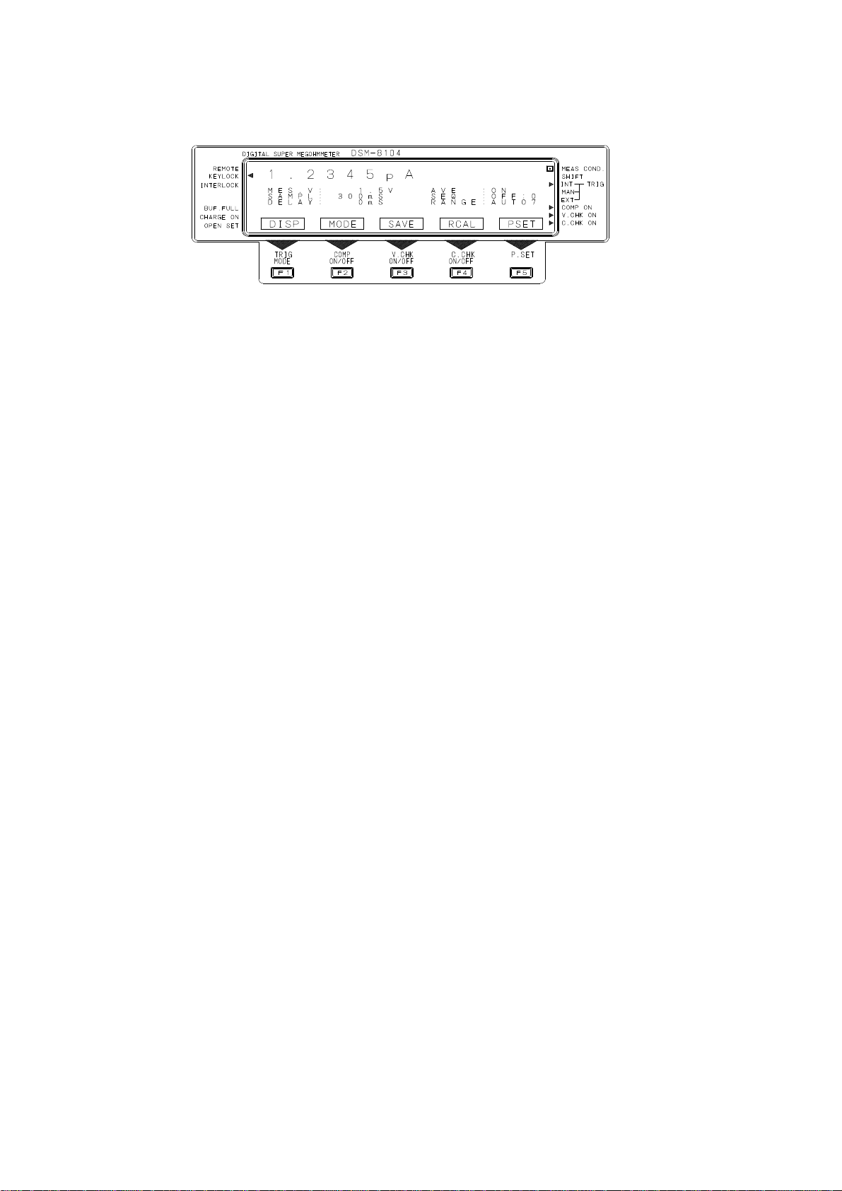
4.2 Front Panel
The front panel of the DSM-8104 is illustrated below.
1: “POWER” switch
The power supply switch to select power on and off.
Press this switch once to depress it to turn the power on. Press once again to pull
up the key and to turn the power off.
2: “POWER” lamp
Lit when the POWER switch is turned on.
3: “STOP” lamp
Lit when the [STOP] key is pressed. Extinguished when the [START] key is pressed.
The output voltage lowers to “0” while the “STOP” lamp is lit, disabling receiving of
trigger input.
4: “START” lamp
Pressing the [START] key lights up this lamp, going off when the [STOP] key is
pressed.
The set voltage is output and trigger input can be received while the “START” lamp is
lit.
5: [STOP] key
Stops measurement and lowers voltage output to 0V.
This key is given the highest priority and can be operated even when the keys are
locked.
6: [START] key
This key outputs set voltage and enables trigger input.
Measurement is started when the Trigger mode is “INT.”
7: “High Voltage” lamp
Indicates output of high voltage.
The lamp is lit when voltage higher than about 30V is output.
8: Cursor moving keys
The keys move the cursor around on the screen or scroll the screen.
12
Page 23

9: Command/numeric input keys
Operate the keys when setting parameters.
Pressing the [SHIFT] key changes the keys to the numeric input keys.
10: [F1]/“TRIG MODE” [F2]/“COMP ON/FF”
[F3]/“V. CHK ON/OFF” [F4]/“C. CHK ON/FF”
[F5]/“P.SET”
These keys are the function keys. The functions of these keys are displayed on the
LCD screen above the keys. Pressing the [SHIFT] key on the measurement screen
sets the functions indicated in “ .” The information is displayed on the screen also.
11: Display
This is a liquid crystal display module 240 x 64 dots in resolution to display measured
results, measuring conditions and various setting screens.
12: “INPUT” connector
The connector for measurement input.
The connector of a double structure comprising a center conductor and outer
conductor connecting to measurement input and the “GUARD” terminal, respectively.
13: “GUARD” terminal
A guard terminal of the measurement input unit.
14: “GROUND” terminal
A grounding terminal connected to the housing of the meter.
15: “OUTPUT” terminal
A terminal for measuring voltage output.
Resistance is measured between the “OUTPUT” and “INPUT” terminals.
16: “CHARGE” terminal
The charging output terminal for precharging. The same level of voltage as that of
measuring voltage is output between the “CHARGE” and “OUTPUT” terminals.
13
Page 24

4.3 Rear Panel
The rear panel of the DSM-8104 is illustrated below.
17: “AC LINE 50/60Hz” connector
The connector for input of power supply voltage.
18: “GND” terminal
The grounding terminal connected to the housing of the meter.
19: “GP-IB” connector
The connector for GP-IB connection.
20: “RS-232” connector
The connector for RS-232 connection.
21: “HANDLER” connector
The connector for handler connection.
22: “INTERLOCK” connector
The input connector for connection of signals from a fixture when an interlock function
is used.
23: “EXT TRIGGER” connector
The connector for external trigger input.
This connector is used when the trigger mode is set to external “EXT.”
24: Cooling fan
The fan for cooling the inside of the meter.
25: “LAN” connector (option)
The connector for LAN connection.
26: Holes for mounting remodeled connector (special order)
Holes for a custom connector of special order.
14
Page 25

4.4 Command/Numeric Input Keys
The command/numeric input keys have the following functions:
[SHIFT]: Shift
The key to change command/numeric input and the functions of the function
keys on the measurement screen.
The command/numeric input keys are set to the Command Input mode when the
[SHIFT] key is not pressed, set to the Numeric Input mode when the [SHIFT]
key is pressed.
Each pressing of the [SHIFT] key alternately changes the mode of the key.
When the SHIFT key is pressed, a side mark (“◄”) will be displayed beside
“SHIFT” in the upper right of the screen.
[ENTER]: Enter
Pressing this key enters input results.
Exit after finishing setting the measurement screen and the setting screen by
pressing this key.
[LOCK]/”0”: Key lock
Press this key to prohibit key input.
Pressing this key prohibits operations of the keys other than the [STOP] and
[LOCK] keys.
Press the [LOCK] key again to cancel the key lock status.
When the keys are locked, a side mark (“◄”) will be displayed beside “KEY
LOCK” in the upper left of the screen.
The key becomes a key for input of “0” when the [SHIFT] key is pressed and
the Numeric Input mode is set.
[LCDOF]/“.”: LCD off
The key to exit the display screen. The key shuts down screen display and
extinguishes the backlight.
Press any key to cancel when the display is turned off.
The key becomes a decimal point input key “.” in the Numeric Input mode.
[MAN.T]/“-”: Manual trigger
A trigger is generated and measurement is started when pressed while the
trigger mode is “MAN” (Manual Trigger mode).
When in the Numeric Input mode, the key will become a negative “-” polarity
input key.
7
MONI
4
MOD
1
PROG
0
LOCK
8
COMP
5
ELEC
2
OPEN
.
LCDOF
9
DATA
6
SETUP
3
V.CHK
-
MAN.T
SHIFT
E
LOCAL
BS
C.CHK
ENTER
15
Page 26

MONI
MOD
PROG
0
LOCK
[PROG]/“1”: Program
The key to move to the sequence program creation screen.
See “Operating Program Creation Screen.”
When in the Numeric Input mode, the key will become an input key (“1”).
[OPEN]/“2”: Open correction
The key to move to the screen to set reference values for contact checks.
See “Operating Open Setting Screen.”
When in the Numeric Input mode, the key will become an input key (“2”).
[V. CHK]/“3”: Voltage check
The key to execute once a voltage check of measuring voltage output between
“OUTPUT” and “GUARD.”
When in the Numeric Input mode, the key will become an input key (“3”).
[C. CHK]/“BS”: Contact check
The key to execute once a contact check.
When in the Numeric Input mode, the key will become a “BS (back space)” key
to delete characters that are input.
[ΔMOD]/“4”: Deviation Measuring mode
The key to move to the Deviation Value Display and Setting screen.
See “Operating Deviation Value Display and Setting Screen.”
When in the Numeric Input mode, the key will become an input key (“4”).
[ELEC]/“5”: Electrode
The key to move to the Electrode Parameter Setting screen.
See “Operating Electrode Setting Screen.”
When in the Numeric Input mode, the key will become an input key (“5”).
[SETUP]/“6”: Set up
The key to move to the Operation Environment Setting screen.
See “Operating Operation Environment Setting Screen.”
When in the Numeric Input mode, the key will become an input key (“6”).
[LOCAL]/“E”: Local
The key to cancel the Remote mode.
When in the Numeric Input mode, the key will become an exponent display and
input key (“E”).
7
4
1
8
COMP
5
ELEC
2
OPEN
.
LCDOF
9
DATA
6
SETUP
3
V.CHK
-
MAN.T
SHIFT
E
LOCAL
BS
C.CHK
ENTER
16
Page 27

[MONI]/“7”: Monitoring
The key to change over the Regular Measurement screen and Sequential
Measurement monitoring screen.
When in the Numeric Input mode, the key will become an input key (“7”).
[COMP]/“8”: Compare
The key to move to the Comparison Measurement Setting screen.
When in the Numeric Input mode, the key will become an input key (“8”).
[DATA]/“9”: Data
The key to move to the acquired data screen to total measured results.
When in the Numeric Input mode, the key will become an input key (“9”).
7
MONI
4
MOD
1
PROG
0
LOCK
8
COMP
5
ELEC
2
OPEN
.
LCDOF
DATA9SHIFT
6
SETUP
3
V.CHK
-
MAN.T
E
LOCAL
BS
C.CHK
ENTER
17
Page 28
4.5 Display Screen
The display screen of the DSM-8104 is illustrated below.
“REMOTE”
When in the Remote mode (GP-IB or RS-232 mode), a side mark (“◄”) will be
displayed on the screen.
The Remote mode is not set when the side mark is not displayed.
“KEY LOCK”
When in the Key Lock mode, a side mark (“◄”) will be displayed on the screen.
The Key Lock mode is not set when the side mark is not displayed.
“INTERLOCK”
When the interlock function is on (enabled), a side mark (“◄”) will be displayed
on the screen.
The interlock function is off (disabled) when the side mark is not displayed.
“BUFF. FULL”
A side mark (“◄”) will be lit when the number of data groups saved by the
buffering function for 1000 data groups exceeds 1000. Measured data after
this mark is lit will be discarded without being stored in the buffer.
“CHARGE ON”
A side mark (“◄”) will be lit when the [CHARGE] terminal is usable. The
[CHARGE] terminal cannot be used when this mark is not lit.
“OPEN SET”
A side mark (“◄”) will be lit when open correction is executed. A contact
check can be carried out while this mark is displayed.
Executing a contact check when this mark is not displayed results in an error.
“MEAS COND”
A side mark (“•”) on the screen indicates that the meter is conducting
measurement.
“SHIFT”
A side mark (“►”) on the screen indicates the status of the Shift key.
The Shift mode is not set while the side mark is not displayed.
18
Page 29

“TRIG-INT”
When in the Internal Trigger mode, a side mark (“►”) will be displayed on the
screen.
“TRIG-MAN”
When in the Manual Trigger mode, a side mark (“►”) will be displa yed on the
screen.
“TRIG-EXT”
When in the External Trigger mode, a side mark (“►”) will be displayed on the
screen.
“COMP ON”
A side mark (“►”) on the screen indicates the ON/OFF status of the decision
function. The decision function is not on when the side mark is not displayed.
The side mark flashes when a decision result is NG.
“V. CHK ON”
A side mark (“►”) on the screen indicates the ON/OFF status of the voltage
check function. The voltage check function is not on when the side mark is not
displayed.
The side mark flashes when the result of a voltage check is NG.
“C. CHK ON”
A side mark (“►”) on the screen indicates the ON/OFF status of the contact
check function. The contact check function is not on when the side mark is not
displayed.
The side mark flashes when the result of a contact check is NG.
19
Page 30

5 Preparations for Measurement
5.1 Setting Measuring Conditions
The meter is capable of setting measuring methods and measuring conditions
beforehand so that insulation resistances of materials, parts and circuits can be
measured easily under preset conditions.
Before explaining about measurement, this chapter describes setting of various
measuring conditions.
Press the “POWER” switch on the front panel to set it to “ON.” The “POWER” lamp on
the front panel lights up.
After initializing, the regular measurement screen sets. Measuring condition settings
such as measuring voltage and sampling time are set to the same states as those stored
when the power was shut down after previous measurement thanks to the resume
function.
[Warning]
Before turning the power on, check that the AC power supply voltage to be
used matches the power supply voltage specified on the rear panel.
If they do not match, a fire or damage to the meter may result.
[Warning]
Be certain to ground the grounding pin of the power cable or a grounding
wire to prevent an accident. If the grounding pin of the power cable or
grounding wire cannot be grounded, ground the grounding terminal located
on the rear of the meter.
Self-diagnosis
After switching the “POWER” on, press the SETUP (SET
display screen. This will take you to the screen to set the operation environment
(Operation Environment Setting screen).
Press the [F2] SELF (SELF
The screen will change to the Self-diagnosis Execute screen. (See Fig. 5.1)
SELF CHECK EXECUTE
1.MEMORY CHECK---
2.A/D CAL.-------
3.RANGE CAL.-----
CHECK) key on the Operation Environment Setting screen.
UP) key in the measured value
EXEC
Fig. 5.1 Self-diagnosis Execute Screen
20
Page 31

A
SELF CHECK EXECUTE
1.MEMORY CHECK---OK
2.A/D CAL.-------OK
3.RANGE CAL.-----OK
EXEC
Fig. 5.2 Self-diagnosis Execute Screen
The function key [F5] will change to EXEC (EXEC
starts self-diagnosis.
In a self-diagnosis test, a memory check, as well as self-calibration checks of the A/D
converter and range, are automatically carried out, displaying OK (acceptable) or NG
(not acceptable). Fig. 5.2 shows an “OK” execution result on the Self-diagnosis Execute
screen.
Press the [ENTER] key after finishing self-diagnosis to return to the measurement
screen.
[Notice]
fter executing self-diagnosis, if there are any items with [NG], switch on the
POWER again and execute the self-diagnosis one more time. If there are still
items with [NG] even after the power is resumed and a self-diagnosis test is
executed, please contact the nearest HIOKI office for repair.
[Notice]
In addition to a [Self-diagnosis function], this meter has a [Self-calibration
function] which allows users to execute self-calibration checks at preset
intervals. The factory default settings are [Self-calibration function = ON] and
[Self-calibration interval = 60 seconds].
The self-calibration check requires about 2 seconds to complete and during
this interval, not only will the measured values not be displayed, but all
controls, including key operations and communications, will also be stopped for
the self-calibration to be executed. Therefore, when executing an automated
measurement, set the self-calibration function OFF and execute a command
from the interfaces GP-IB or RS-232C ([*CAL?] command or [*TST?]
command) to execute self-calibration, or perform a self-diagnosis test by
keying the keys on the panel periodically.
*[Self-calibration] executes [2. Calibration of A/D converter] and [3. Range
calibration] of [Self-diagnosis]. For details on self-calibration, please refer to
[10.3 Self-calibration Function].
UTE). Pressing the [F5] EXEC key
21
Page 32
5.1.1 Screen types
n
Set the various measuring conditions and other items in accordance with the screen on
the front panel.
Two screens are available - Measured value display screen and setting screen.
(a) The Measured Value Display screen displays results of measurement.
(b) The setting screen is for setting measuring conditions and other items.
Table 5.1 Screen Types
Screen Type Screen Meter Status
Measured value
display screen
Setting screen Comparison Measurement Setting screen
• A measured value is displayed in the top part of the screen in large characters.
Measured values are a lways results of most recent measurement.
• Measuring conditions that are currently set are displayed under a measured value.
• Side marks are displayed on both sides of the screen indicating measurement and key
statuses.
• Functions of the function keys are displayed in the bottom.
(1) Measured Value Display screen
The Measured Value Display screen displays measured results and measuring
conditions.
A measured value is displayed in the top part of the screen in large characters.
Measured values that are displayed are always results of most recent
measurement.
The Measured Value Display screen is split into the Regular Measurement
screen and Sequential Measurement Monitoring screen.
In addition to the Regular Measurement screen, the Sequential Measurement
Monitoring screen allows monitoring of the progress of each sequence.
The Monitoring screen counts down the following items as the sequences
advance, enabling viewing of sequence progresses at a glance.
Regular measurement screen Measuring/waiting for key
input
Sequential Measurement Monitoring
screen
Acquired Data screen
Histogram Display screen
Histogram Threshold Display screen
Measured Data Buffer Display screen
Measured Data Buffer Erase screen
Deviation Value Display and Setting scree
Electrode Constant Setting screen
Environment Setting screen
External Interface Setting screen
Self-diagnosis Test Execute screen
Self-calibration Setting screen
Measuring Power Source Setting screen
Program Create screen
Open Correction Value Setting screen
Measuring/waiting for key
input
Waiting for key input
Waiting for key input
Waiting for key input
Waiting for key input
Waiting for key input/display
Waiting for key input
Waiting for key input
Waiting for key input
Waiting for key input
Waiting for key input
Waiting for key input
Waiting for key input
Waiting for key input
Waiting for key input
After measurement/waiting
for key input
22
Page 33

Operate the [MONI] key to switch between the [Regular Measurement screen]
and [Sequential Measurement Monitoring screen].
Measuring condition display Side mark display Measured value display Side mark display
REMOTE
KEYLOCK
INTERLOCK
BUF.FULL
CHARGE ON
OPEN SET
◄ □
3.0000E+10Ω
◄ ►
MES.V:100.0V AVE :ON
SAMPL:15PLC SEQ :OFF:1
DELAY: 0ms RANGE:AUTO1
◄ ►
DISP MODE SAVE RCAL <PSET> ►
MEAS COND
SHIFT
INT TRIG
MAN
EXT
COMP ON
V.CHK ON
C.CHK ON
[Regular Measurement screen] Function key display
Press the [MONI] key for changeover
[Sequential Measurement Monitoring screen]
REMOTE
KEYLOCK
INTERLOCK
BUF.FULL
CHARGE ON
OPEN SET
◄ □
3.0000E+10Ω
◄ MES.V:100.0V SEQ :ON:0 ►
SAMPL: 15PLC DCHG1: 10.0s
DELAY: 0ms CHARG: 10.0s
AVE :OFF MEAS : 2.0s
◄ RANGE:AUTO1 DCHG2: 10.0s ►
DISP MODE SAVE RCAL <PSET> ►
MEAS COND
SHIFT
INT TRIG
MAN
EXT
COMP ON
V.CHK ON
C.CHK ON
Fig. 5.3 Regular Measurement screen and Sequential Measurement Monitoring screen
23
Page 34

Table 5.2 Display of Measured Values
Classification Display Setting Procedure
Indication
type
Number of
Unit indication
Exponential indication
[F1]DISP ⇒ [F1]UNIT
[F1]DISP ⇒ [F2]EXP.
2 to 5 columns [F1]DISP ⇒ [F3]FIG
effective digits
Measuring
mode
Deviation
value display
Ω: Resistance measurement
A: Current measurement
ΩRs: Surface resistivity measurement
ΩRv: Volume resistivity measurement
Measured value - Reference value
Measured value - Reference value
Reference value
X100%
Press the [F2] MODE key to
sequentially select a desired
mode
Ω → A→ ΩRs → ΩRv→ Ω
Select [MOD] and DEV
Select [MOD] and PAR
Error display RANGE OVER: Overrange in current measurement*
*An [RANGE OVER] display indicates a measurement value which is beyond the preset
measurement range (resistance value of the measurement object is too low). An
[RANGE OVER] display during Auto Range will mean that the value is beyond the
measurable range.
Table 5.3 Meanings of Side Marks
Panel
Character
REMOTE
KEY LOCK
INTERLOCK
BUF.FULL
CHARGE ON
OPEN SET
MEAS COND
SHIFT
TRIG INT
MAN
EXT
COMP ON
V.CHK ON
C.CHK ON
Side
Status
Mark
◄ In external remote mode
◄ In key lock mode
◄ Interlock in operation ([START] disabled)
◄ Data buffer is full
◄ “CHARGE” terminal can be used
◄ Open correction already executed
□ In measurement
► Key shift mode (Numeric and other keys can be input)
►
Internal trigger is selected
►
Manual trigger is selected
►
External trigger is selected
► Comparison measurement is selected
The side mark flashes if a comparison result is NG.
► Voltage check is executed automatically
The side mark flashes if result of voltage check is NG.
► Contact check is executed automatically
The side mark flashes if result of contact check is NG.
NOTE 1
NOTE 1
NOTE 1
Note 1:
When a mark is flashing in case a result is NG, the mark does not go off till next
check is carried out or a decision is made.
24
Page 35

Set the measuring conditions for the Measured Value Display screen as follows.
(a) Press the [F5] RESET key.
(b) Move the cursor to a desired setting item operating the cursor move keys ([◄], [►],
[▲] and [▼]). The selected items will be highlighted.
(c) Operate the function keys corresponding to the screen display or the numeric keys
for setting each item. Select each setting by pressing the [ENTER] key.
When canceling a setting, erase a numeric value by pressing the [BS] key and press
the [ENTER] key to return to data before the setting.
The functions keys corresponding to each setting item will be the scroll keys ([F2],
[F3]) for specified value. Condition setting keys for each function will be [F4] and
[F5].
See Table 5.4 for more information.
[Example] To set voltage 75.5V.
(a) Press the [F5] PSET key.
(b) Move the cursor to “MES. V” operating the [◄], [►], [▲] and [▼] keys.
(c) Voltage cannot be specified operating the [F2] DOWN and [F3] UP keys. Input
voltage by keying the numeric keys.
(d) Set by sequentially keying the “7” [MONI], “5” [ELEC], “.” [LCDOF], “5” [ELEC] and
[ENTER] keys.
25
Page 36

Table 5.4 Measuring Conditions
Set Item Description
MES.V Set voltage
range
Setting Range (Specified Value)
0.1 ~ 250 V
251 ~ 1000 V
*3
Resolution
0.1 V
1 V
[ F2 ] DOWN
[ F3 ] UP
(0.1,0.5,1.0,2.5,5.0,10,25,
50,100,250,500,1000)
SAMPL Integral time Time setting 2 ~ 300 ms
(2,4,8,16,20,40,80,160,300)
Period setting 1 ~ 15 PLC
(1,2,4,8,15)
DELAY Trigger delay
time
0 ~ 9999 ms
(0,5,10,50,100,500,1000,
*1
1 ms
1 PLC
[ F2 ] DOWN
[ F3 ] UP
[ F4 ] ms
[ F5 ] PLC
1 ms [ F2 ] DOWN
[ F3 ] UP
5000,9999)
AVE Averaging ON/OFF [ F4 ] ON
[ F5 ] OFF
RANGE Current range
Range 1 ~ 8 AUTO/HOLD
Range Integral Capacity
1 10 µF
2 1 µF
[ F2 ] DOWN
[ F3 ] UP
[ F4 ] AUTO
[ F5 ] HOLD
3 100 nF
4 10 nF
5 1 nF
6 100 pF
7 10 pF
8 10 pF
*2
SEQ Sequential
measurement
Program No. 0 ~ 9
ON/OFF
[ F2 ] DOWN
[ F3 ] UP
[ F4 ] ON
[ F5 ] OFF
DCHG1 Discharging
time
0 ~ 999.9 s
(0,10,20,30,40,50,60,600,900)
0.1 s [ F2 ] DOWN
[ F3 ] UP
(Before
measurement)
CHARG Charging time 0 ~ 999.9 s
(0,10,20,30,40,50,60,600,900)
MEAS Measuring
time
DCHG2 Discharging
time
0 ~ 999.9 s
(0,10,20,30,40,50,60,600,900)
0 ~ 999.9 s
(0,10,20,30,40,50,60,600,900)
0.1 s [ F2 ] DOWN
[ F3 ] UP
0.1 s [ F2 ] DOWN
[ F3 ] UP
0.1 s [ F2 ] DOWN
[ F3 ] UP
(After
measurement)
NOTES
*1: “1 PLC” stands for “1 power line cycle.”
*2: “Range 8” increases the gain ten-fold while maintaining the same capacitor capacity
of 10pF.
*3: The specified value is a preset value selected by the scroll keys.
26
Page 37

Measuring conditions are set on the Measured Value Display screen after pressing the
[F5] PSET key. To facilitate settings and to enable selection of a value operating the
function keys [F2] to [F5], a specified value is given to each condition.
To reset after finishing setting, press the [ENTER] key.
(2) Setting screen
As shown in Fig. 5.4, the setting screen is displayed by moving from the
Measured Value Display screen to the Setting screen in accordance with a
measuring condition or other items.
The Setting screen has a dedicated screen for each set item.
To reset to the Measured Value Display screen, press the [ENTER] key.
Measured Value Display screen Setting screen
Regular
measurement
screen
Change by
pressing
the [MONI]
key
Sequential
Measurement
Monitoring screen
Fig. 5.4 Key Operation and Screen Change
Table 5.5 Setting keys and function keys for setting screen change
Setting Key Function Key Setting Screen
Reset by pressing the
[ENTER] key
Move to the setting
screen operating setting
and function keys.
Cannot measure on this
screen
[ COMP ]
[ DATA ]
[ F1 ] HIST
[ F2 ] SETH
[ F3 ] CLRH
[ F4 ] CLRD
[ F5 ] ROLL
[ △ MOD ]
[ ELEC ] Electrode Setting screen (See 6.3.3)
[ SETUP ]
[ F1 ] CONF
[ F2 ] SELF
[ F3 ] CAL
[ F4 ] POWR
[ PROG ] Program create screen (See 5.1.9)
[ OPEN ] Open Correction Value Setting screen (See 6.7.2)
Comparison Measurement Setting screen (See 5.2.2)
Acquired Data screen (See 5.2.4 onward)
Histogram display screen
Histogram display threshold setting screen
Histogram counter clear screen
Measured data buffer clear screen
Measured data buffer display screen
Deviation Value Display and Setting screen (See 5.2.3)
Environment Setting screen (See 5.1.12 onward)
External interface setting screen
Self-diagnosis test execute screen
Self-diagnosis test execute screen
Self-calibration setting screen
27
Page 38

5.1.2 Setting measuring mode
This meter has four measuring modes capable of measuring resistance, current, surface
resistivity and volume resistivity.
Set a desired measuring mode as follows.
(1) Key operation
(a) Press the [F2] MODE key for mode selection.
(NOTE: The modes are displayed on the Measured Value Display screen.)
(b) Each pressing of the [F2] MODE key sequentially selects resistance
measurement, current measurement, surface resistivity measurement and
volume resistivity measurement.
(2) Mode display
The individual measuring modes are displayed in the units displayed in the
measured value display section.
Measuring Mode Unit Indication
Resistance measurement Ω
Current measurement A
Surface resistivity measurement Ω
Rs
Volume resistivity measurement Ω Rv
[Notice]
The actual unit for surface resistivity measurement is [Ω].
The actual unit for volume resistivity measurement is [Ω·cm] .
5.1.3 Setting measuring voltage
(1) Keying
(a) Press the [F5] PSET key on the Regular Measurement screen or the
Sequential Measurement Monitoring screen shown in Fig. 5.3 to enter into
the Measuring Condition Setting mode.
(b) Input voltage after moving to “MES. V:” operating the cursor moving keys
([◄], [►], [▲] and [▼ ]).
Voltage can be input by directly inputting on the numeric keys or by selecting
from the following preset values.
(c) The [F2] and [F3] keys perform the DOWN and UP functions respectively in
the Measuring Condition Setting mode, to sequentially change preset fixed
values.
The following fixed values are preset:
12 values: 0.1, 0.5, 1.0, 2.5, 5.0, 10, 25, 50, 100, 250, 500 and 1000
28
Page 39

5.1.4 Setting current limiter
This meter limits a current to the work by a current limiter to expedite charging to the
work and to prevent fracture of the work.
The “CHARGE” terminal is provided to facilitate precharging in auto measurement. The
current to the “CHARGE” terminal is also limited by a current limiter.
These current limiters are set through “POWER SOURCE SELECT” on the setting screen
by the [SETUP] key.
“POWER SOURCE SELECT” also sets “CHARGE” output and the filtering function, in
addition to the current limiters.
[Caution]
The current limiter limits a steady-state current. A transient current several
ten μs in width flows when the sample is changed by a relay or other means.
When changing the measuring terminal by a relay or other means while
outputting measuring voltage, serially insert protective resistance not
exceeding the maximum permissible current of the contact to limit the current
flow in the contact for protection of the relay contact.
This procedure is also repeated when changing the “CHARGE” terminal for
precharging.
Protective resistance value ≧ (measuring voltage)/(maximum permissible curre nt)
(1) Keying
(a) Press the [SETUP] key to set up the Setting screen.
(b) Press the [F4] POWR key to set up the “POWER SOURCE SELECT” screen.
(c) Move to “CURL :” operating the vertical cursor moving keys [▲] and [▼] and
select a limit value operating the horizontal cursor moving keys [◄] and [►].
(d) Move to “CURL C:” operating the vertical cursor moving keys [▲] and [▼]
and select (Use/Non-use) for the “CHARGE” terminal operating the
horizontal cursor moving keys [◄] and [►].
(2) Limit value setting range
The limit value setting range is limited as follows depending on the measuring
voltage:
Measuring voltage: 0.1 to 250V, 5mA/10mA/50mA
250V to 1000V, 5mA/10mA
(3) Selecting “CHARGE” terminal
Set “CURL C:” to ON and set “CURL :” to “10” or “50.” The “CHARGE” terminal
can then be used and a side mark “◄” lights up near “CHARGE ON” on the
panel.
The limit currents of the current limiters on the measuring side (“INPUT” or
“GUARD”) and on the charge side (“CHARGE”) will be set as shown in Table
5.6.
29
Page 40

Table 5.6 Set Values of Current Limiters
“CURL :” Setting 5mA 10mA 50mA
“INPUT” side 5mA 10mA 50mA “CURL.C:”
OFF
“CHARGE” side 0 0 0
“INPUT” side 5mA 5mA 5mA “CURL.C:”
ON
“CHARGE” side 0 5mA 45mA
(4) Power noise filter setting
Set in “FILTER:OFF/ON.”
OFF: The filter is not used. (High-speed changeover mode: Fast)
ON: The filter is used. (Low-noise mode: Slow) [Standard setting]
(5) Power source noise filter
Noise of measuring voltage output greatly affects the measurement accuracy in
measurement of samples which have a high electrostatic capacity such as
capacitors. For this reason, the meter is equipped with a filter to reduce noise
of measuring voltage output.
In regular measurement, stable measurement is possible by turning a filter on.
The condition in which the filter is turned on is called the “low-noise mode.”
The low-noise mode enables stable measurement with less noise. However,
one disadvantage with this mode is that the changeover speed of measuring
voltage becomes slow depending on the filter response time.
Select the high-speed changeover mode with the filter turned off in
measurement that requires fast changeover of measuring voltage.
The low-noise mode with the filter turned on is set during preshipment
inspection of the meter at the HIOKI factory.
5.1.5 Setting measuring range
The meter consists of a high-sensitivity current measuring unit and a measuring voltage
output unit and calculates an insulation resistance value based on a measured current
value and measuring voltage.
The measuring range of the meter indicates a current measuring range of the current
measuring unit, rather than a resistance measuring range. There are eight current
measuring ranges for the current measuring unit. The full-scale sensitivity of each
range is decided by the integral time setting.
The full-scale current value is expressed roughly by the following formula. (10mA is
maximum)
I
where I
= 3 x 10
FS
full-scale current value, R: range and T: integral time
FS:
-(4 + R)
/T
Table 5.7 shows the relationship between typical integral times and full-scale sensitivities
of the various ranges.
Range changeover enables setting of auto changeover and fixed range.
30
Page 41

(1) Keying
(a) Press the [F5] PSET key to set the Measuring Condition Setting mode.
(b) Move to “RANGE:” operating the cursor moving keys [◄], [►], [▲] and [▼].
(c) Set “AUTO/HOLD” by operating the [F4] AUTO and [F5] HOLD keys.
(d) In case “H OLD” is set, operate the [F2] DOWN and [F3] UP keys and set a
range.
“AUTO” sets auto changeover and “HOLD,” a fixed range.
“DOWN” changes the range toward low current sensitivity and “UP,” toward
high current sensitivity.
Table 5.7 Integral Time and Full-scale Current Values of Various Ranges
Range
Code
5.1.6 Setting integral time (sampling time)
Stable high-sensitivity current measurement is sometimes disabled due to impacts of
noise components contained in the input current. This meter performs A/D conversion
after integrating the input current to remove noise components for stable measurement.
The noise removal rate increases longer the integral time is and power source noise
(ham) can be greatly removed by increasing the integral time by integer multiplication of
the power source period.
A long integral time also increases the measuring time. Set an appropriate integral time
depending on measured resistance value (current value) referring to 5.1.5 Setting
measuring range.
The integral time can be set in increment of 1ms or 1PLC.
(1) Keying
(a) Press the [F5] PSET key to set up the Measuring Condition Setting screen.
(b) Move to “SAMPL:” operating the cursor moving keys [◄], [►], [▲] and [▼]
(c) [F4] and [F5] keys become the keys to select ms and PLC respectively. The
2ms 10ms 20ms 100ms 300ms
1 10mA 3.0mA 1.5mA 300µA 100µA
2 1.0mA 300µA 150µA 30µA 10µA
3 100µA 30µA 15µA 3µA 1µA
4 10µA 3.0µA 1.5µA 300µA 100nA
5 1.0µA 300nA 150nA 30nA 10nA
6 100nA 30nA 15nA 3nA 1nA
7 10nA 3.0nA 1.5nA 300pA 100pA
8 1.0nA 300pA 150pA 30pA 10pA
and input an integral time.
[F2] and [F3] keys change to the DOWN and UP functions respectively.
Integral Time
31
Page 42

(c) Press the [F4] ms key to set input in the unit of ms, allowing setting of
integral time in increment of 1ms. The [F5] PLC key allows input in the unit
of PLC, allowing settings in increment of 2ms to 300ms and in increment of 1
to 15PLC.
[Note]
“PLC” stands for “one power line cycle” and is about 17ms at 60Hz and 20ms
at 50Hz.
[Notice]
Setting of an integral time changes the full-scale sensitivity of the current
measuring unit. Refer to 5.1.5 “Setting measuring range.”
5.1.7 Setting averaging function
The averaging function curbs dispersions of measured values by averaging measured
results.
This function is enabled when the Trigger mode is internal trigger ([INT]).
(1) Keying
(a Press the [F5] PSET key to set the Measuring Condition Setting screen.
On the Measuring Condition Setting screen, the [F4] and [F5] keys change to
keys that select ON and OFF, respectively.
(b) Move to “AVE:” operating the cursor moving keys [◄], [►], [▲] and [▼].
Set by keying the [F4] ON and [F5] OFF keys.
5.1.8 Setting trigger mode
This meter has three trigger modes, namely, the Internal Trigger [INT], Manual Trigger
[MAN] and External Trigger [EXT] modes.
Select a suitable mode in accordance with the operation.
(1) Keying
(a) Press the [SHIFT] key to set to the Shift mode. The [F1] key changes to
TRIG.
(b) Each pressing of the [F1] TRIG key alternately changes the trigger mode of
the key to the Internal Trigger [INT], Manual Trigger [MAN] and External
Trigger [EXT] modes.
The trigger mode is indicated by a side mark (“◄”) on the right of the screen.
(2) Trigger mode operation
The meter operates in each trigger mode as shown in Table 5.8.
32
Page 43

Table 5.8 Operation in Trigger Modes
Trigger Mode Operation
Internal Trigger
[INT]
Manual Trigger
[MAN]
External Trigger
[EXT]
(3) Trigger mode change
Each pressing of the [F1] TRIG key alternately changes the trigger mode to
Internal Trigger, Manual Trigger and External Trigger modes.
A side mark (“►”) indi cates a trigger mode that is selected.
Internal Trigger ► INT TRIG
Manual Trigger MAN
External Trigger EXT
(Note: Example for internal trigger)
5.1.9 Creating a program
A program can be set for sequential measurement that will be useful when the time for
impressing measuring voltage accurately to the sample needs be controlled accurately.
Sequential measurement presets the following items and enables inspection under the
same conditions.
(1) Discharge 1: Set a discharging time before impressing voltage.
(2) Charge: Set a time for impressing voltage before starting measurement.
(3) Measurement: Set a time for measurement.
Measured values after these set times are output.
(4) Discharge 2: Set a discharging time after finishing measurement.
[Warning]
Residual measuring voltage sometimes still remains inside the sample after
measurement is finished when high voltage is impressed in manual measurement.
Removal of a sample immediately after measurement is hazardous as there is a
risk for an electrical shock. Set a time for Discharge 2 and remove a sample
after sample is thoroughly discharged.
[Notices]
1. When shut down, the DSM-8104 is always in a discharge state. Set Discharge
1 when necessary taking the jig and scanner that have contacted the outside
into consideration. Discharge 1 is almost irrelevant when the DSM-8104 is
used independently.
2. The state between the measuring input terminal and [OUTPUT] terminal in a
discharging condition (also during a shutdown) is the one to which a circuit that
has a set current limiter and input resistance (about 100Ω) of the current
measuring unit in series is connected.
Measurement is performed continuously on timing
generated inside the meter.
Performs one measurement when the [MAN.T] key is
pressed on the panel or a trigger GP-IB command is
input.
Performs one measurement when trigger input is
made to “EXT TRIGGER” input in the rear from the
outside.
33
Page 44

Set the sequence program as follows.
(1) Press the [PROG] key on the Measurement screen.
The following Sequence Program Creation screen will be displayed.
MAKE SEQUENCE PROGRAM
PROGRAM No. :[0]
DISCHG1 :[ 0.0]SEC
CHARGE :[ 0.0]SEC
MEAS TIME :[ 0.1]SEC
DISCHG2 :[ 0.0]SEC
DOWN UP
Fig. 5.5 Sequence Program Creation Screen
The Function keys [F2] and [F3] will respectively change to the DOWN and UP functions.
A preset value can be chosen keying the DOWN and UP keys in addition to directly
inputting it through the numeric input keys.
After finishing setting, return to the Measurement screen by pressing the [ENTER] key.
(2) Program No. setting
Input in “PROGRAM NO.” a program No. for a program to be created.
Ten types of sequence programs, 0 to 9, can be created.
(3) Charging time, measuring time and discharging time setting
In sequence program measurement, the operational sequence of DISCHG1 -CHARG -- MEAS TIME -- DISCHG2 cannot be changed.
(a) Setting discharging time before measurement (DISCHG1)
Set a time to discharge the sample before starting measurement.
0 to 999.9s can be set.
(b) Setting charging time before measurement (CHARGE)
Set a time to charge the sample by impressing measuring voltage.
0 to 999.9s can be set.
(c) Setting measuring time (MEAS TIME)
Set a time to measure a sample.
0 to 999.9s can be set.
(d) Setting discharging time after measurement (DISCHG2)
Set a time to discharge the sample after measurement.
0 to 999.9s can be set.
34
Page 45

5.1.10 Setting measured data buffer function
(1) Press the [DATA] key. (MEASURED RESULT DATA
Move to the screen for selecting functions for totaling measured results
(histogram data counter, measured data buffer). (See Fig. 5.14)
(2) Data buffer display ([DATA], ROLL)
Press the [F5] ROLL key (SCROLL
screen. The screen will display the Data Buffer Display screen shown in Fig.
5.6.
MODE:Ω |000:0.0000E+00
ROLL:LINE/PAGE |001:0.0000E+00
|002:0.0000E+00
|003:0.0000E+00
|004:0.0000E+00
|005:0.0000E+00
|006:0.0000E+00
DOWN UP TOP END
DATA BUFFER) on the Function Select
)
Fig. 5.6 Data Buffer Display Screen
Measured values will be displayed sequentially from oldest to newest. Measured values
with numbers suffixed to measured valued are newer larger the numbers are.
The functions of the functions keys on this screen will change to [F2] DOWN, [F3] UP,
[F4] TOP and [F5] END.
In the absence of data in the data buffer, “--- none ---“ will be displayed.
The content in the data buffer will be “+0.0000E+00” in the resistance measuring mode
(includes volume and surface resistivities) and “+9.9999E+99” in the current measuring
mode in case measured results are overrange.
(a) [◄] and [► ] keys
The keys change the number of scroll lines (ROLL: LINE/PAGE)
LINE: In increment of 1 line
PAGE: In increment of 1 page (7 lines)
(b) [F2] DOWN key
Scrolls the screen toward small data No.
(c) [F3] UP key
Scrolls the screen toward large data No.
(d) [F4] TOP key
Moves the screen to the top data No.
(e) [F5] END key
Moves the screen to the last data No.
(f) [ENTER] key
Exits data buffer display and returns to the function selection screen.
(3) Erasing data buffer ([DATA], CLRD)
Press the [F4] CLRD key in the function selection screen. (See Fig. 5.14)
The screen moves to the Data Buffer Erase screen shown in Fig. 5.7.
35
Page 46

CLEAR DATA BUFFER
ADDR:ALL/LMT
SADR:[ ]
EADR:[ ]
EXEC
Fig. 5.7 Measured Data Buffer Clear Screen
On this screen, the function of the function key [F5] changes to EXEC.
Press the [F5] EXEC key to clear data.
(a) [◄] and [►] keys
The keys set an area for data clearing.
ALL: All data erase
LMT: Clearing of data in a specified area (Deletes data in the range
of SADR to EADR)
(b) [▲] and [▼] keys
Select an item for start No. SADR and end No. EADR when the clearing
range is LMT.
Input a data No. within the specified range operating the numeric keys when
setting SADR and EADR. Press the [ENTER] key to enter the input.
(c) Press the [F5] EXEC key to clear data.
(d) Press the [ENTER] key to return to the Function Selection screen. (See Fig.
5.14)
(4) Data buffer usage
The data buffer is useful such as when analyzing data after taking
measurement.
Measurement can be performed relatively quickly if data is fetched collectively
after finishing all measurements since fetching of data for each measurement is
time consuming such as when fetching data using an interface.
Take measurement after erasing data in the data buffer when using the buffer.
Otherwise data separation point cannot be determined because previous data is
still remaining.
Changing the measuring mode during measurement while using the data buffer
disables distinction between saved data and new data.
All data is saved in the buffer in measured current values and is displayed after
converting to a format matching the measuring mode when data is displayed.
Values sometimes cannot be displayed correctly if the measuring mode during
display differs from the measuring mode used during measurement.
36
Page 47

5.1.11 Setting operating environment
Press the [SETUP] (SET UP
The screen changes to the Operating Environment Setting screen. (See Fig. 5.8)
9.9999E+99Ω
MES.V: 0.1V AVE :OFF
SAMPL: 100mS SEQ :OFF:0
DELAY: 0mS RANGE:AUTO1
CONF SELF CAL POWR
Fig. 5.8 Operating Environment Setting Screen
(1) Self-calibration setting
Press the [F3] CAL (CAL
screen.
The screen changes to the Self-calibration Setting screen. (See Fig. 5.9)
CALIBRATION
AUTO MODE:OFF/ON
INTERVAL :[ 60]Sec
) key on the Measurement screen.
IBRATION) key on the Operating Environment Setting
DOWN UP EXEC
The function keys will change to [F2] DOWN, [F3] UP and [F5] EXEC.
Select an item to be set by operating the [▲] and [▼] keys.
After finishing settings, press the [ENTER] key to return to the Measurement
screen.
(2) “AUTO MODE” setting
This function executes self-calibration (self-calibration check of the A/D
converter and range) automatically at a preset time interval.
OFF: Auto self-calibration is not executed.
ON: Auto self-calibration is executed.
(3) “INTERVAL” setting
Set a time interval for auto self-calibration by inputting a time interval operating
the numeric input keys and pressing the [ENTER] key.
Or, a time interval can be selected from among designated values operating the
[F2] DOWN and [F3] UP keys because specified values are already set in the
meter.
Fig. 5.9 Self-calibration Setting Screen
37
Page 48

A time interval between 10s and 9999s can be set as “INTERVAL.”
60s is set with the meter during preshipment inspection at the factory.
The following values are set in advance as specified values.
10, 60, 300, 900, 1800, 3600, 7200 and 9999s
(4) Executing self-calibration check
Press the [F5] EXEC (EXECUTE) key.
This function executes self-calibration once on the Self-calibration screen
regardless of whether or not AUTO MODE is ON or OFF. The display screen
does not change.
[Notices]
1. The measuring time sometimes lengthens the self-calibration execution time
(about 2s) when auto execute is on.
2. Auto self-calibration cannot be performed even when auto execute is set to
ON if sequential measurement is ON.
5.1.12 Setting other items
The following items are set.
Interlock function setting
Beep tone setting
Key click tone setting
GP-IB address setting
RS-232 baud rate setting
RS-232 character length setting
RS-232 parity check setting
RS-232 stop bid length setting
(1) External interface condition setting
Press the [F1] (CONFIGURATION) key on the Operating Environment Setting
screen (see Fig. 5.8).
The screen changes to the External Interface Condition Setting screen. (See
Figs. 5.10 and 5.11)
The External Interface Condition Setting screen is divided into two pages.
CONFIGURATION PAGE-1/2
INTERLOCK:CONECT/CUTOFF
BEEP :OFF/O N
BEEP :NO/GO
CLICK :OFF/O N
PAGE
Fig. 5.10 External Interface Condition Setting Screen 1/2
38
Page 49

CONFIGURATION PAGE-2/2
GPIB ADDR:[ 1]
232 BAUD:4800/9600/19200
232 DATA:7BIT/8BIT
232 PARI:NON/ODD/EVN
232 STOP:1BIT/2BIT
PAGE
Fig. 5.11 External Interface Condition Setting Screen 2/2
The [F5] key changes to the PAGE (PAGE
alternately changes pages.
Select an item to be set by operating the [◄], [►], [▲] and [▼] keys and set it.
The selected item will be highlighted in the display.
(2) Interlock function setting
Select “PAGE-1/2” and set an INTERLOCK: item.
The following function will set.
CONECT: The interlock function will be enabled.
In this case, output of measuring voltage will be enabled if “INTERLOCK” input
in the rear is short-circuited (low level input), prohibiting output of measuring
voltage if open-circuited (high level input).
When disabled, the [START] key will be disabled and a side mark (“◄”) will light
up in the “INTERLOCK” display on the left of the LCD screen.
CUTOFF: Disables the interlock function.
In this case, measuring voltage can always be output irrespective of
“INTERLOCK” input in the rear.
(3) Beep tone setting
Set “BEEP: OFF/ON” and “BEEP: NO/GO” items on “PAGE-1/2.”
OFF: Beep tone is not sounded.
ON: Beep tone is sounded.
NO: Beep tone is sounded if decision is NG.
GO: Beep tone is sounded if decision is GOOD.
(4) Key click tone setting
Set “CLICK: OFF/ON” on “PAGE-1/2.”
OFF:Click tone is not sounded.
ON: Click tone is sounded.
(5) GP-IB address setting
Set “GP-IB ADDR” on “PAGE-2/2.” An address 0 to 30 can be set.
Input an address value operating the numeric input keys and press the [ENTER]
key to set.
) function. Each pressing of the key
39
Page 50

[Note] If a GP-IB address is changed, the status register and mask register will
be initialized. New settings will become necessary.
(6) RS-232 communication condition setting
Set RS-232 communication conditions in “232” items on “PAGE-2/2.”
232 BAUD RS-232C baud rate setting
4800 4800BPS
9600 9600BPS
19200 19200BPS
232 DATA RS-232C character length setting
7- bit length/word
8- bit bit length/word
232 PARI RS-232C parity check setting
NON Parity check not performed
ODD Odd parity check performed
EVE Even parity check performed
232 STOP RS-232C stop bit length setting
1BIT 1 bit
2BIT 2 bits
5.2 Display and Processing of Measured Value
5.2.1 Displaying measured value
Measured values are displayed on the Measured Value Display screen, to display
measured results and measuring conditions. As shown in Fig. 5.3, the Measured Value
Display screen is split into the Regular Measurement screen and Sequential
Measurement Monitoring screen.
(1) Regular Measurement screen
A measured value is displayed in the top part of the screen in large characters.
Measured values are always results of most recent measurement.
Measuring conditions that are currently set are displayed under a measured
value.
Side marks are displayed on both sides of the screen indicating measurement
and key statuses.
Functions of the function keys are displayed in the bottom.
(2) Sequential Measurement Monitoring screen
In addition to the Regular Measurement screen, the Sequential Measurement
Monitoring screen allows monitoring of the progress of each sequence.
The Sequence Monitoring screen counts down the following items as the
sequences advance, enabling viewing of sequence progresses at a glance.
40
Page 51

Discharging time before measurement “DCHG1”
Charging time before measurement “CHARG”
Measuring time “MEAS”
Discharging time after measurement “DCHG2”
The “Regular Measurement screen” and “Sequential Measurement Monitoring
screen” can be changed by operating the [MONI] key.
(3) Changing measured value display format. [F1] DISP (DISP
Change unit indication of measured value and display format of exponential
indication as follows.
The following menu is displayed for the function keys.
Functions UNIT EXP. FIG
Measured value is displayed in unit [F1] UNIT (UNIT
Measured value is displayed in EXPONEN [F2] EXP. (EXP
Number of display columns of measured value is set [F3] FIG (FIG
In display column count setting, “ENTER SIGNIFICANT FIGURE” is displayed in
the bottom of the screen.
Input the number of display columns (2 to 5) through the numeric keys.
Press the [ENTER] key after inputting to enter the selection.
Types and indication methods of measured values are shown in Table 5.2.
Meanings of side marks displayed on the screens are shown in Table 5.3.
LAY)
)
ONENT)
URE)
41
Page 52

5.2.2 Comparison measurement
Set conditions for comparing a measured value with permissible upper-limit and
lower-limit values and for automatically deciding acceptable or not acceptable.
Press the [COMP] (COMP
The screen changes to the screen to set comparison measurement conditions.
(See Fig. 5.12) This function decides whether measured results are large,
small or between upper-limit and lower-limit values after comparing with
upper-limit and lower-limit values and outputs a result by a side mark or to an
external handler interface.
If a comparison result is NG, the side mark (“►”) will flash.
COMPARE MODE PARAMETER
MODE :HI/IN/LO
UPPER:[ 0.0000E+00]Ω
LOWER:[ 0.0000E+00]Ω
Fig. 5.12 Comparison Measurement Setting Screen
Select an item to be set on the setting screen by keying the [▲] and [▼] keys.
The selected item will be highlighted on the screen.
Select a mode by keying the [◄] and [►] keys. Select “HI,” “IN” or “LO.”
Setting of “UPPER” or “LOWER” sets the input status of the numeric keys.
Input a numeric value to be input. Refer to 1) and 2) in the following.
Press the [ENTER] key to finish setting. The screen will return to the
Measurement screen.
(1) Compare Mode setting
Select a range (“HI,” “IN” or “LO”) in which a comparison decision result is
treated as “GO” (acceptable) by operating the “◄” and “►” keys.
Set by operating the “▲” and “▼” keys or by pressing the [ENTER] key.
Pressing the [ENTER] key exits the Setting screen and returns to the
Measurement screen.
Table 5.11 Setting Ranges for Comparison Measurement
HI IN LO
UPPER
LOWER
(2) Setting upper-limit UPPER and lower-limit LOWER
Setting UPPER and LOWER enables input by the numeric keys. Input a value
to be set. The numeric input keys will be enabled automatically without
pressing the [SHIFT] key.
Set the value input by pressing the [ENTER] key.
Press the [ENTER] key to finish setting and to return to the Measurement
screen.
ARE ACTIVE) key.
GO
GO
GO
42
Page 53

The setting ranges for UPPER and LOWER are limited depending on the
measuring mode. See Table 5.12.
Table 5.12 Setting Ranges by Measuring Mode
Measuring Mode Setting Range
Resistance
measurement
Current
measurement
Surface resistivity
measurement
Volume resistivity
measurement
[Notice]
Exercise caution when setting sequences. When setting UPPER and
LOWER, an error results if the condition of (UPPER) > (LOWER) is not
established, disabling keying of the [ENTER] key.
(3) Result display of comparison measurement
The side mark for “COMP ON” on the right in the screen flashes if the decision
result of a comparison measurement is <NG>.
If beep tone output is set, a beep tone will be emitted as a decision result and
the decision result will be output to the connector of the handler interface in the
rear.
[Notice]
Comparison measurement is made only against the absolute value of each
measurement item and comparison against deviation or % cannot be made.
5.2.3 Deviation display
(1) Setting deviation display
Press the [△MOD] (SET D
measurement screen. The screen will change to the deviation (difference or
ratio) display and setting screen. (See Fig. 5.13)
DEVIATION MODE PARAMETER
MODE:OFF/DEV/PAR
REF :[ 0.0000E+00]Ω
1.0000E+01~3.0000E+16Ω
3.0000E-14~1.0000E-02A
1.0000E+01~3.0000E+16ΩRs
1.0000E+01~3.0000E+16ΩRv
EVIATION MODE PARAMETER) key on the
Fig. 5.13 Deviation Display and Setting Screen
(2) Setting Deviation Display mode
Select an item by operating the [▲] and [▼] keys. Select a setting mode
operating the [◄] and [►] keys. The selected mode will be highlighted.
The modes have the following meanings.
43
Page 54

OFF: Deviation is not displayed.
DEV: Displays (measured value - reference value).
PAR: Displays (measured value - reference value) x 100/reference value (%).
(3) Reference value setting
Select “REF” by operating the [▲] and [▼] keys and input a reference value to
be set by keying the numeric input keys.
p.42 Press the [ENTER] key to set the input reference value.
(4) End setting
Press the [ENTER] key to finish setting and to return to the measurement
screen.
[Notice]
Deviation is displayed only on the screen and normal measured values are
output to the interface.
5.2.4 Creating histogram
This function is enabled in manual trigger, external trigger and sequential measurement.
This function cannot be used in the Internal Trigger mode.
(1) Press the [DATA] (MEASURED RESULT DATA
Pressing the key changes the screen to the screen to select a function for
totaling (histogram data counter, measured data buffer). (See Fig. 5.14)
This screen is for condition setting for histogram creation, data buffer display
and data buffer clear.
Select an item to be executed by operating the function key. Selecting an item
changes the screen to the execution screen.
) key.
9.9999E+99Ω
MES.V:100.0V AVE :ON
SAMPL: 300mS SEQ :OFF:0
DELAY: 0mS RANGE:AUTO1
HIST SETH CLRH CLRD ROLL
Press the [ENTER] key on this Function Select screen to return to the
Measurement screen.
(2) Histogram threshold setting
Press [SETH] (SET H
The screen changes to the screen for setting nine thresholds for creating a
histogram.
Fig. 5.14 Function Selection Screen
ISTOGRAM) on the Function Select screen.
44
Page 55

DATA THRESHOLD
MODE:Ω
1:[_0.00E+00] 6:[ 0.00E+00]
2:[ 0.00E+00] 7:[ 0.00E+00]
3:[ 0.00E+00] 8:[ 0.00E+00]
4:[ 0.00E+00] 9:[ 0.00E+00]
5:[ 0.00E+00]
CLR
Fig. 5.15 Histogram Threshold Setting Screen
On this screen, the [F3] key functions as CLR and collectively clears all
thresholds that are set.
The threshold input position can be selected operating the cursor moving keys
[◄], [►], [▲] and [▼] keys.
The thresholds 1: to 9: that are input are automatically rearranged in the order
of largeness. (1: large, 9: small)
When greatly changing a set value, collectively clear all the previously set
values by pressing the [F3] CLR key to move the input position to “9:” and input
new thresholds beginning large values.
When partially changing a set value, move the cursor to the position desired to
change and input a new value. The setting in that position will be changed.
Press the [ENTER] key to set the input threshold. When setting is finished,
press the [ENTER] key to return to the previous Function Select screen.
(3) Histogram counter clear
Press the [CLRH] (CLEAR HISTOGRAM COUNTER) key on the Function Select
screen to change to the Histogram Counter Clear screen.
CLEAR HISTGRAM COUNTER ?
YES NO
Fig. 5.16 Histogram Counter Clear Screen
On this screen, the [F4] and [F5] keys change to the “YES” and “NO” functions
respectively. Press “YES” to clear the counter and to return to the Function
Select screen. Press “NO” to return to the Function Select screen without
clearing the counter.
(4) Histogram display
Press the [F1] HIST (HISTO
to the Histogram Display screen.
GRAM) key on the Function Select screen to change
45
Page 56
MODE:Ω
---------+---------+---------+
[1]1.00E+12:0
[2]1.00E+11:10
[3]1.00E+09:300
[4]5.00E+08:1000
[5]4.00E+08:3000
[6]3.00E+08:4000
Fig. 5.17 Histogram Display Screen 1
MODE:Ω
---------+---------+---------+
[5]4.00E+08:3000
[6]3.00E+08:4000
[7]2.00E+08:2000
[8]1.00E+07:500
[9]1.00E+06:40
[-]1.00E+05:6
Fig. 5.18 Histogram Display Screen 2
The screen displays the numbers of data groups in the range divided into ten by
the nine thresholds set by SETH in a bar graph.
The number shown in [1] represents a data quantity larger than Threshold 1:,
the number shown in [2] represents a data quantity between Thresholds 2: and
1: and similarly the numbers shown in [-] represents data group quantities
smaller than Threshold 9:.
The length of the bar graph sets the place with the maximum number as a full
scale and other values are displayed in log ratios.
The whole bar graph in ten parts cannot be displayed on one screen and data is
displayed by scrolling by the [▲] and [▼] keys.
46
Page 57

6. Measurement
Works for insulation resistance are diverse in materials, shapes, electrical characteristics
and other parameters. Insulation resistance is measured by various methods suiting
these parameters.
This chapter describes the measuring terminals of the meter and measuring methods for
insulation resistance that are suitable to various works.
6.1 Functions of and Connecting Measuring Terminals
6.1.1 Functions of measuring terminals
The functions of the measuring terminals located on the front panel are described.
“INPUT”: A coaxial measuring input terminal whose outer electrode (shielded side) is
connected to the “GUARD” terminal.
“GUARD”: A guard terminal and is on the common side of the current measuring unit.
The terminal is used for guarding to eliminate impacts of a leakage current
that passes through the holder and jig of a sample. The electrical polarity
of the “GUARD” terminal is “-.”
“GROUND”: A grounding terminal for reducing impacts of noise and hazard of an
electrical shock.Normally connected to the “OUTPUT” terminal or
“GUARD” terminal by a short bar.
“OUTPUT”: A measuring voltage output terminal. Insulation resistance is measured
between this “OUTPUT” terminal and the “INPUT” terminal.
The electrical polarity of the “OUTPUT” terminal is “+.”
“CHARGE”: A charging voltage output terminal that is used when precharging a sample
before measurement.
The precharge voltage is output between the “OUTPUT” and “CHARGE”
terminals. The precharge voltage is the same level as that of measuring
voltage. The potential of the “CHARGE” terminal is the same as that of the
“GUARD” terminal and the polarity of it is “-.”
[Warning]
Setting of measuring voltage outputs voltage of maximum 1000V between the
“OUTPUT” terminal and “INPUT” terminal or “GUARD” terminal. It is very
hazardous. Be certain to connect a measuring terminal by turning the
POWER switch off and checking that “POWER” on the panel is extinguished.
Caution. High voltage is output also between the “OUTPUT” terminal and
ground if the “GUARD” terminal and “GROUND” terminal are connected.
47
Page 58

6.1.2 Connecting measuring terminals
Insulation resistance is measured by connecting a sample between the “INPUT” and
“OUTPUT” terminals. Insulated cable with sufficient withstand voltage to measuring
voltage can be used between the “OUTPUT” terminal and sample terminal. However,
use measuring cable with a guard (shielded-conductor cable with a densely braided
shielding braid) between the “INPUT” terminal and sample terminal. Be certain to
connect the outer conductor (shielding braid) to the “GUARD” terminal.
[Notice]
Noise that is generated by the measuring cable sometimes hampers stable
measurement of high resistance.
Use a low-noise shielded-conductor cable meeting the specification of
HIOKI as a cable connected between the “INPUT” terminal and sample for
stable measurement.
As mentioned in 6.1.1 “Functions of measuring terminals,” the “GROUND” terminal is
connected to the “OUTPUT” terminal or “GUARD” terminal by a short bar. The
difference between connection to the “OUTPUT” terminal and “GUARD” terminal is
explained below.
(1) Grounding “OUTPUT” terminal
“+” voltage must be impressed to the terminal on the grounding side when
insulation resistance (insulation resistance to the earth) of a sample (a part or
circuit), whose one wire is grounded, such as a lightning arrestor. transformer,
transmission cable and distribution cable, is measured. Connect the
“OUTPUT” terminal on the panel of the meter to the “GROUND” terminal through
the short bar, connecting the terminal on the grounding side of the sample to the
“OUTPUT” terminal through the measuring cable.
“+” voltage can be impressed to the grounding side terminal of the sample by
connecting the “OUTPUT” terminal to the grounding terminal of the sample even
if it is not connected to the “GROUND” terminal. In this case, however, noise
voltage enters the input circuit, sometimes hampering stable measurement.
Be certain to connect the “GROUND” terminal to the “OUTPUT” terminal (or to
the “GUARD” terminal).
[Warning]
Connecting the “OUTPUT” terminal and “GROUND” terminal in measurement of
a sample whose one wire is grounded, voltage of maximum 1000V is impressed
onto the “GUARD” terminal, “INPUT” terminal and outer electrode (shielding
side of the measuring cable) to the ground depending on the measuring voltage
setting.
Exercise reasonable care with an electric shock.
48
Page 59

Fig. 6.1 illustrates connection of a short bar when the “OUTPUT” terminal is grounded
and an equivalent circuit.
Fig. 6.1 Grounding of “OUTPUT” Terminal
(2) Grounding “GUARD” terminal
The “OUTPUT” terminal or “GUARD” terminal can be connected to the
“GROUND” terminal if the sample is not grounded. However, when
measurement is made using a holder or a measuring jig of a part or material and
by providing a guard, the same potential is obtained between the guard circuit
and ground if the “GUARD” terminal is connected to the “GROUND” terminal.
[Warning]
Connecting the “GUARD” terminal and “GROUND,” voltage of maximum
1000V is impressed between the “OUTPUT” terminal and ground
(“GROUND” terminal is grounded) depending on the measuring voltage
setting.
Exercise reasonable care with an electric shock.
Fig. 6.2 illustrates connection of a short bar when the “GUARD” terminal is grounded and
an equivalent circuit.
Fig. 6.2 Grounding of “GUARD” Terminal
49
Page 60

(3) “CHARGE” terminal connection
Measuring time can be shortened by taking measurement after charging a
sample (precharge) in advance when measuring a sample of a large
electrostatic capacity such as a capacitor. The meter is equipped with a
terminal for charge voltage output (“CHARGE” terminal) for precharging, which
is useful in automatic measurement. (See 6.2.2 Auto measurement)
6.2 Measuring Parts and Circuits
Measurement is taken by setting the mode to the “Resistance Measurement” mode
referring to 5.1.2 “Setting measuring mode.”
Automatic measurement using a jig is effective when measuring parts and circuits of the
same shapes in a large quantity or with many points of measurement. A holder or a jig
for measurement is needed when measuring very small samples.
If shapes of parts and circuits are not uniform, when shapes or weights are large, or
when fewer samples are measured, more measurements are made without using a holder
or a jig for measurement.
6.2.1 Using measuring jigs
Efficient measurement can be made if a measuring jig or holder is used when there are
many parts to be measured or there are many points of measurement such as circuits.
Generally speaking, insulation resistance is measured by measuring a current that flows
through a sample and flows from one terminal to a terminal on the other side and by
converting the current into a resistance value.
To measure only a current that flows through a sample, a current that does not pass
through the sample, such as a current flowing through an insulating material of a sample
holder, must be escaped to the “GUARD” terminal to prevent a current from entering the
“INPUT” terminal
In 6.1.1 “Functions of measuring terminals,” it was mentioned that a guard terminal is on
the common side of the current measuring unit. Taking a guard means flowing of
currents other than for measurement is flowed directly to the common side to prevent
them from entering the “INPUT” terminal.
When a jig is used, the insulation resistance of the jig is much higher than the sample
insulation resistance, such as higher by more than two digits. Guard must be provided
for the part holding section of the jig, except when insulation resistances of both a
sample and jig are measured together without any problem.
Structures of actual jigs and holders will be varied depending on shapes of parts.
However, a guard circuit to let escape all currents that do not pass through parts
collectively to the “GUARD” terminal is needed.
Using an example of a holder with a guard function illustrated in Fig. 6.3 and Fig.
50
Page 61
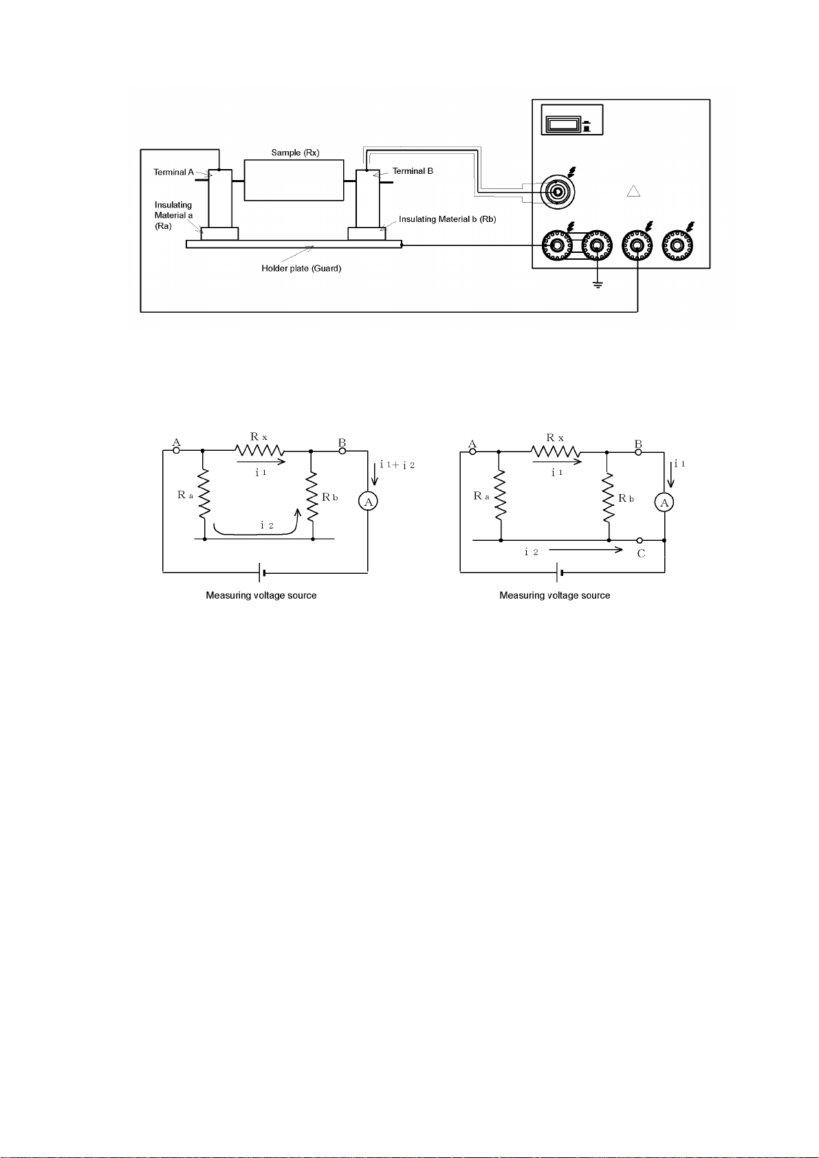
Fig. 6.3 Example of Holder with Guard
Fig. 6.4 Principle of guard
In measurement using a holder with a guard illustrated in Fig. 6.3 and considering the
flow of a current from Terminal A to Terminal B, one channel passes through Sample
(Rx), while the other channel flows to Terminal B passing through Insulating Material a
(Ra), the holder plate and Insulating Material b (Rb).
Starting measurement after connecting Terminal A to the “OUTPUT” terminal of this
meter and Terminal B to the “INPUT” terminal of the meter, currents that flow insulation
resistance (Rx) of the sample, as well as insulation resistances Ra and Rb of Insulating
Materials a and b, are collectively measured. This flow can be illustrated by the
equivalent circuit shown in Fig. 6.4 (a) without a guard.
The equivalent circuit shows that Current i
flowing through the sample and current i2 that
1
flows through Insulating Materials a and b both flow to the input circuit through the
Terminal B.
Next, using a meal plate for example as the holder plate of the holder and connecting it
to the “GUARD” terminal of the meter, the current flowing to the “INPUT” terminal will be
only the current that flows through the sample after the current that flows through
Insulating Materials a and b is eliminated. The equivalent circuit in this case is the
circuit in Fig. 6.4 (b) with a guard.
This equivalent circuit shows that Current i
that has passed through Insulating Materials
2
a flows directly to the common side of the current measuring unit without entering the
input circuit, to which only Current i
that has passed through the sample is input.
1
51
Page 62

Generally speaking, a guard is provided to a jig or a holder by connecting this guard
circuit to the “GUARD” terminal of the meter by making all currents that are not measured
to flow a guard circuit.
6.2.2 Auto measurement
Auto measurement, in which a jig or a terminal to be measured is automatically changed,
facilitates measurement when there are many parts to be measured or there are many
points of measurement.
When measuring samples by changing samples, jigs or terminals to be measured, a
change must be must be made tuned to timing of meter operation by the following two
methods.
(a) Change the sample or the jig tuned to the “/INDEX” signal output from the
“HANDLER” connector on the rear panel of the meter.
In this event, the meter should be set to the Internal Trigger mode or Manual Trigger
mode and measurement is started by the Internal Trigger mode or Manual Trigger.
In the Internal Trigger mode, averaging setting to average measured results can be
set.
(b) Output a trigger pulse on timing to change a sample and input the pulse to the “EXT
TRIGGER” connector or the “HANDLER” connector on the rear panel of the meter.
In this event, the meter should be set to the External Trigger mode and
measurement is started tuned to a trigger pulse that is input to the “EXT TRIGGER”
connector or the “HANDLER” connector on the rear panel of the meter.
Note:
See 9. “External Interfaces” for more information on output of a synchronous pulse and
input of an external trigger pulse.
See 5.1.7 “Setting averaging function” and 5.1.8 “Setting Trigger mode” for setting of the
averaging function and trigger mode respectively.
[Notice]
The [START] key outputs measuring voltage to ready a trigger. Pressing the
[START] key while the trigger mode is “INT” starts measurement. Note that
measurement is started by the [MAN. T] key or trigger input to “EXT TRIGGER”
input when the trigger mode is “MAN” or “EXT.”
[Notice]
The following conditions are needed for an external trigger signal:
Pulse width 100μs or more
Signal logic Negative logic (active low)
Drive output Open collector or TTL output
Drive current Sync current of more than 1mA
52
Page 63

[Caution]
When changing the measuring terminal by a relay while outputting measuring
voltage, serially insert a protective resistance to limit the current passing
through the contact to not exceed the maximum permissible current of the
contact, for protection of the relay contact.
Protective resistance value ≥(measuring voltage)/(maximum permissible current)
The meter is equipped with a contact check function that checks connection (contact) of
the sample and measuring circuit including a jig and other devices to enhance reliability
of insulation resistance measurement of samples with a large electrostatic capacity such
as capacitors. For more information, refer to 6.7.2 “Contact check.”
Measuring time can be shortened and measurement accuracy can be enhanced by taking
measurement after charging a sample in advance when automatically measuring a
sample of a large electrostatic capacity such as a capacitor.
The “CHARGE” terminal is provided for this purpose.
When using the “CHARGE” terminal, setting on the Setting screen is needed.
Press [SETUP] [F5] (POWR) to set the “POWER SOURCE SELECT” screen, set 10mA or
50mA as a current limiter set value “CURL :” and set “ON” in charge voltage output
terminal setting “CURL C:” Setting to ON lights up a side mark at “CHARGE ON” on the
left of the screen.
In this case, fix the current limiter on the “INPUT” terminal side to 5mA irrespective of the
setting of “CURL :” outputting a charging current of 5mA or 45mA is output to the
“CHARGE” terminal.
Connect the “CHARGE” terminal as exemplified in Fig. 6.5.
Rc is a sample measured after Rx
Fig. 6.5 Connection of CHARGE terminal (Grounding sample)
53
Page 64

6.2.3 When measuring jig is not used
When making measurement without using a jig or other means, use a measuring lead
with a test rod or a measuring lead with an alligator clip as an option and connect it to
the part to be measured.
Both of the measuring leads that are connected to the “OUTPUT” terminal have no guard,
while the measuring lead connected to the “INPUT” terminal has a guard. The
measuring lead with a test rod has a guard including a test rod so that measurement can
be performed by holding the test rod by hand. The alligator clip of the measuring lead
with an alligator clip is not guarded. Connect it to a terminal of the sample and measure
the sample with a hand off.
Connect the terminals on the panels and handle the meter by the same method as that
when a jig is used.
[Tip] Resistance values of insulation resistance naturally vary depending on the
insulating material. Impacts by measuring voltage, temperature and measuring
time are not small.
Typically, insulating materials are complex circuits with resistances and
electrostatic capacities that are connected serially and in parallel. Therefore,
impressing voltage to an insulating material, a dielectric absorption current and
leakage current corresponding to a charging current flow.
Insulation resistance is calculated by measuring this leakage current and
converting it into a resistance value. Generally, a dielectric absorption current is
substantially large compared with a leakage current and time constant of it is very
large depending on the type of insulating material so that a long time is needed till
a dielectric absorption current becomes smaller than a leakage current. When
insulation resistance is measured using such insulating material as a sample,
insulation resistance is low in measurement for a short time, becoming high longer
the measuring time is. The time constant and insulation resistance of a dielectric
absorption current vary significantly depending on the voltage impressed to the
insulating material. In general, insulation resistance lowers higher the measuring
voltage is.
Temperature also affects greatly. The type of insulating material also makes a
difference, but insulation resistance generally lowers higher the temperature is.
Correct measurement of insulation resistance is time consuming and is also
difficult.
Depending on the withstand voltage of a sample, measuring voltage sometimes
cannot be decided freely. Values obtained in one minute as measuring time are
used as measuring time and one-mute values of insulation resistance are used by
adding measuring voltage such as “DC 500V 1000MΩ.
When comparing insulation resistances, measurement must be made after
deciding measuring voltage and measuring time. It is sometimes important to
shorten measuring time (or inspection time) of parts and other samples. In this
case, it is important to measure after deciding a time within a range in which
correlation can be taken with a one-minute value.
54
Page 65

6.2.4 Measurement of circuits
The circuit is a combination of plural parts. Insulation resistance is measured outside of
circuits such as between circuits that are mutually insulated and between a circuit and
casing. The measuring method and handling of this meter are the same as those used
in measurement of insulation resistance of parts.
Normally, measuring voltage higher than voltage that is used inside the circuit is used in
measurements of insulation resistances of circuits. Measurement must be made
exercising reasonable caution so as not to affect circuits such as measuring voltage and
polarity.
When measuring samples such as a telephone cable that has many points of
measurement, it is effective to measure utilizing features of this meter, such as
measuring by automatically changing measurement points and making measuring
conditions identical.
6.3 Measuring Planar Sam ple
When measuring insulation resistance of a sample that has no terminals, devices that act
as terminals must be installed on the sample in one form or the other.
Devices of various shapes that act as terminals can be considered. Convenience with
which to easily exchange samples is desirable and devices of a structure that become
terminals only by contacting a sample are used more.
Terminals for measurement must be free of malcontact and must contact the sample
tightly. However, the shape and structure of the terminal differ depending on the
sample shape and property. Various methods to measure insulation resistance are used
with solid-state insulating materials by having a terminal (electrode) with a smooth and
flat surface contact a sample of a pin type with a specified shape or smooth and flat
surface so that contact can be made tightly without a gap.
This section describes these measuring methods.
6.3.1 Measurement by pin terminal
Insulation resistance is divided into “volume resistivity” caused by a current that flows
inside a sample and “surface resistivity” caused by a current that runs the surfaces of a
sample. Insulation resistance measurement is measurement of volume and surface
resistivities.
For example, a measuring terminal is made using a planar sample, by drilling two holes
of a specified diameter, such as tapered holes, at a predetermined spacing, and by
inserting pins coated with a material with relatively low insulation resistance such as
vaseline.
The surfaces of samples do not have to be finished into smooth surfaces and these
terminals can achieve relatively stable contact with a simple structure.
Set the measuring mode to “resistance measurement.”
55
Page 66

6.3.2 Measurement by electrode for surface resistance measurement
This electrode is used as a measuring terminal by pressing it onto a surface of the
sample. It can be used simply when a sample is relatively soft.
Strictly speaking, this electrode does not separate volume resistivity strictly. However,
in general, surface resistance is lower and can be measured in practice. It is especially
convenient in measuring samples whose surfaces are treated for prevention of
electrostatic resistance.
Set the measuring mode to “resistance measurement.”
6.3.3 Measurement by electrode for planar sample
Insulation resistance is divided into volume resistance and surface resistance and
characters of them are different. Therefore, volume resistance and surface resistance
must be measured separately.
When insulation resistances of insulating materials are mutually compared, insulation
resistances unique to insulating materials that are not affected by terminal shape or other
factors are needed. These are volume resistivity and surface resistivity and must be
converted by multiplying volume resistance and surface resistance, which are separately
measured, by a constant determined by the dimensions of an electrode used or other
parameters.
(1) Volume resistivity and surface resistivity
An example of electrode to measure volume resistance and surface resistance
and of usage are illustrated in Fig. 6.5.
Usages of electrodes suiting
measurement objects are as
follows.
A
Sample
B
d2
d1
t The main electrode is connected to
Fig. 6.5 Example of Planar Sample Electrode
Volume
resistance
A Main
electrode
B Guard
electrode
C Pair
electrode
the “INPUT” terminal, while the
guard electrode is connected to the
“GUARD” terminal and pair
electrode is connected to the
“OUTPUT” terminal.
Surface
resistance
Main
electrode
Pair
electrode
Guard
electrode
56
Page 67

Volume resistance and surface resistance measured and multiplied by an electrode
constant are called volume resistivity (ρ
) and surface resistivity (ρs), respectively.
v
2
Measured value
Volume resistivity ρ
Π · D1
= ×
v
4t 10
where ρ
Π
D
t
: volume resistivity in [Ω·cm]
v
: circle ratio = 3.14
: diameter of main electrode in [mm]
: Sample thickness in [mm]
Π · (D2+D1)
Surface resistivity ρ
= × Measured value
s
D2-D1
where ρ
Π
D
: surface resistivity in [Ω]
s
: circle ratio = 3.14
: diameter of main electrode in [mm]
(2) Electrode constant setting
Measure volume resistivity and surface resistivity by setting measuring modes
for volume resistivity measurement and surface resistivity measurement
respectively referring to 5.1.2 “Setting measuring mode.”
The meter is capable of automatically performing calculations of volume
resistivity and surface resistivity mentioned in 1). For this purpose, set in
advance constants of electrodes to be used in measurement as follows.
The following three electrode constants are set:
D1 (IN DIAMETER): Set diameter of the main electrode (A) in increments of mm.
D2 (OUT DIAMETER): Set inside diameter of the pair electrode (B) in
increments of mm.
t (THICKNESS): Set thickness of the sample in increments of mm.
Set the desired electrode constants on the screen illustrated in Fig. 6.6.
On the measurement screen, measured volume resistivity and surface resistivity
are indicated by “Rv” and “Rs” respectively.
Press the [ELEC] (SET ELEC
TRODE SIZE) key on the measurement screen.
The screen will change to a screen for setting electrode constants to be used in
measurement of volume and surface resistivities. (See Fig. 6.6)
57
Page 68

ELECTRODE SIZE
D1(IN DIAMETER): [ 26.0]mm
D2(OUT DIAMETER):[ 38.0]mm
t (THICKNESS ):[ 0.100]mm
DOWN UP ACTL
Fig. 6.6 Electrode Constant Setting Screen (Disc Electrode)
On the screen illustrated in Fig. 6.6, the function keys [F2], [F3] and [F5] will change to
DOWN, UP and ACTL respectively. The [F2] DOWN and [F3] UP keys are used for
selecting the constants preset in the meter. When setting a value other than specified
values, select the item desired to set by operating the [▲] and [▼] keys and input the
value by keying the numeric keys.
(3) Specified value of electrode constant
The meter has the following values as specified values.
D1, D2 Specified value of
electrode diameter
If D1 = 26, D2 = 38
If D1 = 50, D2 = 70
If D1 = 70, D2 = 90
If D1 = 76, D2 = 88
Press the [ENTER] key after finishing setting. The screen will return to the
measurement screen. Select “surface resistivity measurement” or “volume resistivity
measurement” as the measuring mode by pressing the F2 [MODE] key.
6.3.4 Use of shielding box
In measurement of high insulation resistance, stable measurement is sometimes
hampered due to noise and induced current in the ambience as measurement is
high-sensitivity measurement of a current.
Samples need be placed in a shielding box when measuring samples of high insulation
resistance.
(1) Connection
An example of connection when a shielding box is used is illustrated in Fig. 6.7.
t Specified value of sample
thickness
t=0.010 t= 2.000
t=0.100 t= 5.000
t=0.200 t=10.000
t=0.500 t=20.000
t=1.000 t=30.000
58
Page 69

Fig. 6.7 Example of shielding box connection
[Warning]
Maximum 1000V of measuring voltage is output between the “GROUND””
terminal and “GUARD” terminal or the “OUTPUT” terminal depending on the
connecting method of the short bar.
Be sure to connect the outer casing of the shielding box to the “GROUND”
terminal.
Use the interlock function to prevent an electric accident.
Exercise reasonable care with an electric shock.
[Note]
As an option, a shielding box model SME-8350 is available.
Set the measuring mode in accordance with the measuring object as explained in 6.2
“Measuring Parts and Circuits” and 6.3 “Measuring Planar Sample” when a shielding box
is used.
(2) Interlock function setting
Output of measuring voltage is sometimes not safe such as when the lid of a
shielding box is opened. The INTERLOCK function is useful in these cases.
As in the example of use of a shielding box illustrated in Fig. 6.7, connect the
“open” signal of the shielding box lid to the [INTERLOCK] connector in the rear
of the meter through the interlock connection cable. Then set as follows.
Press the [F1] CONF (CONF
Setting screen. (See Fig. 5.6)
The screen will change to the External Interface Condition Setting screen. (Fig.
6.8)
The External Interface Condition Setting screen is split into two pages.
IGURATION) key in the Operating Environment
59
Page 70

CONFIGURATION PAGE-1/2
INTERLOCK:CONECT/CUTOFF
BEEP :OFF/O N
BEEP :NO/GO
CLICK :OFF/O N
PAGE
Fig. 6.8 External Interface Condition Setting Screen 1/2
Select “PAGE-1/2” and set an item in “INTERLOCK:.” The following function
will be displayed.
CONECT: The interlock function will be enabled.
Short-circuiting the “INTERLOCK” input on the rear (low level input) enables
output of measuring voltage, disabling output of measuring voltage when the
“INTERLOCK” input is open-circuited (high level input).
When disabled, the [START] key cannot be operated and a side mark (“◂ ”) will
light up by “INTERLOCK” indication on the left of the LCD screen.
CUTOFF: The interlock function will be disabled.
Measuring voltage can always be output irrespective of the “INTERLOCK” input
on the rear.
6.4 Measuring Liquid Sample
Measure volume resistance of a liquid sample by dipping electrodes of a preset shape in
the liquid sample or use an electrode that also acts as a container of the liquid sample.
6.4.1 Measurement by electrode for liquid sample
(1) Connection
A sketch of liquid sample electrodes and a connection example of them are
illustrated in Fig. 6.9.
Fig. 6.9 Connection Example of Liquid Sample Electrodes
60
Page 71

(2) Electrode constant setting
To set resistance values that are not affected by the electrode shape, set in this
meter the electrode constants used in measurement and measure resistance as
volume resistivity of a liquid sample.
[Note] Refer to the instruction manual of the liquid sample electrode for more information
about electrode constants. The volume resistivity is calculated by multiplying a
measured value by an electrode constant as follows.
Volume resistivity ρv = K·measured value [Ω·cm]
Where ρv : volume resistivity in [Ω·cm]
K : electrode constant in [cm]
The meter is capable of automatically calculating volume resistivity.
Set an electrode constant as follows.
On the screen illustrated in Fig. 6.6, press the [F5] ACTL key.
The screen will change to the Electrode Constant Setting screen illustrated in Fig. 6.10.
Input the electrode constant of the electrode to be used.
Press the [ENTER] key after finishing setting.
The screen will return to the measurement screen. Select “volume resistivity” [Rv] by
pressing the F2 [MODE] key as the measuring mode. (Displayed measured values will
be the same values as those of [Rv] values even when [Rs] is selected.)
ACTUAL COEFFICIENT
K:[ 0.01]
SIZE
Fig. 6.10 Electrode Constant Setting Screen
[Note]
Press the [ENTER] key to use constants on the screen set before returning to the
measurement screen. The concept of electrode constant setting explained in 6.3.3 2)
“Electrode constant setting” and 6.4 “Measuring Liquid Sample” is illustrated below.
61
Page 72

Measured
value display
screen
[E LEC]
Setting Screen
Setting planar
sample electrode
[SIZE]
[ACTL]
Setting liquid
sample electrode
[ENTER]
(D1,D2,t)
[E NTER]
Planar sample
measuring mode
Fig. 6.11 Concept of Electrode Constant Setting
6.5 Current Measurement
Set the measuring mode to “Current Measurement” referring to 5.1.2 “Setting measuring
mode” when measuring a current.
(1) Connection
When the measuring power source of the meter is used, connect measuring
object such as a part and circuit between the “OUTPUT” terminal and “INPUT”
terminal on the panel of the meter as in measurement of insulation resistance.
The polarities of the “OUTPUT” terminal and “INPUT” terminal are “+” and “-”
respectively. Connect the terminals matching the polarities of the work. Be
sue to use a shielded-conductor cable as the measuring lead connected to the
“INPUT” terminal to prevent induced troubles such as noise and connect the
shielded conductor to the “GUARD” terminal.
Connect the “+” side of the work to the “INPUT” terminal and “-” side to the
“GUARD” terminal when connecting to a work that generates a current.
In this case also, be sure to use a shielded-conductor cable as the
measuring lead connected to the “INPUT” terminal and connect the shielded
conductor to the “GUARD” terminal.
6.6 Ending Measurement
Press the [STOP] key when finishing measurement.
Pressing the [STOP] key lights up the [STOP] lamp beside the key. The measuring
voltage output will become 0V and trigger input will be prohibited in a [STOP] state.
The circuit between the “OUTPUT” terminal and “INPUT” terminal will become a
discharge state (discharge state with a current limiter connected). The state of the
“CHARGE” terminal will also become the same state.
62
Page 73

[Warning]
Residual measuring voltage sometimes still remains inside the sample after
pressing the [STOP] key. Be c autious and do not touch metal parts
impressed with voltage till the inside of the meter is thoroughly discharged.
Otherwise an electric shock may result.
6.7 Measurement Check
The meter is capable of checking “acceptable” or “non-acceptable” of a measured state
as explained below.
6.7.1 Voltage check
The voltage check function checks output state of measuring voltage and determines if
measuring voltage is output normally. The voltage check accuracy is ±3% and the
setting accuracy of measuring voltage cannot be checked. The voltage check function
is mainly used in detecting flaws of the voltage output circuit and operational state of
current limiters.
If the measuring voltage is below 10V, correct decisions sometimes cannot be made due
to voltage check accuracy problems. Use this function when the measuring voltage is
higher than 10V.
Voltage checks can be made for each measurement and only when necessary by
operating the panel keys or by issuing commands through interfaces.
[Notice]
Measurement and data output will be made as in normal operation even if a
decision of voltage check is <NG>. However, signals will not be saved in
the data buffer if the result of a voltage check is <NG>.
(1) Setting automatic voltage check
Press [SHIFT] [F3] V.CK on the setting screen referring to 4.5 “Display Screen”
and
5.1.1 “Screen types.” Select on the screen whether to (execute · not execute)
monitoring of the measuring voltage automatically.
Selection made for voltage checks will be indicated by a side mark.
The side mark will flash in case the result of a voltage check is not acceptable.
6.7.2 Contact check
Capacitors with defective insulation are judged “acceptable” in capacitor measurement if
measurement is made while the measuring jig of the measuring system is not contacting
a capacitor. To prevent these errors, this function checks whether or not the measuring
jig is contacting a capacitor. This function is one of the features of the meter.
The side mark flickers (a sample is not connected) when the capacity of the measuring
system becomes smaller than the reference value for contact check. Check the meter
and measuring jig.
63
Page 74

Detection is made by detecting the electrostatic capacity and this function cannot be
used with samples whose electrostatic capacity component is small such as pure
resistance.
The cable length is predetermined because an electrostatic capacity of the measuring
cable enters the jig capacity in parallel. The measuring cable length was adjusted to 1m
during a preshipment inspection at the factory. Readjustment will be necessary if a
longer cable is required. However, the maximum cable length guaranteed for detection
accuracy is 2m. The cable length can be lengthened up to about 4m if the electrostatic
capacity of a sample is several thousand pF or higher. Nevertheless, the jig capacity
offset capacity will deteriorate and errors of more than 50% will result. (Errors are
±20% or less if the cable length is 1m)
Contact checks are made in an auto execute mode, in which checks are made for each
measurement, and in a single execute mode in which checks are made by keying the
panel keys or by interface commands when needed.
(1) Setting auto contact check execute
Press [SHIFT] [F4] C.CK on the setting screen referring to 4.5 “Display Screen”
and
5.1.1 “Screen types.” Select on the screen whether to (execute · not execute)
contact check during measurement.
Selection made for contact checks will be indicated by a side mark.
The side mark will flash in case the result of a voltage check is not acceptable.
[Notice]
Measurement and data output will be made as normal even if a decision of
contact check is <NG>. However, signals will not be saved in the data
buffer if the result of a contact check is <NG>.
[Notice]
Be certain to set an open correction value when using the contact check
function. Otherwise errors will result. A side mark (“◄”) will be lit in the
“OPEN SET” window in the lower left of the front panel when open correction
is executed once.
[Warning]
In open correction, measuring voltage is momentarily output to the
measuring terminal. Carefully check that no hand or other body part is
contacting the jig or measuring circuit before pressing the [OPEN] key.
Maximum 1000V voltage is output and an electric shock is a hazardous
possibility.
(2) Open correction value setting
Set a decision capacity in contact check when setting an open correction value.
Press the [OPEN] (SET OPEN
screen. The screen will change to the screen to set a reference value for
contact check. (See Fig. 6.12)
CHECK PARAMETER) key on the measurement
64
Page 75

OPEN OFFSET VALUE
OPEN= 2.5pF work:[ 0.5]pF
RTRY
Fig. 6.12 Open Correction Value Setting Screen
Displaying this screen, the open capacity of the measurement system will be measured
and the following data will be displayed:
OPEN = x.xpF work
The function key [F5] will change to the RTRY (R
RTRY key will redo measurement of the open capacity value of the measuring system.
(3 Setting decision capacity reference value
A minimum capacity value of a sample is set operating the numeric keys. (0.5
to 99.9)
The minimum capacity value is 1/10 the open capacity value of the measured
measuring system or 0.5pF, whichever is larger.
The reference value for contact checks is a total of the open capacity value of
the measured measuring system and of a 1/2 value of the set capacity value.
Contact NG will result if the capacity is smaller than this value.
ETRY) function. Pressing the [F5]
65
Page 76

7. GP-IB Interface
7.1 Overview
The DSM-8104 is equipped with a GP-IB interface as a communication function among
its standard provisions. This interface allows remote control and transfer of data by a
GP-IB controller. See 5.1.12 “Setting other items” for setting of GP-IB addresses.
7.2 Specification
Electrical/mechanical : Conform to IEEE std. 488-1978
Code : ASCII code
Address setting : Talker/listener addresses 0 to 30 can be set.
Remote status cancel : Cancelled by pressing [LOCAL] key on the panel
Function Description
SH1 (Source handshake) All functions
AH1 (Acceptor handshake) All functions
T6 (Talker)
L48 (Listener)
SR1 (Service·request) All functions
RL1 (Remote·local) All functions
PPO (Parallel·polling) No function
DC1 (Bus·buffer) All functions
DT1 (Device·clear) All functions
CO (Controller) No function
E2 (Bus·buffer) Tri-state output
Table 7.1 Interface Functions
Basic talker function
Serial polling function
Talker cancel by listener specification
(MLA)
Basic listener function
Listener cancel by talker designation
(MTA)
66
Page 77

7.3 Talker Function
Output data format
The output format of measured data can be selected from the following four types by the
“DFM” command.
(1) Basic format
±d.ddddE±dd
,d ,d
L
<EOI>
F
① ② ③ ④
① Measured value
Measured values will be set in an 11-byte exponential format.
±d.ddddE±dd d: numeral
Output data in overrange will set “0s” in all numerals for resistance
measurement and “9s” in all numerals for current measurement.
+0.0000E+00
+9.9999E+99
Resistance measurement
Current measurement
② Status
Results of voltage checks, contact checks and overrange will be set in
numerals 0 to 4.
Individual results will be allocated to bit0 to bit2 in status and logical OR of
them will be output.
bit0: Voltage check NG (Result of auto execution)
bit1: Contact check NG (Result of auto execution)
bit2: Overrange
If status is “0,” results are normal in all events.
③ Comparison result
0: HI (Measured value exceeded upper-limit reference value)
1: IN (Measured value remains within the range of upper- and lower-limit
reference values)
2: LO (Measured value is less than lower-limit reference value)
[Note] When comparison measurement is off, the comparison result will
not be added.
④ Delimiter
An output message delimiter can be designated from the following three
delimiters by the “DLM” command.
L
<EOI> Default
F
CRL
<EOI>
F
<EOI>
[Note] A default will result when the power is turned on.
(2) Format with measured value only
Status and data of comparison result will not be added.
The other details are the same as those for the basic format.
67
Page 78

(3) Format with comparison result only
L
d
<EOI>
F
① ②
① Comparison result
The details are the same as those for the basic format.
② Delimiter
The details are the same as those for the basic format.
(4) No data return
Specifying this format will return data as a trigger response. This format is
used for storing data in the data buffer temporarily and reading it in batch.
Data separator
Two data fields are separated by one comma “,.”
7.4 Response to Query Program Message
Responses to query program messages are made in the following formats: NR1, NR2,
NR3, any ASCII character string format and binary format with a specified length. See
Table 7.3 List of Program Messages when deciding which format will be used.
NR1 format
Data strings: Integers (Mainly setting type and status)
NR1 format
Data strings: Integers (Mainly setting type and status)
L
-ddddd
<EOI>
F
NR2 format
Data strings: Number of fixed decimal points (Mainly set values)
L
-ddd.d
<EOI>
F
NR3 format
Data strings: Number of floating decimal points (Mainly set and measured values)
L
±d.ddddE±dd
<EOI>
F
ASCII character string format
Data strings: Random ASCII character strings (Mainly equipment IDs)
XXXXXXXXXXX
<EOI>
F
“X” denotes an ASCII character
L
Binary format with a specified length (Used in data buffer readout)
#
4 nnnn bbbbb・・・・
L
<EOI>
F
① ② ③ ④ ⑤
① Indicates binary format.
68
Page 79

② Indicates the number of “n” columns that follow. Fixed to “4.”
③ A 4-digit numeric value indicating the number of bytes of binary data that
follows.
④ Binary data.
⑤ Delimiter.
The data format is the 32bit floating decimal point format conforming to
IEEE 754. In case of overrange, all bits in both exponent part and
fixed-point part become “1s.” (Nonnumeric)
Message delimiter
An output message delimiter can be designated from among the following
three delimiters by the “DLM” command.
L
<EOI> Default
F
CRL
<EOI>
F
<EOI>
[Note] A default will result when the power is turned on.
7.5 Listener Function
The DSM-8104 accepts program messages in ASCII character strings.
In this manual, program messages are also described generically as “commands” or
“command messages.”
Program messages are classified as follows.
Table 7.2 Classification of Program Messages
Program message
Command program message
Header only
Header + data
Query program message
Header only
Command program message
Command program messages are used in setting equipment, measurement start and for
other purposes.
Query program message
69
Page 80

Query program messages are used when querying about equipment status and for other
purposes.
Program message composition
① A header only
② A header and one data group separated by a header separator.
③ Plural data groups separated by data separators.
④ Plural data groups separated by message separators.
① XXX<Delimiter>
② XXX dddddd<Delimiter>
③ XXX ddd,ddd,ddd,ddd<Delimiter>
④ XXX ddd;XXX ddd<Delimiter>
Separator
The separators use the following characters.
① Header separator------( ) space
② Data separator ------(,) comma
③ Message separator ----(;) semicolon
Message delimiter
The following six delimiters are accepted as effective input message delimiters:
②
②
②
CRL
L
C
<EOI> ---CR + LF <EOI> simultaneously with LF
F
<EOI> ----LF <EOI> simultaneously with LF
F
<EOI> ----CR <EOI> simultaneously with CR
R
② <EOI> -----<EOI> simultaneously with last data byte
②
①
CRL
L
---------
F
----------
F
C
L
F
+
R
L
F
Format of command program message
Commands with plural program data groups can omit program data by using formats of
the following examples. These commands can be used with program data that requires
no alterations.
Example 1: Altering only sequence program No.
Example 2: Altering Sequence Discharge 2
Example 3: Shutting down a sequence
7.6 Device Clear Function
The DCL and SDC commands clear the input buffer and output queues. If in a start
state (voltage being output, during measurement), the commands process stopping.
7.7 Device Trigger Function
The GET command performs the same function as that of the *TRG command message.
70
Page 81

7.8 Remote and Local Functions
In the Remote mode, the panel keys are disabled except the [LOCAL], [STOP] and
[LCDOF] keys. Press the [LOCAL] key to return to the Local mode.
The [LOCAL] key is also disabled when the Local Lockout (LLO) command is executed by
an interface.
The [STOP] key and [LCDOF] key can be used even in the local lockout state.
71
Page 82

Syntax Chart
Fig. 7.1 Message Syntax Chart
72
Page 83

Command program header
Fig. 7.2 Program Header Syntax Chart
73
Page 84

NRf format
Fig. 7.3 Syntax Chart of Data Part
74
Page 85

7.9 Program Messages
7.9.1 List of program messages
Table 7.3 Setting Control Program Messages 1/10
Mnemonic Description Format
DLM Delimiter designation in talker mode
d1 (Delimiter designation: 0 ~ 2)
0: LF<EOI> Default
1: CRLF<EOI>
2: <EOI>
Returns to default when power is turned on.
DLM?
Delimiter query
[Format]
DLM d1
d1: NR1 format
[Format]
Response is similar to setting.
DFM
DFM? Query response in output data format
MOD
Output data format designation
d1 (Format designation: 0 ~ 3)
0: Basic format Default
1: Measured values only output
2: Comparison results only output
3: No data output
Returns to default when power is turned on.
designation is same as setting.
Measuring mode setting
DLM?
[Response]
d1
[Format]
DFM d1
d1: NR1 format
[Format]
DFM?
[Response]
d1
[Format]
d1 (Mode: 0 ~ 3)
0: Resistance measuring mode
1: Current measuring mode
2: Surface resistivity measuring mode
3: Volume resistivity measuring mode
MOD? Query response in measuring mode is same as
setting.
75
MOD d1
d1: NR1 format
[Format]
MOD?
[Response]
d1
Page 86

Table 7.3 Setting Control Program Messages 2/10
Mnemonic Description Format
MON Changeover between regular measurement
screen and sequence monitoring screen
d1 (Screen designation: 0 ~ 1)
0: Regular measurement screen
1: Sequence monitoring screen
MON? Query response in screen state is same as
setting.
LCD LCD display mode setting
d1 (Display mode: 0 ~ 1)
0: OFF Lamp extinguished
1: ON Lamp lit
Corresponds to [LCDOF] key.
LCD? Query response in LCD display mode is same as
setting.
FIG Setting number of effective columns for
measured value display
d1 (Effective columns: 2 ~ 5)
FIG? Query response on setting number of effective
columns for measured value display is same as
setting.
DSP
DSP? Query response in display mode is same as
Display mode setting
d1 (0 ~ 1)
0: Exponent display
1: Unit symbol display
setting.
[Format]
MON d1
d1: NR1 format
[Format]
MON?
[Response]
d1
Format]
DCD d1
d1: NR1 format
[Format]
LCD?
[Response]
d1
[Format]
FIG d1
d1: NR1 format
[Format]
FIG?
[Response]
d1
[Format]
DSP d1
d1: NR1 format
[Format]
DSP?
[Response]
d1
76
Page 87

Table 7.3 Setting Control Program Messages 3/10
Mnemonic Description Format
DLY Trigger delay time (ms) setting
d1 (Time: 0 ~ 9999)
DLY? Query response on trigger delay time is same as
setting.
AVE
AVE? Query response in averaging is same as setting. [Format]
SPL Integral time setting (Unit, set values)
SPL? Query response on setting number of integral
RNG Current range setting
Averaging setting
d1 (Selection: 0 ~ 1)
0: OFF (Not done)
1: ON (Done)
d1 (Unit: 0 ~ 1)
0: PLC
1: ms
d2 (Set value)
PLC: 1 ~ 15
ms: 2 ~ 300
time (unit, set value) is same as setting.
d1 (AUTO/HOLD Selection: 0 ~ 1)
0: HOLD
1: AUTO
d2 (Range during HOLD: 0 ~ 7)
0: 10μF(Range 1) 4: 1nF(Range 5)
1: 1μF(Range 2) 5: 100pF(Range 6)
2: 100nF(Range 3) 6: 10pF(Range 7)
3: 10nF(Range 4) 7: 10pF(Range 8)
Capacity of integrating capacity is set in range
changeover
[Format]
DLY d1
d1: NR1 format
[Format]
DLY?
[Response]
d1
[Format]
AVE d1
d1: NR1 format
AVE?
[Response]
d1
[Format]
SPL d1, d2
d1: NR1 format
d2: NR1 format
[Format]
SPL?
[Response]
d1, d2
[Format]
RNG d1, d2
d1: NR1 format
d2: NR1 format
RNG? Query response on current range is same as
setting.
77
[Format]
RNG?
[Response]
d1, d2
Page 88

Table 7.3 Setting Control Program Messages 4/10
Mnemonic Description Format
SRT Function to interact with measuring voltage ON
or measurement start [START] key.
STP Function to interact with measuring stop
(measuring voltage OFF) [STOP] key.
MTG Generates manual trigger.
Enabled when trigger mode is manual or
external.
IVS Measuring voltage setting
d1 (Voltage: 0.1 ~ 1000.0)V
IVS? Query response of measuring voltage is same as
setting.
PWS Measuring power source setting
d1 (Total current limit value: 0 ~ 2)
0: 5mA 1: 10mA 2:
50mA
d2 (Charge output setting: 0 ~ 1)
0: OFF 1: ON
d3 (Noise filter: 0 ~ 1)
0: OFF (Fast changeover mode)
1: ON (Low noise mode)
PWS? Query response on measuring power source
setting is same as setting.
[Format]
SRT
[Format]
STP
[Format]
MTG
[Format]
IVS d1
d1: NR2 format
11 [Format]
IVS?
[Response]
d1
[Format]
PWS d1, d2, d3
d1: NR1 format
d2: NR1 format
d3: NR1 format
[Format]
PWS?
[Response]
d1, d2, d3
78
Page 89

Table 7.3 Setting Control Program Messages 5/10
Mnemonic Description Format
DEV Deviation value display mode setting
d1 (Mode: 0 ~ 2)
0: OFF
1: DEV
2: PAR
d2 (Reference deviation value)
(-9.999E+30 ~ 9.999E+30)
[Note] Mode: d2 is enabled even when OFF.
(Retained as current set value)
DEV? Query response in deviation value display mode
is same as setting.
ELC Electrode data setting
d1 (SIZE/ACTL selection)
(0: ACTUAL, 1:SIZE)
d2 (Electrode inside diameter SIZE)
(0.0 ~ 999.9mm)
d3 (Electrode outside diameter SIZE)
(0.1 ~ 1199.9mm)
d4 (Sample thickness SIZE)
(0.001 ~ 30.000mm)
d5 (Random coefficient ACTUAL)
(0.01 ~ 999.99mm)
[Note] Be sure to achieve (Electrode inside
diameter < Electrode outside diameter).
Ignored if not complied with and only
settable parts are set.
ELC? Query response electrode data is same as
setting.
[Format]
DEV d1, d2
d1: NR1 format
d2: NR3 format
Format]
DEV?
[Response]
d1, d2
Format]
ELC d1, d2, d3, d4, d5
d1: NR1 format
d2: NR2 format
d3: NR2 format
d4: NR2 format
d5: NR2 format
[Format]
ELC?
[Response]
d1, d2, d3, d4, d5
79
Page 90

Table 7.3 Setting Control Program Messages 6/10
Mnemonic Description Format
VCM Selection of auto voltage check execute mode
d1 (Select: 0 ~ 1)
0: OFF
1: ON
VCM? Query response of auto voltage monitoring
execute mode is same as setting.
CCM Selection of auto contact check execute mode
d1 (Select: 0 ~ 1)
0: OFF
1: ON
CCM? Query response of auto contact check execute
mode is same as setting.
WCP
WCP? Query response of work capacity is same as
OST?
Work capacity setting
Capacity of work for open correction value
calculation
d1 (0.5 ~ 99.9) pF
setting.
Executes open correction once and capacity
value measured during open correction is
returned as a response.
In case of error, “999.9” is returned.
d1 (Jig capacity: 0 ~ 99.9)
In error: 999.9
[Note] Be sure to carry out open correction once
before performing a contact check.
[Format]
VCM d1
d1: NR1 format
[Format]
VCM?
[Response]
d1
[Format]
CCM d1
d1: NR1 format
[Format]
CCM?
[Response]
d1
[Format]
WCP d1
d1: NR2 format
[Format]
WCP?
[Response]
d1
[Format]
OST?
[Response]
d1: NR2 format
VCK? Executes voltage check once and returns result
of it as a response.
d1 (0 ~ 1)
0: NO 1: GO
CCK? Executes contact check once and returns result
of it as a response.
d1 (0 ~ 1)
0: NO 1: GO
80
[Format]
VCK?
[Response]
d1
[Format]
CCK?
[Response]
d1
Page 91

Table 7.3 Setting Control Program Messages 7/10
Mnemonic Description Format
TGM Trigger mode setting
d1 (Mode: 0 ~ 2)
0: Internal trigger
1: Manual trigger
2: External trigger
TGM? Query response of trigger mode is same as
setting.
RDT? Measured data query
d1 (Format designation: 0 ~ 2)
0: Basic format
1: Measured value only
2: Comparison result only
Most recent measured data is read out. This
command is used to read data when
measurement is made in the Internal Trigger
mode. Needs not be used in manual trigger,
external trigger and sequential measurement.
CMP Comparison Measuring mode setting
d1 (Comparison execute: 0 ~ 1)
0: OFF 1: ON
d2 (Mode: 0 ~ 2)
0: HI 1: IN 2: LO
d3 (Upper-limit comparison value)
(-9.999E+30 ~ 9.999E+30)
d4 (Lower-limit comparison value)
(-9.999E+30 ~ 9.999E+30)
[Note]
1. Must be (d3 > d4).
If not complied with, currently set value will be
used.
2. Comparison execute: d2, d3 and d4 are
enabled even when OFF.
(Retained as current set value)
[Format]
TGM d1
d1: NR1 format
[Format]
TGM?
[Response]
d1
[Format]
RDT? d1
d1: NR1 format
[Response]
(See 7.3)
[Format]
CMP d1, d2, d3, d4
d1: NR1 format
d2: NR1 format
d3: NR3 format
d4: NR3 format
CMP? Query response of Comparison Measuring mode
is same as setting.
81
[Format]
CMP?
[Response]
d1, d2, d3, d4
Page 92
Table 7.3 Setting Control Program Messages 8/10
Mnemonic Description Format
SEQ Sequential mode setting
d1 (Mode: 0 ~ 1)
0: OFF 1: ON
d2 (Program No.: 0 ~ 9)
No. of program executed when sequential mode
is turned ON
d3 (Discharging time before measurement)
(0.0 ~ 999.9s)
d4 (Charging time)
(0.0 ~ 999.9s)
d5 (Measuring time)
(0.0 ~ 999.9s)
d6 (Discharging time after measurement)
(0.0 ~ 999.9s)
[Note] Sequential mode: Subsequent parameters
are effective even on OFF.
(Retained as current set value)
SEQ? Same as set items of query SEQ command
message in sequential mode. Returns current
set data.
d1 (Mode: 0 ~ 1)
d2 (Program No.: 0 ~ 9)
d3 (Discharging time before measurement)
d4 (Charging time)
d5 (Measuring time)
d6 (Discharging time after measurement)
CNF Operation environment setting
d1 (Interlock control provided, not provided: 0 ~
1)
0: CONNECT 1: CUTOFF
d2 (Beep tone provided, not provided: 0 ~ 1)
0: OFF 1: ON
d3 (Beep tone good/no good: 0 ~ 1)
0: NO 1: GO
d4 (Click tone provided, not provided: 0 ~ 1)
0: OFF 1: ON
[Format]
SEQ d1
d2, d3, d4, d5, d6
d1: NR1 format
d2: NR1 format
d3: NR2 format
d4: NR2 format
d5: NR2 format
d6: NR2 format
[Format]
SEQ?
[Response]
[Format]
CNF d1, d2, d3, d4, d5
d1: NR1 format
d2: NR1 format
d3: NR1 format
d4: NR1 format
CNF? Query response of operation environment is
same as setting.
82
[Format]
CNF?
[Response]
d1, d2, d3, d4
Page 93

Table 7.3 Setting Control Program Messages 9/10
Mnemonic Description Format
THL Histogram display threshold setting
d1 ~ d9: Threshold 1 ~ threshold 9
[Note]
1. d1 to d9 are automatically sorted and can be
set sequence free. d1 > d2 is observed
relative to the screen.
2. Set “0s” where no settings are to be made
such as when setting of d1 to d9 entirely is not
required.
Example: “THL 1E12, 5E11, 1E11, 5E10, 0, 0,
0, 0, 0”
THL? Query response of threshold is same as setting. Format]
[Format]
THL d1, 2d, d3, d4, d5,
d6, d7, d8, d9
d1 ~ d9: NR3 format
THL?
[Response]
d1, 2d, d3, d4, d5,
d6, d7, d8, d9
RHS? Histogram counter readout
Returns count values of bar graphs divided into
ten and displayed on the screen as responses.
d1 to d2 are output in order of large threshold.
CHS Histogram counter clear
Corresponds to operation of [DATA] CLRH YES.
BSZ? Reads number of data groups in the measured
data buffer.
RBF? Measured data buffer readout
d1 (Format designation: 0 ~ 1)
0: ASCII format
1: Binary format
All data in the data buffer is output continually
beginning oldest data
CBF Measured data buffer clear
Corresponds to operation of [DATA] CLRD ALL
[Format]
RHS?
[Response]
d1 ~ d10: NR1 format
[Format]
CHS
Format]
BSZ?
[Response]
d1: NR1 format
[Format]
RBF? d1
[Response]
If ASCII
If binary
Binary response data
with length
specification
[Format]
CBF
83
Page 94

Table 7.3 Setting Control Program Messages 10/10
Mnemonic Description Format
ACL
ACL? Query response of auto self-calibration (current
Auto self-calibration (current range calibration)
setting
d1 (Auto self-calibration done and not done: 0 ~
1)
0: OFF
1: ON
d2 (Auto self-calibration interval time)
(10 ~ 9999s)
range calibration) is same as setting.
[Format]
ACL d1, d2
d1: NR1 format
d2: NR1 format
[Format]
ACL?
[Response]
d1, d2
84
Page 95
Table 7.4 Program Messages of Execution and Execution Result Acquisition 1/3
Mnemonic Description Format
ERR? Error information clear
d1 (Error information: 0 ~ 255)
See Table 7.7.
DSE Sets the device event status enable register.
d1 (0 ~ 255)
See Fig. 7.8.
[Format]
ERR?
[Response]
d1: NR1 format
[Format]
DSE d1
d1: NR1 format
DSE? Query response data of the device event status
enable register is same as setting.
DSR? Query about data of the device event status
enable register
d1 (0 ~ 255)
See Fig. 7.8 and Table 7.8.
[Note]
Data will be cleared simultaneously with
response output.
*SAV Environmental data save
d1 (Environmental data No.: 0 ~9)
*RCL Environmental data recall
d1 (Environmental data No.: 0 ~9)
*IDN? Equipment ID query
Returns equipment IDs of DSM as responses.
d1
(HIOKI, DSM8104, 0, version)
*CAL? Self-calibration (curren t range calibration)
execute
Executes self-calibration once and returns
results of it as response.
Response
d1 0: NG
1: OK
[Format]
DSE?
[Response]
d1: NR1 format
[Format]
DSR?
[Response]
d1: NR1 format
[Format]
*SAV d1
d1: NR1 format
[Format]
*RCL d1
d1: NR1 format
[Format]
*IDN?
[Response]
d1: Character string
[Format]
*CAL?
[Response]
d1: NR1 format
85
Page 96

Table 7.4
Program Messages of Execution and Execution Result Acquisition 2/3
Mnemonic Description Format
*TST? Self-diagno sis result query
Executes self-diagnosis once and returns result
of it as response.
d1 (Self diagnosis result: 0 ~ 1)
[Format]
*TST?
[Response]
d1: NR1 format
0: NG
1: OK
*TRG The same function as the GET message and
has the following functions.
[Format]
*TRG
When the measuring sequence is OFF, the
following operations are carried out in the
Trigger mode.
TRIG-INT: Ignored.
-MAN: Generates trigger once if in start
state.
-EXT: Same as in -MAN.
Measuring sequence is started if sequence ON.
*CLS Status register clear
See Fig. 7.5.
*SRE Sets the service request enable register.
d1 (0 ~ 255)
See Fig. 7.5 and Table 7.5.
*SRE? Query of data in the service request enable
register.
d1 (0 ~ 63, 128 ~ 191)
[Note]
[Format]
*CLS
[Format]
*SRE d1
d1: NR1 format
[Format]
*SRE
[Response]
d1: NR1 format
Bit 6 cannot be set in *SRE.
*STB? Query of data in the status byte register.
d1 (0 ~ 255)
See Table 7.5.
[Format]
*STB?
[Response]
d1: NR1 format
*ESE Sets the standard event status enable register.
d1 (0 ~ 255)
See Table 7.6.
*ESE? Query of data in the standard event status
enable register.
Response data is same as setting.
[Format]
*ESE d1
d1: NR1 format
[Format]
*ESE?
[Response]
d1: NR1 format
*ESR? Query of data in the standard event status
register.
d1 (0 ~ 255)
See Table 7.6.
[Format]
*ESR?
[Response]
d1: NR1 format
[Note]
Data will be cleared simultaneously with
response output.
86
Page 97

Table 7.4 Program Messages of Execution and Execution Result Acquisition 3/3
Mnemonic Description Format
*RST DSM initialize
Initializes all settings to values set during
preshipment inspection at the factory.
Shuts down if in start state.
*OPC Sets OPC bit of the standard event status
register after all operations being executed are
finished.
This command is used for detecting end of
commands that are time-consuming to process.
*OPC? Returns “1” after all operations being executed
are finished.
Response d1:1
[Format]
*RST
[Format]
*OPC
[Format]
*OPC?
[Response]
d1: NR1 format
87
Page 98

7.10 Precautions for Listener Specification
7.10.1 Input buffer size
Plural command messages can be transferred once by linking them using message
separators.
The input buffer size of the DSM-8104 is 128 bytes and message character strings
exceeding 127 characters cannot be accepted. When this limit is exceeded, the entire
command will be ignored (skipped) and the MLE (Message Length Error) bit of the error
register will be set.
7.10.2 Input command message execute and message accept
Next messages are not accepted till execution of all received commands or of a
command string is completed.
Command message characters can be upper-case or lower-case alphabetical letters.
7.10.3 Command parameter trouble
If a parameter in a command message is faulty, this command will be ignored and the
DRE (Data Range Error) bit of the error register will be set.
7.10.4 Limit on command message execute
The following command messages can be executed only in a start state.
If executed in a stop state, no processing will be performed and a result of the previous
execution will return.
VCK? and CCK?
The following command messages can be executed only in a stop state.
If executed in a start state, no processing will be performed. Executing OST? in a start
state, a result of the previous execution returns.
OST?, *SAV, *RCL, SEQ, *TST? and RBF?
Receiving a program message that was not executed sets the CNE bit in the error
register.
The read command RBF? of the measured data buffer needs be executed independently.
Be certain to execute independently.
7.10.5 Output buffer readout
Data in the output buffer is processed FIFO (first-in first-out) and is read beginning the
oldest data. For this reason, values that are read out sometimes differ from expected
values such as when responses are not fetched.
The output buffer size is 511 bytes and data written in the buffer exceeding this size will
be discarded, setting the QYE (Query Error) bit of the standard event status register.
88
Page 99

7.11 Status Byte and Events
The DSM-8104 interacts with the service request function and can request services to
the active controller in various event statuses.
The status byte, which is the core of the service request function, is briefly explained
below.
Each bit in a status byte means a summary (logical OR) of events or statuses that use
this bit.
In case a bit means several events or statuses, the enable register masks (enable or
disable) for each event or status before ORing them.
As the MSS (Master Summary Status) bit, the bit in the DIO7 position becomes logical
OR of the seven other bits.
These seven bits are masked by SRER (Service Request Enable Register) before they
are ORed.
SRER is written by the *SRE command and is read out by *SRE? query.
MSS generates an rsv local message, by which RQS is generated. Executing serial
polling reads the status byte and RQS is cleared by the SR function. However, MSS is
not cleared. Therefore, MSS cannot be read by serial polling. (Can be read by an
*STB? query)
89
Page 100

7.12 Status Data
Logical
OR
PON 7 URQ6 CME 5 EXE 4 DDE3 QYE2 RQC1 OPC
0
&
&
&
&
&
&
&
&
PON 7 URQ6 CME 5 EXE 4 DDE3 QYE2 RQC1 OPC
0
Standard Event
Standard Register
Standard Event
Standard Enable Register
Logical
OR
Service Rquest
Generation
&
ERR
7
BOV 5 BFL4 STP3 ITL
7 6
&
&
&
BOV 5 BFL4 STP3 ITL2 LM21 LM1
7 6
RQS
ESB 5 MAV4 DSB3
6
MSS
LM2
LM1
1
2
0
&
&
&
&
0
Queue is not empty
MEC
2 1
0
Device Event
Status Register
Device Event
Status Enable Register
Output Queue
Status Byte
Register
Logical
OR
&
&
&
&
&
ERR
7
ESB 5 MAV4 DSB3
2 1
Fig. 7.4 Configuration of Stat us Data
90
&
&
MEC
0
Status Byte
Enable Register
 Loading...