

Page 1

99 Washington Street
Melrose, MA 02176
Phone 781-665-1400
Toll Free 1-800-517-8431
Visit us at www.TestEquipmentDepot.com
Communi
cation Command Instruction Manual
DM7275-01 DM7275-02 DM7275-03
DM7276-01 DM7276-02 DM7276-03
Precision DC Voltmeter
This manual explains the communication commands for Model
DM7275/DM7276 Precision DC Voltmeter.
Please refer to the instruction manual for Model DM7275/DM7276 for
details regarding command settings.
Although all reasonable care has been taken in the production of this manual,
should you find any points which are unclear or in error, please contact your
local distributor
In the interest of product development, the contents of this manual may be
subject to revision without notice.
Unauthorized copying and replication of the contents of this instruction manual
are strictly prohibited. All Rights Reserved.
December 2015 DM7275A986-00
Page 2

Contents
1 Introduction ............................................................................................................................................. 1
Message Format
Output Queue and Input Buffer
Status Byte Register
Event Registers
Measurement Value Formats
Initialization Items
Command Execution Time
Errors During Communications
2 Message List .......................................................................................................................................... 17
3 Message Reference............................................................................................................................... 24
Message Reference Interpretation
Standard Commands
(1) System Data Commands ............................................................................................................ 25
*IDN ................................................................................................................................................. 25
T ................................................................................................................................................ 25
*OP
(2
) Internal Operation Commands ................................................................................................... 25
*RST ................................................................................................................................................ 25
T ................................................................................................................................................ 25
*OP
*S
AV ................................................................................................................................................ 26
*RCL ................................................................................................
*TRG ................................................................................................................................................ 26
) Synchronized Commands .......................................................................................................... 26
(3
*OPC ............................................................................................................................................... 26
*WA
I................................................................................................................................................. 26
(4)
Status and Event Control Commands ....................................................................................... 27
*
CLS ................................................................................................................................................ 27
*E
SE ................................................................................................................................................ 27
*E
SR ................................................................................................................................................ 27
*SRE ................................................................................................................................................ 28
TB ................................................................................................................................................ 28
*S
Device-Specific Commands
(1) Event Status Register ................................................................................................................. 29
:STATus:OPERation:CONDition .................................................................................................. 29
:STATus:OPERation:EVENt ......................................................................................................... 29
:STATus:OPERation:ENABle ....................................................................................................... 30
:STATus:QUEStionable:CONDition ............................................................................................. 30
:STATus:QUEStionable:EVENt .................................................................................................... 30
:STATus:QUEStionable:ENABle .................................................................................................. 31
(2) Reading Measurment Values ...................................................................................................... 32
:FETCh ............................................................................................................................................ 33
:READ ............................................................................................................................................. 34
:MEASure[:VOLTage]:DC
:MEASure:TEMPerature
:DATA:LAST
:ABORt
:SYSTem:COMMunicate:FORMat
(3) Self-Test ........................................................................................................................................ 37
:TEST:ALL ...................................................................................................................................... 37
(4) Clock ............................................................................................................................................. 37
:SYSTem:DATE
:S
YSTem:TIME ............................................................................................................................... 37
(5) Measurement Range ................................................................................................................... 38
[:SENSe:]VOLTage:DC:RANGe .................................................................................................... 38
[:SENSe:]VOLTage:DC:RANGe:AUTO ......................................................................................... 38
(6) Measurement Function ............................................................................................................... 38
[:SENSe:]FUNCtion[:ON] .............................................................................................................. 38
(7) Measurement Speed .................................................................................................................... 39
..................................................................................................................................... 1
............................................................................................................ 5
.............................................................................................................................. 6
...................................................................................................................................... 8
.............................................................................................................. 14
................................................................................................................................ 15
.................................................................................................................. 16
......................................................................................................... 16
.................................................................................................... 24
........................................................................................................................... 25
................................................ 26
............................................................................................................... 29
............................................................................................................. 35
................................................................................................................ 35
.................................................................................................................................. 36
........................................................................................................................................... 36
................................................................................................ 36
.............................................................................................................................. 37
Page 3

[:SENSe:]VOLTage[:DC]:NPLCycles ........................................................................................... 39
[:SENSe:]VOLTage[:DC]:APERture:ENABled ............................................................................ 39
[:SENSe:]VOLTage[:DC]:APERture ............................................................................................. 39
(8) Triggering ..................................................................................................................................... 40
:INITiate:CONTinuous ................................................................................................................... 41
:INITiate[:IMMediate] ..................................................................................................................... 41
:TRIGger:SOURce ......................................................................................................................... 41
:SAMPle:COUNt ............................................................................................................................. 42
:TRIGger:DELay ............................................................................................................................. 42
:TRIGger:DELay:AUTO ................................................................................................................. 42
(9) Setting Number of Digits ............................................................................................................ 43
[:SENSe:]VOLTage:DIGits ............................................................................................................ 43
(10) Label Display ............................................................................................................................. 43
:SYSTem:LABel: STATe ................................................................................................................. 43
:SYSTem:LABel ............................................................................................................................. 43
(11) Comparator ................................................................................................................................. 44
:CALCulate:LIMit[:STATe] ............................................................................................................ 44
:CALCulate:LIMit:BEEPer ............................................................................................................. 44
:CALCulate:LIMit:ABSolute .......................................................................................................... 44
:CALCulate:LIMit:UPPer:ENABle................................................................................................. 44
:CALCulate:LIMit:UPPer[:DATA] .................................................................................................. 44
:CALCulate:LIMit:LOWer:ENABle ................................................................................................ 45
:CALCulate:LIMit:LOWer[:DATA] ................................................................................................. 45
:CALCulate:LIMit:DELay ............................................................................................................... 45
:CALCulate:LIMit:DELay:COUNt.................................................................................................. 45
:CALCulate:LIMit:CLEar[:IMMediate] .......................................................................................... 45
:CALCulate:LIMit:RESult .............................................................................................................. 45
(12
) BIN ............................................................................................................................................... 46
:CALCulate:BIN[:STATe] .............................................................................................................. 46
:CALCulate:BIN:ENABle ............................................................................................................... 46
:CALCulate:BIN:UPPer ................................................................................................................. 46
:CALCulate:BIN:LOWer ................................................................................................................ 46
:CALCulate:BIN:RESult ................................................................................................................ 47
(13) Saving and Reading Measurement Conditions ...................................................................... 47
*SAV ................................................................................................................................................ 47
:S
YSTem:PANel:CLEar ................................................................................................................. 47
:SYSTem:PANel:NAME ................................................................................................................. 47
:SYSTem:PANel:DATE .................................................................................................................. 47
:MMEMory:STORe:STATe ............................................................................................................ 48
:MMEMory:LOAD:STATe .............................................................................................................. 48
:MMEMory:STATe:RECall:AUTO ................................................................................................. 48
:MMEMory:STATe:RECall:SELect ................................................................................................ 48
(14) Smoothing .................................................................................................................................. 49
:CALCulate:SMOothing[:STATe] ................................................................................................. 49
:CALCulate:SMOothing:RESPonse ............................................................................................. 49
(15) Hold ............................................................................................................................................. 49
[:SENSe:]HOLD:AUTO .................................................................................................................. 49
[:SENSe:]HOLD:BOUNd ............................................................................................................... 49
(16) Contact Check ............................................................................................................................ 50
[:SENSe:]VOLTage:DC:CONTact:CAPacitance ......................................................................... 50
[:SENSe:]VOLTage:DC:CONTact:CAPacitance:STATe ............................................................ 50
[:SENSe:]CONTact:CAPacitance:THReshold ............................................................................ 50
[:SENSe:]VOLTage:DC:CONTact:CAPacitance:TIME ............................................................... 50
(17) Switching Input Resistance ...................................................................................................... 51
ENSe:]VOLTage:IMPedance:AUTO ........................................................................................ 51
[:S
(18) Zero Adjustment (NULL Function) ........................................................................................... 51
[:SENSe:]VOLTage:DC:NULL[:STATe] ......................................................................................... 51
[:SENSe:]VOLTage:DC:NULL:VALue ........................................................................................... 51
(19) Temperature Correction (TC) ................................................................................................... 52
:CALCulate:TCORrect:STATe ....................................................................................................... 52
:CALCulate:TCORrect:PARameter .............................................................................................. 52
Page 4

(20) Scaling ........................................................................................................................................ 52
:CALCulate:SCALe[:STATe] ......................................................................................................... 52
:CALCulate:SCALe:PARameterA ................................................................................................. 52
:CALCulate:SCALe:PARameterB ................................................................................................. 52
:CALCulate:SCALe:UNIT:STATe................................................................................................... 53
:CALCulate:SCALe:UNIT .............................................................................................................. 53
(21) Statistical Functions ................................................................................................................. 53
:CALCulate:AVERage[:STATe] .................................................................................................... 53
:CALCulate:AVERage:CLEar[:IMMediate] .................................................................................. 53
:CALCulate:AVERage:CLEar:PRINt ............................................................................................ 53
:CALCulate:AVERage:COUNt? ..................................................................................................... 53
:CALCulate:AVERage:ALL? ......................................................................................................... 54
:CALCulate:AVERage:SDEViation? ............................................................................................ 54
:CALCulate:AVERage:AVERage .................................................................................................. 54
:CALCulate:AVERage:MINimum .................................................................................................. 54
:CALCulate:AVERage:MAXimum ................................................................................................ 54
:CALCulate:AVERage: .................................................................................................................. 54
:CALCulate:AVERage:LIMit .......................................................................................................... 55
:CALCulate:AVERage:BIN ............................................................................................................ 55
:CALCulate:AVERage:CP? ........................................................................................................... 55
(22) Key-Lock ..................................................................................................................................... 55
:SYSTem:KLOCk ........................................................................................................................... 55
(23) Sound Settings .......................................................................................................................... 55
:SYSTem:CLICk:STATe ................................................................................................................ 55
:SYSTem:HOLD:BEEPer:STATe .................................................................................................. 55
:SYSTem:BEEPer:STATe ............................................................................................................. 56
:SYSTem:BEEPer:VOLume
:
SYSTem:BEEPer[:IMMediate] ..................................................................................................... 56
.......................................................................................................... 56
(24) Display Settings ......................................................................................................................... 56
:D ISPlay[:STATe] ............................................................................................................................ 56
:DISPlay:BACKlight ....................................................................................................................... 56
:DISPlay:TYPe ................................................................................................................................ 57
:DISPlay:VIEW ............................................................................................................................... 57
(25) Line Frequency .......................................................................................................................... 57
:SYSTem:LFRequency .................................................................................................................. 57
(26) System Reset ............................................................................................................................. 57
:SYSTem:PRESet/:STATus:PRESet ............................................................................................. 57
(27) Communications Settings ........................................................................................................ 58
:SYSTem:LOCal ............................................................................................................................. 58
:SYSTem:COMMunicate
:SYSTem:COMMunicate:LOGGing
:SYSTem:COMMunicate:MONitor
:SYSTem:COMMunicate:GPIB:ADDRess
:SYSTem
:COMMunicate
............................................................................................................... 58
............................................................................................. 58
............................................................................................... 58
.................................................................................. 58
:GPIB:TERMinator ............................................................................... 58
:SYSTem:COMMunicate:RS232C:SPEED ................................................................................... 59
:S
YSTem:COMMunicate:LAN:IPADdress ................................................................................... 59
:SYSTem:COMMunicate:LAN:CONTrol ....................................................................................... 59
:SYSTem:COMMunicate:LAN:SMASk
......................................................................................... 59
:SYSTem:COMMunicate:LAN:GATeway ...................................................................................... 60
:SYSTem:COMMunicate:LAN:UPDate ......................................................................................... 60
:SYSTem[:COMMunicate:LAN]:MAC ........................................................................................... 60
(28) Data Output Settings ................................................................................................................. 61
:SYSTem:COMMunicate:DATAout .............................................................................................. 61
:SYSTem:COMMunicate:DATAout:FORMat
:
SYSTem:COMMunicate:DATAout:CONDition ........................................................................... 61
............................................................................... 61
:SYSTem:LOCAle:DATE ............................................................................................................... 61
:SYSTem:LOCAle:DATE:SEParator ............................................................................................ 62
:SYSTem:LOCAle:NUMeric:DOT ................................................................................................. 62
:SYSTem:LOCAle:NUMeric:SEParator ....................................................................................... 62
(29) Memory Function ....................................................................................................................... 63
:R ..................................................................................................................................................... 63
Page 5

:DATA:REMove .............................................................................................................................. 63
:DATA:POINts:EVENt:THReshold ............................................................................................... 64
:DATA:POINts ................................................................................................................................. 64
:DATA:CLEar.................................................................................................................................. 64
:MMEMory:STORe:DATA .............................................................................................................. 64
(30) EXT I/O ........................................................................................................................................ 65
:IO:MODE ........................................................................................................................................ 65
:IO: F ILTer:STATe ............................................................................................................................ 65
:IO:FILTer:TIME .............................................................................................................................. 65
:IO:EOM:MODE .............................................................................................................................. 65
:IO:EOM:PULSe ............................................................................................................................. 65
:IO:INPut ......................................................................................................................................... 66
:IO:OUTPut ..................................................................................................................................... 66
(31) Saving Screen Data ................................................................................................................... 66
:HCOPy:SDUMp:DATA .................................................................................................................. 66
(32) Setting *IDN? Response ........................................................................................................... 67
:SYSTem:IDNStr ............................................................................................................................. 67
Commands Compatible with the Products of Other Manufacturers
:CALCulate:SCALe:GAIN ............................................................................................................. 68
:CALCulate:SCALe:OFFSet .......................................................................................................... 68
:SYSTem:ERRor[:NEXT] ............................................................................................................... 69
:MEASure:TEMPerature ................................................................................................................ 69
*PSC ................................................................................................................................................ 70
*C
AL ................................................................................................................................................ 70
:HCOPy:SDUMp:DATA:FORMat .................................................................................................. 70
[:SENSe:]VOLTage[:DC]:ZERO:AUTO ........................................................................................ 70
:OUTPut:TRIGger:SLOPe ............................................................................................................. 70
:
TRIGger:COUNt ............................................................................................................................ 70
:SYSTem:REMote/:SYSTem:RWLock ......................................................................................... 70
4 Data Exporting Methods ....................................................................................................................... 71
Sample Programs ................................................................................................................................ 73
5
Using Visual Basic 5.0 or 6.0 ............................................................................................................... 73
RS-232C/USB Communications (Using Microsoft Visual Basic Professional MSComm) ......... 73
Meas
Ex
External Trigger Measurement 2 ............................................................................................. 76
Set
GP-IB
Simple Voltage Measurement .................................................................................................. 78
Measur
Ex
Ex
Set Measurement Conditions................................................................................................... 82
ng Visual Basic2010 ....................................................................................................................... 83
Usi
6 Device Compliance Statement [GP-IB] ............................................................................................. 90
mple Volatage Measurement ................................................................................................ 73
Si
urement Voltage by PC Key ............................................................................................ 74
ternal Trigger Measurement 1 ............................................................................................. 75
Measurement Conditions................................................................................................... 77
Communications (Using National Instruments GP-IB Board) .......................................... 78
ement Voltage by PC Key ............................................................................................ 79
ternal Trigger Measurement 1 ............................................................................................. 80
ternal Trigger Measurement 2 ............................................................................................. 81
............................................ 68
Page 6
1
1 Introduction
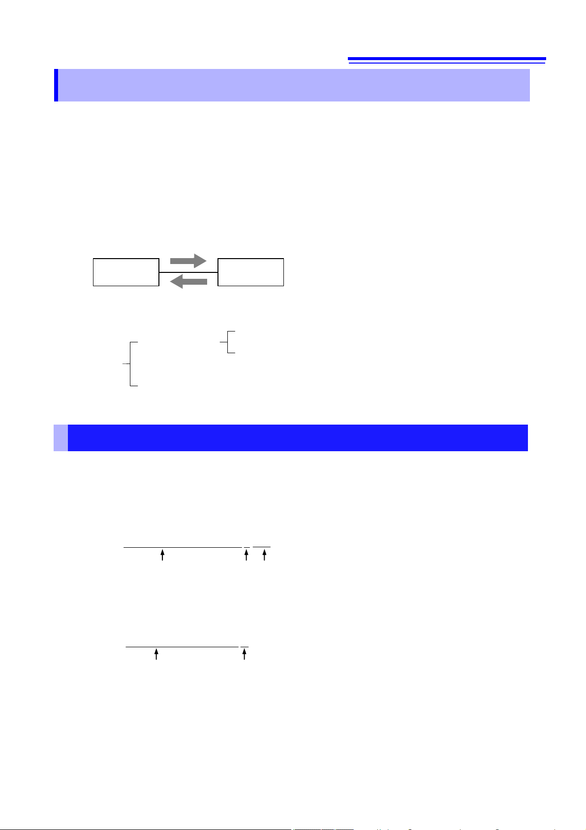
Program Messages
Controller
Instrument
Messages
Program Messages
Response Messages
Command Messages
Query Messages
In this publication, items relevant only to the DM7275-01, DM7275-02, DM7275-03, DM7276-01, DM7276-02, and
DM7276-03 are indicated as “the instrument.”
If the communication monitoring function is used at the time of program creation, commands and responses will be
conveniently displayed on the measurement screen. For information on the communication monitoring function, see
the instruction manual of the instruments.
Various messages are supported for controlling the instrument through the interfaces.
Messages can be either program messages, sent from the controller such as PC to the instrument, or response
messages, sent from the instrument to the controller.
Response Messages
Message types are further categorized as follows.
When issuing commands that contain data, make sure that the data is provided in the specified format.
Message Format
Program Messages
Program messages can be either Command Messages or Query Messages.
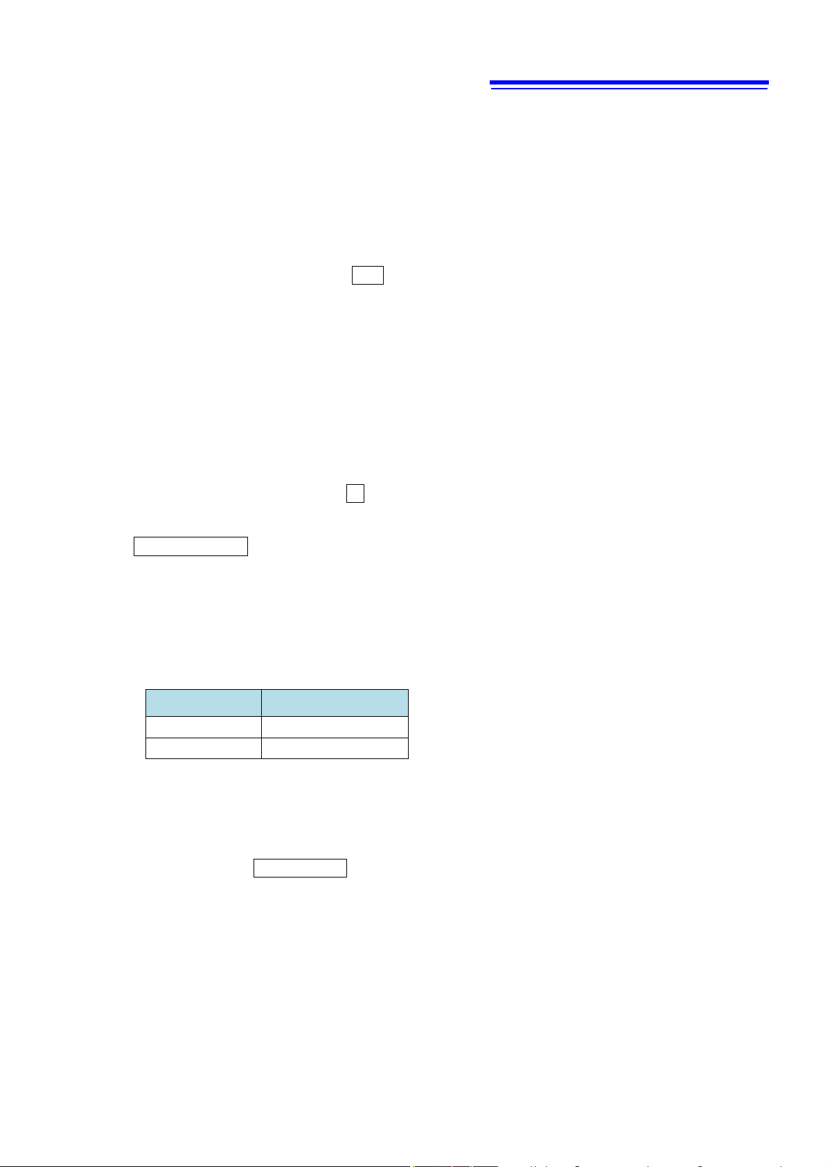
(1) Command Messages
Instructions to control the instrument, such as to change settings or reset
Example: (instruction to set the measurement range)
:VOLTAGE:DC:RANGE 100
Header portion
Space Data portion
(2) Query Messages
Requests for responses relating to results of operation or
measurement, or the state of instrument settings
Example: (request for the current measurement range)
:VOLTAGE:DC:RANGE?
Header portion
See: “Headers (p.2)”, “Separators (p.3)”, “Data Formats (p.4)”
Question mark
Page 7

2
Response Messages
*
When a query message is received, its syntax is checked and a response message is generated.
If an error occurs when a query message is received, no response message is generated for that query.
Command Syntax
Command names are chosen to mnemonically represent their function, and can be abbreviated. The full
command name is called the “long form”, and the abbreviated name is called the “short form”.
The command references in this manual indicate the short form in upper-case letters, extended to the long form in
lower case letters, although the commands are not case-sensitive in actual usage.
FETCH?
FETC?
FET?
Response messages generated by the instrument are in long form and in upper case letters.
OK (long form)
OK (short form)
Error
Headers
Headers must always be prefixed to program messages.
(1) Command Program Headers
There are three types of commands: Simple, Compound and Standard.
• Headers for Simple Commands
This header type is a sequence of letters and digits
:ABORt
• Headers for Compound Commands
These headers consist of multiple simple command type headers separated by colons “:”
:VOLTage:DC:RANGe
• Headers for Standard Commands
This header type begins with an asterisk “*”, indicating that it is a standard command defined by IEEE 488.2.
RST
(2) Query Program Header
These commands are used to interrogate the instrument about the results of operations, measured values and
the current states of instrument settings.
As shown by the following examples, a query is formed by appending a question mark “?” after a program
header.
:FETCh?
VOLTage:DC:RANGe?
Characters within square brackets [ ] may be omitted.
[:SENSe:]VOLTage:DC:RANGe
Either form is valid.
:SENSe:VOLTage:DC:RANGe
VOLTage:DC:RANGe
Page 8

3
Message Terminators
This instrument recognizes the following message terminators (delimiters).
[RS-232C/USB/LAN]
• CR
• CR+LF
[GP-IB]
• LF
• CR+LF
• EOI
• LF with EOI
Depending on the instrument’s interface settings, the following can be selected as the terminator for response
messages.
For information on settings, see “Delimiter Setting” (p.58).
[RS-232C/USB/LAN]
• CR+LF
[GP-IB]
• LF with EOI (default setting)
• CR+LF with EOI
Separators
(1) Message Unit Separator
Multiple messages can be written in one line by separating them with semicolons “;”.
:VOLTAGE:DC:RANGE 10;∗IDN?
• When messages are combined in this way and if one command contains an error, all subsequent messages up
to the next terminator will be ignored.
(2) Header Separator
In a message consisting of both a header and data, the header is separated from the data by a space “ ” (ASCII
code 20H).
:VOLTAGE:DC:RANGE 10
(3) Data Separator
In a message containing multiple data items, commas are required to separate the data items from one another.
:SYSTEM:DATE 15,1,1
Page 9
4
Ω
@
°C
$
Data Formats
The instrument uses character data, decimal numeric data and character string data depending on the command.
(1) Character Data
Character data always begins with an alphabetic character, and subsequent characters may be either
alphabetic or numeric. Character data is not case-sensitive, although response messages from the instrument
are only upper case. When the command data portion contains <1/0/ON/OFF>, the operation will be similar to
when 0 is OFF and 1 is ON.
:VOLTAGE:DC:RANGE:AUTO OFF
(2) Decimal Numeric Data
Three formats are used for numeric data, identified as NR1, NR2, and NR3. Numeric values may be signed or
unsigned. Unsigned numeric values are handled as positive values. Values exceeding the precision handled by
the instrument are rounded to the nearest valid digit.
• NR1 Integer data (e.g.: +12, -23, 34)
• NR2 Fixed-point data (e.g.: +1.23, -23.45, 3.456)
• NR3 Floating-point exponential representation data (e.g.: +1.0E-2, -2.3E+4)
The term “NRf format” includes all three of the above numeric decimal formats.
The instrument accepts NRf format data. The format of response data is specified for each command, and the
data is sent in that format.
:STATus:OPERation:ENABle 49
:FETCH?
+102.20192E-03
(3) Character string data
• Character string data is enclosed by quotation marks.
• This type of data consists of 8-bit ASCII characters
• Characters that cannot be handled by the instrument cause an error.
• The following two characters are different for the instrument setting and communications setting. (Scaling Unit
and Label Display Function)
Instrument setting Communication setting
*Only Scaling Unit and
with remote command.
• As for quotation marks, the sender form the instrument uses double quotes (”) only, while the receiver receives
both double quotes and single quotes (’).
Label Display Function are supported. About other functions, Ω and °C cannot be set
:SYSTem:LABel “LABEL_01”
[GP-IB]
The instrument does not fully support IEEE 488.2. As much as possible, please use the data formats shown in
the Reference section.
Page 10

5
Compound Command Header Omission
When several commands having a common header are combined to form a compound command
(e.g., :CALCulate:SCALe:PARameterA and :CALCulate:SCALe:PARameterB) if they are written together in
sequence, the common portion (here, :CALCulate:SCALe) can be omitted after its initial occurrence.
This common portion is called the “current path” (analogous to the path concept in computer file storage), and until it
is cleared, the interpretation of subsequent commands presumes that they share the same common portion.
This usage of the current path is shown in the following example:
Full expression
:CALCulate:SCALe:PARameterA 1.0; :CALCulate:SCALe:PARameterB 0.0
Compacted expression
:CALCulate:SCALe:PARameterA 1.0; PARameterB 0.0
This portion becomes the current path, and can be omitted from the messages immediately following.
The current path is cleared when the power is turned on, when reset by key input, by a colon “:” at the start of a
command, and when a message terminator is detected.
Standard command messages can be executed regardless of the current path. They have no effect upon the
current path.
A colon “:” is not required at the start of the header of a Simple or Compound command. However, to avoid
confusion with abbreviated forms and operating mistakes, we recommend always placing a colon at the start of a
header.
Output Queue and Input Buffer
Output Queue
Response messages are stored in the output queue until read by the controller. The output queue is also cleared
in the following circumstances:
• Power on
• Device clear [GP-IB]
• Query Error
Input Buffer
The input buffer capacity of the instrument is 256 bytes.
If 256 bytes are allowed to accumulate in this buffer so that it becomes full, the USB and GP-IB interface bus enters
the waiting state until space is cleared in the buffer.
The RS-232C interface may not process data beyond 256 bytes.
Note: Ensure that the no command ever exceeds 256 bytes.
Page 11
6
bit7
bit6
bit5
bit4
bit3
bit2
bit1
bit0
SRQ
MSS
Logical
sum
bit7
bit6
bit5
bit4
bit3
bit2
bit1
bit0
Service Request
(SRER)
Standard Event Register Description
Error occurrence information
Service Request
SRQ occurrence
Output Queue data information
Standard Operation Register information
Status Query Register information
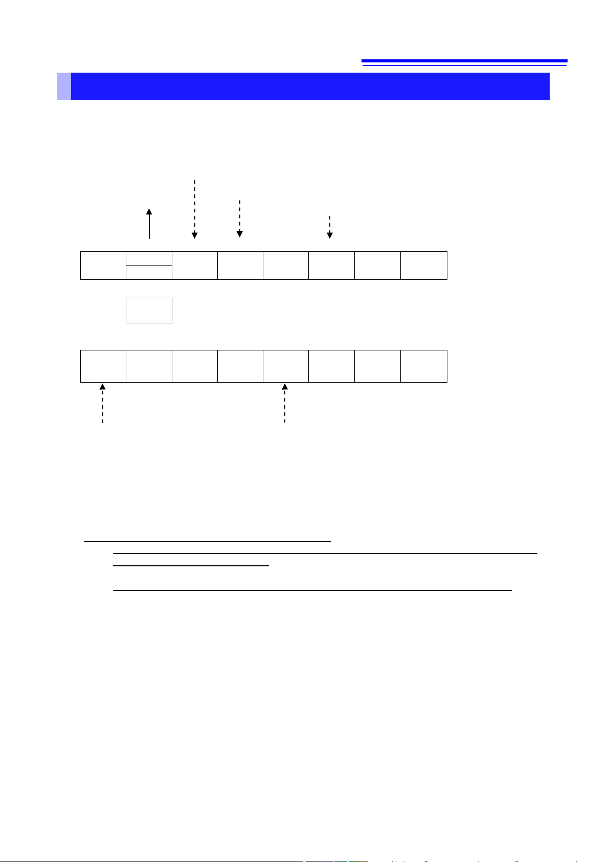
Status Byte Register
[GP-IB]
This instrument implements the status model defined by IEEE 488.2 with regard to the serial poll function using
the service request line. The term “event” refers to any occurrence that generates a service request.
ESB1
↓ ↑ ↓ ↓ ↓ ↓ ↓ ↓
&→
↑ ↑ ↑ ↑ ↑ ↑ ↑
ESB1 0
The Status Byte Register contains information about the event registers and the output queue.
selected from this information by masking with the Service Request Enable Register. When any bit selected by the
mask is set, bit 6 (MSS; the Master Summary Status) of the Status Byte Register is also set, which generates an
SRQ (Service Request) message and dispatches a service request.
ESB MAV ESB0 ERR Unused Unused
← & & & & & &
ESB MAV ESB0 ERR Unused Unused
Overview of Service Request Occurrence
Status Byte
Register (STB)
Enable Register
Required items are
Note: SRQ (Service Request) is a GP-IB function only.
However, STB (Status Byte Register) information can be acquired with RS-232C, USB or
LAN using the *STB? command.
STB (Status Byte Register) information can be acquired using the *STB? command.
[RS-232C/USB/LAN]
RS-232C/USB/LAN does not provide a function for issuing service requests. Still, SRER setup and STB reading
are available.
Page 12

7
Event Status (logical sum) bit 1
This is the logical sum of the Standard Operation Register.
Set to 1 when a service re
This is the logical sum of the other bits of the Status Byte Register.
Standard Event Status (logical sum) bit
This is logical sum of the Standard Event Status Register.
Message available
Indicates that a me
Event Status (logical sum) bit 0
This is the logical sum of the Status Query Register.
Error bit
Set to 1 when error information is present.
Reset using :SYSTem.ERRor? to output error information.
Unused
Unused
Status Byte Register (STB)
During serial polling, the contents of the 8-bit Status Byte Register are sent from the instrument to the controller.
When any Status Byte Register bit enabled by the Service Request Enable Register has switched from 0 to 1, the
MSS bit becomes 1. Consequently, the SRQ bit is set to 1, and a service request is dispatched.
The SRQ bit is always synchronous with service requests, and is read and simultaneously cleared during serial
polling. Although the MSS bit is only read by an *STB? query, it is not cleared until a clear event is initiated by the
*CLS command.
Bit 7 ESB1
SRQ
Bit 6
MSS
Bit 5 ESB
Bit 4 MAV
Bit 3 ESB0
Bit 2 ERR
Bit 1
Bit 0
quest is dispatched.
ssage is present in the output queue.
Service Request Enable Register (SRER)
This register masks the Status Byte Register. Setting a bit of this register to 1 enables the corresponding bit of the
Status Byte Register to be used.
Page 13
8
bit0
bit1
bit2
bit3
bit4
bit5
bit6
bit7
bit8
bit9
bit10
bit11
bit12
bit13
bit14
bit15
bit0
bit1
bit2
bit3
bit4
bit5
bit6
bit7
bit8
bit9
bit10
bit11
bit12
bit13
bit14
bit15
Out-of-range
voltage
Out-of-range
temperature
Lower threshold FAIL
Upper threshold FAIL
Out of BIN
Memory is full
Contact error
:STATus:QUEStionable:CONDition?
:STATus:QUEStionable:EVENt?
<1>
<2>
<4>
<8>
<16>
<32>
<64>
<128>
<256>
<512>
<1024>
<2048>
<4096>
<8192>
<16384>
<32768>
:STATus:QUEStionable:ENABle
:STATus:QUEStionable:ENABle?
Status Query Resister
COND
EV EN
bit0
bit1
bit2
bit3
bit4
bit5
bit6
bit7
Operation complete
*ESR?
*ESE
*ESE?
<1>
<2>
<4>
<8>
<16>
<32>
<64>
<128>
Standard Event StatusRegister
EV EN
Query error
Device-specific error
Execution error
Command error
Power-on
bit0
bit1
bit2
bit3
bit4
bit5
bit6
bit7
bit8
bit9
bit10
bit11
bit12
bit13
bit14
bit15
bit0
bit1
bit2
bit3
bit4
bit5
bit6
bit7
bit8
bit9
bit10
bit11
bit12
bit13
bit14
bit15
Setting changed
Measurement complete (EOM)
:STATus:OPERation:CONDition?
:STATus:OPERation:EVENt?
<1>
<2>
<4>
<8>
<16>
<32>
<64>
<128>
<256>
<512>
<1024>
<2048>
<4096>
<8192>
<16384>
<32768>
:STATus:OPERation:ENABle
:STATus:OPERation:ENABle?
Standard Operation Register
COND
EV EN
During measurement
Trigger wait
Memory data threshold reached
Instrument locked
bit0
bit1
bit2
bit3
bit4
bit5
bit6
bit7
Serial poll
*STB?
*SRE
*SRE?
<1>
<2>
<4>
<8>
<16>
<32>
<64>
<128>
Status Byte Register
EV EN
:SYSTem:ERRor?
Output data?
Logical
sum
Logical sum
Logical
sum
Logical sum
Returns bit status at the time of query receipt
rather than the held value.
Each bit is not cleared even if the query
result is returned.
When 1 is set for each bit, the status is held
until the query result is returned.
When 1 is set for each bit, the status is held
until the query result is returned.
Returns bit status at the time of query receipt
rather than the held value.
Each bit is not cleared even if the query result is
returned.
When 1 is set for each bit, the status is held
until the query result is returned.
Returns the status when *STB? is received.
Each bit is not cleared even if the *STB query result is
returned. (It is necessary to perform a query for each
event register and clear the occurrence or execute *CLS.)
AND output of EV and EN
AND output of
EV and EN
AND output of
EV and EN
AND output of
EV and EN
:SYSTem:ERRor?
Hold
Event Registers
Page 14

9
Power-On Flag
Set to 1 when the power is turned on, or upon recovery from an
outage.
Unused
Command error (The command to the message terminator
This bit is set to 1 when a received command contains a
• Received a command not supported by the instrument
This bit is set to 1 when a received command cannot be
Execution is prevented by some other operation being
performed
This bit is set to 1 when a command cannot be executed due to
or an
execution error.
This bit is set to 1 when a query error is detected by the output
• When data in the output queue has been lost
Request Control
It indicates the completion of operations of all messages up to
the “*OPC” command
Standard Event Status Register (SESR)
The Standard Event Status Register is an 8-bit register. If any bit in the Standard Event Status Register is set to 1
(after masking by the Standard Event Status Enable Register), bit 5 (ESB) of the Status Byte Register is set to 1.
See: “Standard Event Status Register (SESR) and Standard Event Status Enable Register
(SESER)
The Standard Event Status Register is cleared in the following situations:
• When a *CLS command is executed
• When an event register query (
• When the instrument is powered on
” (p.10)
*ESR?) is executed
Bit 7 PON
URQ
Bit 6
Bit 5 CME
Bit 4 EXE
Bit 3
(Unused)
DDE
(Unused)
Not used by this instrument
User Request
is ignored.)
syntactic or semantic error:
• Program header error
• Incorrect number of data parameters
• Invalid parameter format
Execution Error
executed for some reason.
• The specified data value is outside of the set range
• The specified setting data cannot be set
•
Not used by this instrument
Device-Dependent Error
some reason other than a command error, a query error
Query Error (the output queue is cleared)
Bit 2 QYE
queue control.
• When the data overflows the output queue
Bit 1
Bit 0 OPC
RQC
(Unused)
Not used by this instrument
Operation Complete
・It indicates the execution of an “
・
*OPC” command.
Page 15

10
Status Byte Register (STB)
SRQ
PON
URQ
CME
EXE
DDE
QYE
RQC
OPC
PON
URQ
CME
EXE
DDE
QYE
RQC
OPC
Standard Event Status Enable Register (SESER)
Standard Event Status Enable Register (SESER)
Setting any bit of the Standard Event Status Enable Register to 1 enables access to the corresponding bit of the
Standard Event Status Register.
Standard Event Status Register (SESR) and Standard Event Status Enable Register (SESER)
bit6 bit5 bit4
MSS Standard Event Status Register (SESR)
ESB MAV
bit7 bit6 bit5 bit4 bit3 bit2 bit1 bit0
↑
↓ ↓ ↓ ↓ ↓ ↓ ↓ ↓
Logical sum ← & & & & & & & &
↑ ↑ ↑ ↑ ↑ ↑ ↑ ↑
bit7 bit6 bit5 bit4 bit3 bit2 bit1 bit0
Page 16

11
Bit 15
-
Unused
Bit 14
-
Unused
Set to 1 when an error occurs (cleared when details are acquired
from :SYSTem.ERRor?).
Bit 12
HOLD
Set to 1 when autohold is completed.
Bit 11
EOM
Set to 1 when measurement is completed.
Bit 10
LOCK
Set to 1 when the instrument is in the Remote state.
Set to 1 when the number of memory data reaches the number set
in :DATA:POINts:EVENt:THReshold.
or the last
normal measurement.
Bit 7
-
Unused
Bit 6
-
Unused
Bit 5
WAIT_TRG
Set to 1 when the instrument is in the trigger waiting state.
Bit 4
MEAS
Set to 1 when the instrument is in the measurement state.
Bit 3
-
Unused
Bit 2
-
Unused
Bit 1
-
Unused
Bit 0
-
Unused
Status Byte Register (STB)
Logical
sum
↑ ↑ ↑ ↑ ↑ ↑ ↑ ↑ ↑ ↑ ↑ ↑ ↑ ↑ ↑
↑
Enable register of the Standard Operation Register Group (:STATus:OPERation:ENABle)
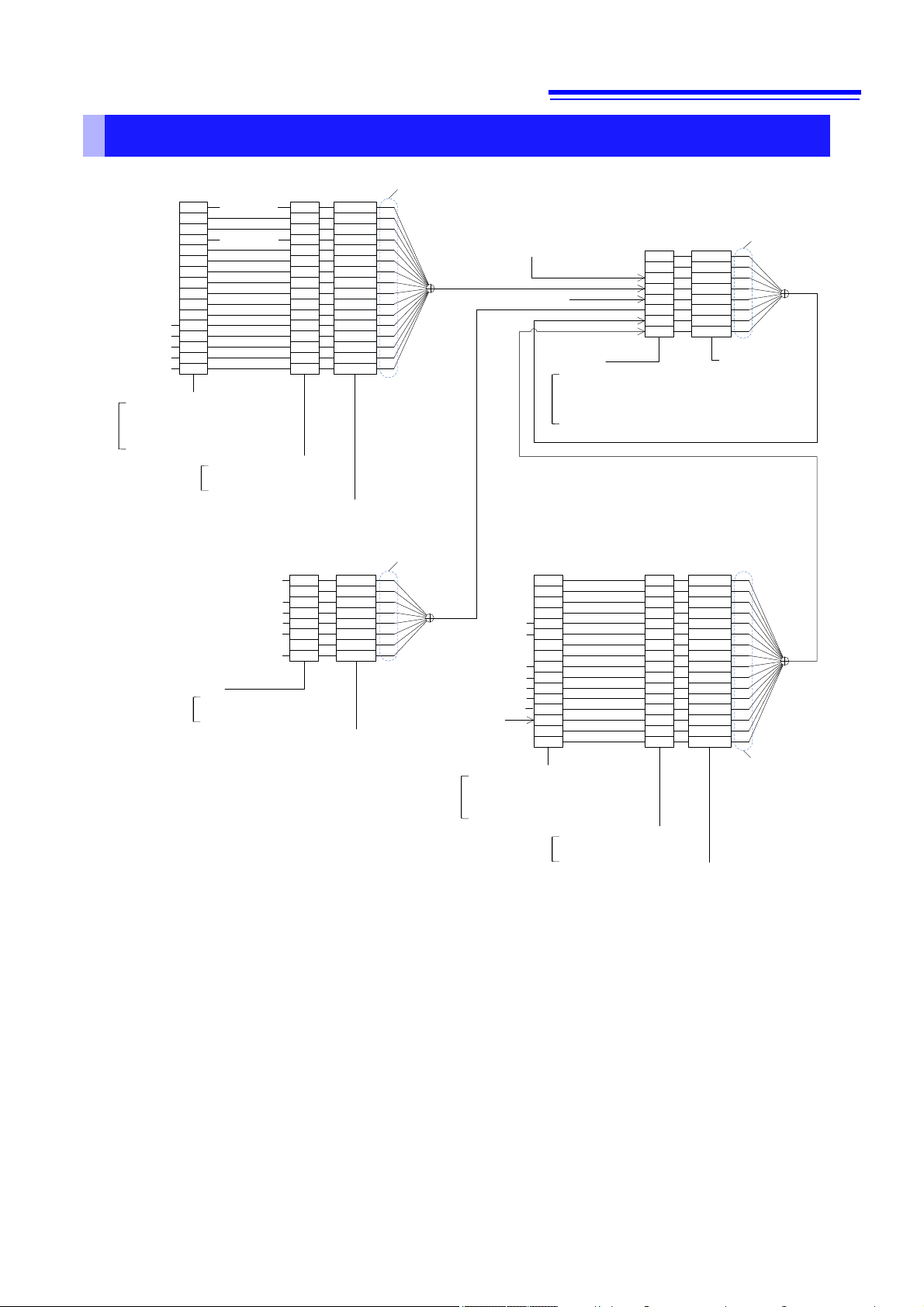
Device-Specific Event Status Registers
This instrument provides two Event Status Registers for controlling events. Each Event Status Register is a 16-bit
register.
When any bit in one of these Event Status Registers enabled by its corresponding Enable Register is set to 1, the
following happens:
• For Standard Operation Register, bit 7 (ESB1) of the Status Byte Register is set to 1.
• For Status Query Resister, bit 3 (ESB0) of the Status Byte Register is set to 1.
Event Status Registers 0 and 1 are cleared in the following situations:
• When a
• When an Event Status Register query is executed
(
:STATus:OPERation:EVENt?, :STATus:QUEStionable:EVENt?)
• When the instrument is powered on
*CLS command is executed
Standard Operation Register
Bit 13 ERR
Bit 9 MEM_RDY
Bit 8 SET Set to 1 when the setting is changed after the last :INIT
Event register of the Standard Operation Register Group
(:STATus:OPERation:EVENt?) and
enable register of the Standard Operation Register Group (:STATus:OPERation:ENABle)
bit7 bit6 bit5
SRQ/
ESB1
MSS
MAV
Event register of the Standard Operation Register Group (:STATus:OPERation:EVENt?)
bit15 bit14 bit13 bit12 bit11 bit10 bit9 bit8 bit7 bit6 bit5 bit4 bit3 bit2 bit1 bit0
↑
MEM
-
ERR HOLD EOM LOCK
_OVR
MEM
_RDY
SET - -
↓ ↓ ↓ ↓ ↓ ↓ ↓ ↓ ↓ ↓ ↓ ↓ ↓ ↓ ↓ ↓
← & & & & & & & & & & & & & & & &
bit15 bit14 bit13 bit12 bit11 bit10 bit9 bit8 bit7 bit6 bit5 bit4 bit3 bit2 bit1 bit0
- - ERR HOLD EOM LOCK
MEM
_RDY
SET - -
WAIT
MEAS - - - -
_TRG
WAIT
MEAS - - - -
_TRG
Page 17

12
Bit 15
CNT_ERR
Set to 1 when a contact error occurs.
Bit 14
MEM_OVR
Set to 1 when the internal measurement memory is full (5000 data).
Bit 13
OB
Set to 1 when the BIN measurement result is OUT OF BIN.
Bit 12
HI
Set to 1 when the comparator result is upper threshold FAIL.
Bit 11
LO
Set to 1 when the comparator result is lower threshold FAIL.
Bit 10
-
Unused
Bit 9
-
Unused
Bit 8
-
Unused
Bit 7
-
Unused
Bit 6
-
Unused
Bit 5
-
Unused
Bit 4
-
Unused
Bit 3
TMP_OVR
Set to 1 when the measurement temperature is outside the measurement range.
Bit 2
Unused
Bit 1
-
Unused
Bit 0
VLT_OVR
Set to 1 when the measurement voltage is outside the measurement range.
Status Byte Register (STB)
Logical
sum
↑ ↑ ↑ ↑ ↑ ↑ ↑ ↑ ↑ ↑ ↑ ↑ ↑ ↑ ↑
↑
Enable register of the Status Query Register Group (:STATus:OPERation:ENABle)
Status Query Register
Event register of the Status Query Register Group (:STATus:QUEStionable:EVENt?) and
enable register of the Status Query Register Group (:STATus:QUEStionable:ENABle)
bit4 bit3 bit2
MAV ESB0 ERR
↑
← & & & & & & & & & & & & & & & &
Event register of the Status Query Register Group (:STATus:QUEStionable:EVENt?)
bit15 bit14 bit13 bit12 bit11 bit10 bit9 bit8 bit7 bit6 bit5 bit4 bit3 bit2 bit1 bit0
CNT_
MEM
ERR
_OVR
↓ ↓ ↓ ↓ ↓ ↓ ↓ ↓ ↓ ↓ ↓ ↓ ↓ ↓ ↓ ↓
bit15 bit14 bit13 bit12 bit11 bit10 bit9 bit8 bit7 bit6 bit5 bit4 bit3 bit2 bit1 bit0
CNT_
MEM
ERR
_OVR
OB HI LO - - - - - - -
OB HI LO - - - - - - -
TMP_
OVR
TMP_
OVR
- -
- -
VLT_
OVR
VLT_
OVR
Page 18

13
Register
Read
Write
*STB?
-
*SRE?
*SRE
*ESR?
-
*ESE?
*ESE
(Status data)
:STATus:OPERation
:CONDition?
-
(Event data)
:STATus:OPERation
:EVENt?
-
:STATus:OPERation
:ENABle?
:STATus:OPERation
:ENABle
(Status data)
:STATus:QUEStiona
ble:CONDition?
-
:STATus:OPERation
:EVENt?
-
:STATus:QUEStiona
ble:ENABle?
:STATus:QUEStiona
ble:ENABle
Command
Description
GTL
Go To Local
Cancels the Remote state and enters the Local state.
LLO
Local Lock Out
Disables all keys, including the Local key.
DCL
Device CLear
Clears the input buffer and the output queue.
Device Clear
Trigger
selected, processes one sampling.
Register Reading and Writing
Status Byte Register
Service Request Enable Register
Standard Event Status Register
Standard Event Status Enable Register
Event register of the Standard Operation Register Group
Event Register of Standard Operation Register Group
Enable Register of Standard Operation Register Group
Event Register Query of Status Query Register Group
Event Register Query of Status Query Register Group
(Event data)
Enable Register of Status Query Register Group
GP-IB Commands
The following commands can be used for performing interface functions.
SDC Selected
GET Group Execute
Clears the input buffer and the output queue.
When an external trigger (trigger source <EXTERNAL>) is
Page 19
14
Measurement Range
Measured Value
±OvrRng
Measurement Fault
100 mV
± □□□.□□□□□E-03
±990.00000E+35
+991.00000E+35
1 V ± □□□□.□□□□E-03
±9900.0000E+34
+9910.0000E+34
10 V ± □□.□□□□□□E+00
±99.000000E+36
+99.100000E+36
100 V ± □□□.□□□□□E+00
±990.00000E+35
+991.00000E+35
1000 V
± □□□□.□□□□E+00
±9900.0000E+34
+9910.0000E+34
Measured Value
±OvrRng
Measurement Fault
± □.□□□□□□□□E±0□
±9.90000000E+37
+9.91000000E+37
Measurement Value Formats
In the measured value format settings, the measurement format that can be acquired from :FETCh?, :READ?,
MEASure[:VOLTage]:DC?
• Voltage: Unit V (When :SYSTem:COMMunicate:FORMat FIX is set)
Note:•Position of the decimal point and exponent is changed by setting of the scalling.
Please refer to instruction manual of the instruments about the scalling.
•
When the number of digits for the integer is short, 0 is entered.
Example) When the measurement value is 1 V in 1000 V range, the measurement value is
•The mantissa changes depending on the setting number of digits.
• Voltage: Unit V (When :SYSTem:COMMunicate:FORMat FLOAT is set)
can be changed.
presented as +0001.0000E+00.
Note: The measurement value is presented as a floating-point value with eight decimal places.
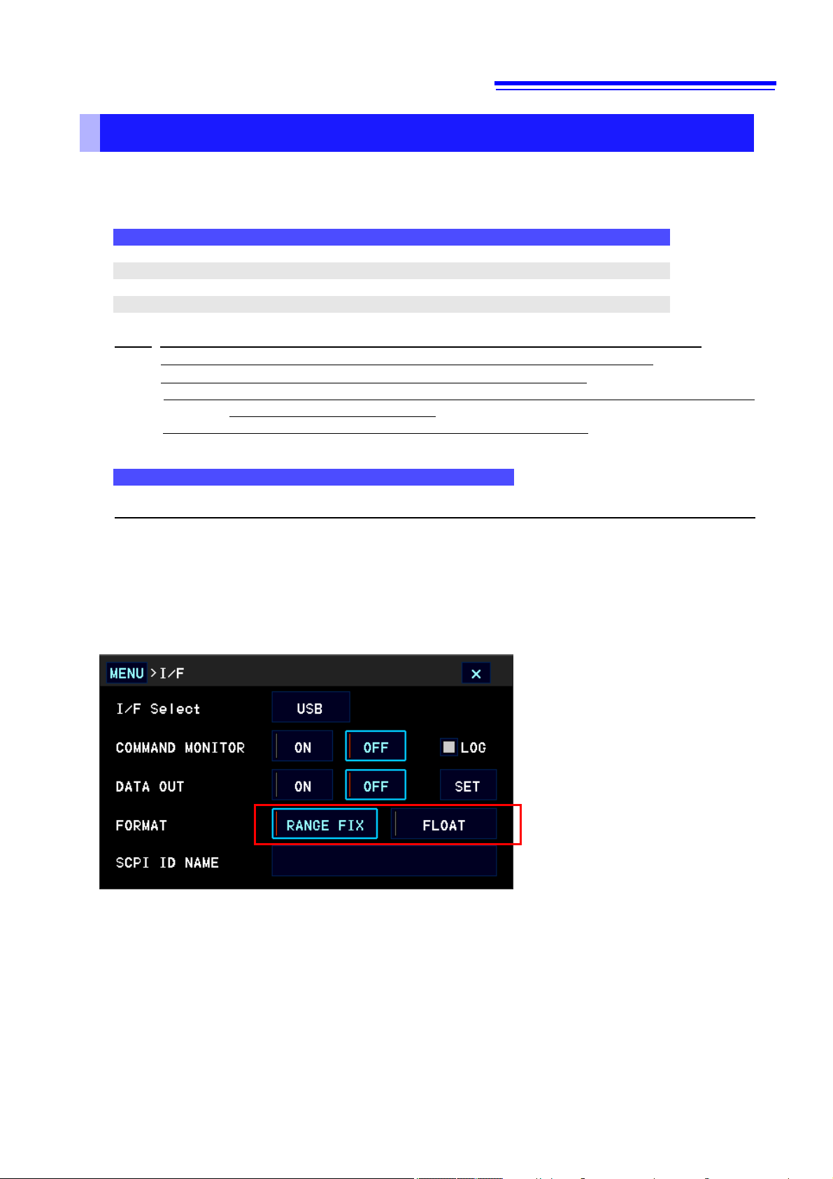
The format of measurment values can be changed in any of the following settings.
• By communications commands
Change the format in
:SYSTem:COMMunicate:FORMat FLOAT/FIX. (See: Data Output Settings p.36)
• In the instrument screen
Page 20

15
GP-IB Address
- 1 - - -
1
RS-232C setting (baud rate)
-
9600 - - - 9600
LAN IP Address
-
0.0.0.0 - -
-
0.0.0.0
LAN sub-net mask
-
255.255.255.0
- - -
255.255.255.0
LAN default gateway
-
0.0.0.0 - -
-
0.0.0.0
LAN port
-
23 - - - 23
Device-specific functions (range, etc.)
-
-
-
Output Queue
-
-
Input Buffer
●
-
-
Status Byte Register
●
-
●*1
●*2 ●
Event Registers
●*3
-
-
●
Enable Register
●
- - -
Current path
●
-
-
Response message terminator (GP-IB)
-
LF+EOI - -
-
LF+EOI
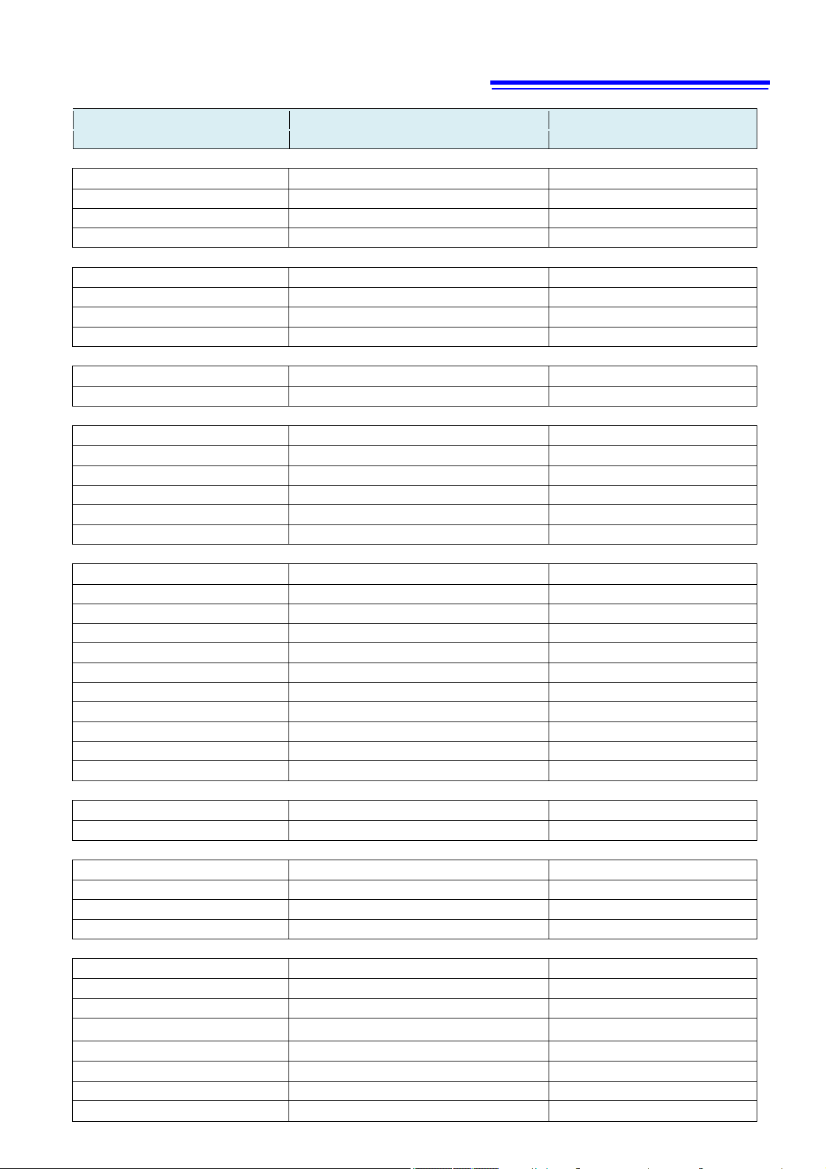
*3. Except the PON bit (bit 7).
Initialization Items
Initialization Method
Item
*1. Only the MAV bit (bit 4) is cleared.
*2. All bits except the MAV bit are cleared.
At
Power-on
● ●
●
●
●
●
Key
Reset
●
●
*RST
Command
●
Device Clear
(GP-IB only)
●
●
●
*CLS
Command
●
Factory
Default
●
●
●
●
●
Page 21

16
Command
Execution time (except communication time)
*RST
:STATus:PRESet
[:SENSe:]VOLTage:DC:RANGe
700 ms or less
[:SENSe:]VOLTage[:DC]:NPLCycles
2 ms or less
:FETCh?
10 ms or less
:READ?
Measurement time + 15 ms or less
*RCL
700 ms or less
*TST?
20 ms or less
Commands other than those above
10 ms or less
Command Execution Time
Command execution time indicates the time for analyzing and processing long form commands.
However, the command execution time for commands with data is the time described according to the data format
specified in the <data portion>.
• Display delays may occur depending on the frequency of communication processes and process contents.
• All commands except *TRG and :INIT are processed sequentially.
• In communications with the controller, time must be added for data transmission. USB and GP-IB transfer time depends
on the controller.
The RS-232C transfer time, with start bit 1, data length 8, no parity, and stop bit 1, has a total of 10-bit. When the transfer
speed (baud rate) setting is N bps, the general result will be as follows:
Transfer time T [1 character/sec] = Baud rate N [bps]/10 [bits]
Since a measurement value is 17 characters, a 1 data transfer time will be 17/T.
(Example) For 9600 bps, 17/(9600/10) = Approx. 17 ms
• Wait until measurements stabilize after a change before using a setting command.
:SYSTem:PRESet
Errors During Communications
An error occurs when messages are executed in the following cases:
• Command Error
When message syntax (spelling) is invalid
When the data format in a command or query is invalid
• Query Error
When a
• Execution Error
When any character or numerical data that is not specified is set
response
message cannot be sent from the instrument as the controller cannot receive it
700 ms or less
Page 22

17
(<Manufacturer name>,<Model name>,<Serial number>,<Software
version>)
Sets OPC of SESR after all operations that are being
executed are completed.
Responds with ASCII “1” after all operations that are
being executed are completed.
Executes subsequent commands after command
processing is completed.
Clears the Event Registers and the Status Byte
Register.
Writes the Standard Event Status Enable Register
(SESER).
Reads the Standard Event Status Enable Register
(SESER).
Reads and clears the Standard Event Status Register
(SESR).
Writes the Standard Event Status Enable Register
(SRER).
Reads the Standard Event Status Enable Register
(SRER).
Queries the Condition Register of the Standard
Operation Register Group.
Queries the total bit number of the Event Register of
the Standard Operation Register Group.
Set the Enable Register of the Standard Operation
Register Group.
Queries the Enable Register of the Standard
Operation Register Group.
Queries the Condition Register of the Status Query
Register Group.
Queries the total bit number of the Event Register of
the Status Query Register Group.
Sets the Enable Register of the Status Query
Register Group.
Queries the Enable Register of the Status Query
Register Group.
• When :SYST:COMM:FORM FLOAT is set
(<Measurement value>)
• When :SYST:COMM:FORM FLOAT is set
(<Measurement value>)
2 Message List
Messages Data Description
[ ]: Omissible [ ]: Omissible, ( ): Response data
Standard Commands
*IDN?
*OPT? (<0/GPIB>,<LAN>,<0/RS232C>) Identifies installed options.
*RST
*TST? (<PASS/FAIL>) Initiates a self-test and queries the result.
*SAV <Panel No.> Saves the measurement conditions (panel save).
*RCL <Panel No.> Reads the measurement conditions (panel load).
*TRG Requests sampling.
*OPC
*OPC?
*WAI
*CLS
*ESE 0 to 255
*ESE? (0 to 255)
*ESR? 0 to 255
*SRE 0 to 255
*SRE? (0 to 255)
*STB? (0 to 255) Reads the status byte and MSS bit.
Event Registers
:STATus:OPERation:CONDition?
(0~16176)
Queries the Device ID (Identify code).
Initializes the device.
:STATus:OPERation[:EVENt]?
:STATus:OPERati on:ENABle
:STATus:OPERati on:ENABle?
:STATus:QUEStionable:CONDition?
:STATus:QUEStionable[:EVENt]?
:STATus:QUEStionable:ENABle
:STATus:QUEStionable:ENABle?
Reading Measured Values
:FETCh?
:READ?
:MEASure[:VOLTage]:DC? (<Measurement value>) Measures the voltage with the range specified.
:MEASure:TEMPerature? (<Temperature measurement value>) Reads the temperature measurement value.
:DATA:LAST? (<Measurement value>) Reads the most recent measurement.
:ABORt Cancels the measurement.
:SYSTem:COMMunicate:FORMat < FIX/FLOAT > Sets the output format of measurement values.
:SYSTem:COMMunicate:FORMat? (<FIX/FLOAT>) Queries the output format of measurement values.
Self-Test
:TEST:ALL? (< PASS/FAIL >) Initiates a self-test and queries the result.
(0~16176)
0~65535
(0~16177)
(0~63497)
(0~63497)
0~65535
(0~63775)
(<Measurement value 1>, <Measurement value 2>, ...
<Measurement value N>)
• When :SYST:COMM:FORM FIX is set
(<Measurement value 1>, <Measurement value 2>, ...
<Measurement value N>)
• When :SYST:COMM:FORM FIX is set
Reads the most recent measurement.
Measurement (waits for trigger and reads the
measured values)
Page 23
18
<Condition>
(<Condition>,<Type>,<Count>)
Clock
:SYSTem:DATE <Year>,<Month>,<Day> Sets the system date.
:SYSTem:DATE? (<Year>,<Month>,<Day>) Queries the system date.
:SYSTem:TIME <Hour>,<Minute>,<Second> Sets the clock.
:SYSTem:TIME? <Hour>,<Minute>,<Second> Queries the clock.
Measurement Range
[:SENSe:]VOLTage:DC:RANGe <Measurement range/MAX/MIN/DEFault> Sets the measurement range.
[:SENSe:]VOLTage:DC:RANGe? (<Measurement range>) Queries the measurement range.
[:SENSe:]VOLTage:DC:RANGe:AUTO < 1/0/ON/OFF > Sets and queries the measurement AUTO range.
[:SENSe:]VOLTage:DC:RANGe:AUTO? (< 1/0 >) Queries the measurement AUTO range.
Measurement Function
[:SENSe:]FUNCtion[:ON] < TEMPerature/VOLTage[:DC] > Sets the measurement range.
[:SENSe:]FUNCtion[:ON]? ("VOLT:DC") Queries the measurement range.
Measurement Speed
[:SENSe:]VOLTage[:DC]:NPLCycles <Integral time(PLC)/MAX/MIN/DEFault/SLOW/MEDium/FAST> Sets the integral time(PLC).
[:SENSe:]VOLTage[:DC]:NPLCycles? (<Integral time(PLC)>) Queries the integral time(PLC).
[:SENSe:]VOLTage[:DC]:APERture:ENABled < 1/0/ON/OFF > Sets ON/OFF of the integral time(sec).
[:SENSe:]VOLTage[:DC]:APERture:ENABled? (< 1/0 >) Queries the integral time(sec).
[:SENSe:]VOLTage[:DC]:APERture <Integral time(sec)/MAX/MIN/DEFault> Sets the integral time(sec).
[:SENSe:]VOLTage[:DC]:APERture? (<Integral time(sec)>) Queries the integral time(sec).
Trigger
:INITiate:CONTinuous < 1/0/ON/OFF > Set the continuous measurement.
:INITiate:CONTinuous? (< 1/0 >) Queries the continuous measurement.
:INITiate[:IMMediate] Initiates the trigger wait state.
:TRIGger:SOURce < IMMediate/ EXTernal/BUS > Sets the trigger source.
:TRIGger:SOURce? (< IMM/ EXT >) Queries the trigger source.
:SAMPle:COUNt <Number of measurements/MAX/MIN/DEFault> Sets the number of measurements.
:SAMPle:COUNt? (<Number of measurements>) Queries the number of measurements.
:TRIGger:DELay <Delay time(sec)/MAX/MIN/DEFault> Sets the trigger delay.
:TRIGger:DELay? (<Delay time(sec)>) Queries the trigger delay.
:TRIGger:DELay:AUTO <1/0/ON/OFF > Sets the trigger preset delay.
:TRIGger:DELay:AUTO? (< 1/0 >) Queries the trigger preset delay.
Setting Number of Digits
[:SENSe:]VOLTage:DIGits <Number of digits/MAX/MIN/DEFault> Sets the number of digits for voltage measurement.
[:SENSe:]VOLTage:DIGits? <Number of digits> Queries the number of digits for voltage measurement.
Label Display
:SYSTem:LABel:STAT e < 1/0/ON/OFF > Sets the label display function.
:SYSTem:LABel:STAT e? (< 1/0 >) Queries the label display function.
:SYSTem:LABel <Label name> Sets the label name.
:SYSTem:LABel? (<Label name>) Queries the label name.
Comparator
:CALCulate:LIMit[:STATe] < 1/0/ON/OFF > Executes the comparator.
:CALCulate:LIMit[:STATe]? (< 1/0 >) Queries the comparator.
:CALCulate:LIMit:BEEPer <Condition>,<Type>,<Count> Sets the buzzer.
:CALCulate:LIMit:BEEPer?
:CALCulate:LIMit:ABSolute <1/0/ON/OFF > Sets the absolute value judgment function.
:CALCulate:LIMit:ABSolute? (< 1/0 >) Queries the absolute value judgment function.
:CALCulate:LIMi t:UPPer:ENABle <1/0/ON/OFF > Sets the upper threshold enable.
:CALCulate:LIMit:UPPer:ENABle? (< 1/0 >) Queries the upper threshold enable.
Messages Data Description
[ ]: Omissible [ ]: Omissible, ( ): Response data
Queries the buzzer.
Page 24

19
Queries the comparator judgment continuous
function.
<BIN No.>
(<Upper threshold>)
<BIN No.>
(<Lower threshold>)
<Panel No.>
(<Panel No.>,<Panel name>)
<Panel No.>
(<Year, month, day, hour, minute, second>)
Messages Data Description
[ ]: Omissible [ ]: Omissible, ( ): Response data
:CALCulate:LIMit:UPPer[:DATA] <Upper threshold> Sets the upper threshold.
:CALCulate:LIMit:UPPer[:DATA]? (<Upper threshold>) Queries the upper threshold.
:CALCulate:LIMit:LOWer:ENABle <1/0/ON/OFF > Sets the lower threshold enable.
:CALCulate:LIMit:LOWer:ENABle? (< 1/0 >) Queries the lower threshold enable.
:CALCulate:LIMit:LOWer[:DATA] <Lower threshold> Sets the lower threshold.
:CALCulate:LIMit:LOWer[:DATA]? (<Lower threshold>) Queries the lower threshold.
:CALCulate:LIMit:DELay <1/0/ON/OFF > Sets the comparator judgment continuous function.
:CALCulate:LIMit:DELay? (< 1/0 >)
:CALCulate:LIMit:DELay:COUNt <Count> Sets the comparator judgment continuous count.
:CALCulate:LIMit:DELay:COUNt? (<Count>) Queries the comparator judgment continuous count.
:CALCulate:LIMit:CLEar[:IMMediate] Clears the comparator event status register.
:CALCulate:LIMit:RESult? (<HI/IN/LO/ERR/OFF>) Queries the comparator result.
BIN
:CALCulate:BIN[:STATe] <1/0/ON/OFF > Executes the BIN measurement.
:CALCulate:BIN[:STATe]? (< 1/0 >) Queries the BIN measurement.
:CALCulate:BIN:ENABle <Enabled pattern> Sets the enabled pattern.
:CALCulate:BIN:ENABle? (<Enabled pattern>) Queries the enabled pattern.
:CALCulate:BIN:UPPer <BIN No.>,<Upper threshold> Sets the upper threshold.
:CALCulate:BIN:UPPer?
:CALCulate:BIN:LOWer <BIN No.>,<Lower threshold> Sets the lower threshold.
:CALCulate:BIN:LOWer?
:CALCulate:BIN:RESult? (0 to 1024) Queries the BIN judgment result.
Saving and Reading Measurement Conditions
*SAV <Panel No.> Saves the measurement conditions (panel save).
*RCL <Panel No.> Reads the measurement conditions (panel load).
:SYSTem:PANel:CLEar <Panel No.> Deletes the panel.
:SYSTem:PANel:NAME <Panel No.>,<Panel name> Sets the panel name.
:SYSTem:PANel:NAME?
:SYSTem:PANel:DATE?
:MMEMory:STORe:STATe <File name> Saves the setting file to a USB flash drive.
:MMEMory:LOAD:STATe <File name> Reads the setting file from a USB flash drive.
:MMEMory:STATe:RECall:AUTO <1/0/ON/OFF > Sets the function for reading the panel at startup.
:MMEMory:STATe:RECal l:AUTO? (< 1/0 >) Queries the function for reading the panel at startup.
:MMEMory:STATe:RECall:SELect <Panel No.> Sets the panel No. to be read at startup.
:MMEMory:STATe:RECall:SELect? (<Panel No.>) Queries the panel No. to be read at startup.
Smoothing
:CALCulate:SMOothing[:STATe] <1/0/ON/OFF > Executes the smoothing function.
:CALCulate:SMOothing[:STATe]? (< 1/0 >) Queries the smoothing function.
:CALCulate:SMOothing:RESPonse (<Count/SLOW/MEDium/FAST>) Sets the smoothing count.
:CALCulate:SMOothing:RESPonse? (<Count>) Queries the smoothing count.
Hold
[:SENSe:]HOLD:AUTO <1/0/ON/OFF > Executes auto hold.
[:SENSe:]HOLD:AUTO? (< 1/0 >) Queries auto hold.
[:SENSe:]HOLD:BOUNd <Hold range/MAX/MIN/DEFault> Sets the auto hold range.
[:SENSe:]HOLD:BOUNd? (<Hold range>) Queries the auto hold range.
Contact Check
[:SENSe:]VOLTage:DC:CONTact:CAPacitance? (<Contact check measurement value>) Queries the contact check measurement value.
[:SENSe:]VOLTage:DC:CONTact:CAPacitance:STATe <1/0/ON/OFF > Executes contact check.
[:SENSe:]VOLTage:DC:CONTact:CAPacitance:STATe? (< 1/0 >) Queries contact check.
Queries the upper threshold.
Queries the lower threshold.
Queries the panel name.
Queries the date of saving the panel.
Page 25

20
[:SENSe:]VOLTage:DC:CONTact:CAPacitance:THRes
hold
[:SENSe:]VOLTage:DC:CONTact:CAPacitance:THRes
hold?
<Reference temperature(°C)/MAX/MIN/DEFault>,
<Temperature coefficient(ppm/°C)/MAX/MIN/DEFault>
(<Reference temperature(°C)/MAX/MIN/DEFault>,
<Temperature coefficient(ppm/°C)/MAX/MIN/DEFault>)
Sets the function for clearing the statistical calculation
result at the time of printing.
Queries the function for clearing the statistical
calculation result at the time of printing.
(<Mean>,<Standard deviation>,<Minimum value>,
<Maximum value>)
Queries the mean value, standard deviation,
minimum value, and maximum value.
(<Hi count>,<IN count>,<Lo count>, <Measurement fault count>,
<Out-of-range count>)
(<BIN 0 count>,....,<BIN 9 count>,<OUT count>,
<Measurement fault count>)
Messages Data Description
[ ]: Omissible [ ]: Omissible, ( ): Response data
<Threshold/MAX/MIN/DEFault> Sets the contact check threshold.
(<Threshold>) Queries the contact check threshold.
[:SENSe:]VOLTage:DC:CONTact:CAPacitance:TIME <Integral time(sec)/MAX/MIN/DEFault> Sets the contact check integral time.
[:SENSe:]VOLTage:DC:CONTact:CAPacitance:TIME? <Integral time(sec)> Queries the contact check integral time.
Switching Input Resistance
[SENSe:]VOLTage[:DC]:IMPedance:AUTO <1/0/ON/OFF > Sets the input resistance.
[SENSe:]VOLTage[:DC]:IMPedance:AUTO? (< 1/0 >) Queries the input resistance.
Zero Adjustment (NULL Function)
[:SENSe:]VOLTage:DC:NULL[:STATe] <1/0/ON/OFF > Executes zero adjustment.
[:SENSe:]VOLTage:DC:NULL[:STATe]? (< 1/0 >) Queries zero adjustment.
[:SENSe:]VOLTage:DC:NULL:VALue <Adjustment value/MAX/MIN/DEFault> Sets the zero adjustment value.
[:SENSe:]VOLTage:DC:NULL:VALue? <Adjustment value> Queries the zero adjustment value.
Temperature Correction (TC)
:CALCulate:TCORrect:STATe <1/0/ON/OFF > Executes temperature correction (TC).
:CALCulate:TCORrect:STATe? (< 1/0 >) Queries temperature correction (TC).
:CALCulate:TCORrect:PARameter
Sets temperature correction (TC).
:CALCulate:TCORrect:PARameter?
Scaling
:CALCulate:SCALe[:STATe] <1/0/ON/OFF > Executes the scaling function.
:CALCulate:SCALe[:STATe]? (< 1/0 >) Queries the scaling function.
:CALCulate:SCALe:PARameterA <Correction coefficient/MAX/MIN/DEFault> Sets the scaling correction coefficient.
:CALCulate:SCALe:PARameterA? (<Correction coefficient>) Queries the scaling correction coefficient.
:CALCulate:SCALe:PARameterB <Offset/MAX/MIN/DEFault> Sets the scaling offset.
:CALCulate:SCALe:PARameterB? (<Offset>) Queries the scaling offset.
:CALCulate:SCALe:UNIT:STATe <1/0/ON/OFF > Sets the scaling unit function.
:CALCulate:SCALe:UNIT:STATe? (< 1/0 >) Queries the scaling unit function.
:CALCulate:SCALe:UNIT <Unit> Sets the scaling unit.
:CALCulate:SCALe:UNIT? (<Unit>) Queries the scaling unit.
Statistical Functions
:CALCulate:AVERage[:STATe] < 1/0/ON/OFF > Executes the statistical calculation function.
:CALCulate:AVERage[:STATe]? (1) Queries the statistical calculation function.
:CALCulate:AVERage:CLEar[:IMMediate] Clears the statistical calculation result.
:CALCulate:AVERage:CLEar:PRINt <1/0/ON/OFF >
:CALCulate:AVERage:CLEar:PRINt? (< 1/0 >)
:CALCulate:AVERage:COUNt? (<Number of data>) Query the number of statistical calculation data
:CALCulate:AVERage:ALL?
:CALCulate:AVERage:SDEViation? (<Standard deviation>) Queries the standard deviation.
:CALCulate:AVERage:AVERage? (<Mean>) Queries the mean value.
:CALCulate:AVERage:MINimum? (<Mi nimum value>) Queries the minimum value.
:CALCulate:AVERage:MAXimum? (<Maximum value>) Queries the maximum value.
:CALCulate:AVERage:PTPeak? (<Peak to Peak value>) Queries the Peak to Peak value.
:CALCulate:AVERage:LIMit?
:CALCulate:AVERage:BIN?
:CALCulate:AVERage:CP? (< Cp >,< CpK >) Queries the process capability indices.
Key-Lock
:SYSTem:KLOCk <1/0/ON/OFF > Sets the key-lock state.
:SYSTem:KLOCk? (< 1/0 >) Queries the key-lock state.
Queries temperature correction (TC).
Queries the comparator result.
Queries the BIN result.
Page 26
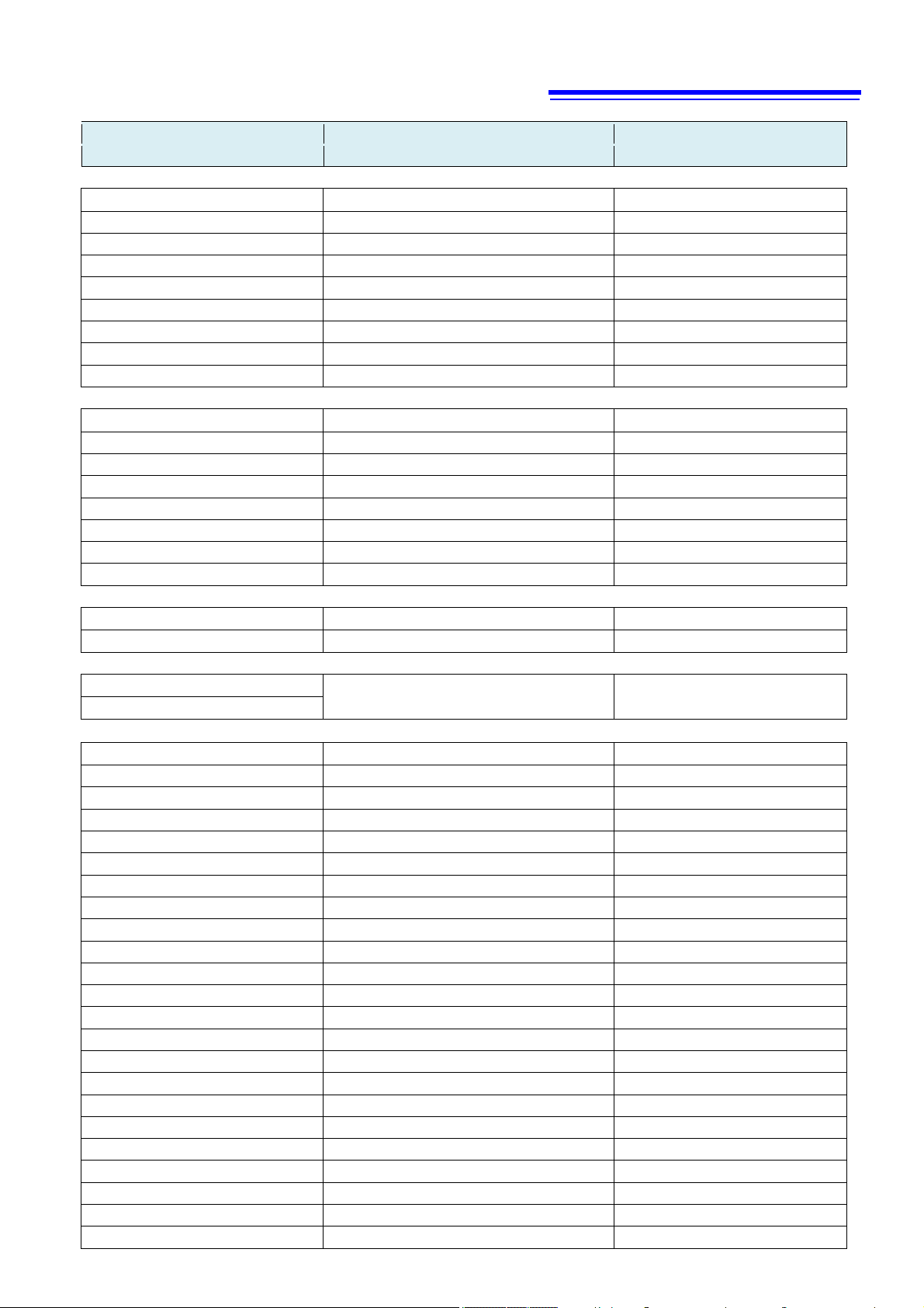
21
Messages Data Description
[ ]: Omissible [ ]: Omissible, ( ): Response data
Sound Settings
:SYSTem:CLICk[:STATe] <1/0/ON/OFF > Sets the key clicking sound.
:SYSTem:CLICk[:STATe] ? (< 1/0 >) Queries the key clicking sound.
:SYSTem:HOLD:BEEPer:STATe <1/0/ON/OFF > Sets the key hold sound.
:SYSTem:HOLD:BEEPer:STATe? (< 1/0 >) Queries key hold sound.
:SYSTem:BEEPer:STATe <1/0/ON/OFF > Sets the error beeping sound.
:SYSTem:BEEPer:STAT e? (< 1/0 >) Queries error beeping sound.
:SYSTem:BEEPer:VOLume <Volume/MAX/MIN/DEFault> Sets the volume.
:SYSTem:BEEPer:VOLume? (<Volume>) Queries the volume.
:SYSTem:BEEPer[:IMMediate] Beeps once.
Display Settings
:DISPlay[:STATe] < 1/0/ON/OFF > Sets the LCD display function.
:DISPlay[:STATe]? (1) Queries the LCD display function.
:DISPlay:BACKli ght <Brightness/MAX/MIN/DEFault> Sets the screen brightness.
:DISPlay:BACKli ght? (<Brightness>) Queries the screen brightness.
:DISPlay:TYPe <Screen color type/MAX/MIN/DEFault> Sets the screen color.
:DISPlay:TYPe? (<Screen color type>) Queries the screen color.
:DISPlay:VIEW < NUMeric /TCHart/METer/ METer/STATistics/HISTogram > Sets the display type.
:DISPlay:VIEW? (< NUM/TCH/MET/STAT/COMP >) Queries the display type.
Line Frequency
:SYSTem:LFRequency < AUTO/50/60 > Sets the line frequency.
:SYSTem:LFRequency? (< AUTO/50/60 >) Queries the line frequency.
System Reset
:SYSTem:PRESet
:STATus:PRESet
Communications Settings
:SYSTem:LOCal
:SYSTem:COMMunicate < USB/LAN/RS232c/KEYBD/PRINter > Sets the communications interface.
:SYSTem:COMMunicate? (< USB/LAN/RS232c/KEYBD/PRINter >) Queries the communications interface.
:SYSTem:COMMunicate:LOGGing <1/0/ON/OFF > Executes command logging.
:SYSTem:COMMunicate:LOGGing? (< 1/0 >) Queries command logging.
:SYSTem:COMMunicate:MONitor <1/0/ON/OFF > Executes command monitoring.
:SYSTem:COMMunicate:MONitor? (< 1/0 >) Queries command monitoring.
:SYSTem:COMMunicate:GPIB:ADDRess
:SYSTem:COMMunicate:GPIB:ADDRess?
:SYSTem:COMMunicate:GPIB:TERMinator
:SYSTem:COMMunicate:GPIB:TERMinator?
:SYSTem:COMMunicate:RS232C:SPEED <Baud rate> Sets the baud rate.
:SYSTem:COMMunicate:RS232C:SPEED? (<Baud rate>) Queries the baud rate.
:SYSTem:COMMunicate:LAN:IPADdress <IP address> Sets the IP address.
:SYSTem:COMMunicate:LAN:IPADdress? (<IP address>) Queries the IP address.
:SYSTem:COMMunicate:LAN:CONTrol <Port No.> Sets the LAN port.
:SYSTem:COMMunicate:LAN:CONTrol? (<Port No.>) Queries the LAN port.
:SYSTem:COMMunicate:LAN:SMASk <Sub-net mask> Sets the sub-net mask.
:SYSTem:COMMunicate:LAN:SMASk? (<Sub-net mask>) Queries the sub-net mask.
:SYSTem:COMMunicate:LAN:GATeway <Address> Sets the default gateway.
:SYSTem:COMMunicate:LAN:GATeway? (<Address>) Queries the default gateway.
:SYSTem:COMMunicate:LAN:UPDate
:SYSTem[:COMMunicate:LAN]:MAC? (<MAC address>) Queries the MAC address.
< Address > Sets the GPIB address
(< Address >) Queries the GPIB address
< 0/1 > Sets the GPIB delimiter
(< 0/1 >) Queries the GPIB delimiter
Executes system reset.
Returns to the local control state.
Reflects the LAN settings.
Page 27

22
Sets the measurement-synchronized data output
function.
Queries the measurement-synchronized data output
function.
<Number of read data>
<Measurement value>,...,<Measurement value>
<Number of read data>[, WAIT]
<Measurement value>,...,<Measurement value>
Queries the number of memory data to generate an
event.
Commands Compatible with the Products of Other
Manufacturers
Messages Data Description
[ ]: Omissible [ ]: Omissible, ( ): Response data
Data Output Settings
:SYSTem:COMMunicate:DATAout <1/0/ON/OFF >
:SYSTem:COMMunicate:DATAout? (< 1/0 >)
:SYSTem:COMMunicate:DATAout:FORMat <Measurement value output>,<Date output> Sets the measurement data output format.
:SYSTem:COMMunicate:DATAout:FORMat? <Measurement value output>,<Date output> Queries the measurement data output format.
:SYSTem:COMMunicate:DATAout:CONDition <Output conditions> Sets the measurement data output conditions.
:SYSTem:COMMunicate:DATAout:CONDition? (<Output conditions>) Queries the measurement data output conditions.
:SYSTem:LOCAle:DATE <Date format> Sets the date format.
:SYSTem:LOCAle:DATE? (<Date format >) Queries the date format.
:SYSTem:LOCAle:DATE:SEParator <Date delimiter format> Sets the date delimiter format.
:SYSTem:LOCAle:DATE:SEParator? (<Date delimiter format>) Queries the date delimiter format.
:SYSTem:LOCAle:NUMeric:DOT <Character format> Sets the decimal-point character format.
:SYSTem:LOCAle:NUMeric:DOT? (<Character format>) Queries the decimal-point character format.
:SYSTem:LOCAle:NUMeric:SEParator <Delimiter format> Sets the CSV file delimiter format.
:SYSTem:LOCAle:NUMeric:SEParator? (<Delimiter format>) Queries the CSV file delimiter format.
Memory Function
:R?
(<Header>,<Measurement value>,
Queries the memory data.
:DATA:REMove?
:DATA:POINts:EVENt:THReshold <Count> Sets the number of memory data to generate a n event.
:DATA:POINts:EVENt:THReshold? (<Count>)
:DATA:POINts? (<Number of memory data>) Queries the number of memory data.
:DATA:CLEar
:MMEMory:STORe:DATA <File name> Saves the memory data in a file.
EXT I/O
:IO:MODE? (< NPN/PNP >) Queries the NPN/PNP switch status.
:IO:FILTer:STATe <1/0/ON/OFF > Executes the TRIG/PRINT signal filter function.
:IO:FILTer:STATe? (< 1/0 >) Queries the TRIG/PRINT signal filter function.
:IO:FILTer:TIME <Filter time(sec)> Sets the TRIG/PRINT signal filter time.
:IO:FILTer:TIME? (<Fil ter time(sec)>) Queries the TRIG/PRINT signal filter time.
:IO:EOM:MODE <1/0/ON/OFF > Sets the EOM output method.
:IO:EOM:MODE? (< 1/0 >) Queries the EOM output method.
:IO:EOM:PULSe <Pulse width(sec)> Sets the EOM pulse width.
:IO:EOM:PULSe? (<Pulse width(sec)>) Queries the EOM pulse width.
:IO:INPut? (<Input data>) Queries the external I/O input.
:IO:OUTPut (<Output data>) Executes the external I/O output.
Saving Screen Data
:HCOPy:SDUMp:DATA? (BMP binary data) Acquires display images.
*IDN? Response Settings
:SYSTem:IDNStr <Character string> Sets the *IDN? response.
<Measurement value>,
Queries the memory data (with wait function)
Clears the memory data.
:CALCulate:SCALe:GAIN <Correction coefficient/MAX/MIN/DEFault> Sets the scaling correction coefficient.
:CALCulate:SCALe:GAIN? (<Correction coefficient>) Queries the scaling correction coefficient.
:CALCulate:SCALe:OFFSet <Offset/MAX/MIN/DEFault> Sets the scaling offset.
:CALCulate:SCALe:OFFSet? (<Offset>) Queries the scaling offset.
:SYSTem:ERRor[:NEXT]? (<Error No.>,<Error name>) Reads error information.
Page 28
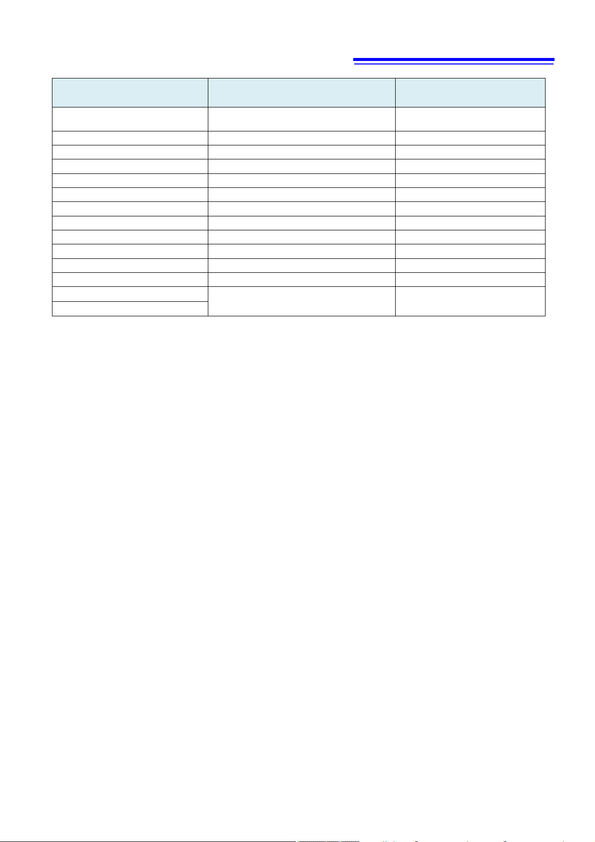
23
<FRTD/RTD/FTH/THER/DEFault>,<Type 2/DEFault>,
(<Measurement value>)
Messages Data Description
[ ]: Omissible [ ]: Omissible, ( ): Response data
:MEASure:TEMPerature?
*PSC <0/1> Clears and reads the power status.
*PSC? (1) Reads the power status.
*CAL? (+0) Executes automatic calibration.
:HCOPy:SDUMp:DATA:FORMat BMP Sets the image data format.
:HCOPy:SDUMp:DATA:FORMat? (BMP) Queries the image data format.
[:SENSe:]VOLTage[:DC]:ZERO:AUTO < 1/0/ON/OFF/ONCE > Sets the auto zero mode.
[:SENSe:]VOLTage[:DC]:ZERO:AUTO? (1) Queries the auto zero mode.
:OUTPut:TRIGger:SLOPe <POSitive/NEGative> Sets the voltmeter complete output signal slope.
:OUTPut:TRIGger:SLOPe? (NEG) Queries the voltmeter complete output signal slope.
:TRIGger:COUNt <Number of measurements/MAX/MIN/DEFault> Sets the number of triggering.
:TRIGger:COUNt? (1) Queries the number of triggering.
:SYSTem:REMote
:SYSTem:RWLock
<Resolution/MAX/MIN/DEFault>
Reads the temperature measurement value.
Sets the remote state.
Page 29
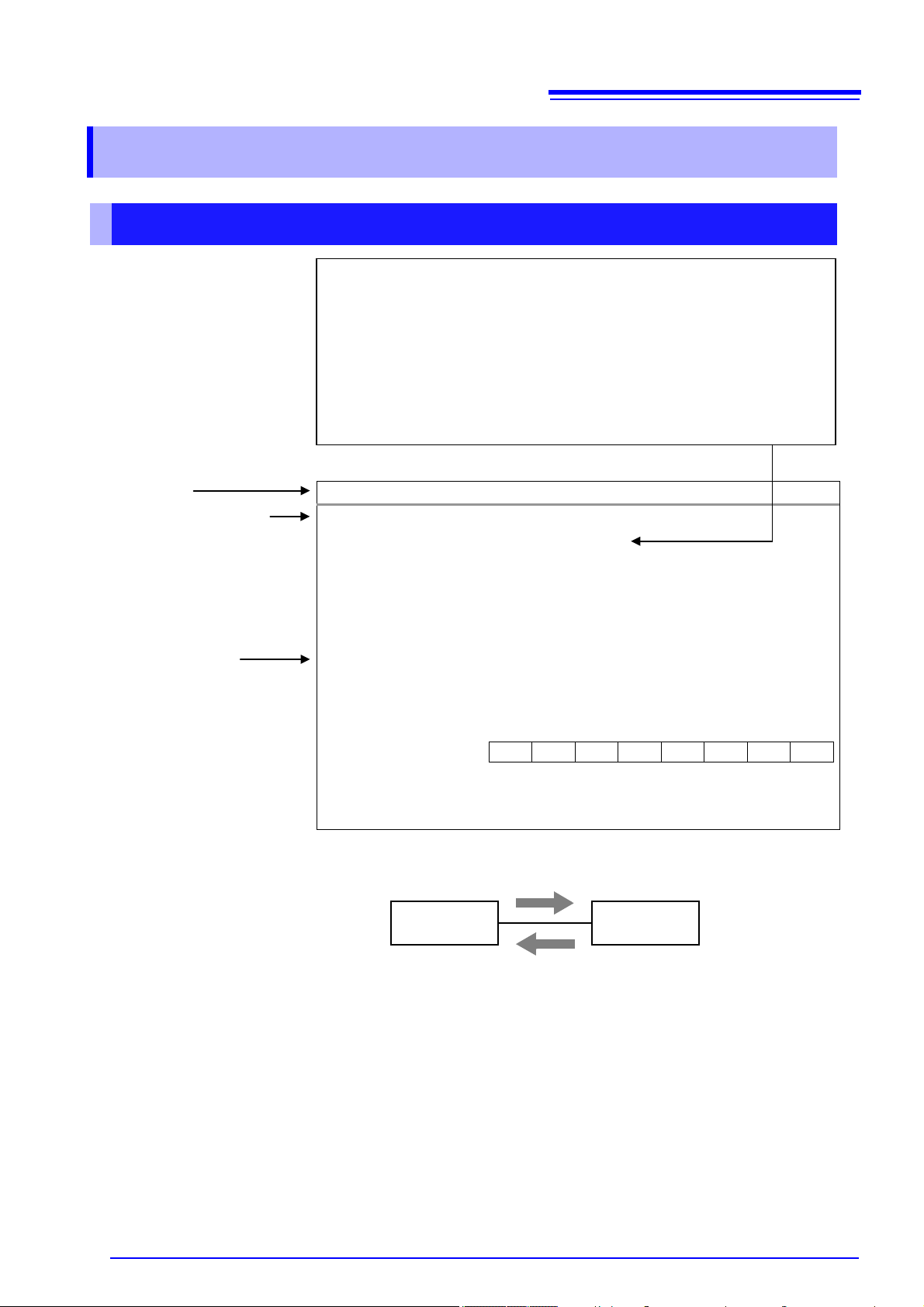
24
Syntax
∗ESE <0 to 255 (NR1)>
Query
∗ESE?
The SESER mask pattern is set to a numerical value
using the *ESE
128
64
32
16 8 4 2 1
bit 7
bit 6
bit 5
bit 4
bit 3
bit 2
bit 1
bit 0
PON
URQ CME EXE DDE QYE
RQC OPC
∗
< >
• NRf
•
•
•
Shows an example of an actual
command application.
Shows the command
escription.
Shows the message syntax.
Explains the command data or
response message.
Describes the message.
Command, Query
Respons
Controller
Instrument
3 Message Reference
Message Reference Interpretation
: Indicates the contents (character or numeric parameters) of the data
portion of a message. Character parameters are returned as all capital
letters.
Numeric Parameters:
Number format may be any of NR1, NR2 and NR3
NR1 Integer data (e.g.: +12, -23, 34)
NR2 Fixed-point data (e.g.: +1.23, -23.45, 3.456)
NR3 Floating-point exponential representation data (e.g.: +1.0E-2, -2.3E+4)
Read/Write the Standard Event Status Enable Register (SESER)
Command
Response <0 to 255 (NR1)>
Description
Example
Command
from 0 to 255. The default value (at power-on) is 0.
Query The contents of the SESER, as set
command, are returned as an NR1 value (0 to 255).
ESE 36
(Sets bit 5 and 2 of SESER.)
Page 30

25
Standard Commands
Query Device ID (Identify Code)
Syntax
Query
*IDN?
Response
<Manufacturer name>,<Model name>,<Serial number>,<Software version>
Example
*IDN?
123456789, software version 1.00. The <Model name> will be
Note
The value returned by : SYSTem:IDNStr can be changed to any character string.
Identify Installed Options
Syntax
Query
*OPT?
Response
<0/GPIB>,<LAN>,<0/RS232C>
Example
• When the GP-IB board is installed
Initialize Device
Syntax
Command
*RST
Description
Resets the instrument to its initial state.
Note
The communications conditions and panel data are not initialized.
Execute Self-test and Query Result
Syntax
Query
*TST?
Response
<PASS/FAIL>
Description
Example
(1) System Data Commands
HIOKI,DM7275-01,123456789,V1.00
The Device ID is HIOKI DM7275-01,
the following.
For DM7275-01: DM7275-01
For DM7275-02: DM7275-02
For DM7275-03: DM7275-03
For DM7276-01: DM7276-01
For DM7276-02: DM7276-02
For DM7276-03: DM7276-03
*OPT?
GPIB,LAN,0
• When the RS-232C board is installed
*OPT?
0,LAN,RS232C
• When the option board is not installed
*OPT?
0,LAN,0
(2) Internal Operation Commands
The Event Status Register is not cleared.
Performs the instrument self-check and returns the result.
Returns PASS when no error occurs and FAIL when an error occurs.
*TST?
FAIL
An error occurred. Correct measurement may not be possible. Request repairs before further use.
Page 31

26
Save Measurement Conditions (Panel Save)
Syntax
Command
*SAV <Panel No.>
<Panel No.> = 1 to 30 (NR1)
Description
Example
Note
panel number to which measurement conditions are already saved is specified, the data
Read Measurement Conditions (Panel Load)
Syntax
Command
*RCL <Panel No.>
<Panel No.> = 1 to 30 (NR1)
Description
Example
Note
not saved is specified, an execution
Request a Sample
Syntax
Command
*TRG
Description
Example
Set OPC Bit of SESR when Finished with All Pending Operations
Syntax
Command
*OPC
Description
when all commands prior to the
Respond with ASCII “1” when Finished with All Pending Operations.
Syntax
Query
*OPC?
Response
1 (NR1)
Description
Responds with ASCII “1” when all commands prior to the *OPC commands have finished processing.
Wait for Pending Commands to Finish
Syntax
Command
*WAI
Description
Saves the current measurement conditions to the specified panel number.
*SAV 1
The current measurement conditions are saved to panel No. 1.
When the a
of the panel number is overwritten with the current measurement conditions.
Reads the measurement conditions saved for the specified panel number.
*RCL 1
The measurement conditions saved for panel No. 1 are read.
When a panel number to which measurement conditions are
error occurs.
Performs one measurement when external triggering (trigger source <EXTERNAL>) is enabled.
It may be necessary to insert wait processing after panel load or range selection. Wait time depends
on Measurement target.
:TRIG:SOUR EXT;*TRG
External triggering is enabled and performs one measurement.
(3) Synchronized Commands
Sets OPC (bit 0) of SESR (Standard Event Status Register) to 1
*OPC command have finished processing.
The instrument waits until all prior commands finish before executing any subsequent commands.
Page 32

27
Clear Event Register and Status Byte Register (Except Output Queue)
Syntax
Command
*CLS
Description
Clears the event status registers. The Status Byte Register bits corresponding to the event status
(Standard Event Status Register, Standard Operation Register, Status
Example
Read/Write the Standard Event Status Enable Register (SESER)
Syntax
Command
*
ESE <0 to 255 (NR1)>
Query
*ESE?
Response
<0 to 255 (NR1)>
Description
The SESER mask pattern is set to a numerical value from 0 to 255. The default value (at
1
128
64
32
16 8 4 2 1
bit 7
bit 6
bit 5
bit 4
bit 3
bit 2
bit 1
bit 0
PON
URQ CME EXE DDE QYE
RQC OPC
Example
Read and Clear Standard Event Status Register (SESR)
Syntax
Query
*ESR?
Response
<0 to 255 (NR1)>
Description
128
64
32
16 8 4 2 1
bit 7
bit 6
bit 5
bit 4
bit 3
bit 2
bit 1
bit 0
128
64
32
16 8 4 2 1
bit 7
bit 6
bit 5
bit 4
bit 3
bit 2
bit 1
bit 0
Example
(4) Status and Event Control Commands
registers are also cleared.
Query Register)
[RS-232C/USB] The output queue is unaffected.
[GP-IB] The output queue, various enable registers, and MAV (bit 4) of the Status Byte
Register are unaffected.
Command
Query
*ESE 36
(Sets bit 5 and 2 of SESER.)
Returns the contents of the SESR as an NR1 value from 0 to 255, and then clears register contents.
power-on) is 0.
The contents of the SESER, as set using the *ESE command, are returned as an NR
value (0 to 255).
[RS-232C/USB]
PON Unused CME EXE DDE QYE Unused OPC
[GP-IB]
PON URQ CME EXE DDE Unused RQC OPC
*ESR?
32
Bit 5 of the SESR has been set to 1.
Page 33

28
Write and Read Service Request Enable Register (SRER)
Syntax
Command
*SRE <0 to 255 (NR1)>
Query
*SRE?
Response
<0 to 255 (NR1)>
Description
Although NRf numerical values are accepted, values to the right of the decimal are
o at
command, are returned as an NR1
128
64
32
16 8 4 2 1
bit 7
bit 6
bit 5
bit 4
bit 3
bit 2
bit 1
bit 0
Standard
Operation
Example
Read Status Byte and MSS Bit
Syntax
Query
*STB?
Response
<0 to 255 (NR1)>
Description
128
64
32
16 8 4 2 1
bit 7
bit 6
bit 5
bit 4
bit 3
bit 2
bit 1
bit 0
Example
Command The SRER mask pattern is set to a numerical value from 0 to 255.
rounded to the nearest integer.
Bit 6 and unused bits (indicated with -) are ignored. The data is initialized to zer
power-on.
Query
The contents of the SRER, as set using the *SRE
value (0 to 255). Bit 6 and unused bits (bit 0 and 1) are always 0.
Status
0 ESB M AV
Register
*SRE
12
Set SRER bits 3 and 2 to 1.
*SRE?
12
SRER bits 3 and 2 have been set to 1.
The contents of the STB are returned as an NR1 value from 0 to 255.
ESB1 MSS ESB MAV ESB0 ERR - -
*STB?
16
STB bit 4 has been set to 1.
Query
Register
System
Error
- -
Page 34

29
Query Condition Register of Standard Operation Register Group
Syntax
Query
:STATus:OPERation:CONDition?
Response
<0 to 16176 (NR1)>
Description
bit15
bit14
bit13
bit12
bit11
bit10
bit9
bit8
RDY
bit7
bit6
bit5
bit4
bit3
bit2
bit1
bit0
_TRG
Example
Note
Query Total Bit Number of Event Register of Standard Operation Register Group
Syntax
Query
:STATus:OPERation[:EVENt]?
Response
<0 to 16176 (NR1)>
Description
bit15
bit14
bit13
bit12
bit11
bit10
bit9
bit8
_RDY
bit7
bit6
bit5
bit4
bit3
bit2
bit1
bit0
_TRG
Example
Note
•
Device-Specific Commands
(1) Event Status Register
See the following for a relationship with the Status Byte Register.
• Status Byte Register (p.6)
• Event Register (p.8)
- - ERR HOLD EOM LOCK
- -
:STAT:OPER:COND?
1024
The instrument is in the remote state.
•
The latest status is returned when this command is received.
•
Unlike :STATus:OPERation:EVENt?, :STATus:OPERation?, bit information is not held.
WAIT
MEAS - - - -
MEM_
SET
- - ERR HOLD EOM LOCK
- -
WAIT
MEAS - - - -
MEM
SET
:STAT:OPER?
1024
This instrument has been in the remote state.
When an event occurs, 1 is set for the bit corresponding to each event.
•
Until * CLS or this query is executed or the power is turned on again, the bit is not cleared.
Page 35

30
Query Enable Register of Standard Operation Register Group
Syntax
Command
:STATus:OPERation:ENABle <0 to 65,535 (NR1)>
Query
:STATus:OPERation:ENABle?
Response
<0 to 16177 (NR1)>
Description
bit15
bit14
bit13
bit12
bit11
bit10
bit9
bit8
_RDY
bit7
bit6
bit5
bit4
bit3
bit2
bit1
bit0
_TRG
Note
) are set to 1, the command is accepted but is not reflected in the
Query Total Bit Number of Condition Register of Status Query Register Group
Syntax
Query
:STATus:QUEStionable:CONDition?
Response
<0 to 63497 (NR1)>
Description
bit15
bit14
bit13
bit12
bit11
bit10
bit9
bit8
ERR
OVR
bit7
bit6
bit5
bit4
bit3
bit2
bit1
bit0 - - - - - - - -
Example
Note
Query Event Register of Status Query Register Group
Syntax
Query
:STATus:QUEStionable[:EVENt]?
Response
<0 to 63497 (NR1)>
Description
bit15
bit14
bit13
bit12
bit11
bit10
bit9
bit8
ERR
OVR
bit7
bit6
bit5
bit4
bit3
bit2
bit1
bit0
OVR
OVR
Example
Note
is query is executed
- - ERR HOLD EOM LOCK
MEM
SET
- -
•
The data is initialized to 0 at power-on.
•
When unused bits (indicated with -
WAIT
MEAS - - - RSV
query result.
CNT_
:STAT:QUES:COND?
32768
A contact error occurs.
MEM_
OB HI LO - - -
•
The latest status is returned when this command is received.
•
Unlike :STATus:QUEStonable:EVENt?, :STATus:QUEStonable?, bit information is not held.
CNT_
MEM_
OB HI LO - - -
- - - -
TMP_
- -
VLT_
:STAT:QUES?
1
An out-of-range error has occurred at voltage measurement of the instrument.
When an event occurs, 1 is set for the bit corresponding to each event. *CLS or th
or the power is turned on again, the bit is not cleared.
Page 36

31
Set and Query Enable Register of Status Query Register Group
Syntax
Command
:STATus:QUEStionable:ENABle <0 to 65535 (NR1)>
Query
:STATus:QUEStionable:ENABle?
Response
<0 to 63775 (NR1)>
Description
bit15
bit14
bit13
bit12
bit11
bit10
bit9
bit8
ERR
OVR
bit7
bit6
bit5
bit4
bit3
bit2
bit1
bit0
OVR
OVR
Note
) are set to 1, the command is accepted but is not reflected in the
CNT_
- - - RSV
•
The data is initialized to zero at power-on.
•
When unused bits (indicated with -
query result.
MEM_
OB HI LO - - RSV
TMP_
RSV RSV
VLT_
Page 37

32
Measurement Range
Measured Value
±OvrRng
Measurement Fault
100 mV
± □□□.□□□□□E-03
±990.00000E+35
+991.00000E+35
1 V ± □□□□.□□□□E-03
±9900.0000E+34
+9910.0000E+34
10 V ± □□.□□□□□□E+00
±99.000000E+36
+99.100000E+36
100 V
± □□□.□□□□□E+00
±990.00000E+35
+991.00000E+35
1000 V
± □□□□.□□□□E+00
±9900.0000E+34
+9910.0000E+34
Measured Value
±OvrRng
Measurement Fault
± □.□□□□□□□□E±0□
±9.90000000E+37
+9.91000000E+37
Measured Value
±OvrRng
Measurement Fault
± □□.□□
±9.900E+37
+9.910E+37
Measured Value
±OvrRng
Measurement Fault
± □.□□□□□□□□E±0□
±9.90000000E+37
+9.91000000E+37
Measured Value
±OvrRng
Measurement Fault
± □□.□□
±9.900E+37
+9.910E+37
(2) Reading Measurment Values
Measurement Value Formats
(a) :FETCh?, :READ?, MEASure[:VOLTage]:DC? response
• Voltage: Unit V (When :SYSTem:COMMunicate:FORMat FIX is set)
Note:•Position of the decimal point and exponent is changed by setting of the scalling.
Please refer to instruction manual of the instruments about the scalling.
•
When the number of digits for the integer is short, 0 is entered.
Example) When the measurement value is 1 V in 1000 V range, the measurement value is
presented as +0001.0000E+00.
•The mantissa changes depending on the setting number of digits.
• Voltage: Unit V (When :SYSTem:COMMunicate:FORMat FLOAT is set)
Note: The measured value is presented as a floating-point value with eight decimal places.
• Temperature: Unit °C (
:FETCh? TEMPerature, READ? TEMPerature
)
Time to receive measured value is different for the :FETCh? and :READ?/MEAS:DC? commands
See: Data Exporting Methods (p.71), Triggering (p.40)
(b) :DATA:LAST? response
• Voltage: Unit V
Note: The measurement value is presented as a floating-point value with eight decimal
places.
(d) :MEASure:TEMPerature? response
• Temperature: Unit °C
Page 38

33
Read Most Recent Measurement
Syntax
Query
:FETCh? [TEMPerature]
(1) When TEMPerature parameter is not specified
See: “Measurement Value Formats” (p.32)
Description
•
Example
:TRIG:SOUR EXT
E-02,+23.87
Note
• If a measurement has not been performed (the memory is empty), an execution error occurs.
is the number
of data stored in the memory. (MAX:5000 data)
Response
•
When :SYST:COMM:FORM FIX is set
<Voltage measurement value>
•
When :SYST:COMM:FORM FLOAT is set
<Volatage measurement value 1>, <Voltage measurement value 2>, ..., <Voltage
measurement value n>
Note: The measured values are output in the order that they are received.
(2) When TEMPerature parameter is specified
•
When :SYST:COMM:FORM FIX is set
<Voltage Measurement value>, <Temperature measurement value>
•
When :SYST:COMM:FORM FLOAT is set
<Voltage measurement value 1>, <Temperature measurement value1>, <Voltage
measurement value 2>, <Temperature measurement value2>,...,<Voltage
measurement value n>, <Temperature measurement value n>
Note: The measured values are output in the order that they are received.
When :SYST:COMM:FORM FIX is set
Reads the most recent measurement. No trigger occurs.
•
When :SYST:COMM:FORM FLOAT is set
Reads the most recent measurement for the number of data stored in the memory. No trigger
occurs.
See: Data Exporting Methods (p.71), Triggering (p.40)
:SYST:COMM:FORM FIX;:SAMP:COUN 4
:INIT
*TRG
:FETC?
+094.31342E-03
:INIT
*TRG
:FETC?
+094.30276E-03
:FETC? TEMP
+094.30276E-03,+23.87
:SYST:COMM:FORM FLOAT
:INIT
*TRG
:FETC?
+9.46651535E-02,+9.44042868E-02,+9.42089137E-02,+9.42364743E-02
:INIT
*TRG
:FETC?
+9.46651535E-02,+9.44042868E-02,+9.42089137E-02,+9.42364743E-02,+9.46651536E-02,+9.44
042867E-02,+9.42089132E-02,+9.42364741E-02
:FETC? TEMP
+9.46651535E-02,+23.80,+9.44042868E-02,+23.81,+9.42089137E-02,+23.82,+9.42364743E-02,+
23.83,+9.46651536E-02,+23.84,+9.44042867E-02,+23.85,+9.42089132E-02,+23.86,+9.42364741
• When :SYST:COMM:FORM FLOAT is set, the number of returned measurement data
Page 39

34
Measurement (waits for trigger and reads the measured values)
Syntax
Query
:READ?
[TEMPerature]
(1) When TEMPerature parameter is not specified
See: “Measurement Value Formats” (p.32)
Description
• When :SYST:COMM:FORM FIX is set
Trigger Source
Operation
IMMediate
Triggers and reads the measured value.
Triggers by TRIG signal input, and continuously reads the measurement
values.
Example
Note
enabled and the command is sent. With GP-IB, after the command is sent and then after allowing a
Response
•
When :SYST:COMM:FORM FIX is set
<Voltage Measurement value>
•
When :SYST:COMM:FORM FLOAT is set
<Volatage Measurement value 1>, <Voltage Measurement value 2>, ..., <Voltage
Measurement value n>
Note: The measured values are output in the order that they are received.
(2) When TEMPerature parameter is specified
•
When :SYST:COMM:FORM FIX is set
<Voltage Measurement value>, <Temperature Measurement value>
•
When :SYST:COMM:FORM FLOAT is set
<Voltage Measurement value 1>, <Temperature Measurement value1>, <Voltage
Measurement value 2>, <Temperature Measurement value2>,...,<Voltage
Measurement value N>, < Temperature Measurement value N>
Note: The measured values are output in the order that they are received.
Switches from the Idle State to the Trigger Wait State, and then reads the measurement value after
the measurement is completed.
• When :SYST:COMM:FORM FLOAT is set
Switches from the Idle State to the Trigger Wait State, and then reads the measurement value for N
times of sampling after the measurement is completed.
With the auto range enabled, the most suitable range is selected before measurement.
See: Data Exporting Methods (p.71), Triggering (p.40)
EXTernal
:TRIG:SOUR EXT
:SYST:COMM:FORM FIX;:SAMP:COUN 4
:READ?
*TRG
+094.31342E-03
:READ? TEMP
*TRG
+094.31343E-03,+23.87
:SYST:COMM:FORM FLOAT
:READ?
*TRG
+9.46651535E-02,+9.44042868E-02,+9.42089137E-02,+9.42364743E-02
:READ? TEMP
*TRG
+9.46651534E-02,+23.84,+9.44042867E-02,+23.85,+9.42089136E-02,+23.86,+9.42364742E-02,+
23.87
• Automatically switches to :INITiate:CONTinuous OFF after receiving this message.
• The next command does not execute until measurement is finished. *TRG and :ABORt are
received.
• If a trigger is input with the *TRG command, an external trigger (trigger source <EXTERNAL>) is
Page 40

35
the measurement value’s response will be
epends
Measure Voltage with Measurement Range Specified
Syntax
Query
:MEASure[:VOLTage]:DC?
<Range/AUTO/MAX/MIN/DEFault >
<Measurement value>
See: “Measurement Value Formats” (p.32)
<Measurement range> = 100 mV/1 V/10 V/100 V/1000 V/Voltage to be measured
Note: V may be omitted.
Description
Performs measurement with the measurement range and reads the most recent measurement.
Example
:SYST:COMM:FORM FIX
Note
• Automatically resets the measurement related settings after receiving this message, and then
Read Temperature Measurement Value
Syntax
Query
:MEASure:TEMPerature?
<Temperature measurement value>
See: “Measurement Value Formats” (p.32)
Description
Example
:MEAS:TEMP?
Note
• Automatically resets the measurement related settings after receiving this message, and then
wait time corresponding to the sampling time, specify the talker.
• With an external trigger (trigger source <EXTERNAL>),
doubled when the data output function is ON. When using, switch the data output function OFF.
• It may be necessary to insert wait processing after panel load or range selection. Wait time d
on Measurement target.
Response
(MAX: 1000 V, MIN: 100 mV, DEFault: AUTO)
:MEAS:DC?
+0.00201E-03
:SYST:COMM:FORM FLOAT
:MEAS:DC?
+2.01462719E-06
switches to :INITiate:CONTinuous OFF and turns the temperature display OFF.
• The measurement range may be omitted.
• When the range is switched to 100 mV, it takes approximately 700 ms to respond as internal
calibration is performed.
When the measurement range is omitted, DEFault is set.
Response
Performs voltage and temperature measurement and reads the temperature measurement value.
+25.46
switches to :INITiate:CONTinuous OFF, and turns the temperature display ON.
• The temperature is updated along with the voltage.
•
For details of compatibility with the products of other manufacturers, see “Commands Compatible
with the Products of Other Manufacturers” (
p.
68
).
Page 41

36
Read the most recent measurement
Syntax
Query
:DATA:LAST?
[TEMPerature]
• When TEMPerature parameter is not specified
See: “Measurement Value Formats” (p.24)
Description
Reads the most recent measurement. No trigger occurs.
Example
:DATA:LAST?
Note
If a measurement has not been performed, the value for a measurement fault is returned.
Abort Measurement
Syntax
Query
:ABORt
Description
Aborts :READ.
And the judgment is cleared by :ABORT.
Example
:READ?
Set and Query Measurement Output Format
Syntax
Command
:SYSTem:COMMunicate:FORMat < FIX/FLOAT >
Query
:SYSTem:COMMunicate:FORMat?
Response
< FIX/FLOAT >
Description
The operations for the result of FETCh?, READ?, MEASure[:VOLTage]:DC? are as follows.
Note
The operation when the instrument switches from the local state to the remote state varies depending
Response
<Voltage Measurement value>
• When TEMPerature parameter is specified
<Voltage Measurement value>,<Temperature Measurement value>
See: Data Exporting Methods (p.71), Triggering (p.40)
+5.48260994E-03
:DATA:LAST? TEMP
+5.48260994E-03,+23.87
:ABOR
Executes an abort.
FIX: Reads only the most recent measurement with the number of digits same as that displayed in
the screen.
FLOAT:
with eight decimal places.
See: “Measurement Value Formats” (p.32)
on the settings.
FIX: The measurement state remains in the local state.
FLOAT: The measurement state is in the STOP state.
Reads the measurement values for the number of sampling data as a floating-point value
Page 42

37
Execute Self-test and Query Result
Syntax
Query
:TEST:ALL?
Response
< PASS/FAIL >
Example
:TEST:ALL?
Note
Same operation as *TST?
Set and Query System Date
Syntax
Command
:S YS Tem: D ATE <Year>,<Month>,<Day>
Query
:SYSTem:DATE?
Response
<Year>,<Month>,<Day>
<Day> = 01 to 31 [Day]
Description
Example
Note
Set and Query System Time
Syntax
Command
:SYSTem:TIME <Hour>,<Minute>,<Second>
Query
:SYSTem:TIME?
Response
<Hour>,<Minute>,<Second>
<Hour> = 00 to 23 [Hour]
<Second> = 00 to 59 [Second]
Description
Sets the time of the real-time system clock.
Example
:SYST:TIME 8,25,0
Note
Attempting to set an out-of-range numerical value returns an execution error. Attempting to set an
(3) Self-Test
(4) Clock
PASS
<Year> = 00 to 99 [Year]
<Month> = 01 to 12 [Month]
Sets the date of the real-time system clock.
:SYST:DATE 15,9,2
Set the date to September 2, 2015.
:SYST:DATE?
15,9,2
The date is September 2, 2015.
Attempting to set an out-of-range numerical value returns an execution error. Attempting to set an
non-existent date (such as 13,06,31) returns an execution error.
<Minute> = 00 to 59 [Minute]
Set the time to 8:25 and 00 seconds.
:SYST:TIME?
23,9,53
The time is 23:9 and 53 seconds.
non-existent time (such as 9,6,71) returns an execution error.
Page 43

38
Set and Query Measurement Range
Syntax
Command
[:SENSe:]VOLTage:DC:RANGe <Measurement range/MAX/MIN/DEFault>
Query
[:SENSe:]VOLTage:DC:RANGe?
Response
<Measurement range>
+1.00000000E+02/ +1.00000000E+03
Example
Note
Set and Query Measurement Auto Range
Syntax
Command
[:SENSe:]VOLTage:DC:RANGe:AUTO < 1/0/ON/OFF >
Query
[:SENSe:]VOLTage:DC:RANGe:AUTO?
Response
< 1/0 >
Example
Set and Query Measurement Function
Syntax
Command
[:SENSe:]FUNCtion[:ON] < TEMPerature/VOLTage[:DC] >
Query
[:SENSe:]FUNCtion[:ON]?
Response
”VOLT
:DC”
Example
Note
(5) Measurement Range
Command
<Measurement range> = 100 mV/1 V/10 V/100 V/1000 V/Voltage to be measured
(MAX: 1000 V, MIN: 100 mV, DEFault:1000 V)
Note: V may be omitted.
Query
<Measurement range> = +1.00000000E-01/+1.00000000E+00/+1.00000000E+01/
VOLT:DC:RANG 100mV
VOLT:DC:RANG?
+1.00000000E-01
• When the measurement range is set using the command, the instrument is set to the most suitable
range for measuring the given voltage if the voltage to be measured is used as an argument.
Example
VOLT:DC:RANG 6V
VOLT:DC:RANG?
+1.00000000E+01
• The query result with the auto range enabled becomes the range selected by the measurement
system.
VOLT:DC:RANG:AUTO OFF
VOLT:DC:RANG:AUTO?
0
(6) Measurement Function
TEMPerature = Displays the voltage measurement value and temperature measurement value.
VOLTage[:DC] = Displays only the voltage measurement value.
FUNC TEMP
FUNC?
”VOLT:DC”
The query result is “VOLT:DC” (fixed).
Page 44

39
Set and Query Integral Time(PLC)
Syntax
[:SENSe:]VOLTage[:DC]:NPLCycles
SLOW /MEDium/ FAST >
Query
[:SENSe:]VOLTage[:DC]:NPLCycles?
Response
< Integral time(PLC) >
Speed
Integral time [PLC]
SLOW
100
MEDium
10
FAST
1
Example
:VOLT:NPLC 0.02
Set and Query Integral Time(sec) Enabled
Syntax
Command
[:SENSe:]VOLTage[:DC]:APERture:ENABled < 1/0/ON/OFF >
Query
[:SENSe:]VOLTage[:DC]:APERture:ENABled?
Response
< 1/0 >
Description
Command
Example
:VOLT:APER:ENAB ON
Set and Query Integral Time(sec)
Syntax
Command
[:SENSe:]VOLTage[:DC]:APERture < Integral time(sec) /MAX/MIN/DEFault >
Query
[:SENSe:]VOLTage[:DC]:APERture?
Response
< Integral time(sec) >
Example
(7) Measurement Speed
Command
< integral time(PLC) > = 0.02 to 100 [PLC]
(MAX: 100, MIN: 0.02, DEFault: 10)
The integral time for each speed is as follows.
:VOLT:NPLC?
+2.00000000E-02
:VOLT:NPLC FAST
:VOLT:NPLC?
+1.00000000E+00
< Integral time(PLC)/MAX/MIN/DEFault/
Sets the function for performing measurement with the integral time(sec) specified.
Query
Queries the function for performing measurement with the integral time(sec) specified.
:VOLT:APER:ENAB?
1
< Integral time(sec) > = 0.001 to 9.999 [sec]
(MAX: 9.999, MIN: 0.001, DEFault: 1
:VOLT:APER 2
:VOLT:APER?
+2.00000000E+00
Page 45

40
Measurement
Continuous Measurement Command-Specific Settings
:INITIATE:CONTINUOUS ON
:INITIATE:CONTINUOUS OFF
Trigger Delay
Measurement
Calculation
Measurement Value Output
Contact Check
Trigger Delay
Measurement
Calculation
Measurement Value Output
Idle State
:INITIATE:IMMEDIATE
or :READ?
Contact Check
N = Based on :SAMPLE:COUNT setting.
The internal memory for
storing measurement
values is cleared.
Repeated
N times.
Trigger Delay
Measurement
Calculation
Measurement Value
Output
Trigger Wait State
TRIG signal, [TRIG] key,
or *TRG
Contact Check
N = Based on the :SAMPLE:COUNT setting.
Repeated
N times.
Trigger Delay
Measurement
Calculation
Measurement Value
Output
Trigger Wait State
TRIG signal, [TRIG] key,
or *TRG
Idle State
:INITIATE:IMMEDIATE
or :READ?
Contact Check
N = Based on the :SAMPLE:COUNT setting.
The internal memory for
storing measurement
values is cleared.
Repeated
N times.
If this has been set to OFF, when operation is returned to the Local state or the power is turned off and then back
Exporting measured values: “Data Exporting Methods” (p.71)
(8) Triggering
Relationship between Trigger Source and Continuous Measurement Operation
Operation depends on continuous measurement setting (
setting (
:TRIGGER:SOURCE) (p.41) as follows. See: “4. Data Exporting Methods” (p.71)
:INITIATE:CONTINUOUS) (p.41) and the trigger source
Flow
Free-Run state. Measurement continues
automatically.
Trigger by :INITIATE (or :READ?) command.
[STOP state]
[RUN state]
:TRIGGER:SOURCE IMM
Trigger by TRIG signal, [TRIG] key, or *TRG
command.
After measurement, enters the trigger wait
state.
[EXT state]
Trigger Source
Issue :INITIATE (or :READ?) command to
wait for trigger.
Trigger by TRIG signal, [TRIG] key or *TRG.
[EXT STOP state]
:TRIGGER:SOURCE EXT
The :INITIATE:CONTINUOUS OFF state can only be set by Remote command.
The :INITIATE:CONTINUOUS OFF
on, the :INITIATE:CONTINUOUS ON state occurs.
See: “Return to Local Control” (p.58)
state can only be set by Remote command.
Page 46

41
Set and Query Continuous Measurement
Syntax
Command
:INITiate:CONTinuous < 1/0/ON/OFF >
Query
:INITiate:CONTinuous?
Response
< 1/0 >
<ON> = Continuous Measurement Enabled
Description
• Continuous Measurement Enabled ([RUN state] and [EXT state]):
Example
:INIT:CONT OFF
Set Trigger Wait
Syntax
Command
:INITiate[:IMMediate]
Description
Example
Note
Set and Query Trigger Source
Syntax
Command
:TRIGger:SOURce < IMMediate/ EXTernal/BUS >
Query
:TRIGger:SOURce?
Response
< IMM/ EXT >
<IMMediate> = Internal triggering
Example
:TRIG:SOUR IMM
Note
EXT is set when BUS is set using the remote command.
<OFF> = Continuous Measurement Disabled
After measurement, enters the Trigger Wait State. When there is an internal trigger (trigger source
<IMMEDIATE>), the next trigger is promptly generated and enters a free-run state.
• Continuous Measurement Disabled ([STOP state] and [EXT STOP state]):
After measurement, enters the Idle State instead of the Trigger Wait State.
• Triggering is ignored in the Idle State. Executing :INITiate[:IMMediate]
State.
• Continuous measurement is enabled upon exiting from the Remote State.
:INIT:CONT?
0
enables the Trigger Wait
Switches triggering from the Idle State to the Trigger Wait State.
The measurement value storage memory is cleared.
Disable continuous measurement, and read one value for each trigger event.
Sending
:TRIG:SOUR IMM ...... Triggers immediately when entering the Trigger Wait State.
:INIT:CONT OFF ......... Disables continuous measurement.
:INIT ........................... Enables Trigger Wait. Triggers immediately upon: TRIG:SOUR IMM.
• Automatically switches to :INITiate:CONTinuous OFF after receiving this message.
• When there is an internal trigger (trigger source <IMMEDIATE>), triggering promptly occurs and
enters the idle state.
• When there is an external trigger (trigger source <EXTERNAL>), the external trigger wait state is
entered.
When a trigger is received, a single measurement is performed and enters the idle state.
<EXTernal> = External triggering
<BUS> = External triggering
:TRIG:SOUR?
IMM
Page 47

42
Set and Query Number of Measurements
Syntax
Command
:SAMPle:COUNt <Number of measurements/MAX/MIN/DEFault>
Query
:SAMPle:COUNt?
Response
<Number of measurements>
<Number of measurements> = 1 to 5000
Example
:SAMP:COUN 500
Set and Query Trigger Delay
Syntax
Command
:TRIGger:DELay <Delay time/MAX/MIN/DEFault>
Query
:TRIGger:DELay?
Response
<Delay time>
<Delay time> = 0 to 9.999 [sec]
(MAX: 9.999, MIN: 0, DEFault: 0)
Example
:TRIG:DEL 1
Set and Query Trigger Preset Delay
Syntax
Command
:TRIGger:DELay:AUTO <1/0/ON/OFF >
Query
:TRIGger:DELay:AUTO?
Response
< 1/0 >
Example
:TRIG:DEL:AUTO ON
(MAX: 5000, MIN: 1, DEFault: 1)
:SAMP:COUN?
500
:TRIG:DEL?
+1.00000000E+00
:TRIG:DEL:AUTO?
1
Page 48

43
Set and Query Voltage Measurement Value’s Number of Digits
Syntax
Command
[:SENSe:]VOLTage:DIGits <Number of digits/MAX/MIN/DEFault>
Query
[:SENSe:]VOLTage:DIGits?
Response
<Number of digits>
Number of Digits
Screen Setting
8
7.5 7 6.5 6 5.5 5 4.5 4 3.5
Example
:VOLT:DIG 8
Set and Query Label Display Function
Syntax
Command
:SYSTem:LABel: STATe < 1/0/ON/OFF >
Query
:SYSTem:LABel: STATe?
Response
< 1/0 >
Example
SYST:LAB:STAT ON
1
Set and Query Label Name
Syntax
Command
:SYSTem:LABel < Label name >
Query
:SYSTem:LABel?
Response
< Label name >
< Label name > = “String with maximum of 8 characters”
Example
Note
(9) Setting Number of Digits
<Number of digits> = 4 to 8
(MAX: 8, MIN: 4, DEFault: 8)
:VOLT:DIG?
8
(10) Label Display
SYST:LAB:STAT?
SYST:LAB “LAVEL_00”
SYST:LAB?
“LAVEL_00”
• Specify only the characters that can be used for the instrument.
• When a label name is specified by the :SYSTem:LABel command, the label display function is
forcefully turned ON.
• When a query is executed with the label display function OFF, OFF is returned.
Page 49

44
Execute and Query Comparator
Syntax
Command
:CALCulate:LIMit[:STATe] < 1/0/ON/OFF >
Query
:CALCulate:LIMit[:STATe]?
Response
< 1/0 >
Example
Note
Set and Query Buzzer
Syntax
Command
:CALCulate:LIMit:BEEPer <Condition>,<Type>,<Count>
Query
:CALCulate:LIMit:BEEPer? <Condition>
Response
<Condition>,<Type>,<Count>
<Condition> = HI/ IN /LO
<Count> = 0: Continuous, 1 to 5: Count [times]
Example
:CALC:LIM:BEEP IN,1,0
Note
Count of the parameter is omissible. When Count is omitted, it is not set.
Set and Query Absolute Value Judgment Function
Syntax
Command
:CALCulate:LIMit:ABSolute <1/0/ON/OFF >
Query
:CALCulate:LIMit:ABSolute?
Response
< 1/0 >
Example
Set and Query Upper Threshold Value Enabled
Syntax
Command
:CALCulate:LIMit:UPPer:ENABle <1/0/ON/OFF >
Query
:CALCulate:LIMit:UPPer:ENABle?
Response
< 1/0 >
Example
:CALC:LIM:UPP:ENAB ON
1
Set and Query Upper Threshold Values
Syntax
Command
:CALCulate:LIMit:UPPer[:DATA] <Upper threshold>
Query
:CALCulate:LIMit:UPPer[:DATA]?
Response
<Upper threshold>
<Upper threshold> = -1.0E+03 to +1.0E+03 (NRf) [V]
Example
(11) Comparator
When making comparator settings by commands, the measurement range is not automatically selected.
:CALC:LIM:STAT ON
:CALC:LIM:STAT?
1
When the comparator is executed, the BIN function enters the OFF state.
<Type> = 0: Buzzer OFF, 1 to 3: Type 1 to 3
:CALC:LIM:BEEP? IN
IN,1,0
:CALC:LIM:ABS ON
:CALC:LIM:ABS?
1
:CALC:LIM:UPP:ENAB?
:CALC:LIM:UPP 1.0
:CALC:LIM:UPP?
+1.00000000E+00
The upper threshold is 1.0 V.
Page 50

45
Set and Query Lower Threshold Value Enabled
Syntax
Command
:CALCulate:LIMit:LOWer:ENABle <1/0/ON/OFF >
Query
:CALCulate:LIMit:LOWer:ENABle?
Response
< 1/0 >
Example
:CALC:LIM:LOW:ENAB ON
Set and Query Lower Threshold Values
Syntax
Command
:CALCulate:LIMit:LOWer[:DATA] < Lower threshold >
Query
:CALCulate:LIMit:LOWer[:DATA]?
Response
< Lower threshold >
<Lower threshold> = -1.0E+03 to +1.0E+03 (NRf) [V]
Example
Set and Query Comparator Judgment Continuous Function
Syntax
Command
:CALCulate:LIMit:DELay <1/0/ON/OFF >
Query
:CALCulate:LIMit:DELay?
Response
< 1/0 >
Example
:CALC:LIM:DEL ON
Set and Query Comparator Judgment Continuous Count
Syntax
Command
:CALCulate:LIMit:DELay:COUNt <Count>
Query
:CALCulate:LIMit:DELay:COUNt?
Response
<Count>
<Count> = 2 to 10 (NR1)
Example
Clear Comparator Event Status Register
Syntax
Command
:CALCulate:LIMit:CLEar[:IMMediate]
Description
Clears the comparator and BIN function-related Status Query Register bits (bit 11, bit 12 and bit13).
Query the Comparator Result
Syntax
Query
:CALCulate:LIMit:RESult?
Response
<HI/IN/LO/ERR/OFF>
Example
Note
hen there are no measurement values, the response is ERR.
:CALC:LIM:LOW:ENAB?
1
:CALC:LIM:LOW 0.9
:CALC:LIM:LOW?
+9.00000000E-01
The lower threshold is 0.9 V.
Sets the comparator judgment continuous function to ON.
:CALC:LIM:DEL:COUN 10
Sets the comparator judgment continuous count to 10 times.
:CALC:LIM:RES?
IN
The comparator reslt is IN.
W
Page 51

46
Execute and Query BIN Measurement
Syntax
Command
:CALCulate:BIN[:STATe] < 1/0/ON/OFF >
Query
:CALCulate:BIN[:STATe]?
Response
< 1/0 >
Example
Note
Set and Query Enabled Pattern
Syntax
Command
:CALCulate:BIN:ENABle <Enabled pattern>
Query
:CALCulate:BIN:ENABle?
<Enabled pattern> = 0 to 1023 (Decimal digit) (NR1)
512
256
128
64
32
16 8 4 2 1
bit9
bit8
bit7
bit6
bit5
bit4
bit3
bit2
bit1
bit0
BIN9
BIN8
BIN7
BIN6
BIN5
BIN4
BIN3
BIN2
BIN1
BIN0
Example
:CALC:BIN:ENAB 15
Set and Query Upper Threshold Values
Syntax
Command
:CALCulate:BIN:UPPer < BIN No. >,< Upper threshold >
Query
:CALCulate:BIN:UPPer? < BIN No. >
Response
<Upper threshold>
Example
Set and Query Lower Threshold Values
Syntax
Command
:CALCulate:BIN:LOWer < BIN No. >,< Lower threshold >
Query
:CALCulate:BIN:LOWer? < BIN No. >
Response
< Lower threshold >
Example
(12) BIN
:CALC:BIN:STAT ON
:CALC:BIN:STAT?
1
When the BIN function is executed, the comparator function switches to OFF.
Response
“1” will be the BIN number bit used to execute the BIN measurement.
BIN0 to BIN3 can be used.
< BIN No.> = 0 to 9 (NR1)
<Upper threshold> = -1.0E+03 to +1.0E+03 (NRf) [V]
:CALC:BIN:UPPer 0,1.0
The upper threshold for BIN0 is 1. 0 V.
< BIN No.> = 0 to 9 (NR1)
<Lower threshold> = -1.0E+03 to +1.0E+03 (NRf) [V]
:CALC:BIN:LOW 0,0.9
The lower threshold for BIN0 is 0.9 V.
Page 52

47
Query BIN Judgment Result
Syntax
Query
:CALCulate:BIN:RESult?
<NR1>
bit10
bit9
bit8
bit7
bit6
bit5
OB
BIN9
BIN8
BIN7
BIN6
BIN5
bit4
bit3
bit2
bit1
bit0
BIN4
BIN3
BIN2
BIN1
BIN0
Example
Save and Read Measurement Conditions
Syntax
*S AV
*RCL <Panel No.>
Note
Delete Panel
Syntax
Command
:SYSTem:PANel:CLEar <Panel No.>
Set and Query Panel Name
Syntax
:SYSTem:PAN el:NAM E
Maximum 10 characters)>
Query
:SYSTem:PANel:NAME? <Panel No.>
Response
<Panel No.>,<Panel name (Character string data: Maximum 10 characters)>
Example
Note
Query Date of Saving Panel
Syntax
Command
:SYSTem:PAN el:DATE ? <Panel No.>
<Year, Month, Day, Hour, Minute, Second>
<Panel No.> = 1 to 30 (NR1)
Example
:SYST:PAN:DATE? 1
Note
When the panel that is not saved is specified, an execution error occurs.
Response
<NR1> = 0 to 1024
“1” will be the BIN number bit for the PASS with BIN measurement.
:CALC:BIN:RES?
128
BIN7 is PASS.
(13) Saving and Reading Measurement Conditions
Command
For details, check the *S AV and *RCL common commands.
<Panel No.>
<Panel No.> = 1 to 30 (NR1)
Command
<Panel No.> = 1 to 30 (NR1)
For information on character string data, see Data Formats. (p.4)
:SYST:PAN:NAME 1, "PANEL_1"
:SYST:PAN:NAME? 1
1,“PANEL_1”
When the panel that is not saved is specified, an execution error occurs.
<Panel No.>,<Panel name (Character string data:
Response
15,10,31,23,1,2
Page 53

48
Save Setting File to USB Flash Drive
Syntax
Command
:MMEMory:STORe:STATe <File name> [,ALL]
Example
:MMEM:STOR:STAT "ALL_000", ALL
Note
M:STOR:STAT <File name>, ALL, all setting
Read Setting File from USB Flash Drive
Syntax
Command
:MMEMory:LOAD:STATe <File name>
Example
:MMEM:LOAD:STAT “SET_000” * Loads SET_000.SET.
Note
• The command is accepted if a file name is specified with a file extension included or excluded.
extension
Set and Query Function for Reading Panel at Startup
Syntax
Command
:MMEMory:STATe:RECall:AUTO < 1/0/ON/OFF >
Query
:MMEMory:STATe:RECall:AUTO?
Response
< 1/0 >
Example
Set and Query Panel No. to be Read at Startup
Syntax
Command
:MMEMory:STATe:RECall:SELect <Panel No.>
Query
:MMEMory:STATe:RECall:SELect?
Response
<Panel No.>
<Panel No.> = 0 to 30 (NR1)
1 to 30: Loads the panel settings.
Example
:MMEM:STAT:REC:SEL 5
:MMEM:STOR:STAT "SET_000.SET"
:MMEM:STOR:STAT "SET_000"
:MMEM:STOR:STAT "ALL_000.ALL", ALL
• When ALL is attached to the end of data, such as :MME
data including panel data is saved to a file.
• The command is accepted if a file name is specified with a file extension included or excluded.
• If a file name extension is omitted, the following operations are performed.
:MMEM:STOR:STAT “SET_000” ··········· : Saves with file name “SET_000.SET”.
:MMEM:STOR:STAT “ALL_000”, ALL ····· : Saves with file name “ALL_000.ALL”.
• Up to 12 characters can be used including a file name extension (.xxx) for a file name. (8 or less
characters if a file name extension is not included.) Otherwise an execution error occurs.
• If any character that cannot be set for a file name in the instruments is used, an execution error
occurs.
• If a USB flash drive is not inserted, an execution error occurs.
• If a communications interface is set to USB, an execution error occurs.
:MMEM:LOAD:STAT “ALL_000.ALL” * Loads ALL_000.ALL.
• When the file name extension is omitted, the .SET file is read. When loading a file with an
of .ALL, make sure to specify the file name extension.
• Up to 12 characters can be used including a file name extension (.xxx) for a file name. (8 or less
characters if a file name extension is not included.) Otherwise an execution error occurs.
• If any character that cannot be set for a file name is used, an execution error occurs.
• If a USB flash drive is not inserted, an execution error occurs.
• If the specified file does not exist, an execution error occurs.
• If a communications interface is set to USB, an execution error occurs.
:MMEM:STAT:REC:AUTO ON
:MMEM:STAT:REC:AUTO?
1
0: Loads the factory settings.
:MMEM:STAT:REC:SEL?
5
Page 54

49
Execute and Query Smoothing Function
Syntax
Command
:CALCulate:SMOothing[:STATe] <1/0/ON/OFF >
Query
:CALCulate:SMOothing[:STATe]?
Response
<1/0 >
Example
Set and Query Smoothing Count
Syntax
Command
:CALCulate:SMOothing:RESPonse <Count/SLOW/MEDium/FAST>
Query
:CALCulate:SMOothing:RESPonse?
Response
<Count>
<Count> = 2 to 100 (NR1)
Example
CALC:SMO:RESP 50
Execute and Query Auto Hold
Syntax
Command
[:SENSe:]HOLD:AUTO < 1/0/ON/OFF >
Query
[:SENSe:]HOLD:AUTO?
Response
< 1/0 >
Example
HOLD:AUTO ON
Note
When auto hold is executed, the following are set.
Set and Query Auto Hold Range
Syntax
Command
[:SENSe:]HOLD:BOUNd <Hold range/MAX/MIN/DEFault>
Query
[:SENSe:]HOLD:BOUNd?
Response
<Hold range>
(MAX: 1.000, MIN: 0.001, DEFault: 0.1)
Example
(14) Smoothing
CALC:SMO ON
CALC:SMO?
1
If SLOW, MEDium, or FAST is specified, the following value is set.
SLOW : 100
MEDium: 50
FAST: 10
(15) Hold
CALC:SMO:RESP?
50
HOLD:AUTO?
1
• Integral time: MED
• Input resistance: 10 MΩ
• :INITIATE:CONTINUOUS ON
• Internal trigger (trigger source <IMMEDIATE>)
• Contact Check:
ON
<Hold range> = 0.001 to 1.000 (NRf) [%]
HOLD:BOUN 0.01
HOLD:BOUN?
+1.00000000E-2
Page 55

50
Query Contact Check Measurement Values
Syntax
Query
[:SENSe:]VOLTage:DC:CONTact:CAPacitance?
Response
<Contact check measurement value>
Description
Measured Value
±OvrRng
Measurement Fault
± □.□□□□□□□□E±0□
±9.90000000E+28
+9.91000000E+28
Example
VOLT:DC:CONT:CAP?
Execute and Query Contact Check
Syntax
Command
[:SENSe:]VOLTage:DC:CONTact:CAPacitance:STATe < 1/0/ON/OFF >
Query
[:SENSe:] VOLTage:DC:CONTact:CAPacitance:STATe?
Response
< 1/0 >
Example
VOLT:DC:CONT:CAP:STAT ON
1
Set and Query Contact Check Threshold
Syntax
[:SENSe:]VOLTage:DC:CONTact:CAPacitance:THReshold
<Threshold/MAX/MIN/DEFault>
Query
[:SENSe:]VOLTage:DC:CONTact:CAPacitance:THReshold?
Response
<Threshold>
(MAX: 50.0, MIN: 0.5, DEFault: 1.0)
Example
Set and Query Contact Check Integral Time
Syntax
[:SENSe:]VOLTage:DC:CONTact:CAPacitance:TIME
<Integral time/MAX/MIN/DEFault>
Query
[:SENSe:]VOLTage:DC:CONTact:CAPacitance:TIME?
Response
<Integral time>
(MAX: 0.1, MIN: 0.001, DEFault: 0.01
Example
(16) Contact Check
Reads the most recent contact check measurement value (unit: F).
The response format is as follows.
+1.00000000E-02
Note: The measurement value is presented as a floating-point value with eight decimal places.
VOLT:DC:CONT:CAP:STAT?
Command
<Threshold> = 0.5 to 50.0 (NRf) [nF]
VOLT:DC:CONT:CAP:THR 40.0
VOLT:DC:CONT:CAP:THR?
+4.00000000E+01
Command
<Integral time> = 0.001 to 0.1 (NRf) [sec]
VOLT:DC:CONT:CAP:TIME 0.001
VOLT:DC:CONT:CAP:TIME?
+1.00000000E-03
Page 56

51
Set and Query Input Resistance
Syntax
Command
[:SENSe:]VOLTage[:DC]:IMPedance:AUTO <1/0/ON/OFF >
Query
[:SENSe:]VOLTage[:DC]:IMPedance:AUTO?
Response
< 1/0 >
Example
Note
Execute and Query Zero Adjustment
Syntax
Command
[:SENSe:]VOLTage:DC:NULL[:STATe] <1/0/ON/OFF >
Query
[:SENSe:]VOLTage:DC:NULL[:STATe]?
Response
<1/0>
Example
Set and Query Zero Adjustment Value
Syntax
Command
[:SENSe:]VOLTage:DC:NULL:VALue <Adjustment value/MAX/MIN/DEFault>
Query
[:SENSe:]VOLTage:DC:NULL:VALue?
Response
<Adjustment value>
<Adjustment value> = -1.0E+3 to +1.0E+3 (NRf) [V]
(MAX: 1.0E+3, MIN: -1.0E+3, DEFault: 0.0)
Example
VOLT:DC:NULL:VAL 0.1
(17) Switching Input Resistance
VOLT:IMP:AUTO ON
VOLT:IMP:AUTO?
1
When OFF is set, the input resistance is fixed to 10 MΩ.
(18) Zero Adjustment (NULL Function)
VOLT:DC:NULL ON
VOLT:DC:NULL?
1
VOLT:DC:NULL:VAL?
+1.00000000E-01
Page 57

52
Execute and Query Temperature Correction (TC)
Syntax
Command
:CALCulate:TCORrect:STATe < 1/0/ON/OFF >
Query
:CALCulate:TCORrect:STATe?
Response
< 1/0 >
Example
:CALC:TCOR:STAT ON
Set and Query Temperature Correction (TC)
Syntax
:CALCulate:TCORrect:PARameter
<Temperature coefficient/MAX/MIN/DEFault>
Query
:CALCulate:TCORrect:PARameter?
Response
<Reference temperature>,<Temperature coefficient>
(MAX: 1000, MIN: -1000, DEFault: 0)
Example
Note
Execute and Query Scaling Function
Syntax
Command
:CALCulate:SCALe[:STATe] <1/0/ON/OFF >
Query
:CALCulate:SCALe[:STATe]?
Response
< 1/0 >
Example
Set and Query Scaling Correction Coefficient
Syntax
Command
:CALCulate:SCALe:PARameterA <Correction coefficient/MAX/MIN/DEFault>
Query
:CALCulate:SCALe:PARameterA?
Response
<Correction coefficient>
<Correction coefficient> = -1.0000000E+09 to 1. 0000000E+09 (NRf)
(MAX: 1. 0E+09, MIN: -1.0E+09, DEF: 1.0)
Example
:CALC:SCAL:PARA 2E+00
Set and Query Scaling Offset
Syntax
Command
:CALCulate:SCALe:PARameterB <Offset/MAX/MIN/DEFault>
Query
:CALCulate:SCALe:PARameterB?
Response
<Offset>
(MAX: 1. 0E+09, MIN: -1.0E+09, DEF: 0.0)
Example
(19) Temperature Correction (TC)
:CALC:TCOR:STAT?
0
(20) Scaling
Command
<Reference temperature/MAX/MIN/DEFault>,
<Reference temperature> = -10.0 to 60.0 (NR2) [°C]
(MAX: 60.0, MIN: -10.0, DEFault: 20.0)
<Temperature coefficient> = -1000 to 1000 (NR1) [ppm/°C]
:CALC:TCOR:PAR 20,0
:CALC:TCOR:PAR?
20.0,0
The unit for the reference temperature is [°C] and for the temperature coefficient is [ppm/°C].
:CALC:SCAL:STAT ON
:CALC:SCAL:STAT?
1
:CALC:SCAL:PARA?
2.0000000E+00
<Offset> = -1.0000000E+09 to 1. 0000000E+09 (NRf)
:CALC:SCAL:PARB 1E+03
:CALC:SCAL:PARB?
1.0000000E+03
Page 58

53
Set and Query Scaling Unit Function
Syntax
Command
:CALCulate:SCALe:UNIT:STATe < 0 to 2 >
Query
:CALCulate:SCALe:UNIT:STATe?
Response
< 0 to 2 >
0 NONE
2 V
Example
:CALC:SCAL:UNIT:STAT 2
Set and Query Scaling Unit
Syntax
Command
:CALCulate:SCALe:UNIT < Unit >
Query
:CALCulate:SCALe:UNIT?
Response
<Unit>
<Unit> = Any Unit (any unit is character string data: Maximum 3 characters)
Example
:CALC:SCAL:UNIT ”ohm”
Execute and Query Statistical Calculation Function
Syntax
Command
:CALCulate:AVERage[:STATe] < 1/0/ON/OFF >
Query
:CALCulate:AVERage[:STATe]?
Response
< 1 >
Example
:CALC:STAT:STAT ON
Note
The statistical calculation function cannot be switched to OFF.
Clear Statistical Calculation Results
Syntax
Command
:CALCulate:AVERage:CLEar[:IMMediate]
Set and Query Function for Clearing Statistical Calculation Result at the Time of Printing
Syntax
Command
:CALCulate:AVERage:CLEar:PRINt < 1/0/ON/OFF >
Query
:CALCulate:AVERage:CLEar:PRINt?
< 1/0 >
Example
:CALC:STAT:CLE:PRIN ON
Query the number of statistical calculation data
Syntax
Query
:CALCulate:AVERage:COUNt?
Data count = 0 to 30000
Example
1 USER
:CALC:SCAL:UNIT:STAT?
2
For information on character string data, see Data Formats. (p.4)
:CALC:SCAL:UNIT?
”ohm”
(21) Statistical Functions
:CALC:STAT:STAT?
1
Response
:CALC:STAT:CLE:PRIN?
1
Response
:CALC:AVER:COUN?
23456
<Data count (NR1)>
Page 59

54
Query Mean Value, Standard Deviation, Minimum Value, and Maximum Value
Syntax
Query
:CALCulate:AVERage:ALL?
<Mean value (NR3)>, <Standard deviation (NR3)>, <Minimum value (NR3)>,
<Maximum value (NR3)>
Example
:CALC:AVER:ALL?
Note
When there is no valid statistical data, an execution error occurs.
Query Standard Deviation
Syntax
Query
:CALCulate:AVERage:SDEViation?
Response
<Standard deviation (NR3)>
Example
Note
Query Mean Value
Syntax
Query
:CALCulate:AVERage:AVERage?
Response
< Mean value (NR3)>
Example
: CALC:AVER:AVER?
Note
When there is no valid statistical data, an execution error occurs.
Query Minimum Value
Syntax
Query
:CALCulate:AVERage:MINimum?
Response
<Minimum value (NR3)>
Example
Note
Query Maximum Value
Syntax
Query
:CALCulate:AVERage:MAXimum?
Response
< Minimum value (NR3)>
Example
Note
Query Peak to Peak Value
Syntax
Query
:CALCulate:AVERage:PTPeak?
Response
<Peak to Peak value (NR3)>
Example
:CALC:AVER:PTP?
Note
When there is no valid statistical data, an execution error occurs.
Response
+1.00520000E+03,+1.00512000E+03,+1.00527000E+03,+4.13500000E-01
: CALC:AVER:SDEV?
+1.00512000E+03
When there is no valid statistical data, an execution error occurs.
+1.00520000E+03
:CALC:AVER:MIN?
+1.00527000E+03
When there is no valid statistical data, an execution error occurs.
:CALC:AVER:MAX?
+4.13500000E-01
When there is no valid statistical data, an execution error occurs.
+3.12973000E-01
Page 60

55
Query Comparator Result
Syntax
Query
:CALCulate:AVERage:LIMit?
<Hi count (NR1)>,<IN count (NR1)>,<Lo count (NR1)>,
<Measurement fault count (NR1)>,<Out-of-range count (NR1)>
Example
:CALC:AVER:LIM?
Query BIN Result
Syntax
Query
:CALCulate:AVERage:BIN?
<BIN0 count (NR1)>,...,<BIN9 count (NR1)>,<Out count (NR1)>,
<Measurement fault count (NR1)>
Example
Query Process Capability Indices
Syntax
Query
:CALCulate:AVERage:CP?
< Cp (NR2) >,< CpK (NR2) >
Example
CALC:STAT:CP?
Set and Query Key-Lock State
Syntax
Command
:SYSTem:KLOCk <1 /0/ON/OFF >
Query
:SYSTem:KLOCk?
Response
< 1/0 >
Example
Set and Query Key Clicking Sound
Syntax
Command
:SYSTem:CLICk:STATe < 1/0/ON/OFF >
Query
:SYSTem:CLICk:STATe?
Response
< 1/0 >
Example
Set and Query Key Hold Sound
Syntax
Command
:SYSTem:HOLD:BEEPer:STATe < 1/0/ON/OFF >
Query
:SYSTem:HOLD:BEEPer:STATe?
Response
< 1/0 >
Example
:SYST:BEEP:STAT ON
(22) Key-Lock
Response
1516,9310,737,16,5
Response
:CALC:STAT:BIN?
1516,9310,10,10,10,10,10,10,10,100,737,16
Response
0.86,0.14
:SYST:KLOC ON
:SYST:KLOCK?
1
(23) Sound Settings
:SYST:CLIC:STAT ON
:SYST:CLIC:STAT?
1
:SYST:BEEP:STAT?
1
Page 61

56
Set and Query Error Beeping Sound
Syntax
Command
:SYSTem:BEEPer:STATe <1/0/ON/OFF >
Query
:SYSTem:BEEPer:STATe?
Response
< 1/0 >
Example
:SYST:BEEP:STAT ON
1
Set and Query Volume
Syntax
Command
:SYSTem:BEEPer:VOLume <Volume/MAX/MIN/DEFault>
Query
:SYSTem:BEEPer:VOLume?
Response
<Volume>
Volume Setting
Screen Setting
0
OFF
1
SMALL
2
MED
3
LARGE
Example
Beep Once
Syntax
Command
:SYSTem:BEEPer[:IMMediate]
Set and Query LCD Display Function
Syntax
Command
:DISPlay[:STATe] < 1/0/ON/OFF >
Query
:DISPlay[:STATe]?
Response
< 1 >
Example
:DISP OFF
Note
• Even if the display setting is set to OFF by the command, the LCD display stays ON.
Set and Query Screen Brightness
Syntax
Command
:DISPlay:BACKlight <Brightness/MAX/MIN/DEFault>
Query
:DISPlay:BACKlight?
Response
<Brightness>
<Brightness> = 0 to 100 [%]
(MAX: 100, MIN: 0, DEF: 80)
Example
:DISP:BACK 50
Note
The brightness resolution is 10%.
:SYST:BEEP:STAT?
< Volume > = 0/1/2/3
(MAX: 3, MIN: 0, DEFault: 2)
:SYST:BEEP:VOL 3
:SYST:BEEP:VOL?
3
(24) Display Settings
:DISP?
1
• The query response is always 1.
:DISP:BACK?
50
Page 62

57
Set and Query Screen Color
Syntax
Command
:DISPlay:TYPe <Screen color type/MAX/MIN/DEFault>
Query
:DISPlay:TYPe?
Response
<Screen color type>
<Screen color type> = 0 to 1
Example
:DISP:TYP 0
Set and Query Display Type
Syntax
Command
:DISPlay:VIEW < NUMeric /TCHart/METer/ STATistics/HISTogram >
Query
:DISPlay:VIEW?
Response
< NUM/TCH/MET/STAT/COMP >
NUMeric: Displays measurement values only.
HISTogram: Displays statistics.
Example
:DISP:VIEW NUM
Note
• When HISTogram is set, the display type is set to STATistics.
Set and Query Line Frequency
Syntax
Command
:SYSTem:LFRequency < AUTO/50/60 >
Query
:SYSTem:LFRequency?
Response
< AUTO/50/60 >
Example
:SYST:LFR 50
Execute System Reset
Syntax
:SYSTem:PRESet
:STATus:PRESet
Description
Same function as *RST
(MAX: 1, MIN: 0, DEF: 0)
For the screen color type, 0 is blue and 1 is gray.
:DISP:TYP?
0
TCHart: Displays trend charts.
METer: Displays bar graphs.
STATistics: Displays statistics.
:DISP:VIEW?
NUM
• If NUMeric is selected during comparator or BIN measurement, the result of :DISPlay:VIEW? is
returned as COMP.
(25) Line Frequency
:SYST:LFR?
50
(26) System Reset
Command
.
Page 63

58
Return to Local Control
Syntax
Command
:SYSTem:LOCal
Description
Disables communications remote control and re-enables local control. The panel keys are
re-enabled.
Example
:SYST:LOC
Set and Query Communications Interface
Syntax
Command
:SYSTem:COMMunicate < USB/LAN/RS232c/GPIB/KEYBD/PRINter/MMEMory >
Query
:SYSTem:COMMunicate?
Response
< USB/LAN/RS232C/GPIB >
Note
Execute and Query Command Logging
Syntax
Command
:SYSTem:COMMunicate:LOGGing
<1/0/ON/OFF >
Query
:SYSTem:COMMunicate:LOGGing?
Response
<1/0 >
Example
:SYST:COMM:LOGG ON
Execute and Query Command Monitoring
Syntax
Command
:SYSTem:COMMunicate:MONitor
< 1/0/ON/OFF >
Query
:SYSTem:COMMunicate:MONitor?
Response
< 1/0 >
Example
Set and Query Address [GP-IB]
Syntax
Command
:SYSTem:COMMunicate:GPIB:ADDRess <Address>
Query
:SYSTem:COMMunicate:GPIB:ADDRess?
Response
<Address>
<Address> = 1 to 30
Set and Query Delimiter [GP-IB]
Syntax
Command
:SYSTem:COMMunicate:GPIB:TERMinator <0/1>
Query
:SYSTem:COMMunicate:GPIB:TERMinator?
Response
<0/1 >
Example
Note
(27) Communications Settings
The interface is changed when the command is received.
:SYST:COMM:LOGG?
1
:SYST:COMM:MON ON
:SYST:COMM:MON?
1
<0> = LF+EOI
<1> = CR, LF+EOI
:SYST:GPIB:TERM 1
:SYST:GPIB:TERM?
1
• The RS-232C/USB/LAN delimiter is fixed as CR+LF.
Page 64

59
Set and Query Baud Rate [RS-232C]
Syntax
Command
:SYSTem:COMMunicate:RS232C:SPEED <Baud rate>
Query
:SYSTem:COMMunicate:RS232C:SPEED?
Response
<Baud rate>
<Baud rate> = 9600/19200/38400
Example
When the command is accepted, the specified baud rate is immediately reflected.
Set and Query IP Address [LAN]
Syntax
Command
:SYSTem:COMMunicate:LAN:IPADdress
<IP address>
Query
:SYSTem:COMMunicate:LAN:IPADdress?
Response
<IP address>
<IP address> = nnn,nnn,nnn,nnn
Example
:SYST:COMM:LAN:IPAD 192,168,0,2
Note
Set and Query LAN Port [LAN]
Syntax
Command
:SYSTem:COMMunicate:LAN:CONTrol
< Port No. >
Query
:SYSTem:COMMunicate:LAN:CONTrol?
Response
<Port No.>
<Port No.> = 1 to 9999
Example
Note
Set and Query Sub-Net Mask [LAN]
Syntax
Command
:SYSTem:COMMunicate:LAN:SMASk <Sub-net mask>
Query
:SYSTem:COMMunicate:LAN:SMASk?
Response
<Sub-net mask>
<Sub-net mask> = nnn,nnn,nnn,nnn
Example
:SYST:COMM:LAN:SMAS 255,255,255,0
Note
When the sub-net mask is changed by :SYSTem:COMMunicate:LAN:SMASk,
:SYST:COMM:LAN:UPD
:SYST:COMM:LAN:IPAD?
192,168,0,2
When the IP address is changed by :SYSTem:COMMunicate:LAN:IPADdress,
the change is not reflected until :SYSTem:COMMunicate:LAN:UPDate is executed.
:SYST:COMM:LAN:CONT 7275
:SYST:COMM:LAN:UPD
:SYST:COMM:LAN:CONT?
7275
When the port No. is changed by :SYSTem:COMMunicate:LAN:CONTrol,
the change is not reflected until :SYSTem:COMMunicate:LAN:UPDate is executed.
:SYST:COMM:LAN:UPDate
:SYST:COMM:LAN:SMAS?
255,255,255,0
the change is not reflected until :SYSTem:COMMunicate:LAN:UPDate is executed.
Page 65

60
Set and Query Default Gateway [LAN]
Syntax
Command
:SYSTem:COMMunicate:LAN:GATeway
<Address>
Query
:SYSTem:COMMunicate:LAN:GATeway?
Response
<Address>
<Address> = nnn,nnn,nnn,nnn
Example
:SYST:COMM:LAN:GAT 192,168,0,100
Note
When the default gateway is changed by :SYSTem:COMMunicate:LAN:GATeway,
Reflect LAN Settings [LAN]
Syntax
Command
:SYSTem:COMMunicate:LAN:UPDate
Example
Description
Reflects LAN-related settings.
Note
When the LAN-related settings are changed
the change is not
Query MAC Address [LAN]
Syntax
Query
:SYSTem[:COMMunicate:LAN]:MAC?
Response
<MAC address>
Example
:SYST:COMM:LAN:MAC?
:SYST:COMM:LAN:UPD
:SYST:COMM:LAN:GAT?
192,168,0,100
the change is not reflected until :SYSTem:COMMunicate:LAN:UPDate is executed.
:SYST:COMM:LAN:IPAD 192,168,0,2
:SYST:COMM:LAN:UPD
:SYST:COMM:LAN:IPAD?
192,168,0,2
by :SYSTem:COMMunicate:LAN:IPADdress, :SYSTem:COMMunicate:LAN:CONTrol,
:SYSTem:COMMunicate:LAN:GATeway and :SYSTem:COMMunicate:LAN:SMASk,
reflected until :SYSTem:COMMunicate:LAN:UPDate is executed.
“00-01-67-07-03-85”
Page 66

61
Set and Query Measurement-Synchronized Data Output Function
Syntax
Command
:SYSTem:COMMunicate:DATAout <1/0/ON/OFF >
Query
:SYSTem:COMMunicate:DATAout?
Response
< 1/0 >
Description
Note
Set and Query Measurement Data Output Format
Syntax
:SYSTem:COMMunicate:DATAout:FORMat <Measurement value output>,
<Date output>
Query
:SYSTem:COMMunicate:DATAout:FORMat?
Response
<Measurement value output>,<Date output>
<Date output> = 0: Without date output, 1: With date output
Description
Set and Query Measurement Data Output Conditions
Syntax
Command
:SYSTem:COMMunicate:DATAout:CONDition <Output conditions>
Query
:SYSTem:COMMunicate:DATAout:CONDition?
Response
<Output conditions>
<Output conditions> = 0 to 4
Description
Sets the conditions for measurement-synchronized data output.
Set and Query Date Format
Syntax
Command
:SYSTem:LOCAle:DATE <Date format>
Query
:SYSTem:LOCAle:DATE?
Response
<Date format>
<Date format> = 0 to 2 (0: YYYY/MM/DD, 1: DD/MM/YYYY, 2: MM/DD/YYYY)
(28) Data Output Settings
<ON> = With an external trigger (trigger source <EXTERNAL>), measurement values are
automatically sent when trigger measurements are completed.
When there is an internal trigger (trigger source <IMMEDIATE>, measurement values are
automatically sent when the [TRIG] key is pressed or TRIG signal is input from the external I/O.
<OFF> = Measurement values are not automatically sent.
The interface applicable for the data output function is USB, LAN, and RS-232C.
Command
<Measurement value output> = 0: Voltage measurement value,
1: Voltage measurement value + temperature measurement value
Sets the format for measurement-synchronized data output.
:TRIG:SOUR EXT
:SYST:COMM:DATA ON
:SYST:COMM:DATA:FORM 0,0
:INIT;*TRG
+098.45319E-03
:SYST:COMM:DATA:FORM 1,0
:INIT;*TRG
+098.48965E-03,+25.3E+00
:SYST:COMM:DATA:FORM 0,1
:INIT;*TRG
2015/09/19,13:57:42,+098.44067E-03
:SYST:COMM:DATA:FORM 1,1
:INIT;*TRG
2015/09/19,13:59:15,+098.43942E-03,+25.3E+00
0: All conditions, 1: HI judgment, 2: IN judgment, 3: LO judgment,
4: HI-LO judgment
Page 67

62
Set and Query Date Delimiter Format
Syntax
Command
:SYSTem:LOCAle:DATE:SEParator <Delimiter format>
Query
:SYSTem:LOCAle:DATE:SEParator?
Response
<Delimiter format>
<Delimiter format> = 0 to 2 [0: ‘/’ (Slash), 1: ‘-’ (Hyphen), 2: ‘.’ (Period)
Set and Query Decimal-Point Character Format
Syntax
Command
:SYSTem:LOCAle:NUMeric:DOT <Character format>
Query
:SYSTem:LOCAle:NUMeric:DOT?
Response
<Character format>
<Character format> = 0/1 { 0: ‘.’ (Period), 1: ‘,’ (Comma)]
Note
If the decimal point format is set to a comma with the file delimiter format set to a comma, the file
Set and Query CSV File Delimiter Format
Syntax
Command
:SYSTem:LOCAle:NUMeric:SEParator <Delimiter format>
Query
:SYSTem:LOCAle:NUMeric:SEParator?
Response
<Delimiter format>
<Delimiter format> = 0 to 3 [0: ‘,’ (Comma), 1: ‘;’ (Semicolon), 2: ‘’ (Tab), 3: ‘ ’ (Space)]
delimiter format automatically becomes a semicolon.
Page 68

63
Measured Value
OvrRng
Measurement Fault
± □.□□□□□□□□E±0□
±9.90000000E+37
+9.91000000E+37
Query Memory Data
Syntax
Query
:R? <Number of read data>
<Header><Measurement value 1>, <Measurement value 2>,…, <Measurement value N>
See: Measurement Value (Memory Data) Format (p.63)
<Read data count> = 1 to 5000
Description
Reads the data stored in the memory with the read data count specified.
Example
:R? 2
Query Memory Data (with Wait Function)
Syntax
:DATA:REMove?
See: Measurement Value (Memory Data) Format (p.63)
<Read data count> = 1 or above
Description
Example
Note
sets of
In this case, an
execution error occurs when the setting of Continuous Measurement(p.41) is disabled.
Number of digits byte
1 byte
1 byte
Number of dataportion
#
<Number of digits>
(29) Memory Function
Measurement Value (Memory Data) Format
(a)
:R?, :DATA:REMove? response
Voltage: Unit V
±
Note: The measured value is presented as a floating-point value with eight decimal places.
Response
Read data count
Note: The measurement values are output in the order that they are received.
The header is output as follows.
Note: The delimiter is not included in the data portion byte count.
#231+1.87609454E+00,+1.87609717E+00
In the header above, the number of digits for the data portion byte count is 2, and the data portion
data count is 31.
Query
Response
Reads the data stored in the memory with the read data count specified. When the enabled
measurement value is less than the number specified in <Read data count>,
an error occurs unless the WAIT parameter is specified. When the WAIT parameter is specified, the
instrument waits until the measured value of <Read data count> is ready.
• When two or more sets of measurement data are stored in the measurement memory
:DATA:REMove? 2
+1.87609454E+00,+1.87609717E+00
• When less than two sets of measurement data are stored in the measurement memory
:DATA:REMove? 2,WAIT
+1.87609454E+00,+1.87609717E+00
• In case of selecting GPIB interface, the WAIT parameter is not supported. An execution error
occurs.
• The internal memory for DM7275 and DM7276 series can hold 5000 data. If more than 5000
data are specified in <Read data count>, make sure to specify the WAIT parameter.
<Measurement value 1>, <Measurement value 2>, ..., <Measurement value N>
Read data count
Note: The measurement values are output in the order that they are received.
<Read data count> [, WAIT]
Page 69

64
Set and Query Memory Data Count to Generate Event
Syntax
Command
:DATA:POINts:EVENt:THReshold <Count>
Query
:DATA:POINts:EVENt:THReshold?
Response
<Count> = 1 to 5000
Description
Example
Note
The count is reset to 1 at start-up.
Query Memory Data Count
Syntax
Query
:DATA:POINts?
Response
<Memory data count> = 0 to 5000 (NR1)
Description
Reads the number of valid measurement data stored in the internal memory.
Example
:DATA:POIN?
Clear Memory Data
Syntax
Command
:DATA:CLEar
Description
Clears the measurement data stored in the internal memory.
Save Memory Data in File
Syntax
Command
:MMEMory:STORe:DATA <File name>
<File name> = “String with maximum of 8 characters + .extension (3 characters)”
When a file extension is not specified, the file is saved with .csv.
Description
Saves memory data in the file specified in <File name>.
Example
:MMEM:STOR:DATA “MEMO_000.csv”
Note
• Up to 12 characters can be used including a file name extension (.xxx) for a file name. (8 or less
Set the event register bit 9 of the Standard Operation Register Group to 1 when the memory data
counts reach the specified number.
:DATA:POIN:EVEN:THR 3000
:DATA:POIN:EVEN:THR?
3000
+3000
A command is accepted if a file name is specified with a file extension (.csv) included or excluded.
Memory data is saved in MEMO_000.csv.
characters if a file name extension is not included.) Otherwise an error occurs.
• If any character that cannot be set for a file name int the instrument is used, an execution error
occurs.
• If a USB flash drive is not inserted, an execution error occurs.
• An execution error occurs when the communication interface is set USB.
Page 70

65
Query NPN/PNP Switch Status
Syntax
Query
:IO:MODE?
<NPN/ PNP >
Example
:IO:MODE?
NPN
Execute and Query TRIG/PRINT Signal Filter Function
Syntax
Command
:IO:FILTer:STATe <1/0/ON/OFF>
Query
:IO:FILTer:STATe?
Response
< 1/ 0 >
Example
Set and Query TRIG/PRINT Signal Filter Time
Syntax
Command
:IO:FILTer:TIME <Filter time/MAX/MIN/DEFault>
Query
:IO:FILTer:TIME?
Response
<Filter time>
<Filter time> = 0.05 to 0.50 (NRf) [sec]
(MAX: 0.50 MIN: 0.05, DEFault: 0. 05)
Example
:IO:FILT:TIME 0.1
Set and Query EOM Output Method
Syntax
Command
:IO:EOM:MODE < 1/0/ON/OFF >
Query
:IO:EOM:MODE?
Response
< 0/1 >
1 = PULSE mode (Sets EOM=OFF according to the specified pulse width.)
Example
Set and Query EOM Pulse Width
Syntax
Command
:IO:EOM:PULSe <Pulse width/MAX/MIN/DEFault>
Query
:IO:EOM:PULSe?
Response
<Pulse width>
<Pulse width> = 0.001 to 0.100 (NRf) [sec]
(MAX: 0.100, MIN: 0.001, DEFault: 0. 005)
Example
:IO:EOM:PULS 0.005
(30) EXT I/O
Response
:IO:FILT:STAT ON
:IO:FILT:STAT?
1
:IO:FILT:TIME?
+1.00000000E-01
0 = HOLD mode (Holds the EOM signal until measurement starts by the next trigger signal.)
:IO:EOM:MODE PULS
:IO:EOM:MODE?
PULSE
:IO:EOM:PULS?
+5.00000000E-03
Page 71

66
Query External I/O Input
Syntax
Query
:IO:INPut?
Response
0 to 3 (NR1)
Description
Reads the ON edge of the TRIG of the EXT I/O and the PRINT terminal, and then clears them.
When the edge is detected, the bits are set. When reading is performed using this query, it is cleared
bit7
bit6
bit5
bit4
bit3
bit2
bit1
bit0 - - - - - - PRINT
TRIG
Pin
No.
Example
Execute External I/O output
Syntax
Command
:IO:OUTPut <Output data 0 to 2047>
Description
bit data can be
- - - - - Bit10
Bit9
Bit8 - - - - -
OUT10
OUT9
OUT8
No.
bit7
bit6
bit5
bit4
bit3
bit2
bit1
bit0
OUT7
OUT6
OUT5
OUT4
OUT3
OUT2
OUT1
OUT0
No.
Acquire Display Image
Syntax
Query
:HCOPy:SDUMp:DATA?
Response
Front panel display image
Description
For binary data, as shown below, the transfer byte count, BMP data, and then terminator are output in
1 2 3 4 5 6 7 8 9 10
...
(Hexadecimal)
Example
to 0.
Also, input by key is detected in the same manner as signals.
- - - - - - 26 1
See the instrument instruction manual regarding external control (EXT I/O) as well.
When the filter setting of the input signal is ON, the edge after the set filter time will be read.
When the judgment output mode is selected with the EXT I/O output mode, any 11output from the EXT I/O terminal.
Pin
Pin
See the instrument instruction manual regarding external control (EXT I/O) as well.
(31) Saving Screen Data
Returns the front panel display image (“Screen shot”) as BMP data (binary format).
that order.
Binary
Description # 6 BMP data byte count BMP data CR LF
- - - - - 36 17 35
16 34 15 33 14 32 13 31
23 36 31 33 31 36 34 30 42 4d ... 0d 0a
:HCOP:SDUM:DATA?
#6131640....
Page 72

67
(32) Setting *IDN? Response
Set *IDN? Response
Syntax
Command
:SYSTem:IDNStr <Character string>
<Character string> = Maximum 127-character string
Example
"
Note
SYST:IDNS "Aaa,Bbb,Ccc,Ddd
*IDN?
Aaa,Bbb,Ccc,Ddd
SYST:IDNS ""
*IDN?
HIOKI,DM7275-01,123456789,V1.00
• Specify only the characters that can be used for the instrument.
• When "" is specified for <Character string>, HIOKI,... is set.
Page 73

68
Set and Query Scaling Correction Coefficient
Syntax
Command
:CALCulate:SCALe:GAIN <Correction coefficient/MAX/MIN/DEFault>
Query
:CALCulate:SCALe:GAIN?
Response
<Correction coefficient>
(MAX: 1. 0E+09, MIN: -1.0E+09, DEF: 1.0)
Example
Note
Set and Query Scaling Offset
Syntax
Command
:CALCulate:SCALe:OFFSet <Offset/MAX/MIN/DEFault>
Query
:CALCulate:SCALe:OFFSet?
Response
<Offset>
<Offset> = -1.0000000E+09 to 1. 0000000E+09 (NRf)
Example
:CALC:SCAL:OFFS 1E+03
Note
The sign is reversed from :CALCulate:SCALe:PARameterB.
Commands Compatible with the Products of Other Manufacturers
<Correction coefficient> = -1.0000000E+09 to 1. 0000000E+09 (NRf)
:CALC:SCAL:GAIN 2E+00
:CALC:SCAL:GAIN?
+2.0000000E+00
Same function as :CALCulate:SCALe:PARameterA.
(MAX: 1. 0E+09, MIN: -1.0E+09, DEF: 0.0)
:CALC:SCAL:OFFS?
+1.0000000E+03
:CALC:SCAL:PARB?
-1.0000000E+03
Page 74

69
Read Error Information
Syntax
Query
:SYSTem:ERRor[:NEXT]?
Response
<Error No.>,<Error name>
<Error No.> =
<Error name> =
Example
Reads error No. and clears the error.
Read Temperature Measurement Value
Syntax
:MEASure:TEMPerature? <Type 1/DEFault>,<Type 2/DEFault>,
<Resolution/MAX/MIN/DEFault>
<Measurement value>
See: “Measurement Value Formats” (p.32)
<Type 1> = FRTD/RTD/FTH/THER
<Resolution> = Numerical value (NRf)
Description
Performs voltage and temperature measurement and reads the temperature measurement value.
Example
:MEAS:TEMP?
Note
• Automatically resets the measurement related settings after receiving this message, and then
:SYST:ERR?
31,"Execution error. Invalid parameter."
List of response
0,""
1,"Lower limit is higher than Upper limit."
4,"Unable to change the setting during auto-hold."
5,"Unable to set NULL due to an abnormal measurement value."
30,"Command error."
31,"Execution error. Invalid parameter."
32,"Execution error."
50,"The panel does not exist."
51,"The panel does not exist.Unable to rename."
60,"Cannot use USB memory. Set I/F function to USB-MEMORY."
61,"The drive is not ready. (No USB memory inserted)"
62,"This format is not supported."
64,"Error while reading the configuration file."
65,"File not found."
70,"No space available."
71,"Error occurred saving the file."
76,"Error occurred deleting the file."
77,"Unable to rename the file because another file with the same name already exists."
78,"Error occurred renaming the file."
80,"Unable to enter the adjustment mode."
92,"Memory access error. Turn off the power and restart after a while."
93,"Memory test error."
95,"Backup data error."
96,"Failed to detect line frequency. Select line frequency."
98,"The clock is not set. Reset? (15-01-01 00:00:00)"
99,"Failed to detect line frequency; will be set to 50 Hz."
Query
Response
<Type 2> = Numerical value (NRf)
+25.10
switches to :INITiate:CONTinuous OFF, and turns the temperature display ON.
Type 1, Type 2, and the resolution for an argument have no meaning.
•
Type 1, Type 2, and the resolution for an argument may be omitted
•
.
Page 75

70
Clear and Read Power Status
Syntax
Command
*PSC < 1 >
Query
*PSC?
Response
1
Description
Command
No function.
Query
Returns fixed value 1.
Example
Execute Automatic Calibration
Syntax
Command
*CAL?
Response
+0
Description
Returns the fixed value +0 although the automatic calibration function is not available.
Example
The query result is +0 (fixed).
Set and Query Image Data Format
Syntax
Command
:HCOPy:SDUMp:DATA:FORMat < BMP >
Query
:HCOPy:SDUMp:DATA:FORMat?
Response
BMP
Note
Set and Query Auto Zero Mode
Syntax
Command
[:SENSe:]VOLTage[:DC]:ZERO:AUTO < 1/0/ON/OFF/ONCE >
Query
[:SENSe:]VOLTage[:DC]:ZERO:AUTO?
Response
1
Note
The query result is 1 (fixed).
Set and Query Voltmeter Complete Output Signal Slope
Syntax
Command
:OUTPut:TRIGger:SLOPe <POSitive/NEGative>
Query
:OUTPut:TRIGger:SLOPe?
Response
NEG
Note
The slope setting is NEG (fixed).
Set and Query Triggering Count
Syntax
Command
:TRIGger:COUNt <Number of measurements/MAX/MIN/DEFault>
Query
:TRIGger:COUNt?
Response
1
Example
:TRIG:COUN 1
Note
The number of measurements that can be set is 1 only.
Set Remote State
Syntax
:SYSTem:REMote
:SYSTem:RWLock
The following functions are not installed on this instrument, however, commands are accepted.
*PSC 1
*PSC?
1
Only the BMP format is supported.
:TRIG:COUN?
1
Command
Page 76

71
4 Data Exporting Methods
Basic Data Exporting Methods
Flexible data exporting is available depending on the application.
Export Free-Run Data
Default Setting
Exporting
Export by Controller (PC, PLC) Triggering
Default Setting
Exporting
Note When :READ? is sent, :INITiate:CONTinuous OFF automatically occurs.
Export by Pressing [TRIG] Key or Applying TRIG Signal
Default Setting
Exporting
Note When :READ? is sent,
:INITiate:CONTinuous ON (continuous measurement enable)
:TRIGger:SOURce IMMediate
(internal triggering)
:FETCh?
Imports the most recent measurement.
:INITiate:CONTinuous OFF (continuous measurement disable)
:TRIGger:SOURce IMMediate
(internal triggering)
:READ?
A trigger occurs, and a measurement is performed and the result is transferred.
:INITiate:CONTinuous OFF (continuous measurement disable)
:TRIGger:SOURce EXT
(external triggering)
:READ?
When triggered by the [TRIG] Key or TRIG signal, a measurement is performed and
the result is transferred.
:INITiate:CONTinuous OFF automatically occurs.
Page 77

r
r
72
Using the :FETCh? Command during Continuous Measurement with Internal Triggering
Measurement
Processing
Measured Value
Update
Command
Processing
Response
Measuring
Measuring
Measurement
value
Measuring
Measurement
value
Returns the last measured value to
the PC
Measuring
Measurement
value
Measuring
Measurement
value
This is the simplest method for exporting measured values. It is ideal when measurement (tact) time is not limited,
and when external synchronization is not needed. After connecting to the measurement target, wait for twice the
measurement time before exporting the measured value.
Using the :READ? Command while Continuous Measurement is Disabled
Internal Trigger
Measurement
Processing
Measured Value
Update
Command
Processing
Response
Measuring Measuring
Measurement
value
Idle State
Measurement
value
Start Single Measurement
Returns the measured value afte
single measurement to the PC
Measurement
value
Measurement
Processing
Measured Value
Update
Command
Processing
Response
External Trigger
Measuring
Idle State
Measurement
value
Trigger Wait
State
Start Single Measurement
TRIG Signal Applied
Measuring
Measurement
value
Returns the measured value afte
single measurement to the PC
Use this method to measure (and export) synchronously with the controller (PC, PLC) or external trigger signal.
Measurement time can be minimized.
Page 78

73
Sample Programs
5
These programs can be created using Visual Basic 5.0, 6.0 or Visual Basic 2010.
Visual Basic is a registered trademark of Microsoft Corporation.
Using Visual Basic 5.0 or 6.0
These sample programs are created with Microsoft Visual Basic 5.0 and 6.0.
The following are used for communication:
For RS-232C/USB communication: MSComm from Visual Basic Professional
For GP-IB communication: National Instruments GP-IB Board, Driver and Module for Visual Basic
During communications, the terminator setting is supposed to be as follows:
RS-232C/USB: CR+LF
GP-IB: LF
RS-232C/USB Communications (Using Microsoft Visual Basic Professional MSComm)
Simple Volatage Measurement
Measures and imports by key input on the PC, and saves measurements in a text file.
Private Sub MeasureSubRS()
Dim recvstr As String 'Receiving character string
Dim i As Integer
MSComm1.CommPort = 1 'COM1 (Check a communication port)
MSComm1.Settings = "9600,n,8,1" 'Set a communication port (not required with USB)
MSComm1.PortOpen = True 'Open a port
Open App.Path & "\data.csv" For Output As #1 'Open a text file for saving
MSComm1.Output = ":TRIG:SOUR IMM" & vbCrLf 'Select an internal triggering
MSComm1.Output = ":INIT:CONT ON" & vbCrLf 'Continuous measurement ON
For i = 1 To 10
MSComm1.Output = ":FETCH?" & vbCrLf
recvstr = "" 'From here on, continue receiving until an LF code occurs
While Right(recvstr, 1) <> Chr(10)
recvstr = recvstr + MSComm1.Input
DoEvents
Wend
recvstr = Left(recvstr, Len(recvstr) - 2) 'Delete the terminator (CR+LF)
Print #1, Str(i) & "," & recvstr 'Write to the file
Next
Close #1
MSComm1.PortOpen = False
End Sub
'Send “:FETCH?” to import the most recent measurement
Page 79

74
Measurement Voltage by PC Key
Measures and imports by key input on the PC, and saves measurements in a text file.
Private Sub MeasureReadSubRS()
Dim recvstr As String 'Receiving character string
Dim i As Integer
MSComm1.CommPort = 1 'COM1 (Check a communication port)
MSComm1.Settings = "9600,n,8,1" 'Set a communication port (not required with USB)
MSComm1.PortOpen = True 'Open a port
Open App.Path & "\data.csv" For Output As #1 'Open a text file for saving
MSComm1.Output = ":TRIG:SOUR IMM" & vbCrLf 'Select internal triggering
MSComm1.Output = ":INIT:CONT OFF" & vbCrLf 'Continuous measurement OFF
For i = 1 To 10
'Wait for PC key input
'Create a key input check routine to set InputKey() = True when a key is pressed
Do While 1
If InputKey() = True Then Exit Do
DoEvents
Loop
'After confirming key input, measure once, and read the measured value
MSComm1.Output = ":READ?" & vbCrLf
recvstr = "" 'From here on, continue receiving until an LF code occurs
While Right(recvstr, 1) <> Chr(10)
recvstr = recvstr + MSComm1.Input
DoEvents
Wend
recvstr = Left(recvstr, Len(recvstr) - 2) 'Delete the terminator (CR+LF)
Print #1, Str(i) & "," & recvstr 'Write to the file
Next
Close #1
MSComm1.PortOpen = False
End Sub
'Send “:READ?” to measure and import the measurement
Page 80

75
External Trigger Measurement 1
Measures and imports according to external triggering ([TRIG] key or TRIG signal input), or by PC key input,
and saves measurements in a text file.
Private Sub MeasureTrigSubRS()
Dim recvstr As String 'Receiving character string
Dim i As Integer
MSComm1.CommPort = 1 'COM1 (Check a communication port)
MSComm1.Settings = "9600,n,8,1" 'Set a communication port (not required with USB)
MSComm1.PortOpen = True 'Open a port
Open App.Path & "\data.csv" For Output As #1 'Open a text file for saving
MSComm1.Output = ":TRIG:SOUR EXT" & vbCrLf 'Select external triggering
MSComm1.Output = ":INIT:CONT OFF" & vbCrLf 'Continuous measurement OFF
For i = 1 To 10
MSComm1.Output = ":READ?" & vbCrLf
recvstr = "" 'From here on, continue receiving until an LF code occurs
While Right(recvstr, 1) <> Chr(10)
recvstr = recvstr + MSComm1.Input
DoEvents
'To execute trigger measurement when a PC key is pressed,
'Create a key input check routine to set InputKey() = True when a key is pressed
If InputKey() = True Then
MSComm1.Output = "*TRG" & vbCrLf
End If
Wend
recvstr = Left(recvstr, Len(recvstr) - 2) 'Delete the terminator (CR+LF)
Print #1, Str(i) & "," & recvstr 'Write to the file
Next
Close #1
MSComm1.PortOpen = False
End Sub
'Send “:READ?” to measure and import the measurement
'When key input occurs, send “TRG” to trigger measurement
Page 81

76
External Trigger Measurement 2
Measures and imports according to external triggering ([TRIG] key or TRIG signal input), and saves
measurements in a text file.
(The instrument imports the most recent measurement by trigger input timing with the continuous
measurement state.)
Private Sub MeasureTrig2SubRS()
Dim recvstr As String 'Receiving character string
Dim i As Integer
MSComm1.CommPort = 1 'COM1 (Check a communication port)
MSComm1.Settings = "9600,n,8,1" 'Set a communication port (not required with USB)
MSComm1.PortOpen = True 'Open a port
Open App.Path & "\data.csv" For Output As #1 'Open a text file for saving
MSComm1.Output = ":TRIG:SOUR IMM" & vbCrLf 'Select internal triggering
MSComm1.Output = ":INIT:CONT ON" & vbCrLf 'Continuous measurement ON
'Clear confirmation of External I/O TRIG input
MSComm1.Output = ":IO:INP?" & vbCrLf
recvstr = ""
While Right(recvstr, 1) <> Chr(10)
recvstr = recvstr + MSComm1.Input
DoEvents
Wend
For i = 1 To 10
'Wait for External I/O TRIG input
Do While 1
MSComm1.Output = ":IO:INP?" & vbCrLf
recvstr = ""
While Right(recvstr, 1) <> Chr(10)
recvstr = recvstr + MSComm1.Input
DoEvents
Wend
If Left(recvstr, 1) = "1" Then Exit Do
DoEvents
Loop
MSComm1.Output = ":FETCH?" & vbCrLf
recvstr = "" 'From here on, continue receiving until an LF code occurs
While Right(recvstr, 1) <> Chr(10)
recvstr = recvstr + MSComm1.Input
DoEvents
Wend
recvstr = Left(recvstr, Len(recvstr) - 2) 'Delete the terminator (CR+LF)
Print #1, Str(i) & "," & recvstr 'Write to the file
Next
Close #1
MSComm1.PortOpen = False
End Sub
'Send “:FETCH?” to import the most recent measurement
Page 82

77
Set Measurement Conditions
Sets up the measurement setting state.
' Measurement Setting Configuration
' Configures instrument settings for measurement
'Range: 1Ω
'Sampling: FAST
'Trigger: External trigger
' Comparator enabled, upper threshold 1V, lower threshold 0.5V, beep upon Hi or Lo
Private Sub SettingsSubRS()
MSComm1.CommPort = 1 'COM1 (Check a communication port)
MSComm1.Settings = "9600,n,8,1" '
MSComm1.PortOpen = True 'Open a port
MSComm1.Output = ":VOLT:DC:RANG 1E+0" & vbCrLf 'Select 1V range
MSComm1.Output = ":VOLT:NPLC FAST" & vbCrLf 'Select FAST sampling
MSComm1.Output = ":TRIG:SOUR EXT" & vbCrLf 'Select external triggering
MSComm1.Output = ":INIT:CONT ON" & vbCrLf 'Continuous measurement ON
MSComm1.Output = ":CALC:LIM:BEEP IN,0,0" & vbCrLf 'IN buzzer OFF
MSComm1.Output = ":CALC:LIM:BEEP HI,1,0" & vbCrLf 'Hi buzzer type 1 continuous
MSComm1.Output = ":CALC:LIM:BEEP LO,1,0" & vbCrLf 'Lo buzzer type 1 continuous
MSComm1.Output = ":CALC:LIM:UPP:ENAB ON" & vbCrLf 'Upper threshold is enabled
MSComm1.Output = ":CALC:LIM:LOW:ENAB ON" & vbCrLf 'Lower threshold is enabled
MSComm1.Output = ":CALC:LIM:UPP 1E+0" & vbCrLf 'Upper threshold 1V
MSComm1.Output = ":CALC:LIM:LOW 0.5E+0" & vbCrLf 'Lower threshold 0.5V
MSComm1.Output = ":CALC:LIM ON" & vbCrLf 'Comparator ON
MSComm1.PortOpen = False
End Sub
Set a communication port (not required with USB)
Page 83

78
GP-IB Communications (Using National Instruments GP-IB Board)
Simple Voltage Measurement
Imports measured values 10 times, and saves measurements in a text file.
Private Sub MeasureSub()
Dim buffer As String * 20 'Receiving buffer
Dim recvstr As String 'Receiving character string
Dim pad As Integer 'Controller Address
Dim gpibad As Integer 'Device Address
Dim timeout As Integer 'Timeout period
Dim ud As Integer 'State (unused)
Dim i As Integer
pad = 0 'Board Address 0
gpibad = 1 'Instrument Address 1
timeout = T10s 'Timeout about 10s
Call ibfind("gpib0", 0) 'Initialize GP-IB
Call ibdev(pad, gpibad, 0, timeout, 1, 0, ud)
Call SendIFC(pad)
Open App.Path & "\data.csv" For Output As #1 'Open a text file for saving
Call Send(pad, gpibad, ":TRIG:SOUR IMM", NLend) 'Select internal triggering
Call Send(pad, gpibad, ":INIT:CONT ON", NLend) 'Continuous measurement ON
For i = 1 To 10
Call Send(pad, gpibad, ":FETCH?", NLend)
Call Receive(pad, gpibad, buffer, STOPend) 'Receive
recvstr = Left(buffer, InStr(1, buffer, Chr(10)) - 1)
Print #1, Str(i) & "," & recvstr 'Write to the file
Next
Close #1
Call ibonl(pad, 0) End Sub
'Send “:FETCH?” to import the most recent measurement
Page 84

79
Measurement Voltage by PC Key
Measures and imports by key input on the PC, and saves measurements in a text file.
Private Sub MeasureReadSub()
Dim buffer As String * 20 'Receiving buffer
Dim recvstr As String 'Receiving character string
Dim pad As Integer 'Controller Address
Dim gpibad As Integer 'Device Address
Dim timeout As Integer 'Timeout period
Dim ud As Integer 'State (unused)
Dim i As Integer
pad = 0 'Board Address 0
gpibad = 1 'Instrument Address 1
timeout = T10s 'Timeout about 10s
Call ibfind("gpib0", 0) 'Initialize GP-IB
Call ibdev(pad, gpibad, 0, timeout, 1, 0, ud)
Call SendIFC(pad)
Open App.Path & "\data.csv" For Output As #1 'Open a text file for saving
Call Send(pad, gpibad, ":TRIG:SOUR IMM", NLend) 'Select internal triggering
Call Send(pad, gpibad, ":INIT:CONT OFF", NLend) 'Continuous measurement OFF
For i = 1 To 10
'Wait for PC key input
'Create a key input check routine to set InputKey() = True when a key is pressed
Do While 1
If InputKey() = True Then Exit Do
DoEvents
Loop
'After confirming key input, measure once, and read the measured value
Call Send(pad, gpibad, ":READ?", NLend)
Call Receive(pad, gpibad, buffer, STOPend) 'Receive
recvstr = Left(buffer, InStr(1, buffer, Chr(10)) - 1)
Print #1, Str(i) & "," & recvstr 'Write to the file
Next
Close #1
Call ibonl(pad, 0)
End Sub
'Send “:READ?” to measure and import the measurement
Page 85

80
External Trigger Measurement 1
Measures and imports according to external triggering ([TRIG] key or TRIG signal input), and saves
measurements in a text file.
Private Sub MeasureTrigSub()
Dim buffer As String * 20 'Receiving buffer
Dim recvstr As String 'Receiving character string
Dim pad As Integer 'Controller Address
Dim gpibad As Integer 'Device Address
Dim timeout As Integer 'Timeout period
Dim ud As Integer 'State (unused)
Dim i As Integer
pad = 0 'Board Address 0
gpibad = 1 'Instrument Address 1
timeout = T100s
Call ibfind("gpib0", 0) 'Initialize GP-IB
Call ibdev(pad, gpibad, 0, timeout, 1, 0, ud)
Call SendIFC(pad)
Open App.Path & "\data.csv" For Output As #1 'Open a text file for saving
Call Send(pad, gpibad, ":TRIG:SOUR EXT", NLend) 'Select external triggering
Call Send(pad, gpibad, ":INIT:CONT OFF", NLend) 'Continuous measurement OFF
For i = 1 To 10
Call Send(pad, gpibad, ":READ?", NLend)
Call Receive(pad, gpibad, buffer, STOPend) 'Receive
recvstr = Left(buffer, InStr(1, buffer, Chr(10)) - 1)
Print #1, Str(i) & "," & recvstr 'Write to the file
Next
Close #1
Call ibonl(pad, 0)
End Sub
'Timeout 100s (because of external trigger wait state)
'Send “:READ?” to measure and import the measurement
Page 86

81
External Trigger Measurement 2
Imports according to external triggering ([TRIG] key or TRIG signal input), and saves measurements in a text
file.
(The instrument imports the most recent measurement by trigger input timing with the continuous
measurement state.)
Private Sub MeasureTrig2Sub()
Dim buffer As String * 20 'Receiving buffer
Dim recvstr As String 'Receiving character string
Dim pad As Integer 'Controller Address
Dim gpibad As Integer 'Device Address
Dim timeout As Integer 'Timeout period
Dim ud As Integer 'State (unused)
Dim i As Integer
pad = 0 'Board Address 0
gpibad = 1 'Instrument Address 1
timeout = T100s
Call ibfind("gpib0", 0) 'Initialize GP-IB
Call ibdev(pad, gpibad, 0, timeout, 1, 0, ud)
Call SendIFC(pad)
Open App.Path & "\data.csv" For Output As #1 'Open a text file for saving
Call Send(pad, gpibad, ":TRIG:SOUR IMM", NLend) 'Select internal triggering
Call Send(pad, gpibad, ":INIT:CONT ON", NLend) 'Continuous measurement ON
'Clear confirmation of External I/O TRIG input
Call Send(pad, gpibad, ":IO:INP?", NLend)
Call Receive(pad, gpibad, buffer, STOPend)
recvstr = Left(buffer, InStr(1, buffer, Chr(10)) - 1)
For i = 1 To 10
'Wait for External I/O TRIG input
Do While 1
Call Send(pad, gpibad, ":IO:INP?", NLend)
Call Receive(pad, gpibad, buffer, STOPend)
If Left(buffer, 1) = "1" Then Exit Do
DoEvents
Loop
Call Send(pad, gpibad, ":FETCH?", NLend)
Call Receive(pad, gpibad, buffer, STOPend) 'Receive
recvstr = Left(buffer, InStr(1, buffer, Chr(10)) - 1)
Print #1, Str(i) & "," & recvstr 'Write to the file
Next
Close #1
Call ibonl(pad, 0)
End Sub
'Timeout 100s (because of external trigger wait state)
'Send “:FETCH?” to import the most recent measurement
Page 87

82
Set Measurement Conditions
Sets up the measurement setting state.
' Measurement Setting Configuration
' Configures instrument settings for measurement
'Range: 1Ω
'Sampling: FAST
'Trigger: External trigger
' Comparator enabled, upper threshold 1V, lower threshold 0.5V, beep upon Hi or Lo
Private Sub SettingsSub()
Dim pad As Integer 'Controller Address
Dim gpibad As Integer 'Device Address
Dim timeout As Integer 'Timeout period
Dim ud As Integer 'State (unused)
pad = 0 'Board Address 0
gpibad = 1 'Instrument Address 1
timeout = T10s 'Timeout about 10s
Call ibfind("gpib0", 0) 'Initialize GP-IB
Call ibdev(pad, gpibad, 0, timeout, 1, 0, ud)
Call SendIFC(pad)
Call Send(pad, gpibad, ":VOLT:DC:RANG 1E+0", NLend) ' Select 1V range
Call Send(pad, gpibad, ":VOLT:NPLC FAST", NLend) 'Select FAST sampling
Call Send(pad, gpibad, ":TRIG:SOUR EXT", NLend) 'Select external triggering
Call Send(pad, gpibad, ":INIT:CONT ON", NLend) 'Continuous measurement ON
Call Send(pad, gpibad, ":CALC:LIM:BEEP IN,0,0", NLend) 'IN buzzer OFF
Call Send(pad, gpibad, ":CALC:LIM:BEEP HI,1,0", NLend) 'Hi buzzer type 1 continuous
Call Send(pad, gpibad, ":CALC:LIM:BEEP LO,1,0", NLend) 'Lo buzzer type 1 continuous
Call Send(pad, gpibad, ":CALC:LIM:UPP:ENAB ON", NLend)
Call Send(pad, gpibad, ":CALC:LIM:LOW:ENAB ON", NLend)
Call Send(pad, gpibad, ":CALC:LIM:UPP 1E+0", NLend) 'Upper threshold 1V
Call Send(pad, gpibad, ":CALC:LIM:LOW 0.5E+0", NLend) 'Lower threshold 0.5V
Call Send(pad, gpibad, ":CALC:LIM ON", NLend) 'Comparator ON
Call ibonl(pad, 0)
End Sub
'Upper threshold is enabled
'Lower threshold is enabled
Page 88

83
Using Visual Basic2010
This section describes an example of how to use the Windows development language Visual Basic2010 Express
Edition to operate the instrument unit from a PC via RS-232C/USB, incorporate measurement values, and save
measurement values to a file.
Visual Basic2010 is referred to as VB2010 hereafter.
Note: Depending on the environment of the PC and VB2010, the procedure may differ slightly from the one
described here. For a detailed explanation on how to use VB2010, refer to the instruction manual or Help
of VB2010.
1. Create a new project.
1. Startup VB2010.
2. Select [File] - [New Project].
3. Select [Windows Forms Application] from the templates.
4. Click [OK].
Page 89

84
2. Place a button.
1. Click [Button] from [Common Controls] of [Toolbox].
2. Drag and drop the button onto the form layout screen.
3. Change [Text] to “Start Measurement” from the Properties window.
Page 90

85
4. The [Start Measurement] is placed on the form.
3. Place a serial communication component.
1. Click [SerialPort] from [Components] of [Toolbox].
2. Drag and drop the [SerialPort] component onto the form layout screen.
Page 91

86
3. Change [PortName] to the port name to use for communication from the properties
window.
Check the port to use for communication beforehand.
4. Describe the code.
1. Double-click the placed button to display the code editor.
Page 92

87
2. Enter the sample program into the code editor.
3. Select [Save All] from the [File] menu.
4. Confirm the save location and then click [Save].
Page 93

88
Description of creation procedure
Description in sample program
Shown below is a sample program which uses VB2010 to enact RS-232C/USB communication, set the
instrument measurement conditions, read measurement results and then save them to file.
The sample program will be written in the following manner.
Button created to begin measurement Button1
Button created to close application Button2
When the [Begin Measurement] button is pressed, the instrument performs 10 measurements and writes the
measurement values to a “data.csv” file.
When the [Close] button is pressed, the program closes.
The following program is written entirely in [Form1] code.
Imports System Imports System.IO Imports System.IO.Ports
Public Class Form1
'Perform process when Button1 is pressed
Private Sub Button1_Click(ByVal sender As System.Object, ByVal e As System.EventArgs) Handles Button1.Click
Dim recvstr As String
Dim i As Integer
Try
Button1.Enabled = False 'Disable buttons during communication ........ (a)
Button2.Enabled = False
Dim sp As New SerialPort("COM1", 9600, Parity.None, 8, StopBits.One) 'Communication port
setting ............................. (b)
sp.NewLine = vbCrLf 'Terminator setting ..................................................... (c)
sp.ReadTimeout = 2000 '2 seconds time out ................................................... (d)
sp.Open() 'Open a port
SendSetting(sp) 'Instrument settings
FileOpen(1, "data.csv", OpenMode.Output) 'Create text file to be saved .................................. (e)
For i = 1 To 10
sp.WriteLine(":FETCH?") 'Begin measurement and read measurement
results command ......................................................... (f)
recvstr = sp.ReadLine() 'Read measurement results
WriteLine(1, recvstr) 'Write to file
Next i
FileClose(1) 'Close file
sp.Close() 'Close port
Button1.Enabled = True
Button2.Enabled = True
Catch ex As Exception
MessageBox.Show(ex.Message, "Error", MessageBoxButtons.OK, MessageBoxIcon.Error)
End Try
End Sub
'Set measurement conditions
Private Sub SendSetting(ByVal sp As SerialPort)
Try
sp.WriteLine(":TRIG:SOUR IMM") 'Select internal triggering
sp.WriteLine(":INIT:CONT ON") 'Continuous measurement ON
Catch ex As Exception
MessageBox.Show(ex.Message, "Error", MessageBoxButtons.OK, MessageBoxIcon.Error)
End Try
End Sub
'Close program when Button2 is pressed
Private Sub Button2_Click(ByVal sender As System.Object, ByVal e As System.EventArgs) Handles Button2.Click
Me.Dispose()
End Sub
End Class
Page 94

89
(a) During communication the [Begin Measurement] and [Close] buttons cannot be pressed.
(b) Matches the instrument communication conditions and the computer usage conditions.
The port to be used on the computer: 1
Transmission speed: 9600 bps Parity: none Data length: 8-bit Stop bit: 1-bit (not required with USB)
(c) Sets CR + LF as the terminator indicating the end of the sending and receiving character string.
(d) Sets the reading operation time to 2 seconds.
(e) Opens the “data.csv” file. However, if a file with this name already exists, the previous “data.csv” will be
deleted and a new file created.
(f) Sends the command to the instrument to perform one measurement and return that measurement result to
the computer.
Page 95

90
Item
Description
1.IEEE 488.1 interface functions
See: “GP-IB Specifications (Interface Functions)
2. Operation with a device address other than 0 through 30
A setting outside the 0 to 30 range cannot be made.
3.
A change of address is recognized immediately after
changing.
4.
The status information is cleared, and all other items are
preserved. However, the header on/off setting, and
response message separator and terminator are all
initialized.
5.
•
See:
Queries to which multiple response message units are
returned
• Queries producing responses when syntax checking is
•
•
There are no relevant commands.
6 Device Compliance Statement [GP-IB]
“Information on compliance to standards” based on the IEEE 488.2 standard
Timing of changed device address recognition
Device settings at power on
List of message exchange options
Input buffer capacity and operation
“Input Buffer” (p.5)
:FETCh?
:READ?
:MEASure[:VOLTage]:DC?
:SYSTem:DATE?
:SYSTem:TIME?
:CALCulate:LIMit:BEEPer?
:SYSTem:PANel:NAME?
:SYSTem:PANel:DATE?
:CALCulate:TCORrect:PARameter?
:CALCulate:AVERage:ALL?
:CALCulate:AVERage:LIMit?
:CALCulate:AVERage:BIN?
:CALCulate:AVERage:CP?
:SYSTem:COMMunicate:DATAout:FORMat?
:R?
:DATA:REMove?
performed:
All queries produce responses when syntax checking
is performed.
Whether any queries produce responses when read:
There are no queries which produce response
messages when they are read in by the controller.
Whether any commands are coupled:
Page 96

91
Item
Description
6. Summary of functional elements for use when
constructing device specific commands, and whether
The followings can be used:
•
•
•
•
•
•
•
•
•
•
•
•
• Compound commands and program headers
7. Buffer capacity limitations for block data
Block data is not used.
8. Summary of program data elements used in expressions,
including syntax restrictions imposed by the device
Sub-expressions are not used. Character data, decimal
data and character string program data are the only
program data elements used.
9. Response syntax for queries
See: Message Reference (p.24)
10. Transmission congestion relating to device-to-device
principles for basic response messages
There are no device to device messages.
11. Response capacity for block data
Block data does not appear in responses.
12. Summary of standard commands and queries used
See: Message List (p.17)
13.Device state after a calibration query has been completed
without any problem
*CAL?” command returns the fixed value +0 although
the automatic calibration function is not available.
14. Existence/nonexistence of “*DDT” command
The “*DDT” command is not used.
15. Existence/nonexistence of macro command
Macros are not used.
16.
response to the “*IDN?” query
See:
17. Capacity of the user data storage area reserved for when
executed
The “*PUD” command and the “*PUD?” query are not
used. Further, there is no user data storage area.
18. Resources when the “*RDT” command and the “*RDT?”
query are being used
The “*RDT” command and the “*RDT?” query are not
used. Further, there is no user data storage area.
Conditions which are influenced when “*RST”, “*LRN?”,
(p.15)
20. Scope of the self-testing executed as a result of the
“*TST?” query
See:
21.
device status report
See:
22. Whether commands are overlap or sequential type
All the commands are sequential commands.
23.Criterion relating to the functions required at the instant
that the termination message is produced, as a response
Termination occurs when the command has been
parsed.
The :READ?
data
is received.
compound commands or program headers can be used
and deepest nesting level allowable in sub-expressions,
messages which do not conform to the general
Program message
Program message terminator
Program message unit
Program message unit separator
Command message unit
Query message unit
Command program header
Query program header
Program data
Character program data
Decimal program data
Character string program data
“
For queries related to identification, explanation of the
the “*PUD” command and the “*PUD?” query are being
19.
“*RCL?”, and “*SAV” are used
Additional organization of the status data used in a
to each command
Standard Commands (p.25)
“*LRN?” is not used.
“*RST” command returns the instrument to its initial
state.
“*SAV” command saves measurement condition to a
panel.
“*RCL” command loads measurement condition from a
panel.
See: Standard Commands (p.25), Initialization Items
Standard Commands (p.25)
Event Registers (p.8)
query finishes when the measurement
Page 97

92
Test Equipment Depot - 800.517.8431 - 99 Washington Street Melrose, MA 02176
TestEquipmentDepot.com
 Loading...