

Page 1

CT7631
「 シ ー ル ド 線 は 挟 ま な い 」の 説 明 を
記載する/しないは製品ごと技術に確認する
↓↓↓↓↓↓↓↓↓↓↓↓↓↓↓↓
OK
NO
NONO
CT7636
CT7642
Instruction Manual
Oct. 2015 Edition 1
Printed in Japan
CT7631A961-00 15-10H
AC/DC
CURRENT SENSOR
EN
13-09
Introduction
Thank you for purchasing the Hioki CT7631, CT7636, CT7642
AC/DC Current Sensor. To obtain maximum performance
from the device, please read this manual rst, and keep it
handy for future reference.
Be sure to also read the separate booklet “Current Sensor
Operating Precautions” before use.
Troubleshooting
If the device seems to be malfunctioning, contact your
authorized Hioki distributor or reseller.
Overview
This current sensor has a Hioki PL14 output connector,
enabling it to be automatically recognized when connected to
a compatible instrument for simple setup.
Parts Names
Example: CT7636
Output connector
Jaw
Protective barrier
Lever
Cable
Measurement Methods
Inspection Before Use
Verify that the device operates normally to ensure that no
damage occurred during storage or shipping. If you nd any
damage, contact your authorized Hioki distributor or reseller.
Check Items Remedy
Is the jaw cracked or
damaged?
Is the cable insulation torn?
Is the cable broken at the
base (of the connector or
grip)?
If there is any damage, electric
shock may result. Discontinue use
and contact your authorized Hioki
distributor or reseller.
Broken connections will make
proper measurement impossible.
Discontinue use and contact your
authorized Hioki distributor or reseller.
• Attach the clamp around only one conductor. If you
clamp single-phase (2-wire) or three-phase (3-wire)
conductors together, the device will not be able to make a
measurement.
• When a conductor to be measured is clamped in the center
of the jaw, measurement is performed the most accurately,
with no effect of the conductor position.
• To measure low current levels, multiple windings may be
used to increase relative sensitivity (10 windings multiplies
the measured current by a factor of 10). However, in this
case, the windings should be made radially, with a diameter
of at least 20 cm.
• The reading may show a measurement greater than the
actual value due to magnetic-eld interference. The amount
of interference varies depending on the sensor. For details,
see “Magnetic-eld interference” in Specications.
• For more information about instrument operation and
settings, see the instrument’s instruction manual.
Connect the device to the instrument.
1
Instrument
Align and insert the connector.
Align the arrow on the device’s output connector with
the on the compatible instrument’s sensor input
connector and insert the connector.
Perform zero-adjustment. (DC measurement)
2
Perform zero-adjustment under no-input conditions.
Clamp the conductor
3
Load
Source
Current direction
Conductor
Current direction indicator
Gripping the lever to open the jaw, align the current
direction indicator with the direction of the current in the
conductor, and close the jaw with the conductor roughly
centered in the jaw.
If the phase is not an issue during AC measurement,
the direction of current ow in the wire relative to the
current direction indicator may be ignored.
Close the tips of the jaw completely before performing
measurement. If the output cable is caught on the jaw or
the jaw is forced into the measurement location, it may
not close completely. If this occurs, it will not be possible
to obtain an accurate measurement.
Once measurement is complete, remove the
4
device from the conductor and disconnect it
from the instrument.
When disconnecting the device from the instrument,
grip the tip of the output connector (the part with the
arrow) and pull the connector straight out.
Pulling forcibly on the base of the connector may
damage the device.
Specications
General Specications
CT7631 CT7636 CT7642
Operating
environment
Operating
temperature
and humidity
Storage
temperature
and humidity
Dustproof and
waterproof
(EN60529)
Standards
Dielectric
strength
Power
consumption
category
Dimensions
Indoors, pollution degree 2,
altitude up to 2000 m (6562 ft.)
−25°C to 65°C (−13.0°F to 149.0°F), 80% RH or less
(no condensation)
−25°C to 65°C (−13.0°F to 149.0°F), 80% RH or less
(no condensation)
Jaw, barrier: IP50
Jaw, barrier, grip:
IP40
Safety: EN61010
EMC: EN61326
7.4 kV AC for 1 minute (between jaw and grip, between
jaw and output connector)
Sensor power consumption category: 1
(See the continuous operating time for the instrument to
which the device is to be connected.)
(Not including dimensions of protruding parts, lever, or
jaw)
Approx. 58W ×
132H × 18D mm
(2.28″W × 5.20″H
× 0.71″D)
Grip: IP54 (when measuring an
insulated conductor only)
Risk of electric shock from the
conductor being measured increases
when wet.
Approx. 64W ×
160H × 34D mm
(2.52″W × 6.30″H
× 1.34″D)
Approx. 64W ×
195H × 34D mm
(2.52″W × 7.68″H
× 1.34″D)
1 2 3 4
Page 2
CT7631 CT7636 CT7642
2.0
2.0
2.0
Jaw
dimensions
Mass
Cable length Approx. 2.5 m (98.43″)
Product
warranty period
Accessories
Approx. 66W ×
13D mm (2.60″W
× 0.51″D)
Approx. 250
(
8.8
oz.)
3 years
Instruction Manual,
Current Sensor Operating Precautions
Approx. 69W ×
14D mm (2.72″W
× 0.55″D)
g
Approx. 320
(
11.3
oz.)
Approx. 92W ×
18D mm (3.62″W
× 0.71″D)
g
Approx. 510
(
18.0
oz.)
Output Specications and Measurement
Specications
(1) Basic specications
CT7631 CT7636 CT7642
Output
connector
Rated
measurement
current
Output rate 1 mV/ A 1 mV/ A 0.1 mV/ A
Maximum
measurement
current
Frequency
band
Measurable
conductor
diameter
Maximum rated
voltage to earth
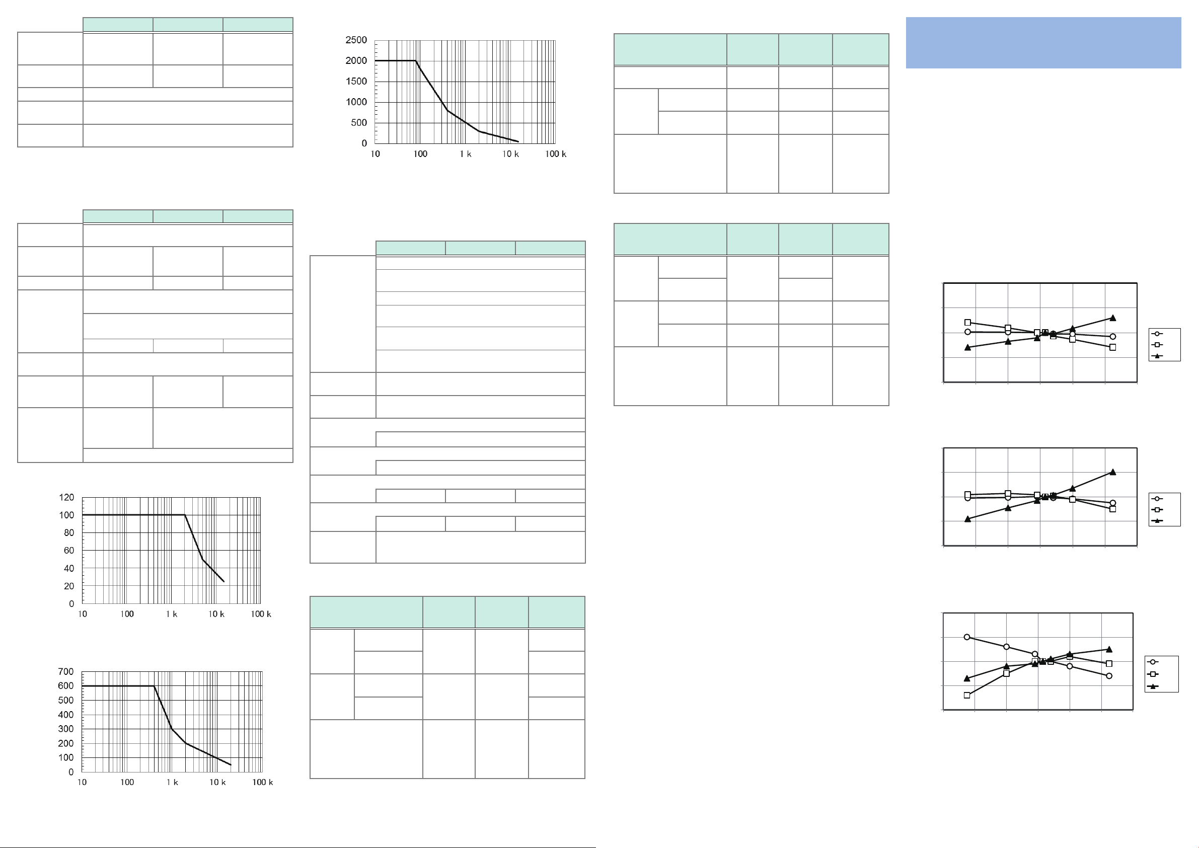
CT7631 Frequency derating
Hioki PL14
100 A AC/DC 600 A AC/DC 2000 A AC/DC
RMS value, continuous:
see “Frequency deratings” below.
Peak value
under the RMS value conditions described above.):
(
150 A peak 900 A peak 2840 A peak
DC to 10 kHz (−3 dB)
33 mm (
φ
or less
600 V AC/DC
(Measurement
category I
Anticipated transient overvoltage: 8000 V
1.30″)
φ
V)
33 mm (
φ
or less
1000 V AC/DC
(Measurement category III)
600 V AC/DC
(Measurement category IV)
1.30″)
φ
55 mm (
φ
or less
g
2.17″)
φ
CT7642 Frequency derating
Measurement current [A]
Frequency [Hz]
(2) Accuracy specications
f.s.: The rated measurement current.
rdg.: The value currently being measured and indicated on the measuring
instrument.
CT7631 CT7636 CT7642
Guaranteed accuracy period: 3 years
Guaranteed accuracy period
after adjustment made by Hioki:
Conditions of
guaranteed
accuracy
Measurement
accuracy
Temperature
coefcient
Effect of radiated radio-frequency electromagnetic eld
Effect of conducted radio-frequency electromagnetic eld
Effect of conductor position (deviation from center)
Effect of external magnetic eld (400 A/m, DC)
Maximum cord
extension
length
Opening and closing of the jaw: 30000 times or less
Accuracy guarantee for
temperature and humidity:
After performing zero-adjustment with the instrument to
which the device is connected
Accuracy of AC measurement guaranteed for sine wave
inputs
See separate table.
In the operating temperature range, add 0.1 × specied
accuracy/°C (at temperatures other than 23°C±5°C).
15% f.s. at 10 V/m
10% f.s.
at 3 V
Within ±1.5% Within ±2.0% Within ±1.0%
Within ±1.5% f.s. Within ±0.5% f.s. Within ±0.2% f.s.
100 m (Depends on the instrument to which the device is
to be connected.)
3 years
23°C±5°C (73°F±9°F),
80% RH or less
CT7636 Measurement accuracy
≤
f ≤ 66
Frequency DC
≤
±2.0% rdg.
±0.5% f.s.
±2.0% rdg.
±0.7% f.s.
±4.0% rdg.
±0.7% f.s.
Amplitude (A)
≤
Peak
(A peak)
Phase – ±1.8 deg.
|I peak|
600 < |I peak|
900
600
45
(Hz)
±2.0% rdg.
±0.5% f.s.
±2.0% rdg.
±0.7% f.s.
±4.0% rdg.
±0.7% f.s.
DC < f <
±3.0% rdg.
±0.5% f.s.
±3.0% rdg.
±0.7% f.s.
±5.0% rdg.
±0.7% f.s.
DC < f < 45
(Hz):
66 < f
(Hz):
45,
66 < f ≤ 1 k
(Hz)
±1.8 deg.
≤
1 k
Not dened.
CT7642 Measurement accuracy
≤
f ≤ 66
Frequency DC
≤
I
Amplitude
(A)
Peak
(A peak)
Phase – ±2.3 deg.
1800
1800 < I
|I peak|
2300 < |I peak|
2840
≤
≤
2000
2300
±1.5% rdg.
±0.5% f.s.
±1.5% rdg.
±1.0% f.s.
≤
±6.0% rdg.
±1.5% f.s.
45
(Hz)
±1.5% rdg.
±0.5% f.s.
±2.0% rdg.
±0.5% f.s.
±1.5% rdg.
±1.0% f.s.
±6.0% rdg.
±1.5% f.s.
DC < f <
±2.5% rdg.
±1.0% f.s.
±2.5% rdg.
±1.0% f.s.
±7.0% rdg.
±1.5% f.s.
DC < f < 45
(Hz):
66 < f
(Hz):
45,
66 < f ≤ 1 k
(Hz)
±2.3 deg.
≤
1 k
Not dened.
“Peak input” is only available in conjunction with the CM7290
Display Unit. For more information about the combination
accuracy with the instrument, see the instrument’s instruction
manual.
Amplitude accuracy design value is DC < f < 5 Hz. Phase
accuracy design value is DC < f < 10 Hz.
Zero-point Temperature
Characteristics
Hall elements are subject to individual variation, and it is
not possible to specify the magnitude or tendency of that
variation. When using the sensor in an operating environment
characterized by large temperature variations, it is
recommended to observe variation in the zero-point under noinput conditions. Zero-point variation affects DC offset by not
AC mode operation. Reference examples are provided below
to illustrate zero-point variation (23°C reference) relative
to temperature variations for each sensor. (There is also a
signicant level of variation in characteristics among individual
products.) The operating temperature range is −25°C to 65°C
(−13°F to 149°F).
(See below for example characteristics.)
CT7631
1.0
0.0
電流(A)
Current [A]
-1.0
-2.0
CT7636
1.0
0.0
電流(A)
Current [A]
-1.0
-2.0
-40 -20 0 20 40 60 80
-40 -20 0 20 40 60 80
Temperature [°C]
温度(℃)
Temperature [°C]
温度(℃)
No.1
No.2
No.3
No.1
No.2
No.3
Measurement current [A]
CT7636 Frequency derating
Measurement current [A]
CT7631 Measurement accuracy
CT7642
1.0
0.0
電流(A)
Current [A]
-1.0
-2.0
-40 -20 0 20 40 60 80
温度(℃)
Temperature [°C]
Frequency [Hz]
Frequency [Hz]
≤
f ≤ 66
Frequency DC
≤
I
Amplitude
(A)
Peak
(A peak)
Phase – ±1.8 deg.
80
≤
80 < I
100
≤
|I peak|
110 < |I peak|
150
110
≤
±1.0% rdg.
±0.5% f.s.
±1.0% rdg.
±2% f.s.
45
(Hz)
±1.0% rdg.
±0.5% f.s.
±1.0% rdg.
±2% f.s.
DC < f <
66 < f ≤ 500
(Hz)
±2.0% rdg.
±0.5% f.s.
±2.5% rdg.
±0.5% f.s.
±2.0% rdg.
±2% f.s.
±2.5% rdg.
±2% f.s.
DC < f < 45
(Hz):
±1.8 deg.
≤
66 < f
500
(Hz):
Not dened.
45,
5 6 7 8
No.1
No.2
No.3
 Loading...