

CT6876A
(Current direction indicator)
OK NO
HIOKI CT6876C961-00
CT6876A-1
AC/DC CURRENT SENSOR
Instruction Manual
Dec. 2021 Edition 1
CT6876C961-00 21-12H
www.hioki.com/
EN
DANGER
• If the cable melts, metal parts could be exposed,
posing a hazard. Keep the cable away from
sources of heat.
• Connect the device to the secondary side of a
distribution panel. If a short-circuit occurs on
the secondary side of the distribution panel, the
panel will interrupt the short-circuit current. Do
not connect the device to the primary side of the
distribution panel because an unrestricted current
ow can damage the device and facilities if a
short-circuit occurs.
Do not use the device to measure bare conductors
to which a voltage that exceeds the maximum rated
line-to-ground voltage is being applied. Doing so
could damage the device and cause bodily injury.
If the voltage exceeds the maximum rated lineto-ground voltage, measure it using an insulated
wire with the appropriate level of insulation for the
voltage in question.
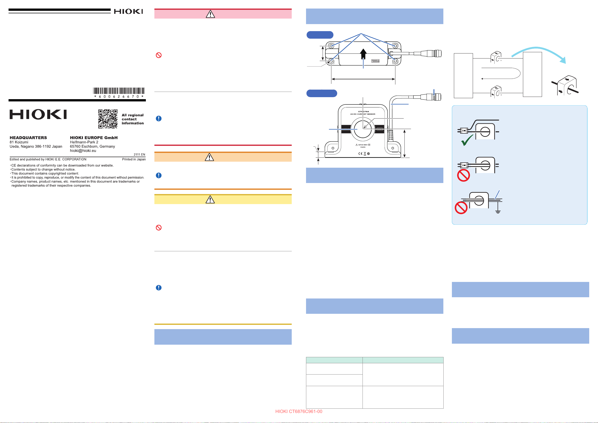
Name of Each Part
Mounting holes
Top view
32
4−φ5.2
Current direction indicator
135
Front view
Through
window
12.5
Output connector
Cable
φ36
60
Wiring
Make sure the direction of the arrow on the case matches the
direction of the current ow, as shown in the gure below. If they
are oriented incorrectly, the output signal from the sensor will be
reversed. When using the device in combination with a power meter,
conform to the power meter’s wiring method.
High
Arrow on case
LoadSource
I
Low
IMPORTANT
Pass only one conductor through the
device.
Warranty
Malfunctions occurring under conditions of normal use
in conformity with the Instruction Manual and Product
Precautionary Markings will be repaired free of charge. This
warranty is valid for a period of three (3) years from the date
of purchase. Please contact the distributor from which you
purchased the product for further information on warranty
provisions.
Introduction
Thank you for choosing the Hioki CT6876A/CT6876A-1 AC/
DC Current Sensor. To ensure your ability to get the most out
of this device over the long term, please read this manual
carefully and keep it available for future reference.
Carefully read the separate document entitled “Operating
Precautions” before use.
Intended audience
This manual has been written for use by individuals who
use the product or provide information about how to use the
product. In explaining how to use the product, it assumes
electrical knowledge (equivalent of the knowledge possessed
by a graduate of an electrical program at a technical high
school).
Troubleshooting
•
If the device seems to be malfunctioning, contact your
authorized Hioki distributor or reseller.
•
Store the device packaging material after opening the
device. When shipping the device, use the box and
packaging materials in which it was originally shipped.
WARNING
Do not place the cable in contact with the
measured line. Any contact can cause the device
to malfunction and lead to a short-circuit or electric
shock.
CAUTION
• To prevent cable damage, do not step on cables or
pinch them between other objects. Do not bend or pull
on cables at their base.
• Do not place the device on an unstable table or
uneven surface. Doing so could cause the device to
fall or turn over, causing bodily injury or damage to the
device.
• The cable is hardened in freezing temperatures. Do
not bend or pull it to avoid tearing its shield or causing
a break.
• When the power to lines to be measured is turned on
or o, a current owing through the lines can exceed
considerably the maximum allowable current of the
device. This could result in damage to the device.
Make sure that there is not any over-current.
• Do not apply current to the lines to be measured while
the device turned o. This could result in damage to
the device.
Overview
This pull-through current sensor has excellent frequency
characteristics (amplitude, phase) and temperature
characteristics (sensitivity, oset), which enables
power measurement as well as current measurement.
Use with Other Hioki Products
This device is used in connection with a dedicated instrument
(Hioki product). Refer to combined accuracy and conditions
specied in the specications for details.
high-precision
(Unit: mm)
Options
The options listed below are available for the device. To order an
option, please contact your authorized Hioki distributor or reseller.
Options are subject to change. Check Hioki’s website for the latest
information.
CT9901 Conversion Cable
Connecting the CT9901 enables the device to connect to an
instrument that does not support direct connection with the device (No
accuracy is aected).
CT9902 Extension Cable
• Connecting a CT9902 enables the device cable to be extended by
5 m (max. 10 m).
• Up to two of the Extension Cable available (If three or more
extension cables are connected to the device, its performance is
not guaranteed).
• Add the following to the sensor accuracy for each cable used:
Amplitude accuracy: ±0.1% of reading (DC ≤ f* ≤ 1 kHz)
±(0.1 + 0.01 × f*)% of reading (1 kHz < f*)
Phase accuracy: ±(0.03 × f*)° (1 kHz < f*)
*: frequency
Measurement Procedure
For correct measurement, connect the device to a measuring
instrument with an input impedance of 1 M
Inspection Before Use
Check the device for any damage that may have occurred during
storage or shipping before use. If you nd any damage to the device,
please contact your authorized Hioki distributor or reseller for repair.
Check Items Remedy
Is the device cracked or
damaged?
Is the cable insulation
torn?
Is the cable broken at the
base (of the connector or
the sensor)?
If there is any damage, electric
shock may result. Discontinue use
and contact your authorized Hioki
distributor or reseller.
Broken connections will make proper
measurement impossible.
Discontinue use and contact your
authorized Hioki distributor or reseller.
±10%.
Ω
Passing two or more of conductors
in a bundle prevents the device from
measuring any current regardless of
whether the measurement target is a
single-phase or three-phase circuit.
Shield
Ground-shielded conductors cannot
be accurately measured.
• Arrange the conductor as close to the center of the through window
as possible. For a current to be measured of frequency 1 kHz or
more, the conductor position could cause increase in measured
value error or distortion of output-signal waveforms.
• If a conductor not being measured carries a current of frequency
1 kHz or more, keep such conductor at least 100 mm away
from the device. Failure to observe this could cause increase in
measured value error or distortion of output signal waveforms.
• Use the device with its surface temperature of 105°C or less.
Phase Compensation Values
Enter the following compensation values (representative values)
when performing phase compensation on the PW6001 or PW3390.
CT6876A: 200 kHz,
CT6876A-1: 200 kHz,
−
12.96°
−
14.34°
Specications
Accuracy
Reading (displayed value):
Indicates the value displayed by the instrument. Limit values for
reading errors are expressed as a percentage of the reading (“% of
reading” or “% rdg”).
Range:
Indicates the instrument’s range. Limit values for range errors are
expressed as a percentage of the range (“% of range” or “% rng”).
Full scale (rated current):
Indicates the rated current. Limit values for full-scale errors are
expressed as a percentage of full scale (“% of full scale” or “% f.s.”).
Operating
Frequency [Hz]
TA: Ambient temperature
4
2
-8
-6
-4
-2
0
2
4
-10
-8
-6
-4
-2
0
2
10 100 1 k 10 k 100 k 1 M
Gain
Phase
Phase (compensated)
-8
-6
-4
-2
0
2
4
-10
-8
-6
-4
-2
0
2
10 100 1 k 10 k 100 k 1 M
Gain
Phase
Phase (compensated)
100
120
140
160
180
200
10 100 1 k 10 k 100 k 1 M
30
HIOKI CT6876C961-00
environment
Operating
temperature and
Indoor use, pollution degree 2,
altitude up to 2000 m (6562 ft.)
−40°C to 85°C (−40°F to 185°F)
80% RH or less (non-condensing)
humidity range
Storage temperature
and humidity range
−40°C to 85°C (−40°F to 185°F)
80% RH or less (non-condensing)
Standards Safety: EN 61010
EMC: EN 61326
Withstand voltage 7.4 kV AC (sensed current: 1 mA) 50 Hz/60 Hz for
1 minute, between through window and cable
output terminal
Power supply
Supplied from PW8001, PW6001, PW3390, CT9555,
CT9556, CT9557, U8977 or external DC power supply
Rated supply voltage: ±11.5 V to ±15 V (Tracking)
Maximum rated current: ±450 mA (1000 A/55 Hz
measurement, ±12 V
power supply)
Maximum rated power
7.5 VA (1000 A/55 Hz measurement, ±12 V power supply)
Interface Dedicated interface (ME15W)
Dimensions Approx. 160W × 112H × 50D mm
(6.30″W × 4.41″H × 1.97″D)
(excluding protrusions and the cable)
Output cable length CT6876A: Approx. 3 m
CT6876A-1: Approx.10 m
Mounting hole
diameter
5.2 mm (M5 screw, recommended tightening
φ
torque: 1.5 Nm to 2.0 Nm)
Weight CT6876A: Approx. 970 g (34.2 oz.)
CT6876A-1: Approx. 1300 g (45.9 oz.)
Product warranty
duration
Accessories Mark bands ×6
3 years
Instruction Manual
Options CT9901 Conversion Cable
Memory function Sensor information can be read for products with
Rated current 1000 A AC/DC
Measurable
conductor diameter
Maximum input
current
Operating Precautions (0990A907)
CT9902 Extension Cable
memory function support.
Applicable product: PW8001
36 mm or less
φ
Not exceeding derating curve shown in Figure 1
However, a current of up to ±1800 A peak (design
value) is allowable for up to 20 ms at 40°C or less.
Output voltage 2 mV/A
Maximum rated
line-to-ground voltage
Output resistance 50
Accuracy guarantee
conditions
1000 V (Measurement category III)
Anticipated transient overvoltage: 8000 V
±10
Ω
Ω
Accuracy guarantee duration: 1 year
Accuracy guarantee duration after adjustment made by
Hioki: 1 year
Accuracy guarantee temperature and humidity range:
0°C to 40°C (32°F to 104°F), 80% RH or less
Measurement accuracy
Frequency
No warm-up required, sine wave inputted, connected with
measuring instrument with input resistance 1 MΩ ±10%,
line-to-ground voltage: 0 V, no external magnetic eld,
conductor arranged at center of window
Amplitude
±(% of reading + % of full scale)
DC 0.04% + 0.008%
DC < f < 16 Hz 0.1% + 0.02% ±0.1°
16 Hz ≤ f < 45 Hz 0.05% + 0.01% ±0.1°
45 Hz ≤ f ≤ 66 Hz 0.04% + 0.008% ±0.08°
66 Hz < f ≤ 100 Hz 0.05% + 0.01% ±0.1°
100 Hz < f ≤ 500 Hz 0.1% + 0.02% ±0.2°
500 Hz < f ≤ 1 kHz 0.2% + 0.02% ±0.4°
1 kHz < f ≤ 5 kHz 0.5% + 0.02% ±0.5°
5 kHz < f ≤ 10 kHz 0.5% + 0.02% ± (0.1 × f)°
10 kHz < f ≤ 50 kHz 2% + 0.05% ± (0.1 × f)°
50 kHz < f ≤ 100 kHz 3% + 0.05% ± (0.1 × f)°
100 kHz < f ≤ 1 MHz
Frequency range 1.5 MHz
0.03 × f)%
(
(
+
0.05%
±3 dB Typical
)
Phase
-
± (0.1 × f)°
-
• The variable f in accuracy equations is expressed in kHz.
• Accuracy of amplitude and phase is specied with 110% of full scale input
or less and not exceeding derating curve in Figure 1.
However, design values are given for DC < f < 10 Hz.
• Add ±0.01% of reading to amplitude accuracy when input is 100% of full
scale to 110% of full scale.
• For the CT6876A-01, add the following values to accuracy in the range of
1 kHz < f ≤ 1 MHz.
Amplitude accuracy: ±(0.005 × f [kHz])% of reading
Frequency bandwidth: 1.2 MHz (±3 dB Typical)
Phase accuracy: ±(0.015 × f [kHz])°
Linearity error *
Oset voltage *
Amplitude error *
±5 ppm Typical (23
2
±5 ppm Typical (23
3
DC: ±10 ppm Typical*
°C)
°C, no input)
2
1 *2
10 Hz to 100 Hz: ±0.005% Typical
100 Hz to 1 kHz: ±0.03% Typical
1 kHz to 10 kHz: ±0.2% Typical
10 kHz to 100 kHz: ±1% Typical
100 kHz to 300 kHz: ±3% Typical
300 kHz to 1 MHz: ±15% Typical
*1: Measuring the output voltage while cycling the input current (DC) from
−
+1000 A → 0 A→
1000 A → 0 A → +1000 A at an interval of 200 A.
Dened as the dierence between the regression line calculated from
the above measurements and the measurement points.
*2: Dened as a percentage of the rated current.
*3: DC error is dened as (linearity error + oset voltage).
AC error is dened as deviation from the 55 Hz measurement point.
Output noise 300 µV rms or less (≤ 1 MHz)
Eects of
temperature
Within the range of −40°C to 0°C or 40°C to 85°C
Amplitude sensitivity: ±20 ppm of reading/°C
Oset voltage: ±1 ppm of full scale/°C
Eects of
magnetization
Common mode
rejection ratio
(CMRR)
Eects of conductor
position
20 mA or less
(input equivalent, after 1000 A DC is inputted)
140 dB or more (50 Hz/60 Hz)
120 dB or more (100 kHz)
(Eect on output voltage / common-mode voltage)
DC, 50 Hz/60 Hz: ±0.01% of reading or less
(input current: 100 A)
10 kHz: ±0.5% of reading or less (input current: 10 A)
100 kHz: ±3% of reading or less (input current: 10 A)
When wire of outer diameter 10 mm is used
Eects of external
magnetic eld
Eects of radiated
40 mA or less (input equivalent, under a magnetic
eld of 400 A/m DC or 400 A/m with 60 Hz)
0.5% of full scale or less at 10 V/m
radio-frequency
electromagnetic eld
Eects of conducted
0.2% of full scale or less at 10 V
radio-frequency
electromagnetic eld
Connectable products
1. PW8001 Power Analyzer
-1. U7001 Combined accuracy
Frequency
DC 0.06% + 0.058% 0.06% + 0.058%
45 Hz ≤ f ≤ 66 Hz
Bands other than
DC and
45 Hz ≤ f ≤ 66 Hz
• For other measurement parameters, U7001 accuracy + sensor
accuracy (consider sensor rating for full scale error).
• For the 20 A range or the 40 A range, add ±0.15% of range.
• Add accuracy according to each condition in specications of the
power analyzer and sensor.
• Dened after zero adjustment has been performed.
-2. U7005 Combined accuracy
Frequency
DC 0.06% + 0.038% 0.06% + 0.038%
45 Hz ≤ f ≤ 66 Hz
Bands other than
DC and
45 Hz ≤ f ≤ 66 Hz
Current Power
±(% of reading + % of range)
0.06% + 0.058% 0.06% + 0.058%
U7001 accuracy + sensor accuracy
(Consider sensor rating for full scale error.)
Current Power
±(% of reading + % of range)
0.05% + 0.028% 0.05% + 0.028%
U7005 accuracy + sensor accuracy
(Consider sensor rating for full scale error.)
Phase
U7001
accuracy
+
sensor
accuracy
Phase
U7005
accuracy
+
sensor
accuracy
• For other measurement parameters, U7005 accuracy + sensor
accuracy (consider sensor rating for full scale error).
• For the 20 A range or the 40 A range, add ±0.15% of range.
• Add accuracy according to each condition in specications of the
power analyzer and sensor.
• Dened after zero adjustment has been performed.
2. PW6001 Power Analyzer
Combined accuracy
Frequency
DC 0.06% + 0.038% 0.06% + 0.058%
45 Hz ≤ f ≤ 66 Hz
Bands other than
DC and
45 Hz ≤ f ≤ 66 Hz
Current Power
±(% of reading + % of range)
0.06% + 0.028% 0.06% + 0.038%
PW6001 accuracy + sensor accuracy
(Consider sensor rating for full scale error.)
Phase
PW6001
accuracy
+
sensor
accuracy
• For other measurement parameters, PW6001 accuracy + sensor
accuracy (consider sensor rating for full scale error).
• For the 20 A range or the 40 A range, add ±0.15% of range.
• Add accuracy according to each condition in specications of the
power analyzer and sensor.
• Dened after zero adjustment has been performed.
3. PW3390 Power Analyzer
Combined accuracy
Frequency
DC 0.09% + 0.078% 0.09% + 0.078%
45 Hz ≤ f ≤ 66 Hz
Bands other than
DC and
45 Hz ≤ f ≤ 66 Hz
• For other measurement parameters, PW3390 accuracy + sensor
accuracy (consider sensor rating for full scale error).
• For the 20 A range or the 40 A range, add ±0.15% of range.
• Add accuracy according to each condition in specications of the
power analyzer and sensor.
• Dened after zero adjustment has been performed.
4. CT9555, CT9556, CT9557 Sensor Unit
Combined accuracy
• Sensor accuracy is applicable (with output coaxial cable of length
1.6 m or less).
• Add sensor unit accuracy when RMS output or total output is used.
• Add accuracy according to each condition in specications of the
products to be connected and sensor.
5. U8977 3CH Current Unit
Combined accuracy
• (U8977 accuracy) + (sensor accuracy)
• Add accuracy according to each condition in specications of
Memory HiCorder to be connected and sensor.
• Dened after zero adjustment has been performed.
6. Other connectable products
Connecting CT9901 Conversion Cable enables the device to be
used in combination with the following products:
Combined
product
9555-10
Sensor Unit
3390, 3390-10
Power Analyzer
9602
AC/DC Clamp
Input Unit
3334-10
AC/DC Power
HiTester
Current Power
±(% of reading + % of range)
Phase
PW3390
0.08% + 0.058% 0.08% + 0.058%
PW3390 accuracy+ sensor accuracy
(Consider sensor rating for full scale error.)
accuracy
+
sensor
accuracy
Combined accuracy and conditions
(Combined accuracy) =
Sensor accuracy
With output coaxial cable of length 1.6 m or less
Recognized as [AC/DC 500 A]. Set CT ratio to [2].
(Combined accuracy) = (3390 (-10) accuracy) + (sensor
accuracy), (power factor: 1)
Dened after zero adjustment has been performed.
When installed in 3193-10, recognized as [AC/DC 500 A].
Set CT ratio to [2].
(Combined accuracy) = (9602 accuracy) + (sensor
accuracy) + (±0.1% of reading);
(power factor: 1)
Dened after zero adjustment has been performed.
Recognized as [AC/DC 500 A]. Set CT ratio to [50].
(Combined accuracy) = (3334-10 accuracy) + (sensor
accuracy); (power factor: 1)
Dened after zero adjustment has been performed.
Combined
product
8971
Current Unit
The 9318 Conversion Cable (accessory of 8971) is required.
Recognized as [AC/DC 500 A] by the instrument equipped
Combined accuracy and conditions
with auto-recognition. Set SC ratio to [2].
(Combined accuracy) = (8971 accuracy) + (sensor accuracy)
Dened after zero adjustment has been performed.
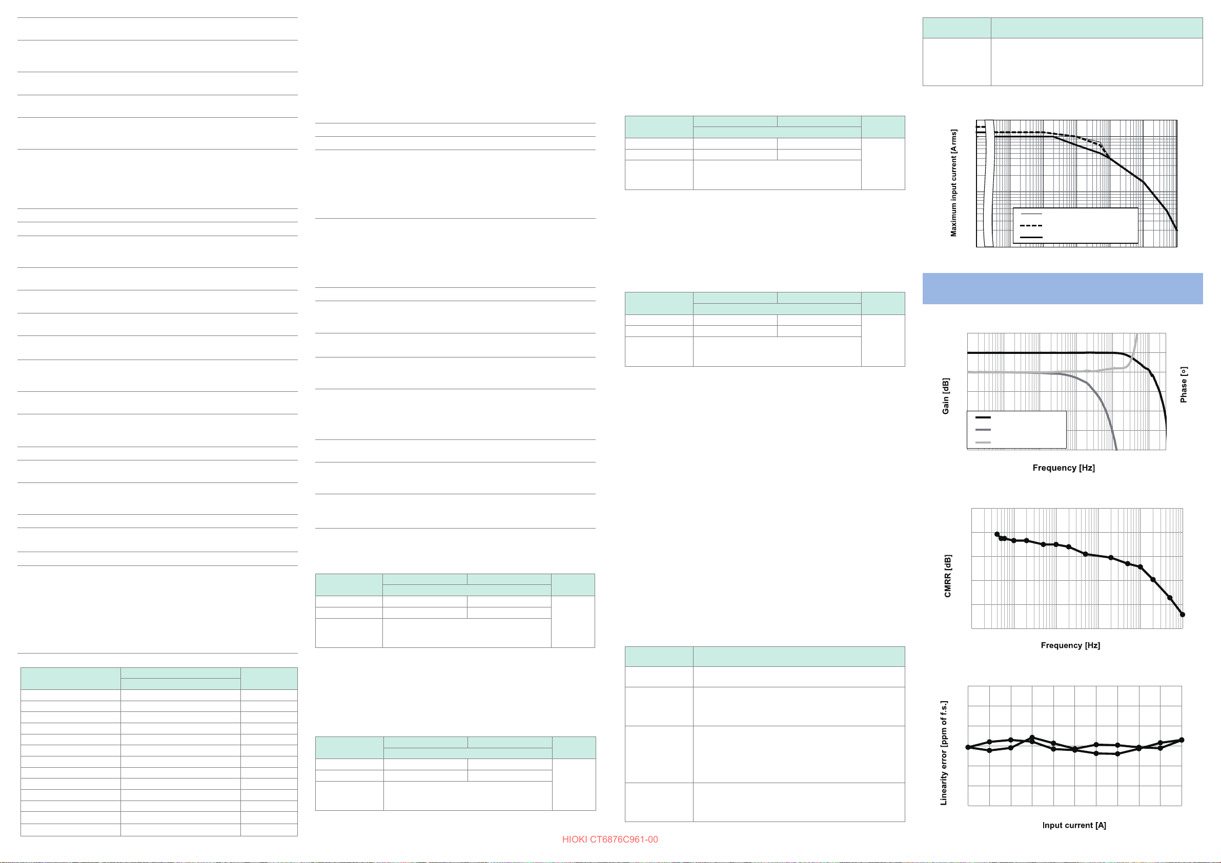
Figure 1. Frequency Derating Curve
2 k
1 k
100
-40℃ ≤ TA ≤ 40℃(1 minute)
-40℃ ≤ TA≤ 40℃ (1 minute)
-40℃ ≤ TA ≤ 60℃(Continuous)
-40℃ ≤ TA≤ 60℃ (Continuous)
-40℃ ≤ TA ≤ 85℃(Continuous)
10
1 10 100 1 k 10 k 100 k 1 M
DC
-40℃ ≤ TA≤ 85℃ (Continuous)
Characteristics
Frequency characteristics (Typical)
0
-2
-4
-6
-8
-10
CMRR (Typical)
200
180
160
140
120
100
Linearity error (Typical)
20
10
0
-10
-20
-30
-1000 -800 -600 -400 -200 0 200 400 600 800 1000
Gain
Phase
Phase (compensated)
10 100 1 k 10 k 100 k 1 M
10 100 1 k 10 k 100 k 1 M
2
0
-2
-4
-6
-8
 Loading...