

Page 1
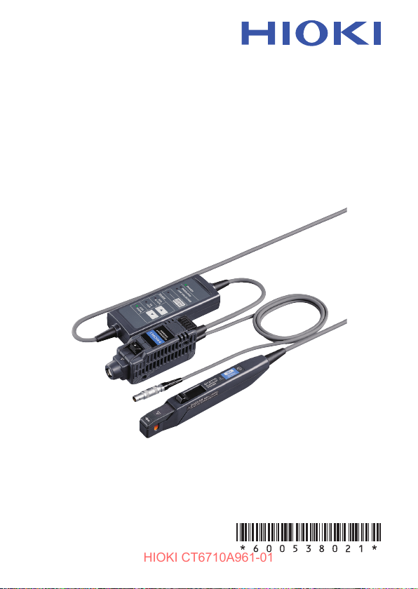
CT6710
HIOKI CT6710A961-01
CT6711
CURRENT PROBE
Instruction Manual
Aug. 2020 Revised edition 1
CT6710A961-01 20-08H
EN
Page 2

HIOKI CT6710A961-01
Page 3
Measurement Procedure
HIOKI CT6710A961-01
Be sure to familiarize yourself with the “Usage Notes”
section (p. 8), each instruction of use, and safety notes
presented at the beginning of each instruction of use.
Inspecting the Device Before Use
Preparing for Measurement
• Provide power to the device.
• Connect the termination unit to your waveform
measuring instrument.
• Execute demagnetization and automatic zero-
adjustment.
Measuring Currents
• Clamp the sensor around a conductor to be
measured.
• Measure a current.
Finishing Measurement
CT6710A961-01
(p. 26)
(p. 28)
(p. 41)
(p. 65)
Page 4
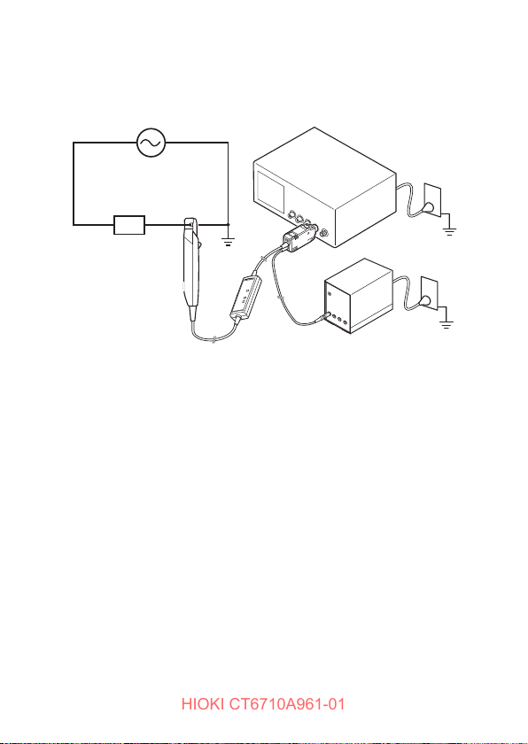
Connection Example
HIOKI CT6710A961-01
Waveform measuring instrument
H
Power source
Load
See “Example of connection to the circuit to be measured”
(p. 49).
L
Model 3269 Power Supply
Page 5

Contents
HIOKI CT6710A961-01
Introduction .....................................................................................1
Notations ......................................................................................... 2
Checking Package Contents ......................................................... 5
Safety Notes .................................................................................... 7
Usage Notes .................................................................................... 8
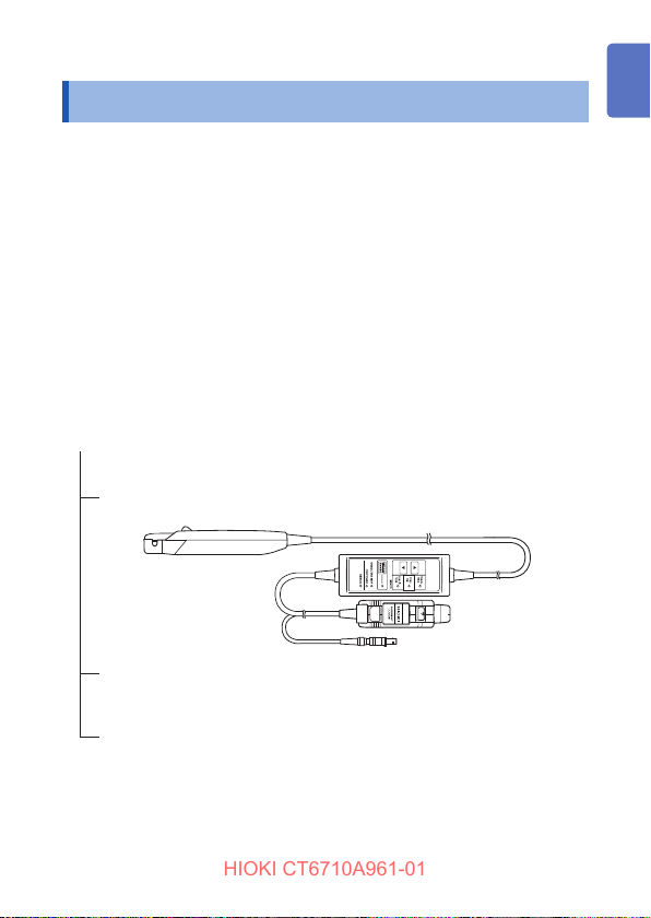
1 Overview 13
1.1 Product Overview ...................................................13
1.2 Product Features ....................................................14
1.3 Name and Function of Each Part ..........................16
Termination unit .................................................................... 16
Junction box (keys, LEDs) .................................................... 18
Sensor .................................................................................. 20
1.4 Specications of Lighting Up / Blinking LEDs ..... 22
2 Current Measurement 25
2.1 Inspecting the Device Before Use ......................... 26
2.2 Preparing for Measurement ................................... 28
Providing power to the CT6710/CT6711 ............................... 29
Executing demagnetization and automatic
zero-adjustment .................................................................... 33
2.3 Measuring Currents ................................................ 41
How to measure a current .................................................... 50
To measure a low current ..................................................... 58
To measure a current accurately .......................................... 60
When the device has entered protection mode .................... 62
2.4 Finishing Measurement .......................................... 65
1
2
3
4
Index
i
Page 6

Contents
HIOKI CT6710A961-01
3 Specications 69
3.1 General Specications ........................................... 69
3.2 Specications of Input, Output, and
Measurement ........................................................... 71
Basic specications .............................................................. 71
Specications of accuracy .................................................... 73
3.3 Specications of Functionality .............................. 75
3.4 Typical Characteristics ...........................................77
Frequency characteristics ..................................................... 77
Frequency derating curve ..................................................... 78
Input impedance ................................................................... 80
Consumption current ............................................................ 81
Inuence of common-mode voltage ...................................... 82
4 Maintenance and Service 83
4.1 Troubleshooting ......................................................84
Before sending back your device for repair .......................... 85
4.2 Errors ....................................................................... 88
Types of errors ...................................................................... 89
4.3 Cleaning ................................................................... 96
4.4 Disposal ................................................................... 97
Index 99
Warranty
ii
Page 7

Introduction
HIOKI CT6710A961-01
Introduction
Thank you for choosing the Hioki CT6710, CT6710 Current
Probe. To ensure your ability to get the most out of this
device over the long term, please read this manual carefully
and keep it available for future reference.
Each model oers a dierent frequency band listed below:
Model CT6710: DC to 50 MHz
Model CT6711: DC to 120 MHz
The following manuals are provided along with these
models. Refer to manuals relevant to your purpose.
• Current Sensor Operating Precautions
Information on the device for safe operation
• Instruction Manual (this document)
Basic instructions and specications of the device
Please review the separate “Current Sensor Operating
Precautions” before using the device.
Target audience
This manual has been written for use by individuals who use
the product in question or who teach others to do so.
It is assumed that the reader possesses basic electrical
knowledge (equivalent to that of someone who graduated
from the electrical program at a technical high school).
1
Page 8

Notations
HIOKI CT6710A961-01
Notations
Safety notations
This manual classies seriousness of risks and hazard
levels as described below.
Indicates an imminently hazardous situation
DANGER
WARNING
CAUTION
that, if not avoided, will result in death or
serious injury.
Indicates a potentially hazardous situation
that, if not avoided, could result in death or
serious injury.
Indicates a potentially hazardous situation
that, if not avoided, could result in minor or
moderate injury.
NOTICE
IMPORTANT
NOTE
Indicates a high-voltage hazard.
Failure to verify safety or improper handling of the device
could lead to electric shock, burn injury, or death.
2
Indicates potential risks of damage to the
supported product (or to other property).
Indicates information or content that is
particularly important from the standpoint of
operating or maintaining the device.
Indicates useful advice concerning device
performance and operation.
Page 9
Indicates an action that must not be performed.
HIOKI CT6710A961-01
Indicates an action that must be performed.
Symbols shown on the device
Indicates the presence of a potential hazard. For more
information about locations where this symbol appears
on device components, see the “Usage Notes” section
(p. 8), warning messages listed at the beginning of
operating instructions, and the accompanying document
entitled “Current Sensor Operating Precautions.”
Indicates that the device can only be used at a location
on an insulated wire with sucient insulation for the
circuit voltage.
Symbols for various standards
Indicates the Waste Electrical and Electronic Equipment
Directive (WEEE Directive) in EU member states.
Indicates that the product complies with standards
imposed by EU directives.
Notations
3
Page 10

Notations
HIOKI CT6710A961-01
Others
*
Indicates additional information is described below.
Bold
Indicates the names of the control keys.
Accuracy
Hioki denes tolerances for measured values in terms of
percentage of reading, as indicated below.
Reading (Displayed value)
Indicates the value the measuring instrument
rdg.
displays. Tolerances for reading errors are
expressed in percent of reading (% of reading,
% rdg).
4
Page 11
Checking Package Contents
HIOKI CT6710A961-01
Checking Package Contents
When you receive the device, inspect it to ensure that
no damage occurred during shipment. Pay particular
attention to keys and connectors. If you nd any damage
or discover that the device does not perform as indicated
in its specications, please contact your authorized Hioki
distributor or reseller.
Check that the package contents are correct.
The carrying case contains the current probe, Instruction
Manual, and Current Sensor Operating Precautions.
Carrying case
(Accessory)
Model CT6710/CT6711 Current Probe
Instruction Manual
(Accessory)
Current Sensor Operating Precautions
(0990A901)
(Accessory)
5
Page 12

Checking Package Contents
HIOKI CT6710A961-01
Option
The option below is available for the device. To order an
option, please contact your authorized Hioki distributor or
reseller.
Options are subject to change. Check Hioki’s website for the
latest information.
Model 3269 Power Supply
The 3269 Power Supply can provide the power to up to
two probes of the CT6710/CT6711.
(The 3272 Power Supply cannot be used as a power
supplying unit for the CT6710/CT6711.)
Precautions for transportation
• Store packaging materials for future use. You will need the
packaging materials when shipping the device.
• Transport the device in its carrying case.
6
Page 13
Safety Notes
HIOKI CT6710A961-01
Safety Notes
The device has been designed in accordance with the IEC
61010 safety standard, and its safety has been veried by
means of testing prior to shipment. However, failure to follow
the information in this manual could render safety-related
functionality provided by the device ineective.
Please review the safety information below before using the
device.
DANGER
Read this manual carefully and ensure you
understand its contents before using the
device.
Improper use of the device could result in serious bodily
injury or damage to the device.
WARNING
If using an electrical measuring instrument
for the rst time, seek instruction from an
individual with electrical measurement
experience rst.
Failure to do so may lead to electric shock, overheating,
re, arcing due to a short-circuit, or other hazards.
7
Page 14
Usage Notes
HIOKI CT6710A961-01
Usage Notes
Be sure to follow the precautions listed below in order to use
the device safely and in a manner that allows it to function
eectively.
Use of the device should conform not only to its
specications, but also to the specications of all
accessories, options, and other equipment in use.
DANGER
Do not use the device for measuring bare
conductors.
Take measurements at a location on an
insulated wire with sucient insulation for the
circuit voltage.
Doing so may result in electric shock or a short-circuit.
8
Page 15
Usage Notes
HIOKI CT6710A961-01
DANGER
Do not remove any covers of the sensor,
junction box, and termination unit.
The internal components of the device carry high
voltages and may become very hot during operation.
Touching them could cause electric shock or burns.
Do not connect the device to the primary side
of a distribution panel.
If a short-circuit occurs on the primary side, an
unrestricted current ow can damage the device
and facilities, resulting in serious bodily injury. Even
if a short-circuit occurs on the secondary side of the
distribution panel, the panel will interrupt the short-
circuit current.
Do not use the device in powerful magnetic
elds.
Doing so could cause the sensor to become abnormally
hot, resulting in bodily injury, damage to the device, or
re.
Follow all operating precautions for a
waveform measuring instrument or any other
measuring instruments to which this device is
connected.
Failure to observe this could cause serious bodily injury
or damage to these instruments.
9
Page 16
Usage Notes
HIOKI CT6710A961-01
Do not use the device to measure circuits that
Do not install the instrument in locations such
WARNING
exceed the ratings or specications of the
device.
Doing so could cause damage to the device or
overheating, resulting in bodily injury.
as the following:
• In locations where it would be subject to direct
sunlight
• In locations where it would be subject to high
temperatures
• In locations where it would be exposed to corrosive
or explosive gases
• In locations where it would be exposed to water, oil,
chemicals, or solvents
• In locations where it would be exposed to high
humidity or condensation
• In locations where it would be exposed to powerful
electromagnetic radiation
• Close to objects carrying an electric charge
• In locations with an excessive amount of dust
• Close to inductive heating devices (high-frequency
inductive heating devices, IH cooktops, etc.)
• In locations characterized by a large amount of
mechanical vibration
• Close to HF power supply units
Doing so could cause damage to the device or cause it
to malfucntion, resulting in bodily injury.
10
Page 17
Usage Notes
HIOKI CT6710A961-01
WARNING
Ensure that the insulation on the cords is
undamaged and that no bare conductors are
improperly exposed before using the device.
Any damage to the cords leads to electric shock.
Contact your authorized Hioki distributor or reseller for
repair.
CAUTION
Do not place the device on an unstable stand
or angled surface.
Doing so could cause the device to fall or overturn,
resulting in bodily injury or damage to the device.
Properly connect the device to a circuit to
be measured and your waveform measuring
instrument.
Improperly connecting them could cause electric shock
or damage to the circuit, device, or your instrument.
11
Page 18

Usage Notes
HIOKI CT6710A961-01
Do not store or use the device in locations
Do not apply force in the directions shown in
Do not
apply force.
Keep the upper jaw locked in place when the
NOTICE
subject to abrupt temperature changes.
Doing so could damage the sensor heads.
the gure below while the upper jaw is locked
in place.
Opening lever position
when the upper jaw is
locked in place
Doing so may damage the retracting/extending
mechanism.
device is not in use.
Leaving the upper jaw unlocked will cause dust or dirt to
settle on the facing core surfaces, resulting in damage
to the device.
12
Page 19
1
HIOKI CT6710A961-01
Overview
1.1 Product Overview
Model CT6710/CT6711 is a clamp-on current probe that
features high current-detection sensitivity and broad
frequency band. The probe uses three current ranges to
detect current waveforms from 1 mA to 50 A.
You can directly connect the termination unit to a BNC input
terminal of your waveform measuring instrument such as
an oscilloscope and recorder, and then clamp the sensor
around a conductor to be measured to observe current
waveforms easily.
Sensor (p. 20)
Junction box (p. 18)
Termination unit (p. 16)
1
13
Page 20

Product Features
HIOKI CT6710A961-01
1.2 Product Features
Clamp-on sensor heads (p. 21)
The clamp-on sensor heads allow current measurement
without the need to make physical contact with a
conductor to be measured or to disconnect it. You can
observe current waveforms while maintaining the ow of
electric current.
Sliding jaw retracting/extending mechanism
(p. 21)
This feature lets you easily retract, extend, and lock the
upper jaw in place to clamp the sensor around a conductor
to be measured.
Easy-to-connect output terminal (p. 17, p. 38)
Insert the output terminal into a BNC input terminal on
your waveform measuring instrument to connect the
termination unit.
Warning LED lights (p. 18)
The warning LEDs alert you to an overload (indicating
that an input current value exceeds the rated current of
the device) or jaw-unlocked condition (indicating that the
upper jaw has not been locked in place).
14
Page 21

Product Features
HIOKI CT6710A961-01
Three current measurement ranges (p. 53)
You can choose from the three ranges according to the
magnitude of the current to be measured. This feature lets
you observe a wide range of currents, from 1 mA to 50 A.
Broad frequency band (p. 71)
Model CT6710: DC to 50 MHz
Model CT6711: DC to 120 MHz
Demagnetizing and automatic zero-adjustment
functions (p. 33)
You can use a single key to demagnetize the magnetic
cores and correct variations in oset voltage, both of
which are required before measuring.
Protection mode (p. 62)
The device automatically enters protection mode to
prevent damaging itself when overheating.
1
15
Page 22
Name and Function of Each Part
HIOKI CT6710A961-01
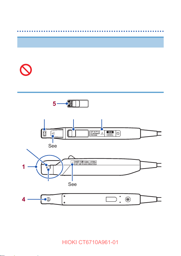
1.3 Name and Function of Each Part
Termination unit
See p. 34 and p. 35.
Top view
1 2
5
16
3
4
6
Page 23
Name and Function of Each Part
HIOKI CT6710A961-01
Output terminal
1
The device converts a captured current waveform into a
voltage waveform by multiplying a particular rate according
to a specied current range and outputs the voltage
waveform from this terminal. Connect this terminal to a BNC
input terminal of your waveform measuring instrument.
Unlock lever
2
To disconnect the output terminal, pull on the termination unit
while simultaneously pulling this lever.
Vents
3
The unit has the vents on the sides and bottom. Do not clog
them.
Serial number
4
The serial number consists of nine digits. The rst two digits
indicate the year of manufacture, while the second two
digits indicate the month of manufacture. Do not remove this
sticker as the number is important.
Power plug
5
Power is provided to the CT6710/CT6711 through this plug.
Connect this plug with the 3269 Power Supply.
Shell
6
Pull on the power plug while simultaneously pulling this shell
to disconnect the plug.
1
You can easily connect and disconnect
the termination unit with two ngers
even when multiple termination units
are connected to a waveform measuring
instrument.
17
Page 24

Name and Function of Each Part
HIOKI CT6710A961-01
Junction box (keys, LEDs)
4
5
6
7
1
8
DEMAG / AUTO ZERO key
1
Hold down
(about 1 s)
Press momentarily
(less than 0.5 s)
(Higher range) key (p. 53)
2
Switch over to a next higher current range.
(Does not switch from the 30 A range to the 0.5 A range)
(Lower range) key (p. 53)
3
Switch over to a next lower current range.
(Does not switch from the 0.5 A range to the 30 A range)
18
2
3
Top view
Performs demagnetization followed by
automatic zero-adjustment. (p. 33)
Performs automatic zero-adjustment
alone. (p. 40)
Page 25

Name and Function of Each Part
HIOKI CT6710A961-01
POWER LED (green light)
4
• Lights up when the power is on (p. 31). (Normal operation)
• Rapidly blinks when a checksum error has occurred (p. 95).
OVERLOAD LED (red light)
5
• Flashes three times when demagnetizing or automatic zeroadjustment cannot be performed (p. 91).
• Rapidly blinks when an overload state is detected (p. 90),
the device has entered protection mode (p. 62), or a
checksum error has occurred (p. 95).
JAW UNLOCKED LED (red light)
6
• Lights up when the upper jaw is unlocked.
• Flashes three times when demagnetizing or automatic zero-
adjustment cannot be performed (p. 91).
• Rapidly blinks when the device has entered protection mode
(p. 62) or a checksum error has occurred (p. 95).
DEMAG / AUTO ZERO LED (orange light)
7
• Slowly blinks when demagnetization or automatic zeroadjustment has not yet been performed (p. 33).
• Lights up when demagnetization and automatic zeroadjustment are
• Goes out when demagnetization and automatic zeroadjustment have been completed (p. 39).
• Flashes three times when demagnetization and automatic
zero-adjustment cannot be performed (p. 91).
• Rapidly blinks when the device has entered protection mode
(p. 62) or a checksum error has occurred (p. 95).
RANGE LEDs (green lights)
8
• Lights up when its current range is chosen (p. 53). (Normal
operation)
• Blinks rapidly when the device has entered protection mode
(p. 62) or a checksum error has occurred (p. 95).
in execution
(p. 39).
1
19
Page 26
Name and Function of Each Part
HIOKI CT6710A961-01
Sensor
NOTICE
Do not store or use the device in locations
subject to abrupt temperature changes.
Do not apply force or mechanical shock to the
device.
Do not subject the device to static electricity.
Doing so could damage the device.
4
2
See p. 41.
1
3
4
20
5
6
See p. 41.
When the upper jaw is unlocked
See p. 41.
Top view
Page 27

Name and Function of Each Part
HIOKI CT6710A961-01
Jaws
1
Clamp this part around a conductor to be measured by
operating the opening lever, which allows the upper jaw to
slide (retract/extend).
Sensor aperture
2
A conductor to be measured must pass through this
aperture.
Sensor heads
3
The sensor heads, located inside the jaws, detects currents.
Current direction indicator
4
Clamp the sensor around the conductor such that the
direction this arrow indicates matches the current direction of
a conductor to be measured.
JAW UNLOCKED indicator
5
If this indicator appears, the upper jaw is not locked in place.
Opening lever
6
To retract and extend the upper jaw, always operate this
lever. This lever allows you to retract and lock the upper jaw
in place.
1
21
Page 28
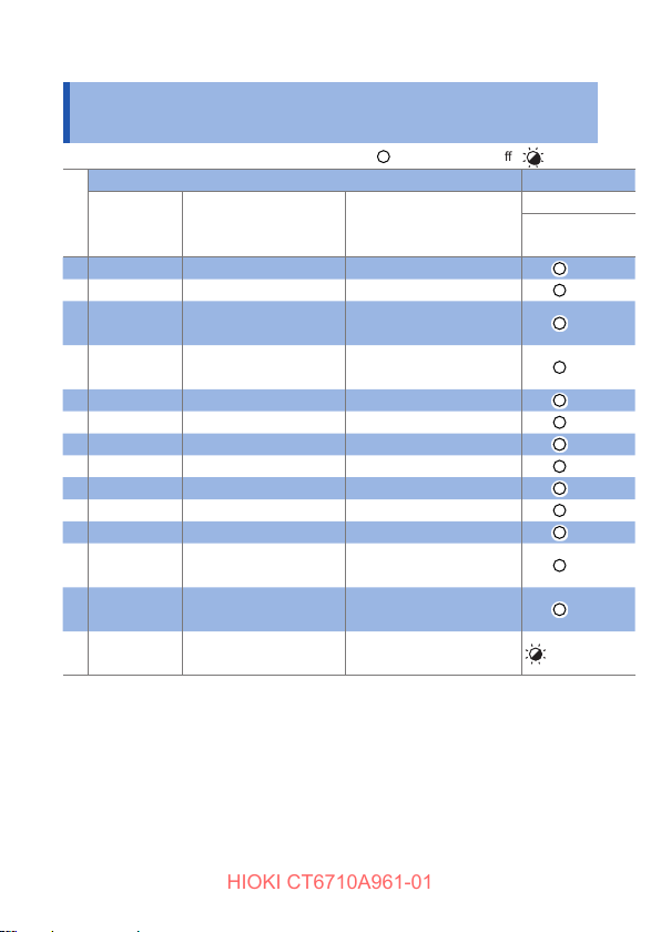
Specications of Lighting Up / Blinking LEDs
HIOKI CT6710A961-01
1.4 Specications of Lighting Up /
Blinking LEDs
: Lighting up : O : Blinking
Device state LED
Automatic
zero-
adjustment
1 − − (On start-up)
2 Not performed Not detected (Initial state)
In execution
3
(Incl. demag.)
In execution
4
(excl. demag.)
5 Completed Not detected (Before use, normal state )
6 Completed Exceeds prescribed level −
7 Not performed Exceeds prescribed level −
8 Completed Not detected Upper jaw unlocked
9 Completed Exceeds prescribed level Upper jaw unlocked
10 Not performed Not detected Upper jaw unlocked
11 Not performed Exceeds prescribed level Upper jaw unlocked
12 − *1 *1
13 − −
14 − −
Overload Others
− (No range keys available)
− (No range keys available)
Excess heat detected in
junction box*
ROM checksum error at
power-on (CPU failure)
2
*1. When the DEMAG / AUTO ZERO key is pressed under any one of the
following conditions (p. 91):
• The upper jaw is unlocked.
• An overload has been detected whether or not the upper jaw is locked
in place.
• A current exceeding 0.5 A rms has been detected whether or not the
upper jaw is locked in place.
*2. Press any key to restore the device. The ranges cannot be switched until
the device is restored.
See “When the device has entered protection mode” (p. 62).
Green
POWER
Rapidly
22
Page 29
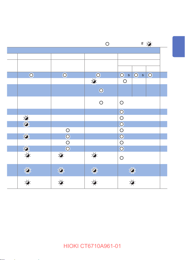
Specications of Lighting Up / Blinking LEDs
HIOKI CT6710A961-01
: Lighting up : O : Blinking
Red Red Orange Green
OVERLOAD JAW UNLOCKED
1 s 1 s 1 s 1 s 1 s 1 s 1
LED
DEMAG / AUTO
ZERO
Slowly*
30 A 5 A 0.5 A
4
RANGE
3
Rapidly*
3
Rapidly*
3
Rapidly*
3
Rapidly*
Rapidly
ashes 3 times
Rapidly
Rapidly
*3. Blinks at 250-ms intervals. (duty ratio: 50%)
*4. After the device is turned on and then all LEDs light up for 1 second, the
DEMAG / AUTO ZERO LED blinks, which indicates that demagnetization
or automatic zero-adjustment has not yet been performed.
*5. Even when demagnetization or automatic zero-adjustment has not yet
been performed, the device that has detected an overload and that with
the upper jaw unlocked leave the DEMAG / AUTO ZERO LED unlit.
Rapidly
ashes 3 times
Rapidly
Rapidly
5
*
5
*
Rapidly
ashes 3 times
Rapidly
Rapidly
Specied range only 4
Specied range only 5
Specied range only 6
Specied range only 7
Specied range only 8
Specied range only 9
Specied range only 10
Specied range only 11
Specied range only 12
Rapidly 13
Rapidly 14
1
2
3
23
Page 30

Specications of Lighting Up / Blinking LEDs
HIOKI CT6710A961-01
24
Page 31

Current Measurement
HIOKI CT6710A961-01
2
Do not clog the vents on the sides and bottom
of the termination unit (p. 16).
Doing so could cause internal overheating of the
termination unit, resulting in bodily injury, re, or
damage to the device.
Do not pile the junction box (p. 18) on
another.
Do not cover the junction box with a cloth.
Doing so could cause internal overheating of the
junction box, resulting in bodily injury, re, or damage to
the device.
IMPORTANT
Do not drop the device.
Do not subject the device to an impact.
Do not place any foreign object between the facing
core surfaces of the sensor heads.
Do not scratch the facing core surfaces between the
sensor heads.
Do not touch the facing core surfaces.
Do not insert any foreign object into the gap around
the sensor heads.
Doing so could adversely aect the measurement
accuracy and the retracting/extending mechanism.
WARNING
2
25
Page 32

Inspecting the Device Before Use
HIOKI CT6710A961-01
2.1 Inspecting the Device Before Use
Check the device for any damage that may have occurred
during storage or shipping, and verify proper operation
before use. If you nd any damage or failure, contact your
authorized Hioki distributor or reseller.
See “Before sending back your device for repair” (p. 85).
Items to prepare
• Model CT6710/CT6711 Current Probe
• Model 3269 Power Supply (available as an option)
• Waveform measuring instrument (such as oscilloscope
and recorder)
Connecting the CT6710/CT6711 to a Hioki Memory HiCorder
with a power supply module for current probes (option)
installed allows the CT6710/CT6711 to operate without the
3269 Power Supply. For more information, contact your
authorized Hioki distributor or reseller.
IMPORTANT
Use a waveform measuring instrument (such as
oscilloscope and recorder) with an input impedance of
1 MΩ or more.
The output of the device is internally terminated.
Accurate measurement is not possible with waveform
measuring instruments with an input resistance of
50
.
Ω
26
Page 33

Inspecting the Device Before Use
HIOKI CT6710A961-01
Inspecting appearance and functionality of
the device and condition of conductors to be
measured
Are the sensor, junction
box, and termination
unit damaged?
No
Yes
ZHave the device repaired.
Damage can cause
electric shock.
2
Is the insulation of each
cord damaged?
No
Provide power to the device. (p. 29)
Do the seven LEDs
light up for about one
second after the device
is turned on?
Yes
Is the insulation of
each conductor to be
measured damaged?
No
The inspection is
completed.
Yes
O or
blinking
Yes
ZHave the device repaired.
Damage can cause
electric shock.
ZHave the device repaired.
The device is damaged.
Do not clamp the sensor
around any damaged
conductor.
27
Page 34

Preparing for Measurement
HIOKI CT6710A961-01
2.2 Preparing for Measurement
WARNING
Turn o all equipment before connecting the
device.
Failure to do so can cause electric shock or a short-
circuit.
CAUTION
Before connecting the power cord to the inlet
on the rear panel of the 3269 Power Supply,
verify that the supply voltage you plan to use
falls within the supply voltage range noted on
the 3269.
Supplying a voltage that falls outside the specied
range to the 3269 could damage the CT6710/CT6711 or
the 3269, causing bodily injury.
NOTICE
Always operate the opening lever to retract,
extend, and lock the upper jaw.
If you retract, extend, or lock the upper jaw directly by
hand, the sensor may be damaged.
28
Page 35

Preparing for Measurement
HIOKI CT6710A961-01
Providing power to the CT6710/CT6711
IMPORTANT
Do not allow the total consumption current of the
current sensors connected with the 3269 Power
Supply to exceed the rated output current of the 3269.
The consumption current of the CT6710/CT6711
depends on current under measurement. One unit
of the 3269 can simultaneously provide power to up
to two current probes (the CT6710/CT6711) each of
which measures a current with the maximum rated
current value. For information about the consumption
current, see “Consumption current” (p. 81) in “Typical
Characteristics.”
The 3272 Power Supply, which does not have sucient
current capacity, cannot activate the CT6710/CT6711.
2
29
Page 36

Preparing for Measurement
HIOKI CT6710A961-01
How to provide the power to the CT6710/CT6711
Ensure that the POWER switch of the 3269
1
Power Supply is set to OFF.
Connect the power cord to the power inlet on the
2
back of the 3269 Power Supply.
Slide the opening lever
3
of the sensor toward the
lower jaw until the JAW
UNLOCKED indicator is
hidden.
The upper jaw will be locked
in place.
Do not clamp the sensor around any
conductor.
Connect the power plug
4
of the CT6710/CT6711 to
the power receptacle of
the 3269 Power Supply.
30
Power receptacle
Page 37

Preparing for Measurement
HIOKI CT6710A961-01
Set the POWER switch of the 3269 Power Supply
5
to the ON position.
The LEDs of the CT6710/CT6711 and the 3269 will light up
or blink as follows:
Model 3269
The POWER indicator will light up.
Model CT6710/CT6711
All LEDs will light up for 1 s, and then the CT6710/
CT6711 will operate as follows:
• The POWER LED will light up.
• The DEMAG / AUTO ZERO LED will blink slowly.
Green will light up
Orange will blink slowly
Keep the upper jaw locked in place while the
POWER LED lights up.
2
31
Page 38

Preparing for Measurement
HIOKI CT6710A961-01
Wait for 30 minutes or more.
6
Wait at least 30 minutes after starting to supply power
to the CT6710/CT6711 to accurately measure a current
before executing demagnetization and automatic zeroadjustment. See “Executing demagnetization and automatic
zero-adjustment” (p. 33).
Do not execute demagnetization and
automatic zero-adjustment or measure current
immediately after starting to supply power to
the CT6710/CT6711.
An oset voltage may increase due to the heat
generation of the CT6710/CT6711.
32
Page 39

Preparing for Measurement
HIOKI CT6710A961-01
Executing demagnetization and automatic zeroadjustment
WARNING
Do not hold down the DEMAG / AUTO ZERO
key when the sensor is clamped around a
conductor under measurement.
Conductor
under measurement
Do not hold down the key.
Doing so will start magnetization, causing bodily injury
or damage to the circuit under measurement.
2
33
Page 40

Preparing for Measurement
HIOKI CT6710A961-01
Do not subject the connection to force.
Do not rotate the output terminal while the
termination unit is connected with a waveform
measuring instrument.
Doing so could damage the output terminal on the
termination unit or the BNC input terminal on the
waveform measuring instrument.
Do not short-circuit the output terminal
Do not apply voltage to the output terminal.
Doing so could damage the device.
NOTICE
34
Page 41

Preparing for Measurement
HIOKI CT6710A961-01
NOTICE
Arrange the termination unit and a BNC
input terminal of your waveform measuring
instrument in a straight line when connecting
the termination unit.
Failure to do so may damage the output terminal.
When connecting the output terminal to an
input terminal that is not a BNC terminal
through a conversion plug, make sure that the
polarity is as follows:
BNC center contact: Positive
Outer conductor: Ground potential
(or negative)
Failure to do so may damage the device and your
waveform measuring instrument.
2
35
Page 42

Preparing for Measurement
HIOKI CT6710A961-01
What is demagnetization?
The magnetic core can be magnetized, which results
from turning power on and o, inputting an excessively
large current, or other factors. Executing demagnetization
eliminates magnetic charges.
What is automatic zero-adjustment?
Automatic zero-adjustment corrects variations in the oset
voltage caused by factors such as the device-specic
oset voltage and variations in temperature.
When the DEMAG / AUTO ZERO LED blinks slowly,
execute demagnetization and automatic zero-adjustment.
The DEMAG / AUTO ZERO LED blinks slowly in the
following states:
• The power supply to the CT6710/CT6711 just started.
• A current exceeding the rated current was inputted to
the device, but this condition was resolved. (The current
value fell below the rated value or stopped. Otherwise,
the sensor was removed from the conductor under
measurement.)
During demagnetization (with the DEMAG / AUTO ZERO
LED lit), the device outputs a demagnetization waveform
(which attenuates over time) from its output terminal.
This waveform, which appears on a waveform measuring
instrument, may be asymmetric along the horizontal axis;
however, this does not represent a device malfunction.
36
Page 43

Preparing for Measurement
HIOKI CT6710A961-01
How to execute demagnetizing and automatic
zero-adjustment
IMPORTANT
Do not move the sensor during demagnetization or
automatic zero-adjustment.
Disturbance (such as external magnetic elds and
temperature changes) may prevent demagnetization
or automatic zero-adjustment from being completed
normally.
Slide the opening lever
1
of the sensor toward the
lower jaw until the JAW
UNLOCKED indicator is
hidden.
The upper jaw will be locked
in place.
The JAW UNLOCKED LED
will go out.
2
Set the input coupling of your waveform
2
measuring instrument to GND, then adjust the
zero position of the display.
Do not clamp the sensor around any
conductor.
37
Page 44

Preparing for Measurement
HIOKI CT6710A961-01
Set the input coupling of the waveform
3
measuring instrument to DC.
Connect the output
4
terminal of the
termination unit to a
BNC input terminal of
the waveform measuring
instrument.
• Insert the output terminal
straight.
• Insert the output terminal
until it clicks so that it is
securely locked in position.
The connection can be established with the unlock lever of
the termination unit pointing up, regardless of whether the
pair of the locking studs in the BNC input terminal on the
waveform measuring instrument is xed in the horizontal or
vertical orientation.
38
Vertical Horizontal
Page 45

Hold down the DEMAG /
HIOKI CT6710A961-01
5
AUTO ZERO key on the
junction box for about 1
second.
Preparing for Measurement
The DEMAG / AUTO ZERO LED will light up.
Demagnetization and automatic zero-adjustment will
start.
After the completion, the DEMAG / AUTO ZERO LED
will go out.
Green will light up
Orange will light up
Green will light up
Orange will go out
Hold down
2
39
Page 46

Preparing for Measurement
HIOKI CT6710A961-01
If the DEMAG / AUTO ZERO LED ashes three times, the
device cannot perform demagnetization or automatic zeroadjustment.
ZImplement the remedy described on the following page.
“Demagnetizing / automatic zero-adjustment
unavailable” (p. 92)
To halt demagnetization or automatic zero-adjustment
on the middle of its execution
ZPull the unlock lever toward you to unlock the upper
jaw.
When you halt demagnetization or automatic zeroadjustment, re-execute demagnetization and automatic
zero-adjustment before taking a measurement.
To execute automatic zero-adjustment alone (without
executing demagnetization)
ZPress the DEMAG / AUTO ZERO key momentarily (Do
not hold down the key). (p. 18)
40
Page 47

Measuring Currents
HIOKI CT6710A961-01
2.3 Measuring Currents
Be sure to read the following sections and perform the steps
described there before taking measurements:
“2.1 Inspecting the Device Before Use” (p. 26)
“2.2 Preparing for Measurement” (p. 28)
Follow all operating precautions for your waveform
measuring instrument or any other measuring instrument.
DANGER
Do not cause a short-circuit between the wire
to be measured and another wire with the
metallic parts of the tips of the sensor.
Doing so can cause arc ash, resulting in serious bodily
injury or damage to the device or other equipment.
Do not measure any current in excess of the
derating curve.
Doing so can cause overheating of the device, resulting
in bodily injury, re, or damage to the device.
See “Frequency derating curve” (p. 78).
The maximum measurement current varies with the
frequency, and the current that can be measured
continuously is limited. Operating the device at less than
this limitation is referred to as derating.
2
41
Page 48

Measuring Currents
HIOKI CT6710A961-01
Do not subject the ground side of other input
terminals to a dierent potential when you
use one of the following waveform measuring
instruments:
• an instrument that does not provide
electrical insulation between its input
terminals and chassis
• an instrument that does not provide
electrical insulation among its input
terminals
H
Power source
Load
DANGER
L
Waveform measuring
instrument
Load
Model 3269
Power Supply
If you do so, a short-circuit current will ow through the
3269 Power Supply and the CT6710/CT6711 from the
ground terminal, causing electric shock or damage to
the CT6710/CT6711 and the 3296.
See the gure in “Example of connection to the circuit to be
measured” (p. 49) for a proper connection.
42
Page 49

Measuring Currents
HIOKI CT6710A961-01
DANGER
Ensure that the insulation on a conductor is
not worn or damaged before clamping the
sensor around the conductor to be measured.
Take care not to damage the insulation when
clamping the sensor around the conductor.
Damage to the conductor insulation can cause electric
shock.
Connect the CT6710/CT6711 to the 3269 Power
Supply and a waveform measuring instrument
(oscilloscope or recorder) before clamping the
device around a live line to be measured.
Failure to do so may cause electric shock or a short-
circuit.
2
43
Page 50

Measuring Currents
HIOKI CT6710A961-01
While measuring a high-frequency current
or a current that includes high-frequency
components, keep hands and other body
parts away from the jaws.
Eddy current loss may cause heating of the sensor
heads. Failure to do so could re or damage to the
measurement target and device, resulting in burns.
Keep away any cords and other parts, which
include the cords of the device, from the
conductor under measurement.
Dielectric heating may cause heating of cords and other
parts, resulting in burns.
WARNING
44
Page 51

Measuring Currents
HIOKI CT6710A961-01
CAUTION
Do not place any conductor carrying a current
with a frequency of 10 kHz or more close to
the jaws even when the sensor is not clamped
around a conductor.
A current owing through conductors near the sensor
may heat up the sensor heads, leading to damage to
the device, resulting burns.
When the device is clamped around one of the goand-return conductors and the other conductor is
placed close to the jaws, self-heating of both currents
will synergistically heat up the sensor heads even if
the electric current is lower than the maximum rated
current.
Do not place conductors
not to be measured close
to the jaws.
2
45
Page 52

Measuring Currents
HIOKI CT6710A961-01
Do not prevent heat radiation from the device.
Do not input a current that exceeds the
maximum rated current value*.
An temperature increase in the device cause burns,
damage to the device, or a short-circuit.
Never input a current that exceeds ±50 A even
momentarily.
Doing so can damage the device, resulting in bodily
injury.
See “Maximum peak current” (p. 72).
Do not exceed the maximum rated current,
regardless of the blinking state of the
OVERLOAD LED.
Doing so can damage the device, resulting in bodily
injury.
Overload warnings are detectable in a frequency band
of DC and 45 Hz to 66 Hz (sine wave). When measuring
a current with a frequency outside the frequency
detection band, the overload warning function may not
work properly.
See “Frequency characteristics” (p. 77).
CAUTION
* The maximum rated current has been specied in
light of a temperature increase caused by self-heating
during measurement. The maximum rated current
varies depending on the frequency of the current under
measurement.
See the gures in “Frequency derating curve” (p. 78).”
46
Page 53

Measuring Currents
HIOKI CT6710A961-01
CAUTION
Use the device for measuring currents much
lower than the maximum rated current value if
an ambient temperature is relatively high or a
current to be measured can contain frequency
components other than the fundamental.
Self-heating could cause burns or damage to the device
even if the current under measurement is lower than the
maximum rated current.
The maximum rated current is dened as a
recommended value for when a sine-wave current is
inputted to the device at the temperatures and humidity
specied for the guaranteed accuracy.
See “Frequency derating curve” (p. 78).
Connect the device and other probes properly
to a circuit to be measured and your waveform
measuring instrument.
Improperly connecting them could cause electric shock
or damage to the device, other probes, and instrument.
2
47
Page 54

Measuring Currents
HIOKI CT6710A961-01
Do not subject the sensor to high voltage,
including static electricity.
Doing so may damage the device.
Do not pass a current through a conductor
under measurement when the 3269 Power
Supply or your waveform measuring
instrument is o.
Doing so may damage the device and instrument.
Keep the upper jaw locked in place except the
following occasions:
• When clamping the sensor around a
conductor to be measured
• When removing the sensor from the
conductor.
Leaving the upper jaw unlocked can damage the device.
NOTICE
48
Page 55

Measuring Currents
HIOKI CT6710A961-01
Example of connection to the circuit to be
measured
The gure below illustrates a connection between the device and a
measuring instrument with non-isolated input terminals equipped,
such as a general oscilloscope.
Waveform measuring instrument
H
Power source
Load Load
L
Model 3269 Power Supply
The 3269 Power Supply can provide the power to up to two
probes of the CT6710/CT6711.
Connecting the CT6710/CT6711 to a Hioki Memory HiCorder
with a power supply module for current probes (option)
installed allows the CT6710/CT6711 to operate without the
3269 Power Supply. For more information, contact your
authorized Hioki distributor or reseller.
2
49
Page 56

Measuring Currents
HIOKI CT6710A961-01
How to measure a current
IMPORTANT
Do not place the sensor close to a heat source.
Do not roughly operate the opening lever to lock the
upper jaw.
Do not subject the jaws and opening lever to force.
Do not subject the sensor aperture to force while the
sensor is clamped around the conductor.
Changes in ambient temperature and an impact
on the sensor head can cause uctuations in the
oset voltage, resulting in an adverse eect on the
measurement accuracy.
Be sure to execute demagnetization and automatic
zero-adjustment before taking measurements.
Failure to do so can adversely aect the measurement
accuracy.
See “Executing demagnetization and automatic zeroadjustment” (p. 33).
50
Page 57

Pull the opening lever of
HIOKI CT6710A961-01
1
the sensor toward you to
retract the upper jaw.
Clamp the sensor
2
around a conductor to be
measured.
• Have the current direction
indicator match the
direction of the current to be
measured.
• Place the conductor at
the center of the sensor
aperture.
Slide the opening lever
3
toward the lower jaw until
the JAW UNLOCKED
indicator is hidden.
The upper jaw will be locked
in place.
The JAW UNLOCKED LED
will go out.
Measuring Currents
2
Low-potential side
(Ground potential
side)
High-
potential side
51
Page 58

Measuring Currents
HIOKI CT6710A961-01
Check the LEDs on the junction box.
4
The POWER LED
and one of
light up.
There is no error.
Go on to step
Z
.
5
The OVERLOAD LED blinks rapidly.
The device has detected a measurement current in excess
of the level dened for the current range.
See “Overload” (p. 90).
When you use the 30 A range
Immediately remove the sensor from the conductor
Z
under measurement.
When you use the 0.5 A range or 5 A range
Switch a higher current range.
Z
IMPORTANT
• The instrument may be unable to properly detect
overload states immediately after the current range has
changed.
• The currents for which an overload state can be detected
are DC and sine waves with frequencies of 45 Hz to
66 Hz. The device is unable to detect the currents listed
below as an overload state.
- Currents that exceed the dened level on a
momentary basis
- High-frequency currents that exceed the dened level
the RANGE LEDs
Any other LEDs lights up or blinks.
A dierent error is occurring.
See “4.2 Errors” (p. 88) to identify a reason and take
Z
necessary measures.
52
Page 59

Measuring Currents
HIOKI CT6710A961-01
Press the (higher range) key or (lower range)
5
key to choose a current range.
• Choose a current range with a maximum peak
current higher than the peak value of a current under
measurement.
See “Maximum peak current” (p. 72).
If the peak value of the current under measurement
exceeds the maximum peak current of the chosen current
range, the output waveform will be saturated or distorted,
preventing you from correctly observing the current
waveform.
• You need to choose a current range according to the level
of the current under measurement to minimize an adverse
eect of noise on observation of the current waveform. The
following table shows the recommended current ranges for
each of the levels of currents under measurement.
Electric current level
Recommended current
±5 A to ±50 A 30 A (0.1 V/A)
±0.5 A to ±5 A 5 A (1 V/A)
±1 mA to ±0.5 A 0.5 A (10 V/A)
range
(Output rate)
2
53
Page 60

Measuring Currents
HIOKI CT6710A961-01
Convert a voltage sensitivity of the waveform
6
measuring instrument into a current sensitivity.
Using the following formula can convert a voltage sensitivity
(unit: V/div) specied on the waveform measuring instrument
into a current sensitivity (unit: A/div).
S
=
S
/
R
I
V
O
S
: Current sensitivity (A/div)
I
S
: Voltage sensitivity (V/div)
V
R
: Output rate (V/A)
O
Example
When your waveform measuring instrument with its voltage
sensitivity set at 10 mV/div measures a current that has an
RMS value of 1 mA
1 mA/div
0.5 A range (10 V/A) 5 A range (1 V/A)
S
= (10 ×10-3) / 10
I
= 1 × 10
-3
(A/div) = 10 ×10-3 (A/div)
S
I
54
10 mA/div
= (10 × 10-3) / 1
Page 61

Measuring Currents
HIOKI CT6710A961-01
IMPORTANT
After you measured a current that exceeds the
maximum rated current value of each current range,
re-execute the demagnetization and automatic zeroadjustment.
The sensor heads have been magnetized, causing
incorrect current measurements.
See “Executing demagnetization and automatic zeroadjustment” (p. 33).
IMPORTANT
When you measure high-frequency currents, the position of the
conductor under measurement in the sensor aperture may vary
the magnitude of load applied to the circuit under measurement,
adversely aecting the measurement accuracy.
See “Input impedance” (p. 80).
The following methods can minimize the adverse eect:
• Straighten the conductor under measurement as long as
possible.
• Clamp the sensor at the center of the straight portion of the
conductor as close as possible.
• Arrange the conductor at the center of the sensor aperture as
close as possible.
• Do not wind the conductor around a jaw.
2
55
Page 62

Measuring Currents
HIOKI CT6710A961-01
IMPORTANT
When you measure high-frequency currents, Clamping the
sensor around the high-potential side of a circuit may cause
common-mode noise to aect the measurement accuracy
adversely.
See “Inuence of common-mode voltage” (p. 82).
As needed, reduce the frequency band of the waveform
measuring instrument, or clamp the sensor around the lowpotential side conductor.
H
NO
Power
source
Load
L
Displayed values can frequently uctuate due to induction
potential even when no voltage is applied. This, however, is
not a malfunction.
56
OK
Page 63

Measuring Currents
HIOKI CT6710A961-01
NOTE
• Depending on the amplitude and frequency of a current
under measurement, the sensor heads may emit a
resonant sound. Such a sound may also be emitted during
demagnetization. This, however, does not represent a
device malfunction.
• If foreign matter adheres to the facing core surfaces on
the sensor heads and thus creates a slight gap between
the upper and lower sensor heads, the sensor heads may
emit a resonant sound.
ZRemove any foreign matter by following the cleaning
method.
See “4.3 Cleaning” (p. 96).
• An increase in the resonant sound while the device is in
use may indicate that the gap between the upper and
lower heads has widened. The gap may adversely aect
the measurement accuracy. Calibrating the device is
recommended.
See “Maintenance and Service” (p. 83).
2
57
Page 64

Measuring Currents
HIOKI CT6710A961-01
To measure a low current
When measuring low DC or low-frequency low AC, you can
increase the current-detection sensitivity of the device in the
following way.
How to measure a low current
Coil a single conductor to be measured into
1
several loops with a diameter of 200 mm or
more.
Clamp the sensor around the loops in a bundle.
2
This will make the conductor pass through the sensor
aperture one time more than the loop count consecutively
in one direction.
Arrange the loops radially as shown on the
3
following page.
Measure the current.
4
58
Page 65

Measuring Currents
HIOKI CT6710A961-01
As shown in the gure below, clamping the sensor around
the seven loops in a bundle allows the conductor to pass
through the sensor aperture eight times, which increases the
voltage of the output signal by a factor of eight.
200 mm or more
Arrange loops radially.
φ
2
High-potential
side
Low-potential
side
(Grounded side)
59
Page 66

Measuring Currents
HIOKI CT6710A961-01
To measure a current accurately
Retracting and extending the upper jaw can cause an oset
voltage of several millivolts. Perform the steps described
below before measuring a current to measure it accurately.
How to measure a current accurately
Hold down the DEMAG /
1
AUTO ZERO key on the
junction box for about 1
second.
The DEMAG / AUTO ZERO
LED will light up.
Demagnetization and
automatic zero-adjustment will
start.
After the completion, the
DEMAG / AUTO ZERO LED
will go out.
Wait for about 5 minutes.
2
The uctuation in the oset voltage will stabilize.
Operate the opening
3
lever of the sensor back
and forth to retract and
extend the upper jaw 4
or 5 times.
60
Hold down
Before execution,
orange blinks or
goes out.
Page 67

Slide the opening
HIOKI CT6710A961-01
4
lever toward the lower
jaw until the JAW
UNLOCKED indicator is
hidden.
The upper jaw will be locked
with the upper and lower
sensor heads arranged in
position relative to each other.
The JAW UNLOCKED LED
will go out.
Momentarily press the
5
DEMAG / AUTO ZERO
key on the junction box.
(Do not hold down the
key.)
Measuring Currents
2
The DEMAG / AUTO ZERO
LED will light up.
Automatic zero-adjustment
will be performed alone.
After the completion, the
DEMAG / AUTO ZERO LED
will go out.
Measure a current.
6
See “How to measure a current” (p. 50).
Press
(Do not hold down)
61
Page 68

Measuring Currents
HIOKI CT6710A961-01
When the device has entered protection mode
To protect the device against self-generated heat, it enters
protection mode when the temperature of the junction box
exceeds a specied level.
Green lights up
Reds blink rapidly
Orange blinks rapidly
Greens blink rapidly
In protection mode, the device cannot correctly measure any
current. Moreover, you cannot switch the current ranges.
When the device has entered protection mode, follow the
procedure presented on the following pages to restore it to
normal operation.
If the device has entered protection mode, it is
recommended to re-calibrate it because internal components
may have been subjected to thermal stress.
62
Page 69

How to restore the device
HIOKI CT6710A961-01
Pull the opening lever of
1
the sensor toward you
to retract the upper jaw,
and remove the sensor
from the conductor
under measurement.
Slide the opening
2
lever toward the lower
jaw until the JAW
UNLOCKED indicator is
hidden.
The upper jaw will be locked
in place.
Wait for a while to let the junction box cool down
3
to a normal temperature.
Measuring Currents
2
63
Page 70

Measuring Currents
HIOKI CT6710A961-01
Press any key.
4
One of the RANGE LEDs (of
the range used before the
device entered protection
mode) will light up, and the
device will get back to normal.
The DEMAG / AUTO ZERO
LED will blink slowly.
Perform demagnetization
5
and automatic zeroadjustment.
See “Executing
demagnetization and
automatic zero-adjustment”
(p. 33).
Press
any key
64
Page 71

Finishing Measurement
HIOKI CT6710A961-01
2.4 Finishing Measurement
NOTICE
Do not pull the cord to unplug the output
terminal.
Doing so can damage the cord and output terminal.
Hold the termination unit and disconnect the
output terminal while pulling the unlock lever
toward you.
2
65
Page 72

Finishing Measurement
HIOKI CT6710A961-01
To disconnect the power plug of the device,
do not pull the cord.
Do not twist the power plug.
Doing so could damage the cord and the power
receptacle of the 3269 Power Supply.
While holding the shell (p. 17), pull the
power plug out.
Pulling the shell lets the plug be unlocked, so you can
disconnect the plug from the power receptacle.
NOTICE
66
Page 73

How to nish measurement
HIOKI CT6710A961-01
Pull the opening lever of
1
the sensor toward you
to retract the upper jaw,
and remove the sensor
from the conductor
under measurement.
Slide the opening
2
lever toward the lower
jaw until the JAW
UNLOCKED indicator is
hidden.
The upper jaw will be locked
in place.
The JAW UNLOCKED LED
will go out.
Disconnect the
3
termination unit from the
BNC input terminal on
the waveform measuring
instrument.
Finishing Measurement
2
While pulling the unlock lever,
pull out the termination unit
straight.
67
Page 74

Finishing Measurement
HIOKI CT6710A961-01
Set the POWER switch of the 3269 Power Supply
4
in the OFF position.
Disconnect the power
5
plug of the CT6710/
CT6711 from the 3269
Power Supply.
Hold the shell (p. 17) of
the power plug when you
disconnect it.
Do not pull the cord.
Do not twist the power plug.
Unplug the power cord of the 3269 Power Supply
6
from the outlet.
68
Page 75

Specications
HIOKI CT6710A961-01
3
Unless otherwise specied, each specication item is applied to
both Model CT6710 and Model CT6711.
Items with a model number, “(Model CT6710)” or “(Model CT6711),”
indicated are applicable to each model.
Each item is specied for the device operated at 23°C±5°C
(73°F±9°F) and 80% RH (no condensation), 30 minutes elapses
after the device is turned on before use.
3.1 General Specications
Operating environment
Indoor, Pollution Degree 2, Operating altitude
up to 2000 m (6562 ft.)
Operating temperature and humidity
0°C to 40°C (32°F to 104°F), 80% RH or less
(no condensation)
Storage temperature and humidity range
−10°C to 50°C (14°F to 122°F), 80% RH or less
(no condensation)
Standards Safety: EN61010
EMC: EN61326
Measurable conductors
Insulated conductors
Measurable diameter of conductors
5 mm or less in diameter
3
69
Page 76

General Specications
HIOKI CT6710A961-01
Power supply External power supply (Model 3269)
Rated supply voltage: ±12 V DC ±0.5 V
Maximum rated power: 7.8 VA
(For current probe only, when measuring
30 A rms continuously)
Consumption current
See “Consumption current” (p. 81) in “3.4
Typical Characteristics.”
Dimensions • Sensor
Approx. 155W × 18H × 26D mm
(6.10″W × 0.71″H × 1.02″D)
• Junction box
Approx. 45W × 120H × 25D mm
(1.77″W × 4.72″H × 0.98″D)
• Termination unit
Approx. 29W × 83H × 40D mm
(1.14″W × 3.27″H × 1.57″D)
Excluding BNC connector or protrusions
Mass Approx. 370 g (13.1 oz.)
Cord lengths • Between sensor and junction box
Approx. 1500 mm (59.06″)
• Between junction box and termination unit
Approx. 150 mm (5.91″)
• Power cord
Approx. 1000 mm (39.37″)
Product warranty period
1 year
Accessories
Option
See “(Accessory)” (p. 5) and “Option”
(p. 6).
70
Page 77

Specications of Input, Output, and Measurement
HIOKI CT6710A961-01
3.2 Specications of Input, Output, and
Measurement
Basic specications
Frequency band
DC to 50 MHz (−3 dB) (Model CT6710)
DC to 120 MHz (−3 dB) (Model CT6711)
See “Frequency characteristics” (p. 77) in “3.4
Typical Characteristics.”
Rise time (10% to 90%)
7.0 ns or less (Model CT6710)
2.9 ns or less (Model CT6711)
Delay time (the time lag between the input signal with a rise
time of 1 ns and the output signal)
30 A range: 12 ns (typical)
5 A range: 12 ns (typical)
0.5 A range: 13 ns (typical)
Current range (output rate)
30 A range (Rate: 0.1 V/A)
5 A range (Rate: 1 V/A)
0.5 A range (Rate: 10 V/A)
3
71
Page 78

Specications of Input, Output, and Measurement
HIOKI CT6710A961-01
Maximum rated current*
Maximum peak current
Noise 75 µA rms or less (Typical: 60 µA rms)
Input impedance
*1. Depending on the ambient temperature and measurement
conditions, internal overheating can result in an overload
condition, limiting the maximum rated current lower than those
specied here.
*2. The device requires to cool down for 10 times the length of time
the current was inputted.
1
30 A range: 30 A rms
5 A range: 5 A rms
0.5 A range: 0.5 A rms
Derating is needed as input frequency
increases.
See “Frequency derating curve” (p. 78) in “3.4
Typical characteristics.”
Specied for currents of DC and sine wave
30 A range: ±50 A peak
(maximum duration of input: 2 s*2)
5 A range: ±7.5 A peak
0.5 A range: ±0.75 A peak (less than 10 MHz)
±0.3 A peak (10 MHz or more)
(For only the probe with the 0.5 A range,
connected with a measuring instrument that has
a frequency band of 20 MHz)
See “Input impedance” (p. 80) in “3.4 Typical
characteristics.”
72
Page 79

Specications of Input, Output, and Measurement
HIOKI CT6710A961-01
Specications of accuracy
Accuracy warranty conditions
• Accuracy warranty period
1 year (until the upper jaw has been retracted
and locked up to 10,000 cycles)
• Guaranteed accuracy period after adjustment
made by Hioki
0.5 year
• Temperature and humidity for guaranteed
accuracy
23°C±5°C (73°F±9°F), 80% RH or less
• Warm-up time
At least 30 minutes
• Power voltage range
±12 V DC ±0.5 V
Amplitude accuracy*
*3. Unless there is any change in the state of the facing core
surfaces, which includes scratches, adhesion of foreign objects,
or any change in the operating environment.
3
30 A range: ±3.0% rdg. ±1 mV
(Typical: ±1.0% rdg. ±1 mV
[for 10 A rms or less])
5 A range: ±3.0% rdg. ±1 mV
(Typical: ±1.0% rdg. ±1 mV)
0.5 A range: ±3.0% rdg. ±10 mV
(Typical: ±1.0% rdg. ±10 mV)
For a direct current and a sine-wave current
with frequencies of 45 Hz to 66 Hz within the
maximum peak current value of each current
range
3
73
Page 80

Specications of Input, Output, and Measurement
HIOKI CT6710A961-01
Temperature characteristics of sensitivity*
±2.0% rdg. or less
After automatic zero-adjustment was executed,
in the temperature range except 23°C±5°C,
under the following input conditions:
30 A range: AC with 50 Hz, 30 A
5 A range: AC with 50 Hz, 5 A
0.5 A range: AC with 50 Hz, 0.5 A
Eect of radiated radio-frequency electro-magnetic eld
±10 mA or less at 3 V/m
Eect of conducted radio-frequency electro-magnetic eld
±10 mA or less at 3 V
Eect of external magnetic eld
20 mA or less (Model CT6710)
(DC and 60 Hz, in a magnetic eld of
400 A/m)
5 mA or less (Model CT6711)
(DC and 60 Hz, in a magnetic eld of
400 A/m)
*3. Unless there is any change in the state of the facing core
surfaces, which includes scratches, adhesion of foreign objects,
or any change in the operating environment.
*4. The values of the temperature characteristics of sensitivity are
added to the amplitude accuracy.
3, *4
74
Page 81

Specications of Functionality
HIOKI CT6710A961-01
3.3 Specications of Functionality
Demagnetizing and automatic zero-adjustment functions
When the upper jaw is not locked in place, an
overload is detected, or an inputted current
exceeds the values listed below, the functions
are not available.
0.50 ±0.25 A rms
(DC and sine wave with frequencies of 45 Hz
to 66 Hz)
• Demagnetizing and automatic zero-adjustment
Operation: Executes demagnetization and
automatic zero-adjustment.
Means: Hold down the DEMAG / AUTO
ZERO key (1 s).
• Automatic zero-adjustment
Operation: Executes automatic zero-
adjustment alone.
Means: Press the DEMAG / AUTO ZERO
key.
Jaw-unlocked detection
When the upper jaw is not locked in place, the
JAW UNLOCKED LED lights up.
3
75
Page 82

Specications of Functionality
HIOKI CT6710A961-01
Overload detection
• Typical sampling frequency: 7.8125 kHz
• Typical checking cycle: 500 ms
Breakdown
Typical sampling period: 400 ms
Typical computing-and-judging period:
100 ms
(1) Excess of rated current level
When the input current exceeds the following
level, the OVERLOAD LED blinks rapidly.
30 A range: 32.5 ±2.5 A rms
5 A range: 5.25 ±0.25 A rms
0.5 A range: 0.525 ±0.025 A rms
(For all the ranges, the target currents are of
DC and sine wave with frequencies of 45 Hz
to 66 Hz)
(2) Excess of specied temperature
Detects an internal temperature anomaly and
issues an alert by blinking all of the LEDs
except the POWER LED.
Typical specied-temperature: 80°C
Typical hysteresis: 10°C
Recovery means: Press any key. Then,
the device requires
demagnetization and
automatic zero-adjustment.
Specications of lighting up / blinking LEDs
See “1.4 Specications of Lighting Up / Blinking
LEDs” (p. 22).
76
Page 83

Typical Characteristics
0.5 A range (10 V/A)
Gain (dB)
Frequency
(Hz)
0.5 A range (10 V/A)
HIOKI CT6710A961-01
3.4 Typical Characteristics
All of the characteristics shown in this section are typical.
Frequency characteristics
30
20
10
5 A range (1 V/A)
0
−10
Gain (dB)
30 A range (0.1 V/A)
−20
−30
−40
1 10 100 1 k 10 k 100 k 1 M 10 M 100 M
Fig. 1 Frequency characteristics (Model CT6710)
30
20
10
5 A range (1 V/A)
0
−10
30 A range (0.1 V/A)
−20
−30
−40
1 10 100 1 k 10 k 100 k 1 M 10 M 100 M
Fig. 2 Frequency characteristics (Model CT6711)
Frequency (Hz)
3
77
Page 84

Typical Characteristics
HIOKI CT6710A961-01
Frequency derating curve
Figures 3 and 4 show the derating curves with a sine-wave
current inputted in the temperature and humidity range for
the guaranteed accuracy. If the ambient temperature (T
rises or the current under measurement contains highfrequency components, the device temperature will rise, and
thus its continuously inputtable current value and frequency
will lower.
)
A
78
Page 85

Typical Characteristics
35
Maximum input current (A)
TA = 23°C, Sine wave
35
Maximum input current (A)
HIOKI CT6710A961-01
30
25
20
15
10
5
0
100 1 k 10 k 100 k 1 M 10 M 100 M 1 G
Frequency (Hz)
Fig. 3 Derating curve according to frequency (Model CT6710)
30
25
20
15
10
5
0
100 1 k 10 k 100 k 1 M 10 M 100 M 1 G
Frequency (Hz)
30 A range
5 A range
3
30 A range
5 A range
TA = 23°C, Sine wave
Fig. 4 Derating curve according to frequency (Model CT6711)
79
Page 86

Typical Characteristics
HIOKI CT6710A961-01
Input impedance
The location where the sensor is clamped will exhibit
impedance as shown in Figs. 5 and 6, which inserts a load
in a circuit under measurement. In particular, take this
characteristic into account when measuring a high-frequency
current.
1
0.1
0.01
Input impedance (Ω)
0.001
100 1 k 10 k 100 k 1 M 10 M 100 M 1 G
Fig. 5 Input impedance (Model CT6710)
1
Frequency (Hz)
0.1
0.01
Input impedance (Ω)
0.001
100 1 k 10 k 100 k 1 M 10 M 100 M 1 G
Fig. 6 Input impedance (Model CT6711)
80
Frequency (Hz)
Page 87

Consumption current
1.2
Input current (A)
HIOKI CT6710A961-01
Consumption current (A)
Fig. 7 Consumption current (with the 30 A range specied)
Typical Characteristics
1
0.8
0.6
0.4
0.2
0
0 10 20 30 40 50
DC
AC
3
81
Page 88

Typical Characteristics
V
/ V
(dB)
Frequency (Hz)
HIOKI CT6710A961-01
Inuence of common-mode voltage
The gure below indicates the ratio of common-mode
voltage (external noise voltage) applied to a conductor under
measurement positioned in the sensor aperture and the
resulting output voltage.
−40
−60
−80
−100
c
−120
O
−140
−160
−180
10 100 1 k 10 k 100 k 1 M 10 M
VO: Output voltage (V)
VC: Common-mode voltage (V)
Fig. 8 Inuence of common-mode voltage
82
0.5 A range
5 A range
30 A range
30 A range
Page 89

Maintenance and Service
HIOKI CT6710A961-01
4
WARNING
Do not attempt to modify, disassemble, or
repair the device yourself.
Attempting the above may cause bodily injury or re.
Calibration
The calibration interval depends on factors such as
operating conditions and environment.
Please determine the appropriate calibration interval based
on your operating conditions and environment and have
Hioki calibrate it accordingly on a regular basis.
4
83
Page 90

Troubleshooting
HIOKI CT6710A961-01
4.1 Troubleshooting
If damage is suspected, read “Before sending back your
device for repair” (p. 85) and check the device as
described. If this cannot resolve problems, contact your
authorized Hioki distributor or reseller.
When transporting the device, be sure to observe the
following precautions:
• Remove the CT6710/CT6711 from the 3269 Power
Supply.
• Include a memo that describes the problem in detail.
• Pack the device in the packaging in which it was initially
delivered and double-pack it.
Damage that occurs during transportation is not covered by
the warranty.
84
Page 91

Troubleshooting
HIOKI CT6710A961-01
Before sending back your device for repair
Symptom
No waveform is displayed on the waveform measuring
instrument.
Z
Z
If the issue has not been resolved, the device may be
malfunctioning.
Z
A resonant sound is emitted from the sensor heads.
This does not aect the measurement accuracy.
The sensor head may emit a resonant sound depending
on the amplitude and frequency of the current under
measurement.
The resonant sound emitted from the sensor heads
becomes louder.
Calibration of the device is recommended because the
gap may adversely aect the measurement accuracy.
The gap between the upper and lower sensor heads may
have increased.
Cause, remedy
/
Re-execute demagnetization and automatic zeroadjustment. (p. 33)
Make sure that the input coupling of the waveform
measuring instrument is set to DC. (p. 38)
Have the device repaired.
4
85
Page 92

Troubleshooting
HIOKI CT6710A961-01
Symptom
Cause, remedy
/
Demagnetization and automatic zero-adjustment
cannot be performed.
Demagnetization or automatic zero-adjustment has not
been completed normally.
Under the following conditions, demagnetizing and
automatic zero-adjustment cannot be performed.
Alternatively, demagnetization or automatic zeroadjustment has not been completed normally.
• The upper jaw is unlocked.
• An overload has been detected whether or not the
upper jaw is locked.
• A current exceeding 0.5 A rms has been detected
whether or not the upper jaw is locked.
Implement the remedy described on the following
Z
pages:
See “Demagnetizing / automatic zero-adjustment
unavailable” (p. 92).
Then, re-execute demagnetization and automatic
zero-adjustment.
See “Executing demagnetization and automatic zeroadjustment” (p. 33).
When demagnetization or automatic zero-adjustment
has not been normally completed even with the sensor
not clamped around any conductor and the upper jaw
locked in place, the device may be malfunctioning.
Send the device for repair.
Z
86
Page 93

Troubleshooting
HIOKI CT6710A961-01
Symptom
The waveform outputted during the demagnetization is
asymmetric along the horizontal axis.
This does not represent a device malfunction.
Z
Cause, remedy
/
After demagnetization and automatic zero-adjustment
are completed, make sure that the zero position on
the waveform measuring instrument is appropriate.
4
87
Page 94

Errors
HIOKI CT6710A961-01
4.2 Errors
If an error occurs, the LEDs on the junction box will light up
or blink.
See “1.4 Specications of Lighting Up / Blinking LEDs”
(p. 22).
When an error occurs, remedy the error according to
measures described on the following pages. If the device
needs to be repaired, contact your authorized Hioki
distributor or reseller.
88
Page 95

Errors
HIOKI CT6710A961-01
Types of errors
You can identify the type of an error with the LED indicators
displayed on the junction box.
Protection mode
Green lights up
Reds blink rapidly
Orange blinks rapidly
Greens blink rapidly
The abnormal internal temperature was detected in the
junction box, and thus the device has entered protection
mode.
Follow the procedure on the following page.
Z
“When the device has entered protection mode” (p. 62)
4
Calibration of the device is recommended. Internal
components may have been subject to thermal stress.
89
Page 96

Errors
HIOKI CT6710A961-01
Overload
Green lights up
Red blinks rapidly
Red lights up or goes out
Orange goes out
One of greens lights up
The input current exceeding the specied level of each
current range is detected.
When you use the 30 A range
Immediately remove the sensor from the conductor under
Z
measurement.
When you use the 0.5 A range or 5 A range
Switch a higher current range.
Z
90
Page 97

Errors
HIOKI CT6710A961-01
IMPORTANT
• The instrument may be unable to properly detect overload
states immediately after the current range has changed.
• The currents for which an overload state can be detected
are DC and sine waves with frequencies of 45 Hz to 66 Hz.
The device is unable to detect the currents listed below as an
overload state.
- Currents that exceed the dened level on a momentary
basis
- High-frequency currents that exceed the dened level
• Although external magnetic elds may cause the OVERLOAD
LED to blink while the upper jaw is retracted, this does not
indicate an issue with the device.
4
91
Page 98

Errors
HIOKI CT6710A961-01
Demagnetizing / automatic zero-adjustment unavailable
Green lights up
Reds ash 3 times
Orange ashes 3 times
One of greens lights up
Demagnetizing and automatic zero-adjustment cannot be
performed; otherwise, demagnetization or automatic zeroadjustment has not been completed normally.
The device must be in the following conditions:
• The upper jaw is unlocked.
• An overload has been detected whether or not the upper
jaw is locked.
• A current exceeding 0.5 A rms has been detected whether
or not the upper jaw is locked.
Depending on the LED status exhibited after the three
Z
blinks, implement the remedy described on the following
pages. After that, re-execute demagnetization and
automatic zero-adjustment (p. 33).
92
Page 99

LED status after three ashes
HIOKI CT6710A961-01
Green lights up
Red goes out
Red lights up
The upper jaw is unlocked.
Slide the opening lever of the sensor toward the
Z
lower jaw until the JAW UNLOCKED indicator is
hidden to lock the upper jaw in place.
Errors
Red blinks rapidly
Red lights up or goes out
An overload is detected.
Remove the sensor from the conductor under
Z
measurement.
Then, slide the opening lever of the sensor toward
the lower jaw until the JAW UNLOCKED indicator is
hidden to lock the upper jaw in place.
Green lights up
4
93
Page 100

Errors
HIOKI CT6710A961-01
Green lights up
Red lights up or goes out
Red goes out
A current exceeding 0.5 A rms has been detected.
Remove the sensor form the conductor under
Z
measurement.
Then, slide the opening lever of the sensor toward
the lower jaw until the JAW UNLOCKED indicator is
hidden to lock the upper jaw in place.
94
 Loading...