

Page 1

EN
AC/DC CLAMP METER
Instruction Manual
June 2016 Revised edition 2
CM4371A961-02 16-06H
CM4371
CM4372
CM4373
CM4374
Video
Scan this code to watch an
instructional video.
Carrier charges may apply.
Page 2

i
CM4371A961-02
Contents
Introduction ................................................................................................................1
Options (sold separately) ..........................................................................................3
Safety Notes ...............................................................................................................4
Usage Notes ...............................................................................................................8
Part Names ...............................................................................................................11
Insert/Replace Batteries ..........................................................................................12
Inspection Before Measurement .............................................................................14
Current Measurement ..............................................................................................15
Manual Hold / Auto Hold ..........................................................................................16
Switching ranges .....................................................................................................19
Filter Function ..........................................................................................................20
MAX/MIN/AVG/PEAK ................................................................................................21
Simultaneous display of DC current/voltage peak values ...................................22
Backlight / Auto Power Save (APS) ........................................................................23
Rush current (INRUSH) ............................................................................................24
Page 3

ii
Contents
Other Measurement Functions ...............................................................................25
Voltage .............................................................................................................25
Continuity Check ............................................................................................26
Resistance .......................................................................................................26
Diode ................................................................................................................26
Capacitance .....................................................................................................27
Temperature ....................................................................................................27
Electric Charge Detection ..............................................................................28
Simultaneous display of DC current and DC voltage ..................................28
DC power .........................................................................................................28
Bluetooth
®
Communications (only for CM4372, CM4374) ....................................29
Power-on Option Table ............................................................................................34
Repairs, Inspections, and Cleaning .......................................................................36
Specifications ...........................................................................................................39
Accuracy Table .........................................................................................................45
Page 4

1
Introduction
Introduction
Thank you for purchasing the Hioki CM4371, CM4372, CM4373, CM4374 AC/DC
Clamp Meter. To obtain maximum performance from the instrument, please read this
manual rst, and keep it handy for future reference.
This instrument is a clamp meter that can perform true RMS measurement of current
simply by clamping it around a circuit. In addition to current, it provides voltage
measurement, frequency measurement, rush current measurement, resistance
measurement, diode measurement, capacitance measurement, temperature
measurement, voltage detection, and DC power measurement.
The CM4372 and CM4374 also provide Bluetooth communications functionality,
allowing measurement data to be monitored and logged from a smartphone or tablet.
Page 5
2
Introduction
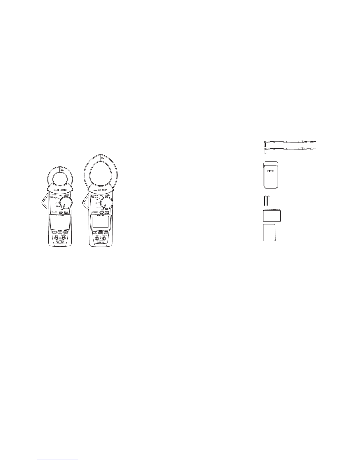
Package contents
AC/DC Clamp Meter
L9207-10 Test lead
L4937 マグネットアダプ
タ
L4934 小ワニグチ
マグネ付ストラップ
C0203 Carrying Case
LR03 Alkaline battery × 2
Instruction Manual*
Precautions Concerning Use of
Equipment That Emits Radio Waves
(only for CM4372, CM4374)
* Instruction manuals may also be available in other languages. Please visit our website at http://www.hioki.com
Registered trademark
• Bluetooth® is a registered trademark of Bluetooth SIG, Inc.(USA). The trademark is used by HIOKI E.E.
CORPORATION under license.
• Android
TM
and Google PlayTM are registered trademarks of Google, Inc.
• IOS is a registered trademark of Cisco in the U.S. and other countries.
• iPhone
®
, iPad®, iPad miniTM, iPad ProTM, and iPod Touch® are registered trademarks of Apple Inc.
• The App Store is a service mark of Apple Inc.
Page 6
3
Options (sold separately)
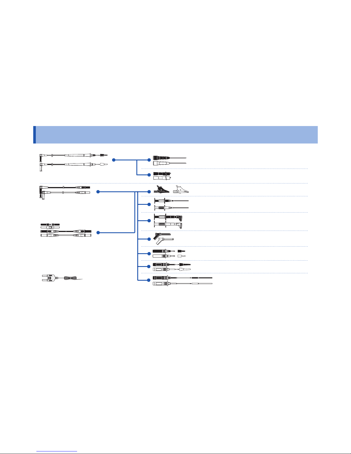
Options (sold separately)
9243 graber
L4937 マグネットアダプ
タ
L4934 小ワニグチ
マグネ付ストラップ
DM4910 熱電対
DT4911TestLead
DT4912TestLead
L4930 接続ケーブル
9243 graber
L4937 マグネットアダプ
タ
L4934 小ワニグチ
マグネ付ストラップ
L9207-10
DM4910 熱電対
DT4911TestLead
DT4912TestLead
L4930 接続ケーブル
L4931renketu
9243 graber
L4937 マグネットアダプ
タ
L4934 小ワニグチ
マグネ付ストラップ
L9207-10
DM4910 熱電対
DT4911TestLead
DT4912TestLead
L4930 接続ケーブル
L4931renketu
L4931 延長ケーブル
L4932(+9207-10cap)
L4933 コンタクトピン
L4935 ワニ口
9243 graber
L4937 マグネットアダプ
9243 graber
L4937 マグネットアダプ
タ
L4934 小ワニグチ
マグネ付ストラップ
L9207-10
DM4910 熱電対
DT4911TestLead
DT4912TestLead
L4930 接続ケーブル
L4931renketu
L4931 延長ケーブル
L4932(+9207-10cap)
L4933 コンタクトピン
L4935 ワニ口
L4936 バスバー
L4937 マグネットアダプ
タ
9243 graber
L4937 マグネットアダプ
タ
L4934 小ワニグチ
マグネ付ストラップ
L9207-10
DM4910 熱電対
DT4911TestLead
DT4912TestLead
L4930 接続ケーブル
L4931renketu
L4931 延長ケーブル
L4932(+9207-10cap)
9243 graber
L4937 マグネットアダプ
タ
L4934 小ワニグチ
マグネ付ストラップ
L9207-10
DM4910 熱電対
DT4911TestLead
DT4912TestLead
L4930 接続ケーブル
L4931renketu
L4931 延長ケーブル
L4932(+9207-10cap)
L4933 コンタクトピン
L4937 マグネットアダプ
タ
L4934 小ワニグチ
L4937 マグネットアダプ
タ
L4934 小ワニグチ
マグネ付ストラップ
L4933 Contact Pin Set
*
6
L4934 Small Alligator Clip Set
*
5
L4935 Alligator Clip Set
*
2
9243 Grabber Clip
*
3
L4936 Bus Bar Clip Set
*
4
L4937 Magnetic Adapter Set
*
3
L4932 Test Pin Set
*
1
L9207-10 Test lead
*
1
L4930 Connection Cable Set
*
2
(Length: 1.2 m)
L4931 Extension Cable Set
*
2
(Length: 1.5 m, with the
coupling connector)
9243 graber
L4937 マグネットアダプ
タ
DM4910 熱電対
DT4910 Thermocouples (K)
L4938 Test Pin Set
*
7
L4939 Breaker Pin Set
*
4
*1: CAT IV 600 V/ CAT III 1000 V/ CAT II 1000 V *4: CAT III 600 V
*2: CAT IV 600 V/ CAT III 1000 V *5: CAT III 300 V/ CAT II 600 V
*3: CAT III 1000 V *6: 33 V AC/ 70 V DC
*7: CAT III 600 V/ CAT II 600 V
Page 7
4
Safety Notes
Safety Notes
This instrument is designed to conform to IEC 61010 Safety Standards, and has been
thoroughly tested for safety prior to shipment. However, using the instrument in a way not
described in this manual may negate the provided safety features.
Before using the instrument, be certain to carefully read the following safety notes.
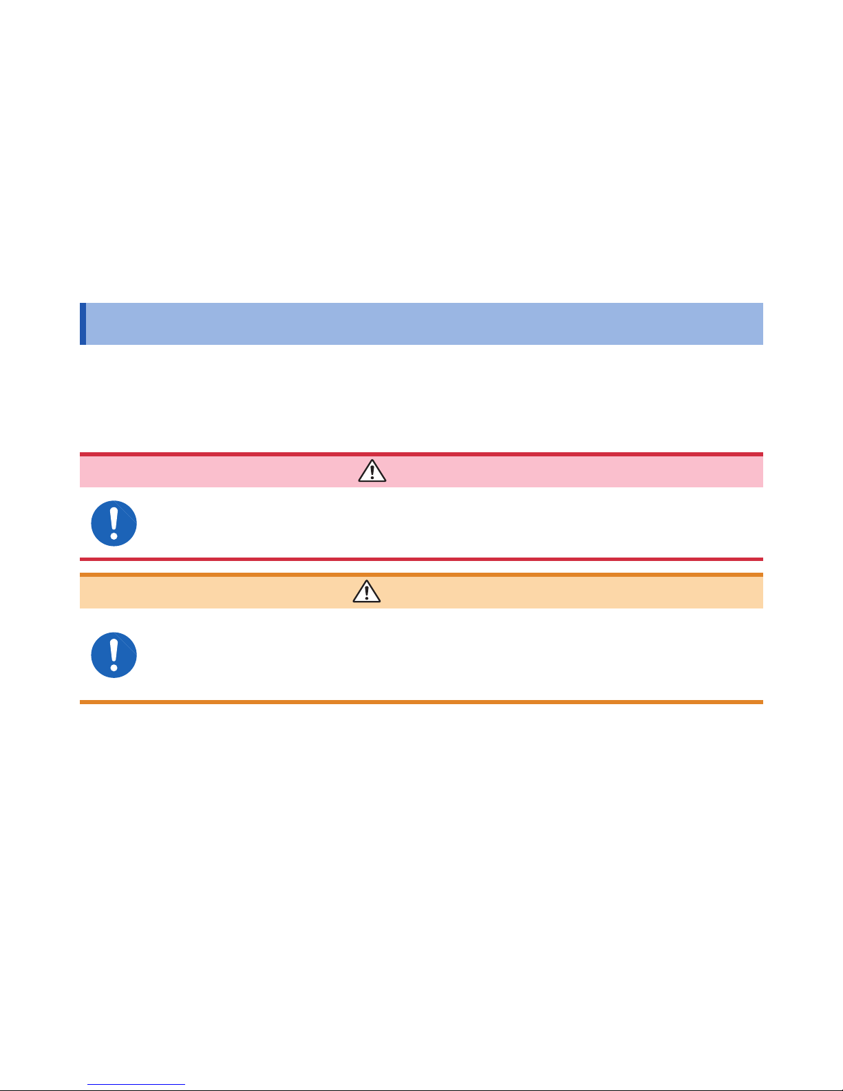
DANGER
Mishandling during use could result in injury or death, as well as damage to the
instrument. Be certain that you understand the instructions and precautions in
the manual before use.
WARNING
With regard to the electricity supply, there are risks of electric shock, heat
generation, re, and arc ash due to short circuits. If persons unfamiliar with
electricity measuring instruments are to use the instrument, another person
familiar with such instruments must supervise operations.
Page 8
5
Safety Notes
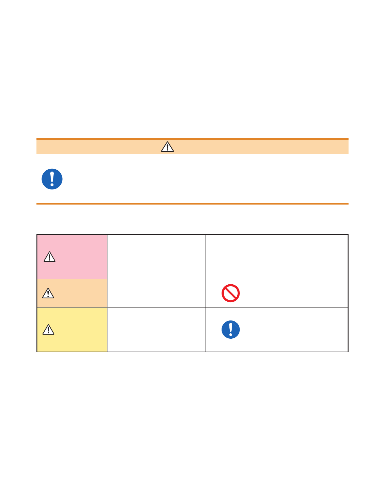
WARNING
Protective gear
This instrument is measured on a live line. To prevent electric shock, use
insulated protective wear such as rubber gloves and rubber boots designed for
electrical work as well as a safety helmet as required by occupational health
and safety regulations.
Notation
In this document, the risk seriousness and the hazard levels are classied as follows.
DANGER
Indicates an imminently
hazardous situation that will
result in death or serious injury
to the operator.
IMPORTANT
Indicates information related to
the operation of the instrument
or maintenance tasks with
which the operators must be
fully familiar.
WARNING
Indicates a potentially hazardous
situation that may result in death
or serious injury to the operator.
Indicates prohibited actions.
CAUTION
Indicates a potentially hazardous
situation that may result in
minor or moderate injury to
the operator or damage to the
instrument or malfunction.
Indicates the action which
must be performed.
Page 9
6
Safety Notes
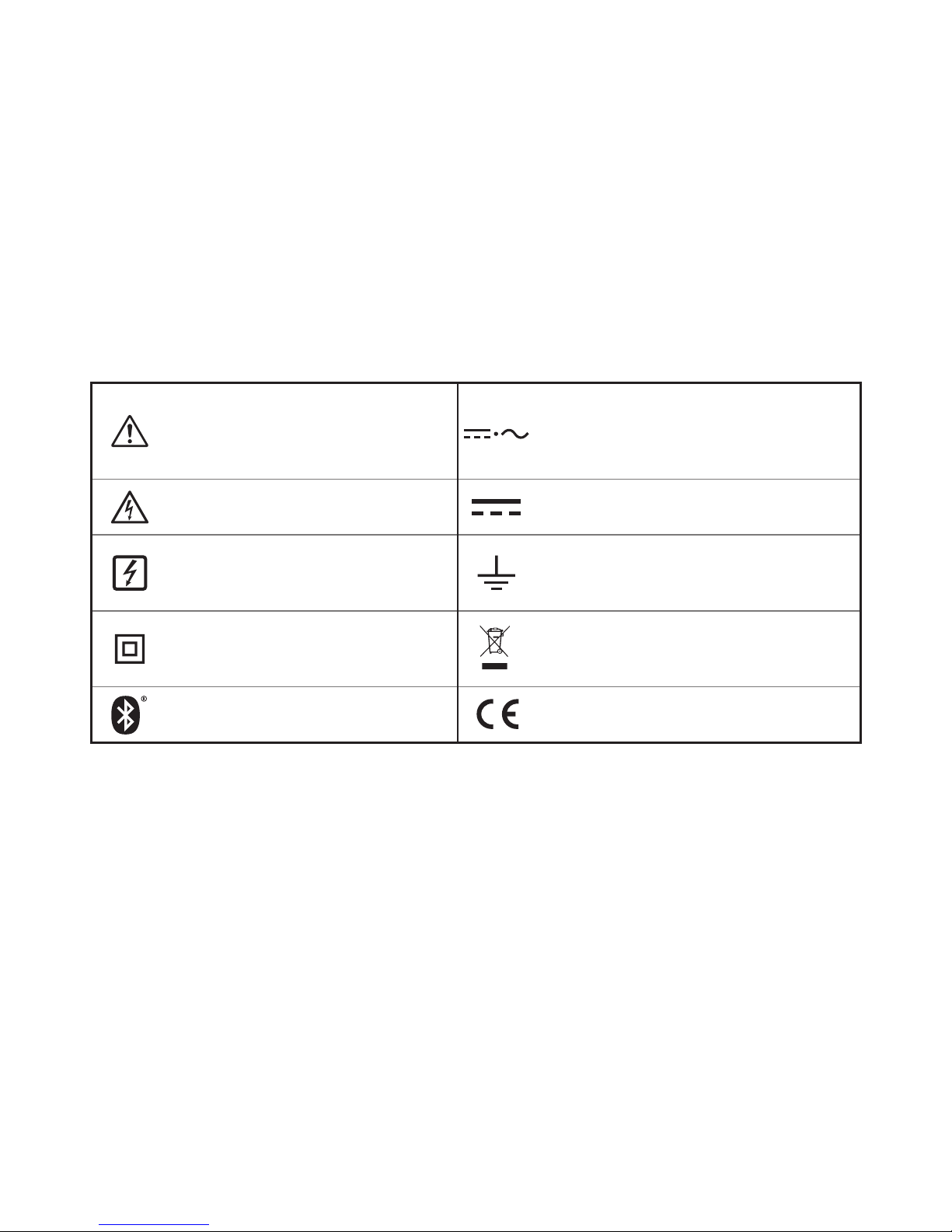
Symbols afxed to the instrument
Indicates cautions and hazards.
When the symbol is printed on the
instrument, refer to a corresponding
topic in the Instruction Manual.
Indicates DC (Direct Current) or AC
(Alternating Current).
Indicates that dangerous voltage may
be present at this terminal.
Indicates DC (Direct Current).
Indicates that the instrument may be
connected to or disconnected from a
live conductor.
Indicates a grounding terminal.
Indicates a instrument that has been
protected throughout by double
insulation or reinforced insulation.
Indicates the Waste Electrical and
Electronic Equipment Directive (WEEE
Directive) in EU member states.
Indicates that the product incorporates
Bluetooth
®
wireless technology.
Indicates that the product conforms to
regulations set out by the EC Directive.
Page 10
7
Safety Notes
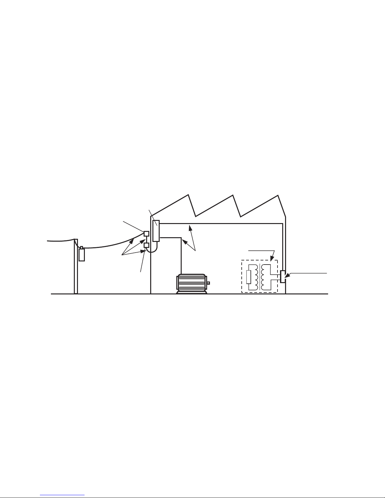
Measurement categories
This instrument conforms to the safety requirements for CAT III 1000 V, CAT IV 600 V
measuring instruments.
T
Outlet
Internal wiring
Distribution panel
Service entrance
Service drop
CAT IV
(≤600 V)
Power meter
CAT III
(≤1000 V)
Fixed installation
CAT II
(≤1000 V)
Page 11
8
Usage Notes
Usage Notes
Follow these precautions to ensure safe operation and to obtain the full benets of the various
functions.
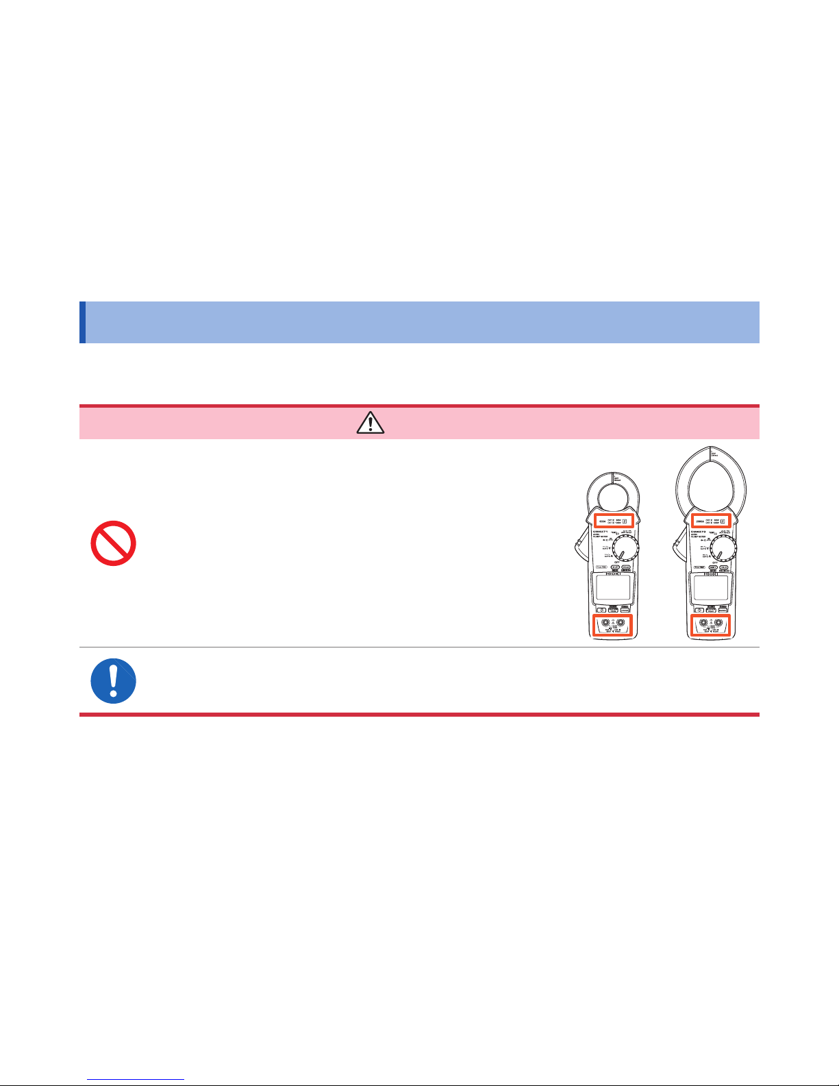
DANGER
Do not input a voltage or current in excess of the
measurement range indicated by the ratings and
specications shown on instrument labeling. Doing
so may damage the instrument or cause it to become
hot, resulting in bodily injury.
To prevent an electric shock, conrm that the white portion (insulation layer)
inside the cable is not exposed. If a color inside the cable is exposed, do not
use the cable.
Page 12
9
Usage Notes
WARNING
Do not allow the instrument to get wet, and do not take measurements with wet
hands. This may cause an electric shock.
To prevent electric shock, when measuring the voltage of a power line use a
test lead that satises the following criteria:
• Conforms to safety standards IEC61010 or EN61010
• Of measurement category III or IV
• Its rated voltage is higher than the voltage to be measured
The optional test leads for this instrument conform to the safety standard
EN61010. Use a test lead in accordance with its dened measurement category
and rated voltage.
CAUTION
Do not drop the instrument or subject it to excessive mechanical shock. Doing so
may damage the surfaces at the tips of the clamp sensor’s jaws, adversely affecting
measurement.
Page 13
10
Usage Notes
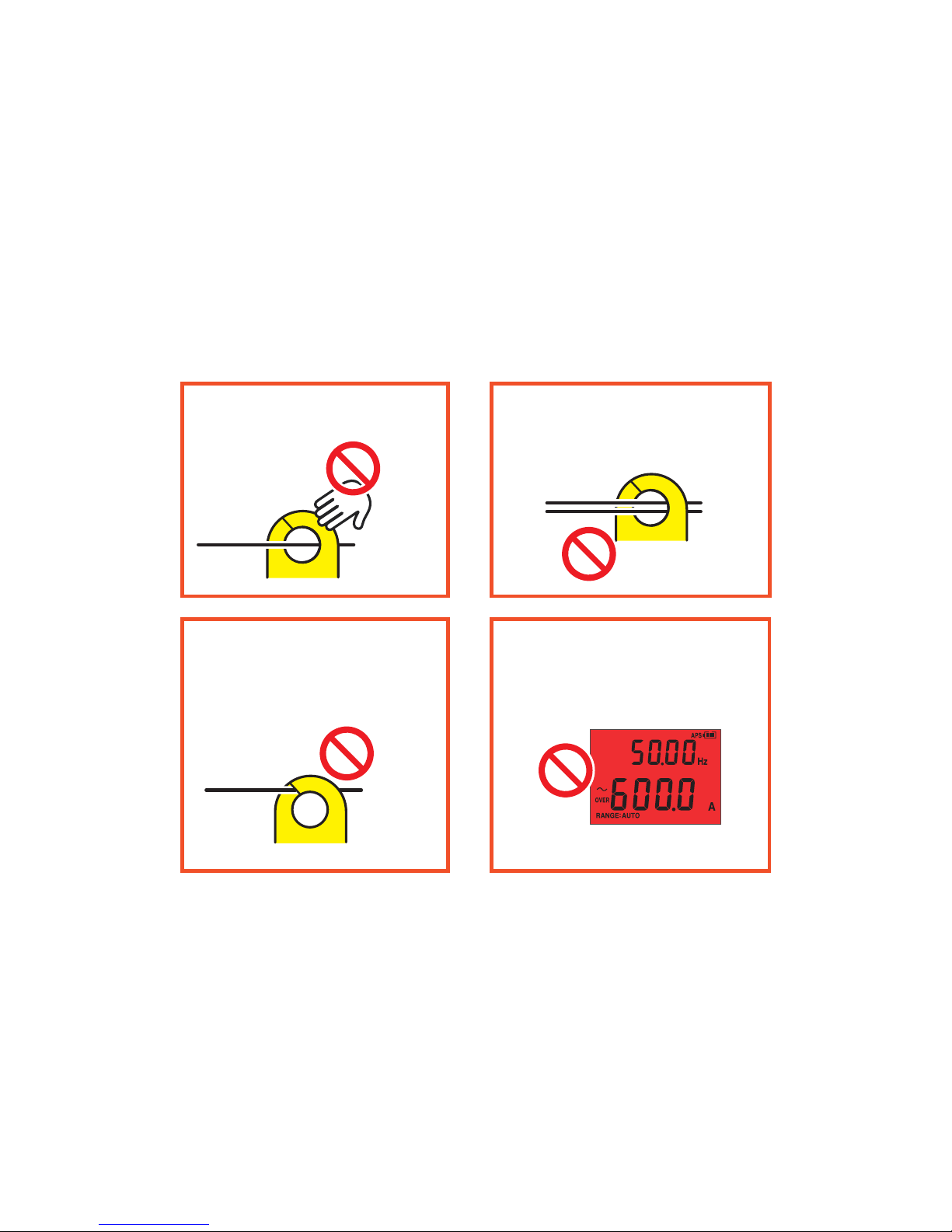
Current measurement precautions
Do not clamp
around two wires.
NO
Do not touch.
Do not pinch wire
between jaws.
NO
Do not input
excessively high
currents.
NO
(Red display)
NO
Page 14
11
Part Names
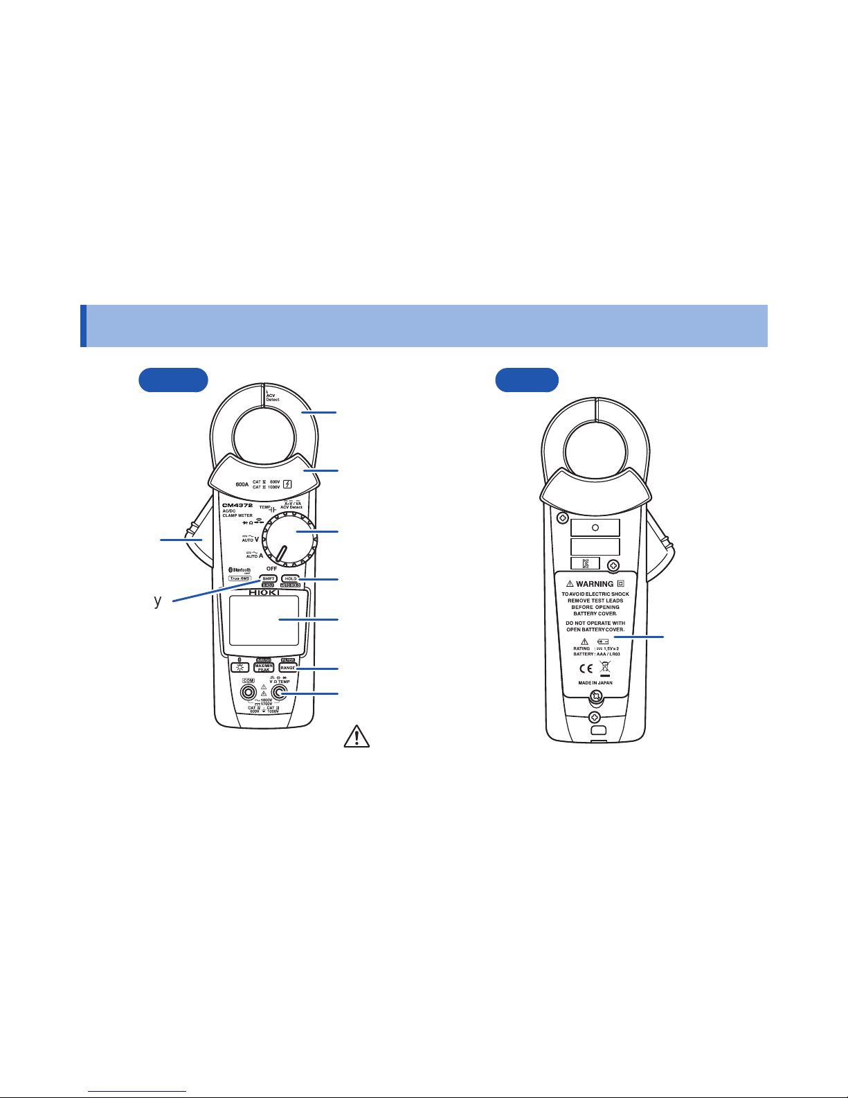
Part Names
Rotary switch
LCD Display
Barrier
HOLD key
Measurement
terminals
SHIFT key
(Selects function
indicated in blue
lettering.)
Operation keys
(p. 8)
Battery cover
Front Rear
(CM4372)
Jaw
(clamp sensor)
Operation
grip
Page 15
12
Insert/Replace Batteries
Insert/Replace Batteries
WARNING
• To prevent electric shock, disconnect test leads before inserting or replacing
the batteries.
• Handle and dispose of batteries in accordance with local regulations.
• To prevent instrument damage or electric shock, use only the screw for
securing the battery cover in place that are originally installed. If you have
lost a screw or nd that a screw is damaged, please contact your Hioki
distributor for a replacement.
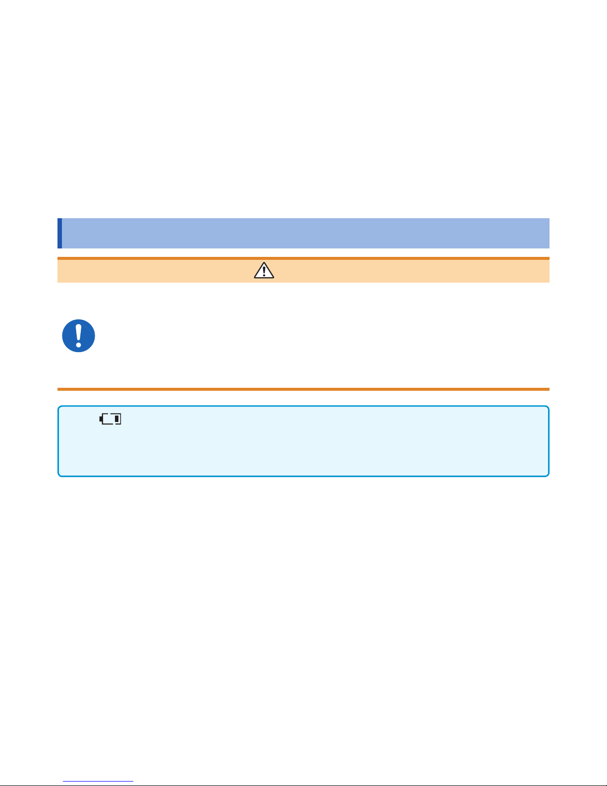
• The
indicator lights up when the battery charge diminishes. Replace the batteries as
soon as possible.
The batteries may die if the backlight turns on or the buzzer sounds.
• After use, be sure to turn off the instrument.
Page 16
13
Insert/Replace Batteries
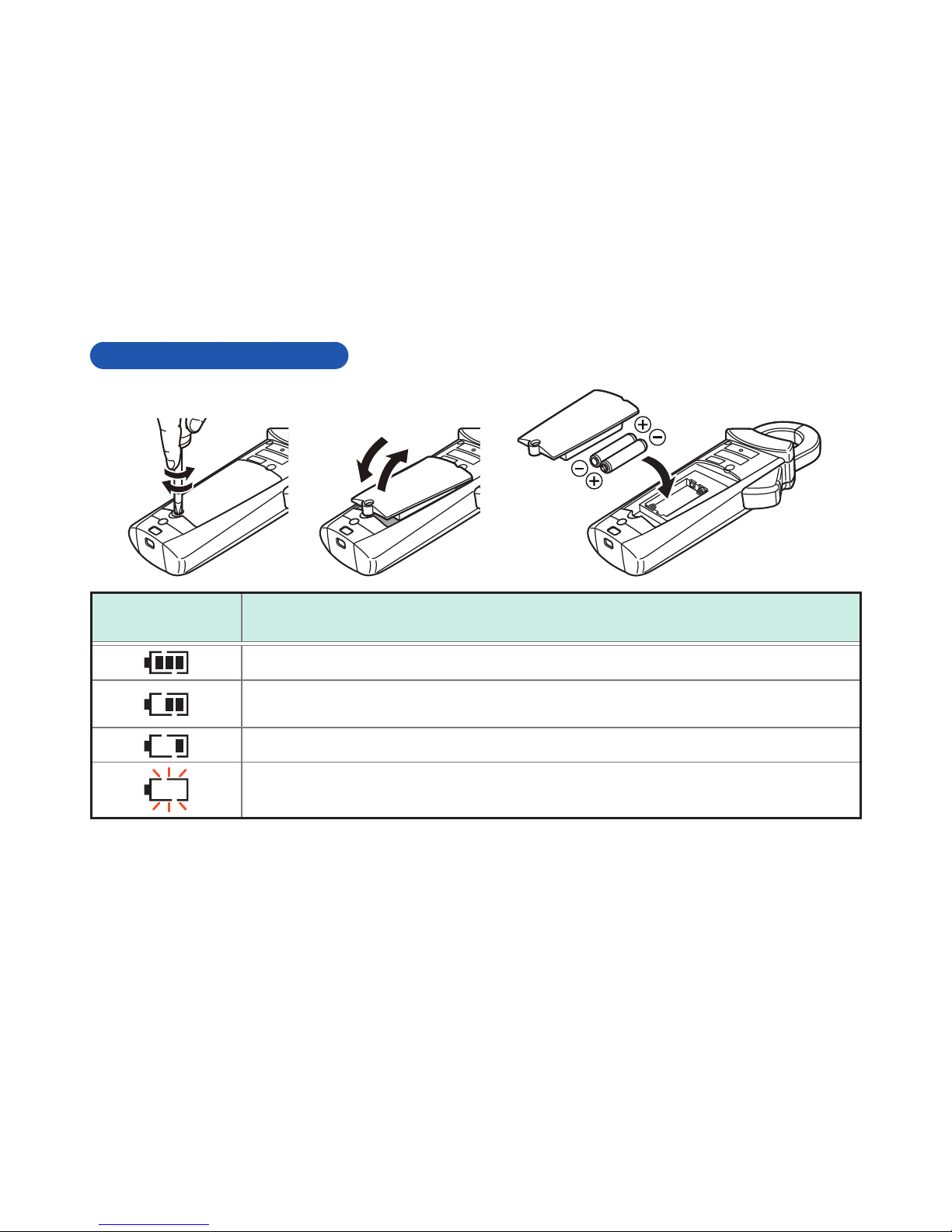
Insert/Replace Batteries
1
2
3
5
4
Battery
indicator
Description
Fully charged.
As the battery charge diminishes, black charge bars disappear, one by one,
from the left of the battery indicator.
The battery voltage is low. Replace the batteries as soon as possible.
(Blinks) The battery is exhausted. Replace the batteries.
Page 17
14
Inspection Before Measurement
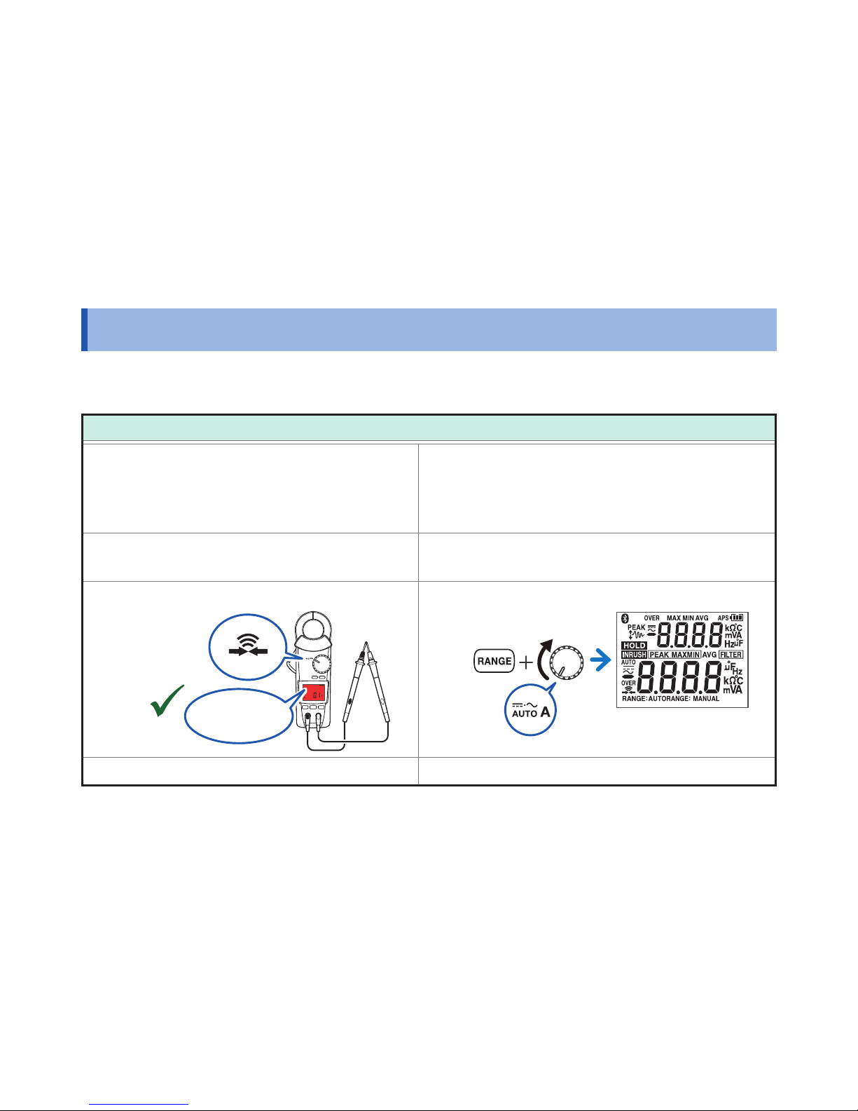
Inspection Before Measurement
Verify that the instrument operates normally to ensure that no damage occured during storage
or shipping. If you nd any damage, contact your authorized Hioki distributor or reseller.
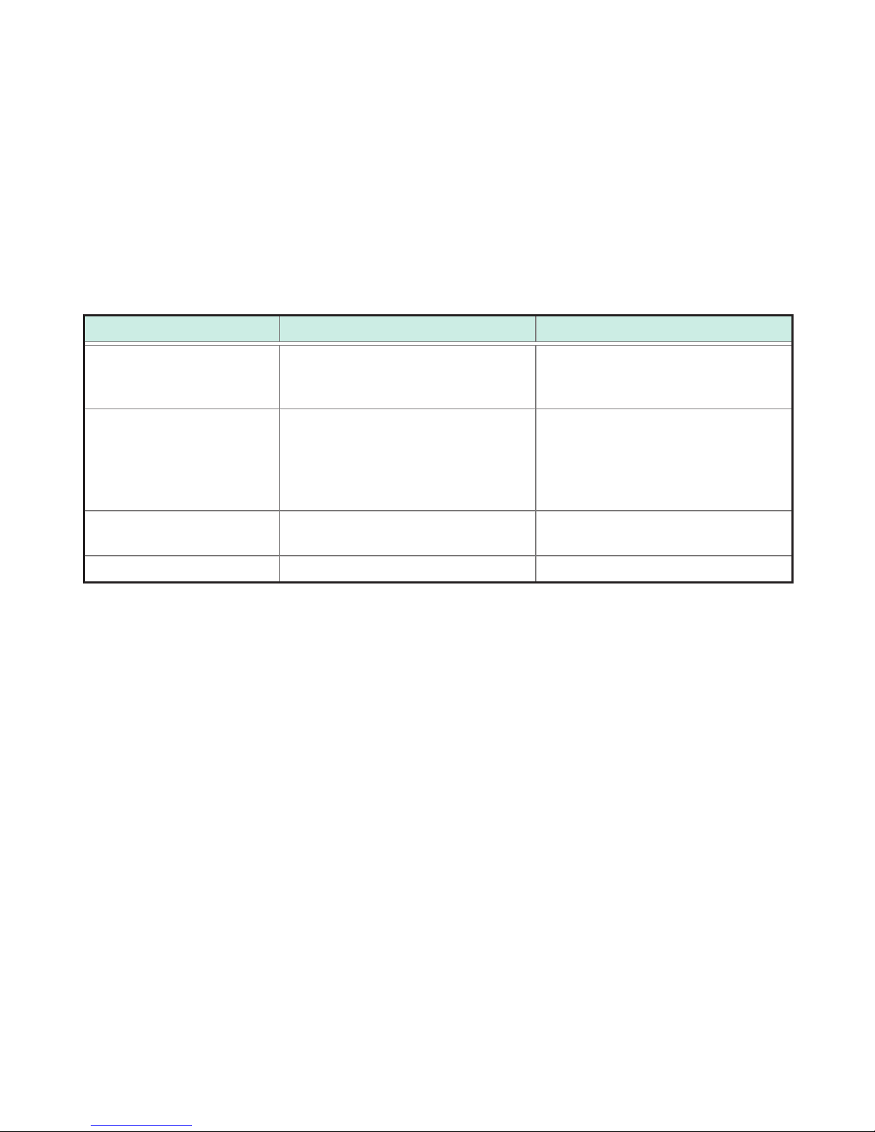
Check item
The battery cover is closed and its screw
has been securely tightened.
There is no damage to the test lead
insulation, and neither the white sheathing
nor metal conductor inside the wire are
exposed.
There is no foreign matter on the
measurement terminals. (p. 11)
The instrument is neither damaged nor
cracked.
The test leads are not broken.
OK
NO
NONO
1 Ω or less
No indicators are missing.
(All lit up)
The battery voltage (p. 13) is sufcient.
Page 18
15
Current Measurement
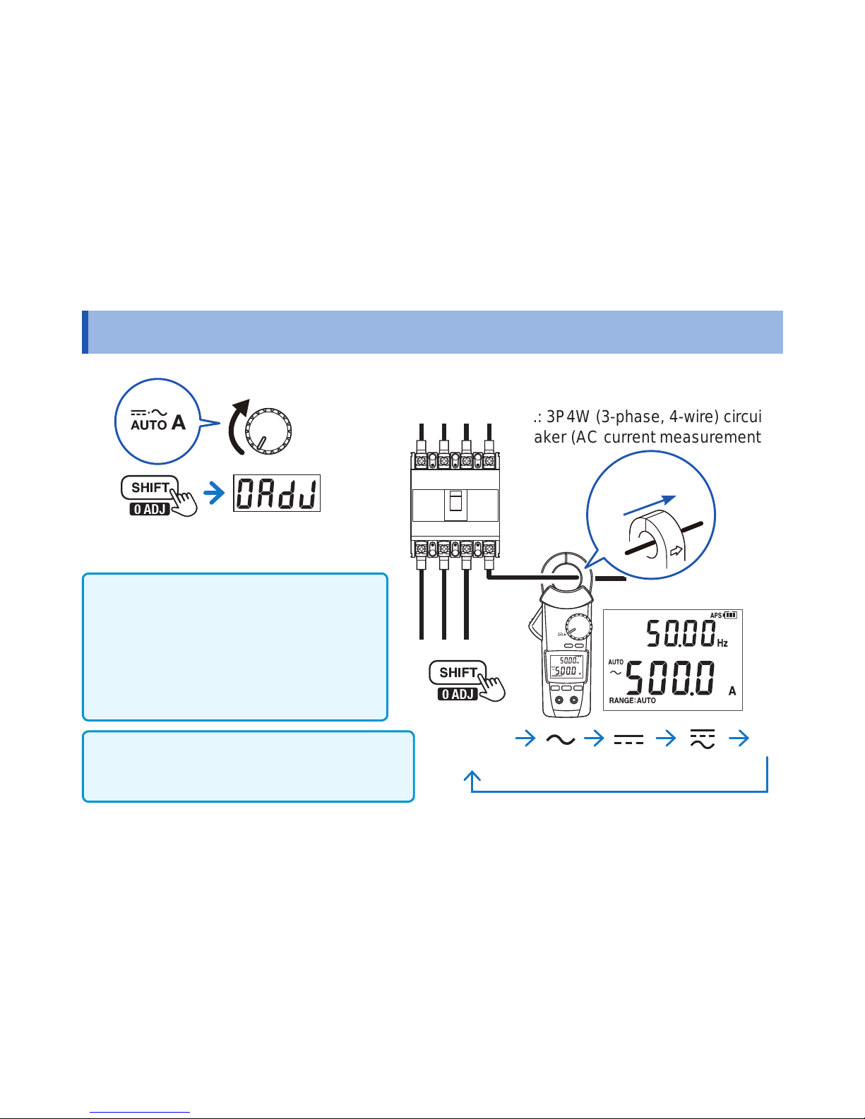
Current Measurement
DC current polarity detection function (p. 34)
If the measured value is negative, the buzzer will
sound, and the display will turn red (threshold: -10 A).
e.g.: 3P4W (3-phase, 4-wire) circuit
breaker (AC current measurement)
4
HzAUTO
(AUTO AC/DC)
(AC+DC A)
(DC A)
(AC A)
3
Clamp the wire.
2
Press for 1 sec.
→Perform zero adjustment
1
Current
direction
Frequency detection range of AC current
CM4371, CM4372:
20.00 A range 4.00 A or more
600.0 A range 20.0 A or more
CM4373, CM4374:
600.0 A range 40.0 A or more
2000 A range 200 A or more
Page 19
16
Manual Hold / Auto Hold
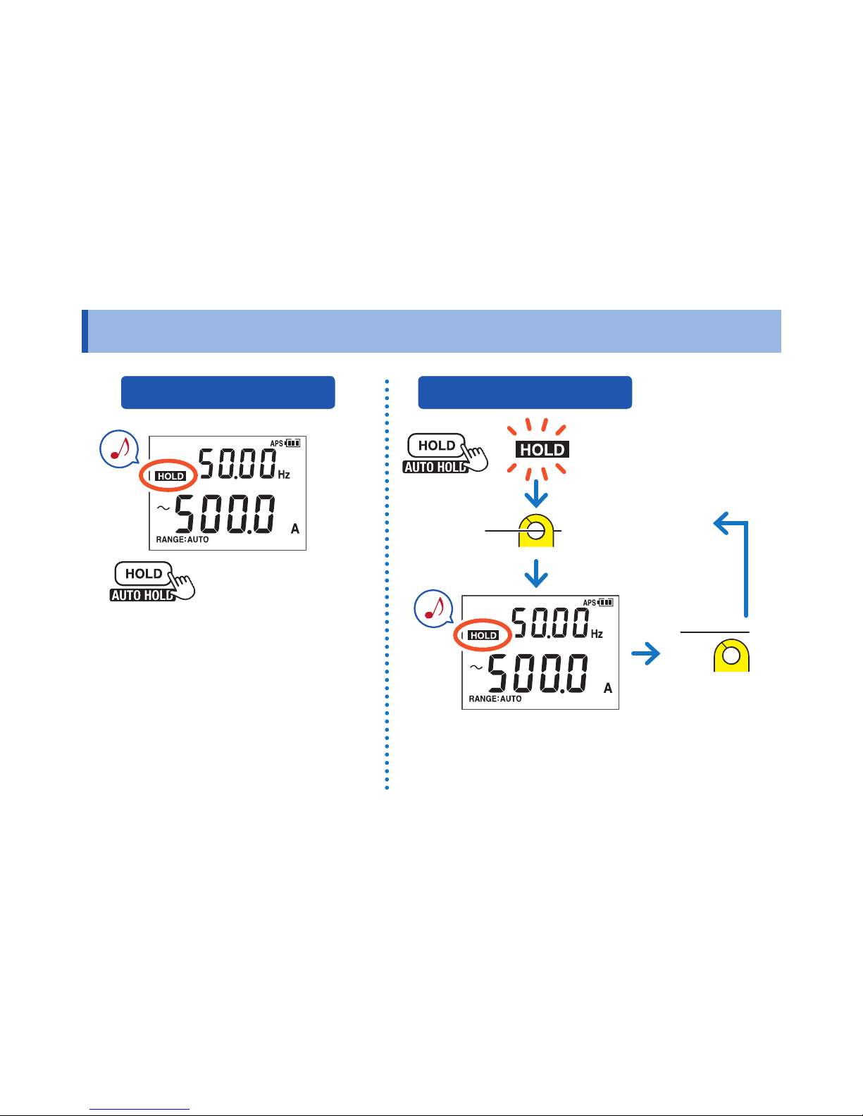
Manual Hold / Auto Hold
→ Measured value retains.
(Measured value stabilizes.)
Measured value automatically retains.
To measured
target
Pressing the HOLD key again cancels
the measured value hold function.
→ blinks.
Pressing the HOLD key for 1 second cancels
the auto hold function.
Press for 1 sec.
Disconnect
MANUAL HOLD AUTO HOLD
Page 20
17
Manual Hold / Auto Hold
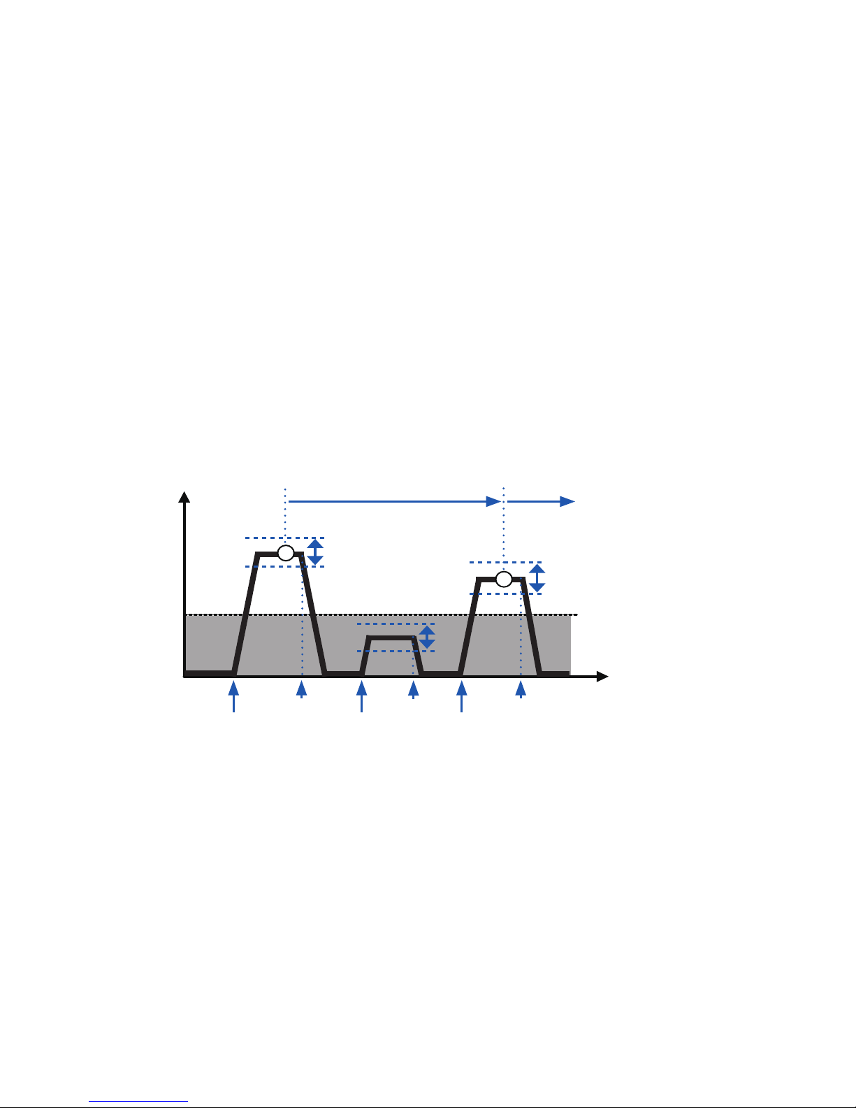
Auto hold conditions
Display value updates are stopped when the following two conditions are satised:
• When the measured value exceeds the threshold value described in the table in the next page.
(voltage, current)
When the measured value is less than the threshold value described in the table in the next page.
(resistance, continuity, diode)
• When the range over which the measured value is uctuating stabilizes within the uctuation range
described in the table in the next page.
Auto hold
e.g.: 100.0 A
Auto hold
e.g.: 99.0 A
Held
measured
value
Measured
value
Start
End
End
End
Fluctuation range
Fluctuation range
Fluctuation
range
Threshold value
e.g.: 12.0 A
Measurement
Start
Start
Time
If the measured value falls below the threshold value (voltage, current) or exceeds the threshold value
(resistance, continuity, diode) after display value updates are stopped, display value updates will stop once
more if the two conditions are satised again.
Page 21
18
Manual Hold / Auto Hold
Measurement function Fluctuation range Threshold value
AC current
DC current
AC+DC current
20.00 A range: within 100 counts
600.0 A range: within 120 counts
2000 A range: within 40 counts
20.00 A range: 100 counts
600.0 A range: 120 counts
2000 A range: 40 counts
AC voltage
DC voltage
(excluding the 600.0 mV
range)
AC+DC voltage
6.000 V/ 60.00 V/ 600.0 V range:
within 120 counts
1000 V range: within 20 counts
1500 V range: within 30 counts
6.000 V/ 60.00 V/ 600.0 V range:
120 counts
1000 V range: 20 counts
1500 V range: within 30 counts
Resistance, Continuity 600.0
Ω
/6.000 kΩ/60.00 kΩ/600.0 kΩ
range: within 100 counts
600.0 Ω/6.000 kΩ/60.00 kΩ/600.0 kΩ
range: 4900 counts
Diode 1.800 V range: within 40 counts 1.800 V range: 1460 counts
The auto hold function only operates for the above measurement functions.
Page 22
19
Switching ranges
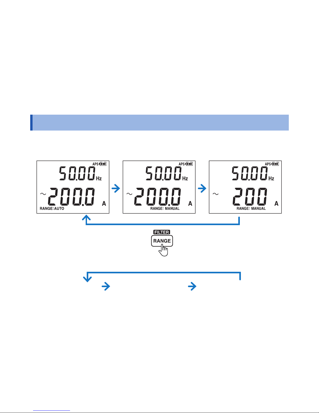
Switching ranges
AUTO range MANUAL 2000 A rangeMANUAL 600.0 A range
AUTO range
MANUAL 600.0 A rangeMANUAL 20.00 A range
e.g. 1: Current measurement with the CM4373, CM4374
e.g. 2: Current measurement with the CM4371, CM4372
Page 23

20
Filter Function
Filter Function
FILTER OFF
Measured value including noise
Press for
1 sec.
Frequency [Hz]
Measurement value [A]
FILTER OFF
FILTER ON Passband 100 [Hz]
Measured value with reduced noise
Frequency characteristics when
using the lter
(600.0 A AC range, 100 A input)
Turn off the lter function when performing
measurement of power supply frequencies
in excess of 100 Hz, for example on an
aircraft or ship.
Filter OFF
FILTER ON
Page 24

21
MAX/MIN/AVG/PEAK
MAX/MIN/AVG/PEAK
Can not be used at
AUTO AC/DC.
1
2
Hz
AUTO
(AUTO AC/DC)
(AC+DC A)
(DC A)(AC A)
3
Press for 1 sec.
→Cancel
PEAK MAX
PEAK MIN
MAX
Display refresh interval
Waveform
Measured value
(RMS value)
MIN
The instrument
performs true RMS
measurement.
→ Measured value retains.
4
Page 25

22
Simultaneous display of DC current/voltage peak values
Simultaneous display of DC current/voltage peak values
Red
Black
1
Press for 1 sec.
→PEAK display ON
2
Press for 1 sec.
→Cancel
4
(p. 28)
PEAK MIN
PEAK MAX
PEAK MIN
PEAK MAX
DC current
DC voltage
3
Engine starts
(PEAK occurrence)
Voltage: 60.00 V range (xed)
Current: 600.0 A range (xed) (CM4371, CM4372)
Trigger level: ±60 A
Current: 2000 A range (xed) (CM4373, CM4374)
Trigger level: ±200 A
Page 26

23
Backlight / Auto Power Save (APS)
Backlight / Auto Power Save (APS)
Backlight
Backlight ON
Power OFF
To restart the instrument, briey set the rotary switch to “OFF.”
Backlight OFF
No operation for 45 min.
You can turn the display back on by
pressing a key or by turning the rotary
switch.
No operation for 15 min.
(Always on)
Cancelation method: p. 34
Auto Power Save (APS)
Page 27

24
Rush current (INRUSH)
Rush current (INRUSH)
600.0 A range (xed) (CM4371, CM4372)
Trigger level: ±10 A
2000 A range (xed) (CM4373, CM4374)
Trigger level: ±100 A
1
MOTOR OFF
6
MOTOR ON
7
Rush current
occurrence
5
Press for 1 sec.
→INRUSH ON
4
Clamp the wire.
3
Press for 1 sec.
→Zero adjustment
2
Maximum wave height (PEAK)
Example screen: 250 A
Interval during which rush
current occurs
(Dozens to hundreds of
milliseconds in duration)
AC current
RMS value (INRUSH)
DC current
Maximum wave height (PEAK)
Example
screen: 100 A
RMS value (INRUSH)
Interval during which rush
current occurs
(Dozens to hundreds of
milliseconds in duration)
Page 28

25
Other Measurement Functions
Other Measurement Functions
DC voltage polarity detection function (p. 34)
If the measured value is negative, the buzzer will
sound, and the display will turn red (threshold: −10 V).
(Red display)
2
3
e.g.: commercial power supply (AC voltage measurement)
Do not touch.
Do not input excessively
high voltage.
NO
Red Black
NO
1
Voltage
Hz
AUTO
(AUTO AC/DC)
(AC+DC V)
(DC V)
(AC V)
Page 29

26
Other Measurement Functions
Continuity Check
2
Black
Red
Black
Red
BlackRed
2
Press for 1 sec.
Zero adjustment
1
Press for 1 sec.
Zero adjustment
1
Resistance Diode
(Red display)
Page 30

27
Other Measurement Functions
Capacitance
DT4910
: when DT4910
is broken.
Red
Black
+
−
Black Red
Temperature
To change the temperature display unit: p. 35
Page 31

28
Other Measurement Functions
e.g.: Checking a car battery
Red
Black
Press for 1 sec.
→PEAK display
(p. 22)
Simultaneous display of
DC current and DC voltage
e.g.: Solar power
system maintenance
DC power
Grip as shown in gure.
Electric Charge
Detection
(Red display)
The current range is xed:
600.0 A range (xed): CM4371, CM4372
2000 A range (xed): CM4373, CM4374
Page 32

29
Bluetooth® Communications (only for CM4372, CM4374)
Bluetooth® Communications (only for CM4372, CM4374)
The CM4372 and CM4374 are clamp-style meters with Bluetooth® Smart (Bluetooth® Low Energy) support.
When the Bluetooth
®
function is enabled, you can review measurement data and create measurement reports
on mobile devices (iPhone
®
, iPad®, iPad Mini™, iPad Pro™, iPod Touch®, and Android™ devices). For more
information about this functionality, see the Help function in the application software GENNECT Cross.
1
Install the GENNECT Cross on your mobile device. (p. 30)
2
Enable the Bluetooth® function on the CM4372 or CM4374. (p. 31)
Press for
1 sec.
3
Launch the GENNECT Cross and pair it with the CM4372 or
CM4374. (p. 32)
4
Select the General Measurement, Logging (Recording), or
Waveform Graph function. (p. 33)
Page 33

30
Bluetooth® Communications (only for CM4372, CM4374)
Installing the application software GENNECT Cross
Search for “GENNECT Cross” on the App Store
®
from your iPhone®, iPad® or other Apple device, or on
Google Play™ from your Android™ device. Then download and install the GENNECT Cross. You will need
an Apple ID to download the app from the App Store
®
, or a Google account to download the app from Google
Play™. For more information about how to register an account, contact the store at which you purchased your
device.
• Because the CM4372 and CM4374 emit radio waves, use in a country or region where they have not
been approved may be subject to nes or other penalties as a violation of applicable laws or regulations.
For more information, see the attached “Precautions Concerning Use of Equipment That Emits Radio
Waves” or go to our website.
• The CM4372 and CM4374 availability is limited to certain countries. For more information, contact your
authorized Hioki distributor or reseller.
• Bluetooth
®
communications range varies greatly with distance from obstructions (walls, metal obstruction,
etc.) as well as distance from the oor or ground. To ensure stable measurement, verify adequate signal
strength.
• Although this app is provided free of charge, downloading or use of the app may incur Internet connection
charges. Such charges are the sole responsibility of the user.
• This app is not guaranteed to operate on all mobile devices.
Page 34

31
Bluetooth® Communications (only for CM4372, CM4374)
Turning on the Bluetooth® function
Bluetooth® function OFF Bluetooth® function ON
icon will ash when the instrument
is connected to a mobile device.
Press for 1 sec.
Page 35

32
Bluetooth® Communications (only for CM4372, CM4374)
Pairing the app with the CM4372 or CM4374
1
2
3
• When the app is launched for the rst time (before being paired with any instrument), the Instrument
Settings screen will be displayed.
• While the mobile device is displaying the Instrument Settings screen, simply move it close to a CM4372 or
CM4374 to automatically pair it with the instrument (the app can be paired with up to 8 instruments).
• Allow about 5 to 30 seconds for the instrument to pair with the app after being turned on. If the instrument
fails to pair within 1 minute, relaunch GENNECT Cross and cycle the instrument’s power.
Page 36

33
Bluetooth® Communications (only for CM4372, CM4374)
Making measurements with the Bluetooth® function
Select the General Measurement, Logging (Recording), or Waveform Graph function on
the Home screen. For more information about each function, see the Help function in the
GENNECT Cross.
General Measurement
Saves measured values from
multiple channels
Logging (Recording)
Simple logging (up to 24 hours)
Waveform Graph
Simple oscilloscope
(voltage/current)
Page 37

34
Power-on Option Table
Power-on Option Table
+
Turn on the power while pressing the operation key.
(Turn the rotary switch from OFF.)
Setting Operating instruction
Factory
setting
Setting
retained?
Canceling the auto power save
(APS) function
ON
No
(Set each time)
DC current and DC voltage
polarity detection function
(ON/OFF)
OFF Yes
Displaying all indicators
(Version of software/Model
number)
− −
Buzzer sound (ON/OFF)
ON Yes
Automatic backlight
deactivation (ON/OFF)
ON Yes
Page 38

35
Power-on Option Table
Setting Operating instruction
Factory
setting
Setting
retained?
Switching the temperature unit
To change the
temperature unit:
Press for 1 sec.
To save the setting:
Press for 1 sec.
°C Yes
Page 39

36
Repairs, Inspections, and Cleaning
Repairs, Inspections, and Cleaning
Cleaning
To clean the instrument, wipe it gently with a soft cloth moistened with water or mild detergent.
Troubleshooting
Symptom Verication and/or Solution
• The instrument is indicating
an abnormal measured
value for current.
• Is the measured current value too small for the instrument’s measurement
range?
Wrap the wire around the clamp sensor one or more times. Each additional
wrap of the wire will increase the measured value, so that wrapping it once
yields a measured value that is twice the actual value and wrapping it
twice yields a measured value that is three times the actual value.
• Are the tips of the clamp sensor’s jaws open?
• Is the clamp sensor damaged?
If the sensor is damaged or cracked, it will not be able to measure current
accurately. Send the instrument for repair.
Page 40

37
Repairs, Inspections, and Cleaning
Symptom Verication and/or Solution
• When readings from the
instrument are compared
with those of another
clamp-on current meter, the
measured values differ.
• The instrument cannot accurately measure waveforms that contain a
component that falls outside the frequency characteristics range.
• Since the instrument performs true RMS measurement, it can accurately
measure distorted waveforms. When measuring a distorted waveform,
the measured value will differ from a clamp-on current meter that uses the
averaging method.
• The current value is larger
than expected.
• A current value is displayed
even though there is no
input.
• The instrument cannot perform measurement accurately in the presence
of a strong magnetic eld from a source such as a nearby transformer
or high-current circuit or in the presence of a strong electric eld from a
source such as a wireless device.
• A sound is being emitted
by the instrument’s clamp
sensor.
• The clamp sensor may emit sound when measuring AC currents in excess
of approx. 500 A, however, there is no effect on the measurement.
• The measured value does
not appear.
• No measured value is
displayed, even when the
test leads are shorted.
• Zero adjustment is
impossible.
• Check the continuity of the test leads. (p. 26)
If a wiring break is found, replace the test leads.
• Insert the test leads all the way.
• Use the proper measurement method.
If no problem can be found, the instrument may be damaged.
Send the instrument for repair.
• When performing current measurement, perform zero-adjustment while no
measurement target is being clamped.
Page 41

38
Repairs, Inspections, and Cleaning
Error display
Error display Description Solution
Err 001
ROM error
Program
When the error appears in the display, it is
necessary to repair the instrument.
Please contact your authorized Hioki
distributor or reseller.
Err 002
ROM error
Adjustment data
Err 005
ADC error
Hardware malfunction
Err 008
Bluetooth® error
Hardware malfunction
(only for
CM4372, CM4374)
Page 42

39
Specications
Specications
General Specications
Dimensions CM4371, CM4372: Approx. 65W × 215H × 35D mm (2.56″W × 8.46″H × 1.38″D)
CM4373, CM4374: Approx. 65W × 250H × 35D mm (2.56″W × 9.84″H × 1.38″D)
(excluding protruding parts, operation grip, and jaw)
Jaw dimensions CM4371, CM4372: Approx. 69W × 14D mm (2.72″W × 0.55″D)
CM4373, CM4374: Approx. 92W × 18D mm (3.62″W × 0.71″D)
Maximum measurable
conductor diameter
CM4371, CM4372:
φ
33 mm
CM4373, CM4374:
φ
55 mm
Mass CM4371, CM4372: Approx. 340 g (12.0 oz.) (excluding batteries)
CM4373, CM4374: Approx. 530 g (18.7 oz.) (excluding batteries)
Product warranty period 3 years
(Measurement accuracy is dened in terms of a 1-year accuracy and a 3-year
accuracy.) (3 years: reference values)
Number of jaw open/close cycles: 30,000
Operating environment Indoors, pollution degree 2, altitude up to 2000 m (6562 ft.)
Operating temperature
and humidity
-25°C to 65°C (-13°F to 149°F), 90% RH or less (no condensation)
Storage temperature and
humidity
-30°C to 70°C (-22°F to 158°F), 90% RH or less (no condensation)
Page 43

40
Specications
Dustproof and waterproof Jaw, barrier: IP50
Grip: IP54 (when measuring an insulated conductor only)
Risk of electric shock from the conductor being measured increases when wet.
Electrical Characteristics
Display update rate
(measured value)
• Measured value excluding electrostatic capacity, frequency, and temperature:
5 times/s (after the range is xed)
• Electrostatic capacity: 0.5 to 5 times/s (The number of times varies depending
on the capacitance.)
• Frequency: 0.3 to 5 times/s (The number of times varies depending on the
capacitance.)
• Temperature: 1 times/s (including thermocouple wiring break check)
(Dened within the measurement range (excluding range changes)).
Maximum terminal-toterminal rated voltage
1000 V AC (up to 1 kHz) /1700 V DC
Maximum rated voltage
to earth
1000 V AC (Measurement category III)
600 V AC (Measurement category IV)
Anticipated transient overvoltage: 8000 V
Rated supply voltage 1.5 V DC ×2
LR03 Alkaline battery ×2
Page 44

41
Specications
Continuous operating
time
• Approx. 45 hours, at 23°C (73.4°F): 10 A AC measurement (CM4371, CM4372),
100 A AC measurement (CM4373, CM4374)
Backlight OFF, Bluetooth OFF
• Approx. 24 hours, at 23°C (73.4°F): 10 A AC measurement (CM4372),
100 A AC measurement (CM4374)
Backlight OFF, Bluetooth ON
Standards
Safety EN61010
EMC EN61326
Specication for Model DT4910 Thermocouples (K)
Sensor type Thermocouples (K)
Tolerance ±2.5°C (Class 2)
Temperature measuring
junction
Exposed type (welding)
Sensor length Approx. 800 mm
Measuring temperature -40°C to 260°C (-40°F to 500°F) (temperature detector)
Operating temperature -15°C to 55°C (5°F to 131°F)
Storage temperature -30°C to 60°C (-22°F to 140°F)
Page 45

42
Specications
CM4372, CM4374 Individual Specications
Bluetooth® Function
Bluetooth® communications
function
Display of measured values on a smartphone or a tablet while using
Bluetooth
®
communications.
External Interface Specications
Interface
Bluetooth
®
4.0LE ( )
Antenna power Maximum +0 dBm (1 mW)
Communications range Approx. 10 m (line of sight)
Communications prole GATT (Generic Attribute Prole)
Supported devices iOS (iPhone
®
5, 3rd iPad®, iPad miniTM, iPad ProTM, 5th iPod Touch® or later)
Android
TM
(Only for or model)
Supported OS iOS 8 or later, Android
TM
4.3 or later
Page 46

43
Specications
Accuracy specications and measurement specications
Guaranteed accuracy period 1 year “Accuracy shown in accuracy table”
3 years (reference values) “Accuracy shown in accuracy table ×1.5”
Guaranteed accuracy period
after adjustment made by Hioki
1 year
Guaranteed accuracy for
temperature and humidity
23°C±5°C (73°F±9°F), 90% RH or less (no condensation)
Temperature characteristic Within the operating temperature range, add “measurement accuracy ×
0.1/°C” (excluding 23°C±5°C (73°F±9°F)).
Other conditions When using the L4931 Extension Cable Set, accuracy is guaranteed for
up to two connected cables (totaling 3 m in length).
AC measurement method True RMS measurement
Conditions of AC accuracy
guarantee
Sine wave input
Page 47

44
Specications
AC current/DC current/AC+DC current common specication
Effects of conductor
position
CM4371, CM4372: within ±1.5% rdg.
CM4373, CM4374: within ±1.0% rdg.
At all positions around the jaw’s center-point reference
Effects of external
magnetic elds
60 Hz AC/DC, with a 400 A/m external magnetic eld
CM4371, CM4372: 2.00 A or less
CM4373, CM4374: 2.0 A or less
Maximum allowable
input (AC/DC)
CM4371, CM4372: 600 A continuous
CM4373, CM4374: 2000 A continuous
Frequency derating characteristics with continuous input (See the graph below)
Input current frequency [Hz]
Maximum allowable input current [A]
Frequency derating characteristics
(CM4371, CM4372)
Input current frequency [Hz]
Maximum allowable input current [A]
Frequency derating characteristics
(CM4373, CM4374)
Page 48

45
Accuracy Table
Accuracy Table
Accuracy
We dene measurement tolerances in terms of f.s. (full scale), rdg. (reading) and dgt. (digit) values with the
following meanings:
f.s.
(maximum display
value/range)
The maximum displayable value.
This is usually the name of the currently selected range.
rdg.
(displayed value)
The value currently being measured and displayed on the measuring instrument.
dgt.
(resolution)
The smallest displayable unit on a digital measuring instrument, i.e., the input value
that causes the digital display to show a “1” as the least-signicant digit.
1
AC current 20.00 A/600.0 A (CM4371, CM4372)
Conditions of guaranteed accuracy: After zero adjustment has been performed
Zero-display range: 5 counts or less
Coupling type: AC coupling
Crest factor: For the 20.00 A range, 7.5
For the 600.0 A range (500.0 A or less), 3
For the 600.0 A range (greater than 500.0 A and less than or equal to
600.0 A), 2.5
Peak detection time width: 1 ms or more (Filter off)
Page 49

46
Accuracy Table
AC current (Measurement value/MAX/MIN/AVG)
Range
(Accuracy guarantee
range)
Resolution
Accuracy
guarantee
frequency range
Measurement accuracy
Filter off Filter on
20.00 A (1.00 A to 20.00 A) 0.01 A 10 Hz≤f<45 Hz ±1.8% rdg.±0.10 A ±2.3% rdg.±0.10 A
45 Hz≤f≤66 Hz ±1.3% rdg.±0.08 A ±1.8% rdg.±0.08 A
66 Hz<f≤1 kHz ±2.0% rdg.±0.10 A -
600.0 A (1.0 A to 600.0 A) 0.1 A 10 Hz≤f<45 Hz ±1.8% rdg.±0.5 A ±2.3% rdg.±0.5 A
45 Hz≤f≤66 Hz ±1.3% rdg.±0.3 A ±1.8% rdg.±0.3 A
66 Hz<f≤1 kHz ±2.0% rdg.±0.5 A -
Auto range movement threshold: 2000 counts or more for upper range, 180 counts or less for lower range.
AC current (PEAK MAX/PEAK MIN)
Range
(Accuracy guarantee
range)
Resolution
Accuracy
guarantee
frequency range
Measurement accuracy
20.00 A (±1.0 A to ±150.0 A) 0.1 A 10 Hz≤f<45 Hz ±1.8% rdg.±0.7 A
45 Hz≤f≤66 Hz ±1.3% rdg.±0.7 A
66 Hz<f≤1 kHz ±2.0% rdg.±0.7 A
600.0 A (±10 A to ±1500 A) 1 A 10 Hz≤f<45 Hz ±1.8% rdg.±7 A
45 Hz≤f≤66 Hz ±1.3% rdg.±7 A
66 Hz<f≤1 kHz ±2.0% rdg.±7 A
Page 50

47
Accuracy Table
2
DC current and auto A DC detection 20.00 A/600.0 A (CM4371, CM4372)
Conditions of guaranteed accuracy: After zero adjustment has been performed
Zero-display range: 5 counts or less
Coupling type: DC coupling
Peak detection time width: 1 ms or more (Filter off)
DC current (Measurement value/MAX/MIN/AVG)
Range
(Accuracy guarantee
range)
Resolution
Measurement accuracy
(Values apply regardless of whether the lter is on or off.)
20.00 A (±1.00 A to ±20.00 A) 0.01 A ±1.3% rdg.±0.08 A
600.0 A (±1.0 A to ±600.0 A) 0.1 A ±1.3% rdg.±0.3 A
Auto range movement threshold: 2000 counts or more for upper range, 180 counts or less for lower range.
DC current (PEAK MAX/PEAK MIN)
Range (Accuracy guarantee range) Resolution Measurement accuracy
20.00 A (±1.0 A to ±150.0 A) 0.1 A ±1.3% rdg.±0.7 A
600.0 A (±10 A to ±1500 A) 1 A ±1.3% rdg.±7 A
Page 51

48
Accuracy Table
3
AC+DC current and auto A AC detection 20.00 A/600.0 A (CM4371, CM4372)
Conditions of guaranteed accuracy: After zero adjustment has been performed
Zero-display range: 5 counts or less
Coupling type: DC coupling
Crest factor: For the 20.00 A range, 7.5
For the 600.0 A range (500.0 A or less), 3
For the 600.0 A range (greater than 500.0 A and less than or equal to
600.0 A), 2.5
Peak detection time width: 1 ms or more (Filter off)
AC+DC current (Measurement value/MAX/MIN/AVG)
Range
(Accuracy guarantee
range)
Resolution
Accuracy guarantee
frequency range
Measurement accuracy
Filter off Filter on
20.00 A (1.00 A to 20.00 A) 0.01 A 10 Hz≤f<45 Hz ±1.8% rdg.±0.10 A ±2.3% rdg.±0.10 A
DC, 45 Hz≤f≤66 Hz ±1.3% rdg.±0.13 A ±1.8% rdg.±0.13 A
66 Hz<f≤1 kHz ±2.0% rdg.±0.10 A -
600.0 A (1.0 A to 600.0 A) 0.1 A 10 Hz≤f<45 Hz ±1.8% rdg.±0.7 A ±2.3% rdg.±0.7 A
DC, 45 Hz≤f≤66 Hz ±1.3% rdg.±1.3 A ±1.8% rdg.±1.3 A
66 Hz<f≤1 kHz ±2.0% rdg.±0.7 A -
Auto range movement threshold: 2000 counts or more for upper range, 180 counts or less for lower range.
Page 52

49
Accuracy Table
AC+DC current (PEAK MAX/PEAK MIN)
Range
(Accuracy
guarantee range)
Resolution
Accuracy guarantee
frequency range
Measurement accuracy
20.00 A (±1.0 A to ±150.0 A) 0.1 A 10 Hz≤f<45 Hz ±1.8% rdg.±0.7 A
DC, 45 Hz≤f≤66 Hz ±1.3% rdg.±0.7 A
66 Hz<f≤1 kHz ±2.0% rdg.±0.7 A
600.0 A (±10 A to ±1500 A) 1 A 10 Hz≤f<45 Hz ±1.8% rdg.±7 A
DC, 45 Hz≤f≤66 Hz ±1.3% rdg.±7 A
66 Hz<f≤1 kHz ±2.0% rdg.±7 A
4
Rush current (INRUSH) 600.0 A (CM4371, CM4372)
Conditions of guaranteed accuracy: After zero adjustment has been performed
INRUSH trigger level: For 600.0 A range, detection of current of +10 A or more or -10 A or less
Coupling type: DC coupling
Crest factor: For the 600.0 A range (500.0 A or less), 3
For the 600.0 A range (greater than 500.0 A and less than or equal to
600.0 A), 2.5
Peak detection time width: 1 ms or more
Page 53

50
Accuracy Table
Rush Current (INRUSH)
Range
(Accuracy
guarantee range)
Resolution
Accuracy guarantee
frequency range
Measurement accuracy
(Values apply regardless of whether the
lter is on or off.)
600.0 A (10.0 A to 600.0 A) 0.1 A DC, 20 Hz≤f≤500 Hz ±5.0% rdg.±1.3 A
Rush Current (INRUSH peak value)
Range
(Accuracy
guarantee range)
Resolution
Accuracy guarantee
frequency range
Measurement accuracy
600.0 A (±10 A to ±1500 A) 1 A DC, 20 Hz≤f≤500 Hz ±6.0% rdg.±10 A
5
AC current 600.0 A/2000 A (CM4373, CM4374)
Conditions of guaranteed accuracy: After zero adjustment has been performed
Zero-display range: 5 counts or less
Coupling type: AC coupling
Crest factor: For the 600.0 A range (500.0 A or less), 3
For the 600.0 A range (greater than 500.0 A and less than or equal to
600.0 A), 2.5
For the 2000 A range (1000 A or less), 2.84
For the 2000 A range (greater than 1000 A and less than or equal to
2000 A), 1.42
Peak detection time width: 1 ms or more (Filter off)
Page 54

51
Accuracy Table
AC current (Measurement value/MAX/MIN/AVG)
Range
(Accuracy
guarantee range)
Resolution
Accuracy guarantee
frequency range
Measurement accuracy
Filter off Filter on
600.0 A (1.0 A to 600.0 A)* 0.1 A 10 Hz≤f<45 Hz ±1.8% rdg.±0.5 A ±2.3% rdg.±0.5 A
45 Hz≤f≤66 Hz ±1.3% rdg.±0.3 A ±1.8% rdg.±0.3 A
66 Hz<f≤1 kHz ±2.0% rdg.±0.5 A -
2000 A (10 A to 1800 A) 1 A 10 Hz≤f<45 Hz ±1.8% rdg.±5 A ±2.3% rdg.±5 A
45 Hz≤f≤66 Hz ±1.3% rdg.±3 A ±1.8% rdg.±3 A
66 Hz<f≤1 kHz ±2.0% rdg.±5 A -
(1801 A to 2000 A) 1 A 10 Hz≤f<45 Hz ±2.8% rdg.±5 A ±3.3% rdg.±5 A
45 Hz≤f≤66 Hz ±2.3% rdg.±3 A ±2.8% rdg.±3 A
66 Hz<f≤1 kHz - -
Auto range movement threshold: 6000 counts or more for upper range, 540 counts or less for lower range.
* For 30.0 A or less, add 0.5 A to the measurement accuracy.
Page 55

52
Accuracy Table
AC current (PEAK MAX/PEAK MIN)
Range
(Accuracy guarantee
range)
Resolution
Accuracy guarantee
frequency range
Measurement accuracy
600.0 A (±10 A to ±1500 A) 1 A 10 Hz≤f<45 Hz ±1.8% rdg.±7 A
45 Hz≤f≤66 Hz ±1.3% rdg.±7 A
66 Hz<f≤1 kHz ±2.0% rdg.±7 A
2000 A (±10 A to ±2300 A) 1 A 10 Hz≤f<45 Hz ±1.8% rdg.±7 A
45 Hz≤f≤66 Hz ±1.3% rdg.±7 A
66 Hz<f≤1 kHz ±2.0% rdg.±7 A
(±2301 A to ±2840 A) 1 A 10 Hz≤f<45 Hz ±6.5% rdg.±7 A
45 Hz≤f≤66 Hz ±6.0% rdg.±7 A
66 Hz<f≤1 kHz -
6
DC current and auto A DC detection 600.0 A/2000 A (CM4373, CM4374)
Conditions of guaranteed accuracy: After zero adjustment has been performed
Zero-display range: 5 counts or less
Coupling type: DC coupling
Peak detection time width: 1 ms or more (Filter off)
Page 56

53
Accuracy Table
DC current (Measurement value/MAX/MIN/AVG)
Range
(Accuracy guarantee
range)
Resolution
Measurement accuracy
(Values apply regardless of whether the lter is on or off.)
600.0 A (±1.0 A to ±600.0 A)* 0.1 A ±1.3% rdg.±0.3 A
2000 A (±10 A to ±2000 A) 1 A ±1.3% rdg.±3 A
Auto range movement threshold: 6000 counts or more for upper range, 540 counts or less for lower range.
* For 30.0 A or less, add 0.5 A to the measurement accuracy.
DC current (PEAK MAX/PEAK MIN)
Range
(Accuracy guarantee
range)
Resolution Measurement accuracy
600.0 A (±10 A to ±1500 A) 1 A ±1.3% rdg.±7 A
2000 A (±10 A to ±2300 A) 1 A ±1.3% rdg.±7 A
(±2301 A to ±2840 A) 1 A ±6.0% rdg.±7 A
Page 57

54
Accuracy Table
7
AC+DC current and auto A AC detection 600.0 A/2000 A (CM4373, CM4374)
Conditions of guaranteed
accuracy: After zero adjustment has been performed
Zero-display range: 5 counts or less
Coupling type: DC coupling
Crest factor: For the 600.0 A range (500.0 A or less), 3
For the 600.0 A range (greater than 500.0 A and less than or equal to 600.0 A), 2.5
For the 2000 A range (1000 A or less), 2.84
For the 2000 A range (greater than 1000 A and less than or equal to 2000 A), 1.42
Peak detection time width: 1 ms or more (Filter off)
AC+DC current (Measurement value/MAX/MIN/AVG)
Range
(Accuracy
guarantee range)
Resolution
Accuracy guarantee
frequency range
Measurement accuracy
Filter off Filter on
600.0 A (1.0 A to 600.0 A) 0.1 A 10 Hz≤f<45 Hz ±1.8% rdg.±0.7 A ±2.3% rdg.±0.7 A
DC, 45 Hz≤f≤66 Hz ±1.3% rdg.±1.3 A ±1.8% rdg.±1.3 A
66 Hz<f≤1 kHz ±2.0% rdg.±0.7 A −
2000 A (10 A to 1800 A) 1 A 10 Hz≤f<45 Hz ±1.8% rdg.±7 A ±2.3% rdg.±7 A
DC, 45 Hz≤f≤66 Hz ±1.3% rdg.±13 A ±1.8% rdg.±13 A
66 Hz<f≤1 kHz ±2.0% rdg.±7 A −
(1801 A to 2000 A) 1 A 10 Hz≤f<45 Hz ±2.8% rdg.±7 A ±3.3% rdg.±7 A
DC, 45 Hz≤f≤66 Hz ±2.3% rdg.±13 A ±2.8% rdg.±13 A
66 Hz<f≤1 kHz − −
Auto range movement threshold: 6000 counts or more for upper range, 540 counts or less for lower range.
Page 58

55
Accuracy Table
AC+DC current (PEAK MAX/PEAK MIN)
Range
(Accuracy guarantee
range)
Resolution
Accuracy guarantee
frequency range
Measurement accuracy
600.0 A (±10 A to ±1500 A) 1 A 10 Hz≤f<45 Hz ±1.8% rdg.±7 A
DC, 45 Hz≤f≤66 Hz ±1.3% rdg.±7 A
66 Hz<f≤1 kHz ±2.0% rdg.±7 A
2000 A (±10 A to ±2300 A) 1 A 10 Hz≤f<45 Hz ±1.8% rdg.±7 A
DC, 45 Hz≤f≤66 Hz ±1.3% rdg.±7 A
66 Hz<f≤1 kHz ±2.0% rdg.±7 A
(±2301 A to ±2840 A) 1 A 10 Hz≤f<45 Hz ±6.5% rdg.±7 A
DC, 45 Hz≤f≤66 Hz ±6.0% rdg.±7 A
66 Hz<f≤1 kHz -
8
Rush Current (INRUSH) 2000 A (CM4373, CM4374)
Conditions of guaranteed accuracy: After zero adjustment has been performed
INRUSH trigger level: For 2000 A range, detection of current of +100 A or more or -100 A or
less
Coupling type: DC coupling
Crest factor: For the 2000 A range (1000 A or less), 2.84
For the 2000 A range (greater than 1000 A and less than or equal to
2000 A), 1.42
Peak detection time width: 1 ms or more
Page 59

56
Accuracy Table
Rush Current (INRUSH) of AC+DC current
Range (Accuracy guarantee range) Resolution
Accuracy guarantee
frequency range
Measurement accuracy
2000 A (100 A to 1800 A) 1 A DC, 20 Hz≤f≤500 Hz ±3.3% rdg.±13 A
(1801 A to 2000 A) 1 A DC, 20 Hz≤f≤66 Hz ±5.0% rdg.±13 A
Rush Current (INRUSH peak value) of AC+DC current
Range (Accuracy guarantee range) Resolution
Accuracy guarantee
frequency range
Measurement accuracy
2000 A (±100 A to ±2300 A) 10 A DC, 20 Hz≤f≤500 Hz ±6.0% rdg.±100 A
(±2310 A to ±2840 A) 10 A DC, 20 Hz≤f≤66 Hz ±8.0% rdg.±100 A
9
AC voltage
CMRR: -60 dB or more (DC, 50 Hz/60 Hz, 1 kΩ unbalance)
Zero-display range: 5 counts or less
Coupling type: AC coupling
Crest factor: For 4000 counts or less, 3
For greater than 4000 counts and less than or equal to 6000 counts, 2
For 850 V or less, 2 (1000 V range only)
For greater than 850 V and less than or equal to 1000 V, 1.7
Peak detection time width: 1 ms or more (Filter off)
Overload protection: Lower of 1870 V DC/1100 V AC or 2×10
7
V • Hz (energized for 1 minute)
Transient overvoltage: 8000 V
Page 60

57
Accuracy Table
AC voltage (Measurement value/MAX/MIN/AVG)
Range
(Accuracy
guarantee
range)
Resolution
Accuracy
guarantee
frequency range*
Measurement accuracy Input
impedance
(at AC 50 Hz)
Filter off Filter on
6.000 V (0.000 V to
0.299 V)
0.001 V 15 Hz≤f<45 Hz ±1.5% rdg.±0.015 V ±2.0% rdg.
±0.015 V
3.2 M
Ω
±5%
45 Hz≤f≤66 Hz ±0.9% rdg.±0.013 V ±1.4% rdg.
±0.013 V
66 Hz<f≤1 kHz ±1.5% rdg.±0.015 V -
6.000 V (0.300 V to
6.000 V)
0.001 V 15 Hz≤f<45 Hz ±1.5% rdg.±0.005 V ±2.0% rdg.
±0.005 V
3.2 M
Ω
±5%
45 Hz≤f≤66 Hz ±0.9% rdg.±0.003 V ±1.4% rdg.
±0.003 V
66 Hz<f≤1 kHz ±1.5% rdg.±0.005 V -
60.00 V (3.00 V to
60.00 V)
0.01 V 15 Hz≤f<45 Hz ±1.5% rdg.±0.05 V ±2.0% rdg.±0.05 V 3.1 M
Ω
±5%
45 Hz≤f≤66 Hz ±0.9% rdg.±0.03 V ±1.4% rdg.±0.03 V
66 Hz<f≤1 kHz ±1.5% rdg.±0.05 V -
600.0 V (30.0 V to
600.0 V)
0.1 V 15 Hz≤f<45 Hz ±1.5% rdg.±0.5 V ±2.0% rdg.±0.5 V 3.0 M
Ω
±5%
45 Hz≤f≤66 Hz ±0.9% rdg.±0.3 V ±1.4% rdg.±0.3 V
66 Hz<f≤1 kHz ±1.5% rdg.±0.5 V -
1000 V (50 V to
1000 V)
1 V 15 Hz≤f<45 Hz ±1.5% rdg.±5 V ±2.0% rdg.±5 V 3.0 M
Ω
±5%
45 Hz≤f≤66 Hz ±0.9% rdg.±3 V ±1.4% rdg.±3 V
66 Hz<f≤1 kHz ±1.5% rdg.±5 V -
Auto range movement threshold: 6000 counts or more for upper range, 540 counts or less for lower range
.
* Frequency range of 15 Hz≤f<20 Hz is designed value.
Within the frequency range of f<45 Hz, the accuracy guarantee assumes a superposed DC voltage of less
than 500 V.
Page 61

58
Accuracy Table
AC voltage (PEAK MAX/PEAK MIN)
Range
(Accuracy guarantee
range)
Resolution
Accuracy guarantee
frequency range*
1
Measurement accuracy
6.000 V (0 V to ±12.00 V) 0.01 V 15 Hz≤f<45 Hz ±1.8% rdg.±0.07 V
45 Hz≤f≤66 Hz ±1.5% rdg.±0.07 V
66 Hz<f≤1 kHz ±1.8% rdg.±0.07 V
60.00 V (±3.0 V to ±120.0 V) 0.1 V 15 Hz≤f<45 Hz ±1.8% rdg.±0.7 V
45 Hz≤f≤66 Hz ±1.5% rdg.±0.7 V
66 Hz<f≤1 kHz ±1.8% rdg.±0.7 V
600.0 V (±30 V to ±1000 V)*
2
1 V 15 Hz≤f<45 Hz ±1.8% rdg.±7 V
45 Hz≤f≤66 Hz ±1.5% rdg.±7 V
66 Hz<f≤1 kHz ±1.8% rdg.±7 V
1000 V (±50 V to ±1000 V)*
3
1 V 15 Hz≤f<45 Hz ±1.8% rdg.±7 V
45 Hz≤f≤66 Hz ±1.5% rdg.±7 V
66 Hz<f≤1 kHz ±1.8% rdg.±7 V
Maximum display count for all ranges: 1200/1700 counts
*1 Frequency range of 15 Hz≤f<20 Hz is designed value.
Within the frequency range of f<45 Hz, the accuracy guarantee assumes a superposed DC voltage of less
than 500 V.
*2 Values of up to ±1200 V are displayed, but accuracy is not dened for display values in excess of 1000 V
(which are provided as reference values).
*3 Values of up to ±1700 V are displayed, but accuracy is not dened for display values in excess of 1000 V
(which are provided as reference values).
Page 62

59
Accuracy Table
10
DC voltage and auto V DC detection
NMRR: -60 dB or more (50 Hz/60 Hz)
CMRR: -100 dB or more (DC, 50 Hz/60 Hz, 1 k
Ω
unbalance)
Coupling type: DC coupling
Peak detection time width: 1 ms or more (Filter off)
Overload protection: Lower of 1870 V DC/1100 V AC or 2×10
7
V • Hz (energized for 1 minute)
DC voltage (Measurement value/MAX/MIN/AVG)
Range (Accuracy guarantee range) Resolution Measurement accuracy
Input impedance
(DC input)
600.0 mV (0.0 mV to ±600.0 mV) 0.1 mV ±0.5% rdg.±0.5 mV 6.7 M
Ω
±5%
6.000 V (0.000 V to ±6.000 V) 0.001 V ±0.5% rdg.±0.003 V 6.7 M
Ω
±5%
60.00 V (0.00 V to ±60.00 V) 0.01 V ±0.5% rdg.±0.03 V 6.1 M
Ω
±5%
600.0 V (0.0 V to ±600.0 V) 0.1 V ±0.5% rdg.±0.3 V 6.0 M
Ω
±5%
1500 V* (0 V to ±1000 V) 1 V ±0.5% rdg.±3 V
6.0 M
Ω
±5%
(±1001 V to ±1700 V) 1 V ±2.0% rdg.±5 V
Auto range movement threshold: 6000 counts or more for upper range, 540 counts or less for lower range.
* In the 1500 V range, the instrument can withstand input of up to 1000 V continuously or input in excess of
1000 V for no greater than 1 minute.
Page 63

60
Accuracy Table
DC voltage (PEAK MAX/PEAK MIN Zero to Peak)
Range (Accuracy guarantee range) Resolution Measurement accuracy
600.0 mV (0 mV to ±1200 mV) 1 mV ±1.0% rdg.±7 mV
6.000 V (0.00 V to ±12.00 V) 0.01 V ±1.0% rdg.±0.07 V
60.00 V (0.0 V to ±120.0 V) 0.1 V ±1.0% rdg.±0.7 V
600.0 V (0 V to ±1000 V) 1 V ±1.0% rdg.±7 V
(±1001 V to ±1200 V) 1 V ±5.0% rdg.±7 V
1500 V (0 V to ±1000 V) 1 V ±1.0% rdg.±7 V
(±1001 V to ±1700 V) 1 V ±5.0% rdg.±7 V
11
AC+DC voltage and auto V AC detection
CMRR: -60 dB or more (DC, 50 Hz/60 Hz, 1 kΩ unbalance)
Zero-display range: 5 counts or less
Coupling type: DC coupling
Crest factor: For 4000 counts or less, 3
For greater than 4000 counts and less than or equal to 6000 counts, 2
For 850 V or less, 2 (1000 V range only)
For greater than 850 V and less than or equal to 1000 V, 1.7
Peak detection time width: 1 ms or more (Filter off)
Overload protection: Lower of 1870 V DC/1100 V AC or 2×10
7
V • Hz (energized for 1 minute)
Transient overvoltage: 8000 V
Page 64

61
Accuracy Table
AC+DC voltage (Measurement value/MAX/MIN/AVG)
Range
(Accuracy
guarantee range)
Resolution
Accuracy
guarantee
frequency range*
Measurement accuracy Input impedance
(DC input,
AC 50 Hz input)
Filter off Filter on
6.000 V
(0.000 V
to 0.299 V)
0.001 V 10 Hz≤f<45 Hz ±1.5% rdg.±0.023 V ±2.0% rdg.±0.023 V DC: 6.7 M
Ω
±5%
AC: 3.2 M
Ω
±5%
DC,
45 Hz≤f≤66 Hz
±1.0% rdg.±0.023 V ±1.5% rdg.±0.023 V
66 Hz<f≤1 kHz ±1.5% rdg.±0.023 V -
6.000 V
(0.300 V
to 6.000 V)
0.001 V 10 Hz≤f<45 Hz ±1.5% rdg.±0.013 V ±2.0% rdg.±0.013 V DC: 6.7 MΩ±5%
AC: 3.2 M
Ω
±5%
DC,
45 Hz≤f≤66 Hz
±1.0% rdg.±0.013 V ±1.5% rdg.±0.013 V
66 Hz<f≤1 kHz ±1.5% rdg.±0.013 V -
60.00 V
(3.00 V to
60.00 V)
0.01 V 10 Hz≤f<45 Hz ±1.5% rdg.±0.13 V ±2.0% rdg.±0.13 V DC: 6.1 MΩ±5%
AC: 3.1 M
Ω
±5%
DC,
45 Hz≤f≤66 Hz
±1.0% rdg.±0.13 V ±1.5% rdg.±0.13 V
66 Hz<f≤1 kHz ±1.5% rdg.±0.13 V -
600.0 V
(30.0 V to
600.0 V)
0.1 V 10 Hz≤f<45 Hz ±1.5% rdg.±0.7 V ±2.0% rdg.±0.7 V DC: 6.0 MΩ±5%
AC: 3.0 M
Ω
±5%
DC,
45 Hz≤f≤66 Hz
±1.0% rdg.±0.7 V ±1.5% rdg.±0.7 V
66 Hz<f≤1 kHz ±1.5% rdg.±0.7 V -
1000 V
(50 V to
1000 V)
1 V 10 Hz≤f<45 Hz ±1.5% rdg.±7 V ±2.0% rdg.±7 V DC: 6.0 MΩ±5%
AC: 3.0 M
Ω
±5%
DC,
45 Hz≤f≤66 Hz
±1.0% rdg.±7 V ±1.5% rdg.±7 V
66 Hz<f≤1 kHz ±1.5% rdg.±7 V -
Auto range movement threshold: 6000 counts or more for upper range, 540 counts or less for lower range.
* Frequency range of 10 Hz≤f<20 Hz is designed value.
Page 65

62
Accuracy Table
AC+DC voltage (PEAK MAX/PEAK MIN)
Range
(Accuracy guarantee
range)
Resolution
Accuracy guarantee
frequency range*
1
Measurement accuracy
6.000 V (0.00 V to ±12.00 V) 0.01 V 10 Hz≤f<45 Hz ±1.5% rdg.±0.07 V
DC, 45 Hz≤f≤66 Hz ±1.0% rdg.±0.07 V
66 Hz<f≤1 kHz ±1.5% rdg.±0.07 V
60.00 V (±3.0 V to ±120.0 V) 0.1 V 10 Hz≤f<45 Hz ±1.5% rdg.±0.7 V
DC, 45 Hz≤f≤66 Hz ±1.0% rdg.±0.7 V
66 Hz<f≤1 kHz ±1.5% rdg.±0.7 V
600.0 V*
2
(±30 V to ±1000 V) 1 V 10 Hz≤f<45 Hz ±1.5% rdg.±7 V
DC, 45 Hz≤f≤66 Hz ±1.0% rdg.±7 V
66 Hz<f≤1 kHz ±1.5% rdg.±7 V
1000 V*
3
(±50 V to ±1000 V) 1 V 10 Hz≤f<45 Hz ±1.5% rdg.±7 V
DC, 45 Hz≤f≤66 Hz ±1.0% rdg.±7 V
66 Hz<f≤1 kHz ±1.5% rdg.±7 V
*1 Frequency range of 10 Hz≤f<20 Hz is designed value.
*2 Values of up to ±1200 V are displayed, but accuracy is not dened for display values in excess of 1000 V
(which are provided as reference values).
*3 Values of up to ±1700 V are displayed, but accuracy is not dened for display values in excess of 1000 V
(which are provided as reference values).
Page 66

63
Accuracy Table
12
Frequency (same for all models)
Frequency is displayed at the same time as the AC current/AC voltage (the frequency is shown on the subdisplay when performing ACA/ACV detection with the auto A/auto V function or when using the ACA/ACV
function, and on the main display when using the Hz function).
Only auto-range operation is available when performing frequency measurement using the ACA/ACV function
(the RANGE key is used to switch the current/voltage range).
Minimum detectable current/voltage:
AC voltage 10% of each range’s f.s. value
AC current 20.00 A range 4.00 A or more (CM4371, CM4372)
600.0 A range 20.0 A or more (CM4371, CM4372)
600.0 A range 40.0 A or more (CM4373, CM4374)
2000 A range 200 A or more (CM4373, CM4374)
In the following circumstances, the instrument will display [----Hz] as the value is outside the measurement
range:
• Less than 1 Hz.
• If the AC current or AC voltage is less than the minimum detectable current or voltage or outside the input
range.
• If there is a superposed DC component when performing ACA/ACV detection with the auto A/auto V
function.
Page 67

64
Accuracy Table
Frequency (Measurement value/MAX/MIN/AVG)
Range (Accuracy guarantee range) Resolution Measurement accuracy
9.999 Hz (1.000 Hz to 9.999 Hz) 0.001 Hz ±0.1% rdg.±0.003 Hz
99.99 Hz (1.00 Hz to 99.99 Hz) 0.01 Hz ±0.1% rdg.±0.01 Hz
999.9 Hz (1.0 Hz to 999.9 Hz) 0.1 Hz ±0.1% rdg.±0.1 Hz
Auto range movement threshold: 9999 counts or more for upper range, 900 counts or less for lower range.
13
Continuity check (same for all models)
Continuity on threshold: 25 Ω±10 Ω (continuous buzzer sound, red warning backlight lights up)
Continuity off threshold: 245
Ω
±10
Ω
Conditions of guaranteed accuracy: After zero adjustment has been performed
Response time: Detection of open or short for 0.5 ms or more
Overload protection: Lower of 1700 V/1000 V AC or 2×10
7
V • Hz (energized for 1 minute)
Overload current: 30 mA or less at steady state, 1.5 A or less at transient state
Range
(Accuracy
guarantee range)
Resolution
Measurement
current
Measurement
accuracy
Open terminal
voltage
600.0
Ω
(0.0 Ω to 600.0 Ω) 0.1
Ω
200 µA±20% ±0.7% rdg.±0.5
Ω
2.0 V DC or less
Page 68

65
Accuracy Table
14
Resistance measurement (same for all models)
Maximum capacity load: 10 mF
Maximum inductive load: 10 H
Conditions of guaranteed accuracy: After zero adjustment has been performed
Overload protection: Lower of 1700 V DC/1000 V AC or 2×10
7
V • Hz (energized for 1 minute)
Overload current: 30 mA or less at steady state, 1.5 A or less at transient state
Resistance measurement (Measurement value/MAX/MIN/AVG)
Range
(Accuracy guarantee
range)
Resolution
Measurement
current
Measurement accuracy
Open terminal
voltage
600.0
Ω
(0.0 Ω to 600.0 Ω) 0.1
Ω
200 µA±20% ±0.7% rdg.±0.5
Ω
2.0 V DC or
less
6.000 k
Ω
(0.000 kΩ to 6.000 kΩ) 0.001 k
Ω
100 µA±20% ±0.7% rdg.±0.005 k
Ω
2.0 V DC or
less
60.00 k
Ω
(0.00 kΩ to 60.00 kΩ) 0.01 k
Ω
10 µA±20% ±0.7% rdg.±0.05 k
Ω
2.0 V DC or
less
600.0 k
Ω
(0.0 kΩ to 600.0 kΩ) 0.1 k
Ω
1 µA±20% ±0.7% rdg.±0.5 k
Ω
2.0 V DC or
less
Auto range movement threshold: 6000 counts or more for upper range, 540 counts or less for lower range.
Page 69

66
Accuracy Table
15
Diode (same for all models)
Overload protection: Lower of 1700 V DC/1000 V AC or 2×10⁷ V • Hz (energized for 1 minute)
Overload current: 30 mA or less at steady state, 1.5 A or less at transient state
Range
(Accuracy guarantee
range)
Resolution Short-circuit current
Measurement
accuracy
Open terminal
voltage
1.800 V (0.000 V to 1.800 V) 0.001 V 200 µA±20% ±0.7% rdg.±0.005 V 2.0 V DC or less
Beeping buzzer tone at forward connection (0.15 V to 1.8 V).
Continuous buzzer tone and red backlight lights up if less than 0.15 V.
16
Electrostatic capacity (same for all models)
Overload protection: Lower of 1700 V DC/1000 V AC or 2×10⁷ V • Hz (energized for 1 minute)
Overload current: 30 mA or less at steady state, 1.5 A or less at transient state
Page 70

67
Accuracy Table
Electrostatic capacity (Measurement value/MAX/MIN/AVG)
Range
(Accuracy guarantee
range)
Resolution Discharge current
Measurement
accuracy
Open
terminal
voltage
1.000 µF (0.000 µF to 1.100 µF) 0.001 µF 10 n/100 n/1 µA±20% ±1.9% rdg.±0.005 µF 2.0 V DC
or less
10.00 µF (0.00 µF to 11.00 µF) 0.01 µF 100 n/1 µ/10 µA±20% ±1.9% rdg.±0.05 µF 2.0 V DC
or less
100.0 µF (0.0 µF to 110.0 µF) 0.1 µF 1 µ/10 µ/100 µA±20% ±1.9% rdg.±0.5 µF 2.0 V DC
or less
1000 µF (0 µF to 1100 µF) 1 µF
10 µ/100 µ/200 µA±20%
±1.9% rdg.±5 µF 2.0 V DC
or less
Auto range movement threshold: 1100 counts or more for upper range, 100 counts or less for lower range.
17
Temperature (same for all models)
Thermocouple: Use the DT4910 Thermocouples (K).
Accuracy gures do not include the DT4910 Thermocouples (K)
error component. [DT4910 error: ±2.5°C (Class 2)]
Instrument reference contact temperature
correction stabilization time:
120 minutes (when ambient temperature is varied abruptly from
60°C to 23°C)
Overload protection: Lower of 1700 V DC/1000 V AC or 2×10
7
V • Hz (energized for 1
minute)
Overload current: 30 mA or less at steady state, 1.5 A or less at transient state
Page 71

68
Accuracy Table
Temperature (Measurement value/MAX/MIN/AVG)
Thermocouple type Range Resolution Accuracy*
1
K
-40.0°C to 400.0°C 0.1°C ±0.5% rdg.±3.0°C
-40°F to 752°F*
2
0.1°F ±0.5% rdg.±5.4°F
*1: In an environment where the temperature of the instrument is ±1°C and stable, the accuracy is specied.
*2: Instrument can be made to display readings in Fahrenheit (°F) by means of special operation.
18
Electric charge detection
During voltage detection, a continuous buzzer sounds and the red warning backlight lights up.
Range (detection sensitivity) Detection voltage range* Detection target frequency
Hi 40 V AC to 600 V AC 50 Hz/60 Hz
Lo 80 V AC to 600 V AC 50 Hz/60 Hz
* In contact with the insulated wire that is equivalent to IV2 mm
2
.
Page 72

69
Accuracy Table
19
DC power 600.0 A (CM4371, CM4372)
Displays the product of DC current and DC voltage.
Accuracy guarantee conditions, zero-display range, connection method, and band depend on the DC current
and DC voltage.
Display range switching* Minimum resolution Measurement accuracy
0.0 VA to 1020 kVA 0.1 VA ±2.0% rdg.±20 dgt.
* Switches the display range automatically based on the voltage range.
20
DC power 2000 A (CM4373, CM4374)
Displays the product of DC current and DC voltage.
Accuracy guarantee conditions, zero-display range, connection method, and band depend on the DC current
and DC voltage.
Display range switching* Minimum resolution Measurement accuracy
0.000 kVA to 3400 kVA 1 VA ±2.0% rdg.±20 dgt.
* Switches the display range automatically based on the voltage range.
 Loading...