

Page 1
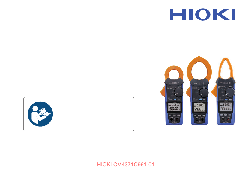
CM4371-50
HIOKI CM4371C961-01
CM4373-50
CM4375-50
AC/DC CLAMP METER
Read carefully before use.
Keep for future reference.
Instruction Manual
EN
Mar. 2023 Revised edition 1
CM4371C961-01
[600625631]
Page 2

Contents
HIOKI CM4371C961-01
Introduction .................................................................................................................1
Notations .....................................................................................................................3
Checking Package Contents .....................................................................................7
Options ........................................................................................................................8
Safety Information ....................................................................................................11
Operating Precautions .............................................................................................12
1 Overview 19
1.1 Product Overview and Features ..........................................................19
1.2 Part Names ............................................................................................20
2 Making Measurements 21
2.1 Inspection Before Measurement ..........................................................21
2.2 Installing Batteries and the Z3210 Wireless Adapter .........................22
Installation procedure ............................................................................................25
2.3 Use of Test Leads ..................................................................................27
L9300 Test Lead (accessory) .................................................................................29
CM4371C961-01
i
Page 3

Contents
HIOKI CM4371C961-01
2.4 Current Measurement ...........................................................................32
2.5 Various Other Measurement Functions ..............................................42
2.6 LCD Backlight, Automatic Power Save (APS) ....................................46
2.7 DC High V Probe Mode .........................................................................47
2.8 Wireless communications function .....................................................51
2.9 Rotary Switch Combinations ...............................................................59
3 Specications 61
3.1 GeneralSpecications .........................................................................61
3.2 InputSpecications,MeasurementSpecications ...........................65
3.3 Accuracy table .......................................................................................75
ii
Manual hold, automatic hold ..................................................................................34
Switching the ranges .............................................................................................38
Filter function .........................................................................................................39
Maximum value, minimum value, average, and peak value ..................................40
Inrush current (inrush) ...........................................................................................41
Using GENNECT Cross .........................................................................................51
Z3210-to-Excel® direct data entry function
(Excel® direct input function, HID function) ............................................................55
Page 4
4 Maintenance and Service 107
HIOKI CM4371C961-01
4.1 Troubleshooting ..................................................................................107
4.2 Error and Operation Displays ............................................................109
4.3 Cleaning ...............................................................................................110
5 Appendix 111
5.1 Voltage Detection Function ................................................................ 111
5.2 Example of Use ...................................................................................113
Index 115
WarrantyCerticate 119
Contents
iii
Page 5

Contents
HIOKI CM4371C961-01
iv
Page 6
Introduction
HIOKI CM4371C961-01
Thank you for choosing the Hioki CM4371-50/CM4373-50/CM4375-50 AC/DC Clamp Meter.
To ensure your ability to get the most out of this instrument over the long term, please read this
manual carefully and keep it available for future reference.
Read the separate document “Operating Precautions” carefully before using the instrument.
Latest edition of instruction manual
The contents of this manual are subject to change, for example as a result of
product improvements or changes to specications.
The latest edition as well as multilingual editions of the manual (in Chinese,
French, German, Italian Korean, and Spanish) can be downloaded from
Hioki’s website.
https://www.hioki.com/global/support/download
Product registration
Register your product in order to receive important product information.
https://www.hioki.com/global/support/myhioki/registration
Introduction
1
Page 7

Introduction
HIOKI CM4371C961-01
Target audience
This manual has been written for use by individuals who use the product in question or who
teach others to do so. It is assumed that the reader possesses basic electrical knowledge
(equivalent to that of someone who graduated from the electrical program at a technical high
school).
Trademarks
• Microsoft Excel is a registered trademark or a trademark of Microsoft Corporation in the
United States and other countries.
• The Bluetooth
and any use of such marks by Hioki E.E. Corporation is under license. Other trademarks and
trade names are those of their respective owners.
2
®
word mark and logos are registered trademarks owned by Bluetooth SIG, Inc.
Page 8
Notations
HIOKI CM4371C961-01
Safety notations
In this document, the severity levels of risk and hazard are classied as follows.
DANGER
WARNING
CAUTION
IMPORTANT
Indicates an imminently
hazardous situation that, if not
avoided, will result in death or
serious injury.
Indicates a potentially hazardous
situation that, if not avoided, could
result in death or serious injury.
Indicates a potentially hazardous
situation that, if not avoided, could
result in minor or moderate injury
or potential risks of damage to
the supported product (or to other
property).
Indicates information or content
that is particularly important from
the stand point of operating or
maintaining the instrument.
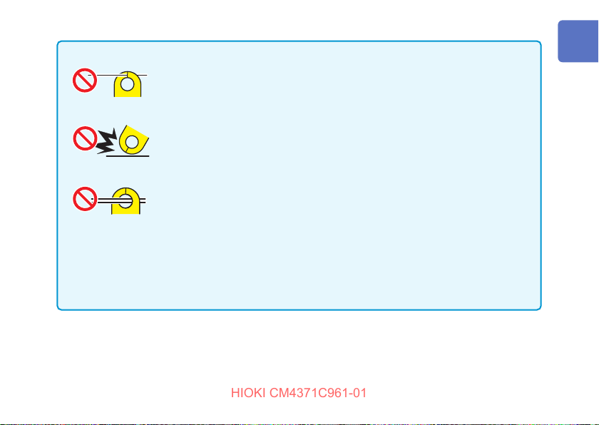
Notations
Indicates an action that must not
be performed.
Indicates an action that must be
performed.
Indicates a high-voltage hazard.
Failure to verify safety or improper
handling of the instrument could
lead to electric shock, burn injury,
or death.
Indicates the presence of a hazard
caused by a strong magnet. The
product could interfere with the
proper operation of electronic
medical devices such as
pacemakers.
3
Page 9
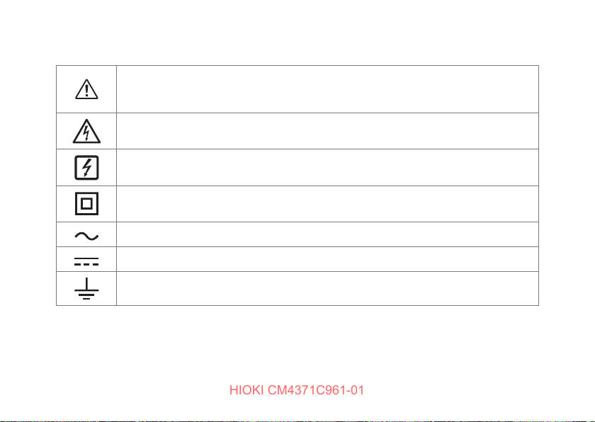
Notations
HIOKI CM4371C961-01
Symbols shown on the instrument
Indicates the presence of a potential hazard. For more information about locations where this
symbol appears on instrument components, see the "Operating Precautions" (p. 12) and
the accompanying document entitled “Operating Precautions.”
Indicates that a dangerous voltage is generated from this terminal.
Indicates that the product can be attached or detached while the circuit is live.
Indicates the instrument is protected throughout by double insulation or reinforced insulation.
Indicates alternating current (AC).
Indicates direct current (DC).
Indicates the grounding terminal.
4
Page 10
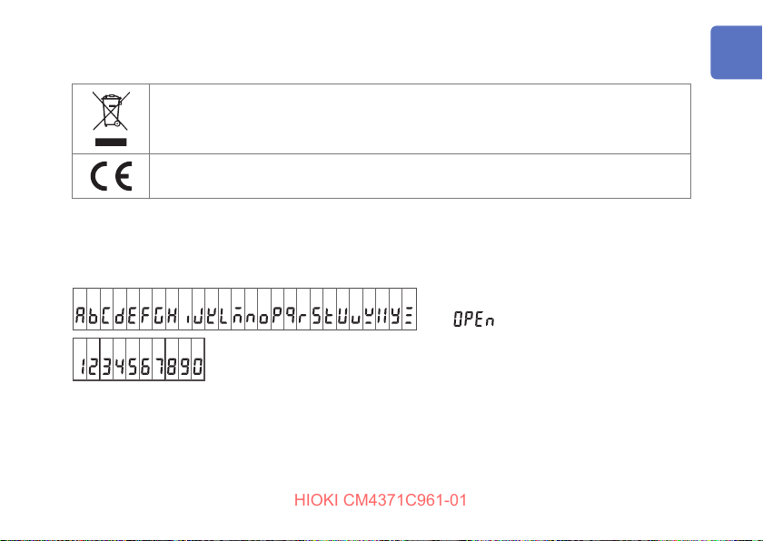
Symbols for various standards
HIOKI CM4371C961-01
Indicates that the product is subject to the Waste Electrical and Electronic Equipment (WEEE)
Directive in EU member nations.
Indicates that the product complies with standards imposed by EU directives.
Screen display
The instrument screen displays the alphanumeric characters as follows.
A B C D E F G H I J K L M N O P Q R S T U V W X Y Z
1 2 3 4 5 6 7 8 9 0
Notations
Exception
: Wire break detected
5
Page 11
Notations
HIOKI CM4371C961-01
Accuracy labeling
Instrument accuracy is expressed by dening a percentage of the reading, a percentage of full scale, a
percentage of the setting, or a limit value for errors in terms of digits.
Reading
(display value)
Full scale
(maximum
display value)
Other notations
(p. )
*
CM4371
-50
6
Indicates the value displayed by the instrument.
Limit values for reading errors are expressed as a percentage of the reading (“% rdg”).
Indicates the maximum display value for each measurement range. Measurement range
values for the instrument indicates that maximum display value. Limit values for full-scale
errors are expressed as a percentage of full scale (“% f.s.”).
Indicates the page number to reference.
Indicates additional information is described below.
Indicates that the item is applicable to the CM4371-50 only.
Page 12
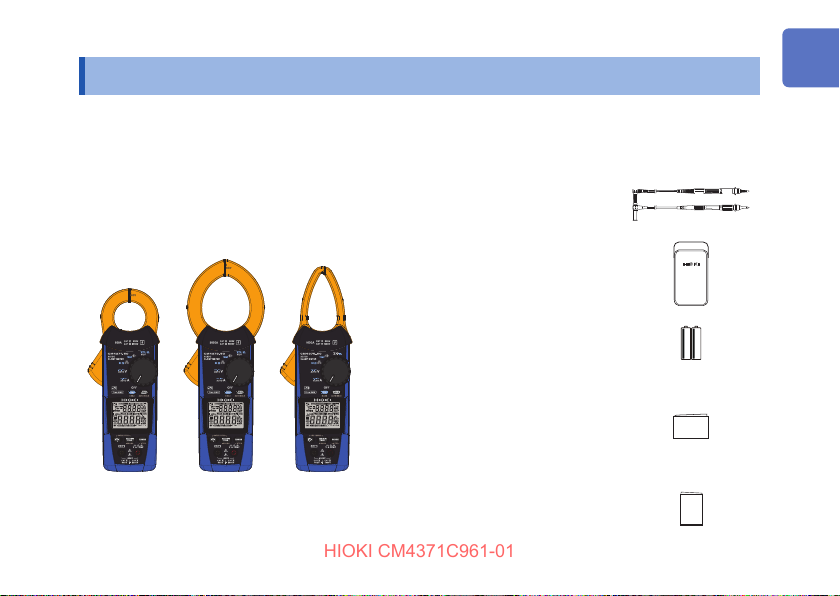
Checking Package Contents
HIOKI CM4371C961-01
When you receive the instrument, inspect it to ensure that no damage occurred during
shipment. Pay particular attention to included accessories, panel keys, and terminals. If you nd
any damage or discover that the instrument does not perform as indicated in its specications,
please contact your authorized Hioki distributor or reseller.
AC/DC Clamp Meter
CM4373-50
CM4371-50
CM4375-50
Checking Package Contents
L9300 Test Lead
(p. 27)
C0203 Carrying Case
LR03 Alkaline batteries ×2
Instruction Manual
(this manual)
Please visit Hioki's website to
download other language versions in
PDF format.
Operating Precautions
(0990A907)
7
Page 13
Options
HIOKI CM4371C961-01
Options
The options listed below are available for the instrument. To order an option, please contact your
authorized Hioki distributor or reseller.
Options are subject to change. Check Hioki’s website for the latest information.
Connection cables
When attaching the L4933 or L4934 to test leads, set the test leads
to the measurement category II conguration (for the L9207-10,
remove the sleeves).
L4933 Contact Pin Set*
3
L9300 Test Lead*
1
L9207-10 Test Lead*
8
1
L4934 Small Alligator Clip Set*
4
Page 14
Options
HIOKI CM4371C961-01
L4930 Connection Cable Set*2
(length: 1.2 m)
L4931 Extension Cable Set*2
(length: 1.5 m,
with the coupling connector)
DT4910 Thermocouples (K)
P2000 DC High Voltage Probe*
*1: CAT IV 600 V, CAT III 1000 V, CAT II 1000 V, 10 A *7: CAT III 1000 V, 2 A
*2: CAT IV 600 V, CAT III 1000 V, 10 A *8: CAT III 600 V, CAT II 600 V, 10 A
*3: 30 V AC, 60 V DC, 3 A *9: CAT III 600 V, 10 A
*4: CAT III 300 V, CAT II 600 V, 3 A *10: CAT IV 1000 V, 2 A
*5: CAT II 1000 V, 1 A *11: CAT IV 1000 V, CAT III 2000 V
*6: CAT III 600 V, 5 A
L4935 Alligator Clip Set*
L9243 Grabber Clip*
L4936 Bus Bar Clip Set*
L4937 Magnetic Adapter Set*
9804 Magnetic Adapter*
L4932 Test Pin Set*
L4938 Test Pin Set*
11
L4939 Breaker Pin Set*
2
5
6
7
10
1
8
9
9
Page 15
Options
HIOKI CM4371C961-01
Carrying cases
The instrument, test leads, and the instruction manuals can be accommodated.
C0203 Carrying Case C0207 Carrying Case
Z3210 Wireless Adapter
Connecting the Z3210 to the instrument enables the wireless
communication function.
See “2.8 Wireless communications function” (p. 51).
10
Page 16
Safety Information
HIOKI CM4371C961-01
Measurement categories
The instrument conforms to the safety requirements for CAT III 1000 V and CAT IV 600 V
measuring instruments.
Service entrance
Service drop
CAT IV
(≤600 V)
Power meter
Distribution
panel
Internal wiring
CAT III
(≤1000 V)
Fixed installation
Safety Information
CAT II
(≤1000 V)
T
Outlet
11
Page 17
Operating Precautions
HIOKI CM4371C961-01
Operating Precautions
Observe the following precautionary information to ensure that the instrument can be used
safely and in a manner that allows it to perform as described in its specications. Carefully
read the separate document entitled “Operating Precautions” before use. Use of the instrument
should conform not only to its specications, but also to the specications of all accessories,
options, and other equipment in use.
Do not touch the section beyond the barrier during operation.
Do not measure any current in excess of the derating curve.
12
DANGER
Failure to do so could cause the operator to experience an electric shock.
See “1.2 Part Names” (p. 20).
Doing so can cause overheating of the sensor, resulting in bodily injury, re, or
damage to the instrument.
See "Frequency derating characteristics" (p. 68).
The maximum measurement current varies with the frequency, and the current
that can be measured continuously is limited. Operating the instrument at less
than this limitation is referred to as derating.
Page 18
Inspect the instrument and verify proper operation before
HIOKI CM4371C961-01
use.
Conrm that the white portion (insulation layer) inside the
cable is not exposed.
Operating Precautions
DANGER
Use of the instrument while malfunctioning could result in serious bodily injury.
If you nd any damage, contact your authorized Hioki distributor or reseller.
See “2.1 Inspection Before Measurement” (p. 21).
Using the instrument with a color inside its cable exposed could cause the
operator to experience an electric shock.
13
Page 19
Operating Precautions
HIOKI CM4371C961-01
Do not allow the instrument to get wet.
Do not take measurements with wet hands.
When using the instrument while connected to test leads,
do not make measurements that exceed either of the ratings
indicated on the instrument or on the test leads, whichever is
lower.
14
WARNING
Failure to do so could cause the operator to experience an electric shock.
Using the instrument to make measurements that exceed either rating could
cause the operator to experience an electric shock.
Page 20
IMPORTANT
HIOKI CM4371C961-01
Operating Precautions
Do not allow any foreign object to be caught between the
facing core surfaces of the jaws.
Do not scratch the facing core surfaces of the jaws.
Do not touch the facing core surfaces of the jaws with your
ngers.
Do not insert any foreign object into the gap of the jaws.
Do not drop the instrument.
Do not subject the instrument to any shock.
Doing so may adversely aect the measurement accuracy and open/
close operation.
Clamp the instrument around only one conductor. Clamping the instrument
around two or more of conductors in a bundle prevents the instrument from
measuring any current regardless of whether the measurement target is a
single-phase or three-phase circuit.
15
Page 21
Operating Precautions
HIOKI CM4371C961-01
L4937 Magnetic Adapter Set / 9804 Magnetic Adapter (optional)
People with electronic medical devices such as pacemakers
should not use the magnetic adapter.
Keep the magnetic adapter away from the body.
16
DANGER
Failure to do so may aect proper operation of the electric medical devices,
presenting a hazard to human life.
Page 22
Do not drop the magnetic adapter.
HIOKI CM4371C961-01
Do not subject the magnetic adapter to mechanical shock.
Do not use the magnetic adapter in locations where it may be
exposed to rainwater, dust, or condensation.
Do not bring the magnetic adapter near magnetic storage devices,
such as oppy disks, magnetic cards, prepaid cards, or magnetized
tickets.
Do not bring the magnetic adapter near precision electronic
equipment, such as computers, TV screens, or electronic wrist
watches.
Operating Precautions
CAUTION
Doing so could damage the magnetic adapter.
Doing so could decompose or deteriorate the magnetic adapter. In addition,
diminished magnetic adhesion cause the instrument to drop, resulting in
damage to the instrument.
Doing so could damage such devices or data stored in them.
17
Page 23

Operating Precautions
HIOKI CM4371C961-01
18
Page 24
1
HIOKI CM4371C961-01
Overview
1.1 Product Overview and Features
This instrument is a clamp meter that can
perform true RMS measurement of current
simply by clamping it around a circuit. In
addition to current, it can measure voltage,
frequency, rush current, resistance, diode,
capacitance, temperature , and AC power.
Installing the Z3210 Wireless Adapter
(optional) to the instrument allows your mobile
device to display waveforms and measure
harmonics.
Measurement function list
DC current and DC voltage, DC
power
Electric charge detection
CM4371
-50
Capacitance, temperature
Continuity check, resistance, diode
Automatic AC/DC, AC voltage, DC
voltage, AC+DC voltage, frequency
Automatic AC/DC, AC current, DC
current, AC+DC current, frequency
CM4373
-50
19
Page 25
Part Names
HIOKI CM4371C961-01
1.2 Part Names
Front Rear
1
2
(The illustration shows the CM4375-50.)
20
1 Operation grip
2 Fn key (allows you to choose a function)
3
4
5
6
7
8
9
10
11
12
3 Jaws
4 Barrier
5 Serial number (The serial number
consists of 9 digits. The rst two (from
the left) indicate the year of manufacture,
and the next two indicate the month of
manufacture.)
6 Rotary switch
See “Measurement function list” (p. 19).
7 HOLD key
8 LCD
9 Battery cover
10 Operation keys
11 Measurement terminals
12 Strap hole
Page 26
2
NO
NONO
HIOKI CM4371C961-01
Making Measurements
2.1 Inspection Before Measurement
Check Inspection details Check Inspection details
The battery cover is closed and its screw
has been securely tightened.
There is no foreign matter on the
measurement terminals (p. 20).
The test leads are not broken (p. 43).
There is no damage to the test lead
insulation, and neither the white sheathing
nor metal conductor inside the wire are
exposed.
The instrument is neither damaged nor
cracked.
No segments are missing.
OK
1 Ω or less
(All segments appear)
21
Page 27
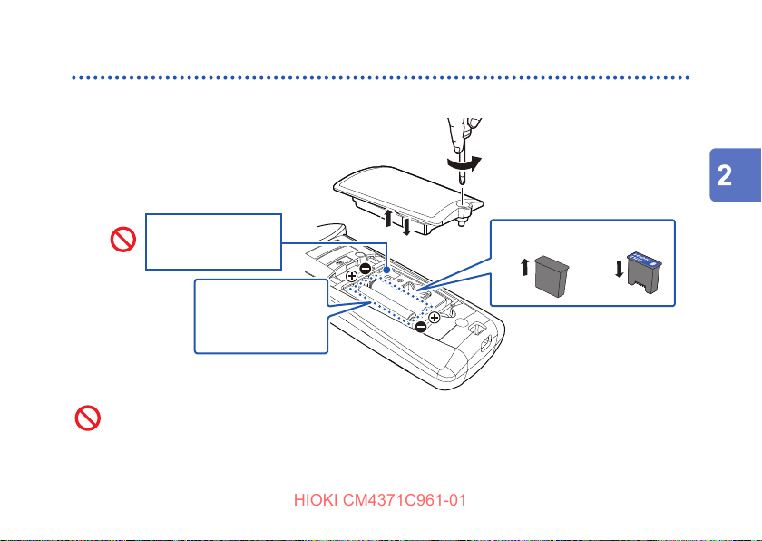
Installing Batteries and the Z3210 Wireless Adapter
HIOKI CM4371C961-01
2.2 Installing Batteries and the Z3210 Wireless Adapter
Installing the Z3210 to the instrument enables the wireless communications function. (p. 51)
Before removing the battery cover, remove the instrument
from an object under measurement and set the rotary switch
to the OFF position.
22
WARNING
Failure to do so could cause the operator to experience an electric shock. When
the instrument is clamped around the object under measurement, the battery
contact terminals are regarded as high-voltage parts.
Page 28
After replacing the batteries or installing/removing the Z3210
HIOKI CM4371C961-01
Wireless Adapter, install the battery cover and tighten the
screw, then use the instrument.
Secure the battery cover with the screw attached to the
instrument at the time of shipment.
Installing Batteries and the Z3210 Wireless Adapter
WARNING
Use of the instrument with the battery cover removed could result in bodily
injury.
If you have lost the screw or nd that the screw is damaged, please contact your
authorized Hioki distributor or reseller.
23
Page 29
Installing Batteries and the Z3210 Wireless Adapter
HIOKI CM4371C961-01
CAUTION
Do not mix batteries of dierent ages or types.
Do not use a battery whose recommended service life has expired.
Do not reverse the battery polarity.
Do not leave the exhausted batteries in the instrument.
Doing so may cause the batteries to leak, damaging the instrument.
Use the specied type of batteries only (LR03 Alkaline batteries).
Remove the batteries when the instrument is not in use for an
extended period of time.
Doing so may cause the batteries to leak, damaging the instrument.
Before handling the Z3210, eliminate static electricity on your body
by touching any metallic part, such as a doorknob.
Failure to do so may cause static electricity to damage the Z3210.
• When the
ones in good time. The instrument may be turned o when the display is backlighted or the
buzzer sounds. After use, be sure to turn o the instrument.
• Dispose of the batteries in accordance with local regulations.
24
mark blinks, the batteries will be exhausted. Replace the batteries with new
Page 30
Installing Batteries and the Z3210 Wireless Adapter
HIOKI CM4371C961-01
Installation procedure
Read the precautions before performing the procedure. (p. 22)
You will need:
Phillips screwdriver (No. 2)
Measurement value
adjusting screws ×3
Do not turn.
NO
Do not turn any screws except the battery cover screw.
After removing the battery cover, you will nd three screws, which are used to adjust
NO
measured values. Do not turn them because the instrument will not be able to perform
measurement accurately.
3, 4
LR03
Alkaline batteries ×2
2
7
22
77
Z3210
Protective cap
5
6
25
Page 31

Installing Batteries and the Z3210 Wireless Adapter
HIOKI CM4371C961-01
Remove the instrument from an object under measurement and set the rotary
1
switch to the OFF position.
2
Loosen the screw and remove the battery cover.
3
Remove the old batteries (when replacing the batteries).
4
Install fresh batteries, observing the correct polarity.
When installing the Z3210 Wireless Adapter, go on to step 5.
When not installing the Z3210 Wireless Adapter, go on to step
5
Remove the protective cap from the instrument.
6
Install the Z3210 Wireless Adapter, observing the correct orientation.
7
Reattach the battery cover and tighten the screw.
26
.
7
Page 32

2.3 Use of Test Leads
HIOKI CM4371C961-01
The L9300 Test Lead (accessory) or the L9207-10 Test Lead (optional) is used for measurement.
Depending on measurement locations, use Hioki’s optional measurement cables.
See “Options” (p. 8)
When using the instrument, use the test leads and options
specied by Hioki.
When measuring the power line voltage, use test leads that
satisfy the following conditions.
Failure to do so could cause the operator to experience an electric shock.
The optional test leads for this instrument comply with the EN 61010 safety
standard. Observe the measurement category and rated voltage indicated on the
test leads during use.
Use of Test Leads
WARNING
Using test leads and options other than those specied could cause bodily injury
or short circuit accidents.
• IEC 61010 or EN 61010 safety standard-compliant
• Rated for measurement category III or IV
• With the rated voltage higher than voltage being measured
27
Page 33

Use of Test Leads
HIOKI CM4371C961-01
Do not bend the cables at temperatures of 0°C or lower. Do not pull
on the cables.
28
CAUTION
The cables can become rigid. Doing so could damage the insulation or cause a
wire break, resulting in an electric shock.
Page 34

L9300 Test Lead (accessory)
HIOKI CM4371C961-01
See the precautions in “Use of Test Leads” (p. 27) as well.
Use the test leads with the correct measurement category
displayed.
Do not use the test leads if the metal pin is bent or the
protective nger guard does not slide properly.
Use of Test Leads
WARNING
Doing so could cause short circuit accidents.
29
Page 35

Use of Test Leads
HIOKI CM4371C961-01
Switching the measurement category
Unlock the protective nger guard.
1
Rotate the grip to unlock, moving the mark along the guide line.
Slide the protective nger guard.
2
30
Protective nger guard
mark
Slide the mark along the
guide line.
Guide line
Page 36

Lock the protective nger guard.
HIOKI CM4371C961-01
3
Rotate the grip to lock, moving the mark
along the guide line.
Rotate the grip until it clicks, and make sure
that the mark indicates [LOCKED].
Perform the above steps to switch over from measurement category II to measurement category
III or IV as well.
Use of Test Leads
31
Page 37

Current Measurement
HIOKI CM4371C961-01
2.4 Current Measurement
11
22
Hold down for 1 s.
IMPORTANT
Always perform zero
adjustment to perform accurate
measurement.
32
Zero adjustment
33
Clamp the instrument around the wire.Rotate the rotary switch.
44
(Auto AC/DC)
Example:
3P3W circuit breaker (AC current range)
Current direction
Current direction
arrow
Match the current direction arrow
with the current direction.
(AC A)
(AC+DC A)(DC A)
(Freqency)
HzAUTO
Page 38

Frequency detection range for AC current
HIOKI CM4371C961-01
Current Measurement
CM4371-50
CM4373-50
CM4375-50 — 5.0 A or more
DC voltage polarity check (p. 59)
If the measured value is negative, the buzzer will sound and the display will be backlighted in red.
(threshold: −10 A)
20.00 A range 4.00 A or more
600.0 A range 20.0 A or more
600.0 A range 40.0 A or more
2000 A range 200 A or more
33
Page 39

Current Measurement
HIOKI CM4371C961-01
Manual hold, automatic hold
Manual hold Automatic hold
Illuminate
Press the HOLD key again to disable
the hold function.
34
The measured value
freezes.
Hold down for
1 s.
(
the value has stabilized)
Illuminate
The measured value freezes automatically.
Holding down the HOLD key for 1 s to disable the
automatic hold function.
Flash
Clamp the instrument
around the wire.
appears when
Remove
Page 40

Automatic hold conditions
HIOKI CM4371C961-01
Displayed value will freeze when the following two conditions are satised at the same time:
• When the measured value uctuation stabilizes within the uctuation range described in the table on the
next page.
• When the measured value exceeds the threshold value described in the table on the next page (voltage,
current).
When the measured value is less than the threshold value described in the table on the next page (resistance,
continuity check, diode).
Measured
value
Suppose that the measured value has fallen below (voltage, current) or exceeded the threshold value
(resistance, continuity, diode) after the displayed value froze. When the two auto-hold conditions are met
again after that, refreshing measured values will stop.
Start
Automatic hold,
e.g., 100.0 A
(1)
End
Start
(2)
End
Start
Automatic hold
e.g., 99.0 A
(1) Not frozen automatically
(2) Not frozen automatically
Threshold value
e.g., 12.0 A
Time
End
Current Measurement
(Does not fall below threshold.)
(Does not exceed threshold.)
: Fluctuation range
: Measured value to be frozen
35
Page 41

Current Measurement
HIOKI CM4371C961-01
Measurement
function*
Auto A
AC current
DC current
AC+DC current
1
Measurement
range
20.00 A range
(CM4371-50)
600.0 A range
(CM4371-50,
CM4373-50)
Fluctuation range Threshold value
Within 1.00 A 1.00 A
Within 12.0 A 12.0 A
36
1000 A range
(CM4375-50)
2000 A range
(CM4373-50)
Within 12.0 A
(When inputting more than
12.0 A)
Within 1.0 A
(When inputting more than
12.0 A)
Within 40 A 40 A
12.0 A
(When inputting more than
12.0 A)
0.9 A
(When inputting more than
12.0 A)
Page 42

Measurement
HIOKI CM4371C961-01
function*
Auto V*
AC voltage
DC voltage*
AC+DC voltage
DC High V Probe Mode 600.0 V range Within 12.0 V 80.0 V
1
2
2
Measurement
range
6.000 V,
60.00 V, 600.0 V
range
1000 V range Within 20 V 20 V
2000 V range Within 20 V 80 V
Fluctuation range Threshold value
Within 120 counts 120 counts
Current Measurement
Continuity check
Resistance
Diode 1.800 V range Within 0.040 V 1.460 V
*1: The automatic hold function does not support measurement functions not listed in this row.
*2: Except the 600.0 mV range (only when the range is set manually)
600.0
6.000 k
60.00 k
600.0 k
6.000 M
range,
Ω
range,
Ω
range,
Ω
range,
Ω
Ω
Within 100 counts 4900 counts
range
37
Page 43

Current Measurement
HIOKI CM4371C961-01
Switching the ranges
When the CM4373-50 measures current
Automatic range Manual 2000 A rangeManual 600.0 A range
When the CM4371-50 measures current
Automatic range Manual 600.0 A rangeManual 20.00 A range
The CM4375-50 provides the 1000 A range only.
38
Page 44

Filter function
HIOKI CM4371C961-01
Filter o Filter on
Measured value including noise Measured value with reduced noise
Frequency characteristics when the lter
function is enabled
(100 A input)
Measured value (A)
Filter o
Filter on, pass band 100 (Hz)
Frequency (Hz)
Hold down
for 1 s.
Current Measurement
Disable the lter function when performing
measurement of power supply frequencies
in excess of 100 Hz, for example, on an
aircraft or ship.
Filter o
39
Page 45

Current Measurement
HIOKI CM4371C961-01
Maximum value, minimum value, average, and peak value
11
Clamp the instrument
around the wire.
MAX, MIN, AVG,
22
(Auto AC/DC)
(AC A)
(AC+DC A)(DC A)
HzAUTO
(Frequency)
and PEAK are
unavailable in Auto
AC/DC mode.
33
44
The instrument
measures RMS
values.
AVG indicates
the average of all
measured values.
40
The measured value
freezes.
Peak min.
Peak max.
Max.
Hold down for 1 s.
Cancel
Wavwform
Min.
Measured
value
(RMS)
Display refresh
interval
Page 46

Inrush current (inrush)
HIOKI CM4371C961-01
Current Measurement
11
Turn o the motor.
22
Rotate the rotary switch.
33
Hold down for 1 s.
Clamp the instrument
44
around the wire.
See “Inrush trigger level” (p. 67).
55
Set the range.
See “Switching the ranges” (p. 38).
In automatic ranging mode, the instrument
will be automatically set to the 600.0 A range
(CM4371-50), 2000 A range (CM4373-50).
Zero adjustment
66
Hold down for 1 s.
Inrush on
77
Turn the motor on.
To exit inrush mode
Hold down
for 1 s.
RMS value (inrush)
e.g., 100 A
AC current
e.g., 250 A
AC inrush peak value
Inrush current occurrence period
(about 10 ms to 999 ms)
(Inrush current occurs)
RMS value (inrush)
DC current
AC inrush peak value
Inrush current occurrence period
(about 10 ms to 999 ms)
41
Page 47

Various Other Measurement Functions
HIOKI CM4371C961-01
2.5 Various Other Measurement Functions
Voltage measurement
e.g., Commercial power supply (AC voltage)
33
Switching ranges (p. 38)
11
11
Do not apply
excessive voltage.
NO
(Flash in red)
42
Black Red
Do not touch.
NO
22
AUTO
Hz
(Auto AC/DC)
(AC V)
(DC V)
(AC+DC V)
(Frequency)
DC voltage polarity check (p. 59)
If the measured value is negative, the buzzer
will sound and the display will be backlighted
in red. (threshold: −10 V)
Page 48

Various Other Measurement Functions
HIOKI CM4371C961-01
Continuity check Resistance measurement Diode measurement
2
Zero adjudtment
2
Zero adjustment
1 1
Black
(Backlighted in red)
See the specications for the
short-circuit and open-circuit
detecting thresholds (p. 72).
Red
3
Hold down
for 1 s.
Black
Hold down
for 1 s.
3
Red
If resistance values of
coils, including motors and
transformers, measured with
the auto-ranging uctuate,
select the range manually.
Black
Red
43
Page 49

Various Other Measurement Functions
HIOKI CM4371C961-01
Capacitance measurement Temperature measurement
Black Red
Type K thermocouples exhibit a physical
phenomenon known as short range ordering,
which can cause inaccurate measurements
in the range of 250°C to 600°C.
44
+−
Black Red
To switch the
temperature units,
see p. 60.
DT4910
Thermocouples (K)
: The DT4910 is broken
(or not connected).
Page 50

Various Other Measurement Functions
HIOKI CM4371C961-01
Electric charge
detection
CM4371
See"5.1 Voltage Detection
Function" (p. 111)
Bring the jaw close a
power line.
To switch the sensitivity.
(High/low) (p. 101)
CM4373
-50
(Illuminate in red)
Simultaneous display of
DC current and DC voltage
-50
e.g., Checking a car battery
Switch the ranges using the
RANGE key.
RedBlack
CM4375-50
DC power
measurement
e.g., Maintenance for a
solar power system
RedBlack
45
Page 51

LCD Backlight, Automatic Power Save (APS)
HIOKI CM4371C961-01
2.6 LCD Backlight, Automatic Power Save (APS)
LCD backlight Automatic power save
Backlight o
Backlight on
Automatically shut o after 40 s
of inactivity
46
(Always on)
How to cancel: p. 59
After 15 minutes
of inactivity
You can turn the display back on by
pressing a key or by rotating the rotary
switch.
After 45 minutes of inactivity
The instrument is automatically turned o.
Set the rotary switch to the OFF position to restart.
Page 52

2.7 DC High V Probe Mode
HIOKI CM4371C961-01
Use of the P2000 DC High Voltage Probe (optional) allows you to measure DC voltage of up to
2000 V (CAT III 2000 V, CAT IV 1000 V), such as open voltage of solar panels.
Do not use the P2000 to measure AC voltage.
Do not measure voltage that exceeds 2000 V DC.
Use the P2000 to measure voltage that exceeds 1000 V.
Connect the instrument and the P2000 together with the strap when
using the L4943.
DC High V Probe Mode
WARNING
The probe cannot accurately measure AC voltage. Improper measurement could
lead to electric shock. You can use the P2000 for DC voltage measurement
only.
Doing so could damage the instrument and the P2000, causing bodily injury.
Use of other probes could cause the operator to experience an electric shock.
CAUTION
The cables and plugs will be subjected to stress, damaging them.
47
Page 53

DC High V Probe Mode
HIOKI CM4371C961-01
When using the L4943 Connection Cable Set*
33
11
Disconnect the clip* from the strap
buckle* as shown in the gure.
Clip
22
Attach the strap* to the P2000.
For details, see the P2000 Instructon manual.
Strap
Attach the strap buckle to the instrument
and connect it to the clip that you
attached to the P2000 with the strap.
*: Supplied with the P2000.
48
-2-2
-1-1
-3-3
When using the L4930 Connection Cable
Set or the L4931 Extension Cable Set
(optional)
Hang the P2000 in some way, such as using a
magnetic strap, not to subject the cables and
the plugs to stress.
Page 54

Making Measurements
HIOKI CM4371C961-01
Rotate the rotary switch.
11
or
22
Hold down the two keys for
1 s as described below.
DC High V Probe mode On
Connect the P2000 DC High Voltage Probe to the
33
measurement terminals of the instrument.
44
Set the range.
See “Switching the ranges” (p. 38).
DC High V Probe Mode
55
N (−)
P (+)
P2000 probes
Flash
44
Red
Black
33
OUTPUT
55
Bring the probes into
contact with an object to
be measured.
49
Page 55

DC High V Probe Mode
HIOKI CM4371C961-01
Saving the DC High V Probe mode settings
Turn o the instrument, and then set the rotary switch to other than the OFF position while holding down the
two operation keys as described below.
• The DC High V Probe mode start-up setting can be toggled between on and o. (p. 59)
• When the DC High V Probe mode start-up is enabled, the instrument will start in the mode you last used.
50
(Any position)
Page 56

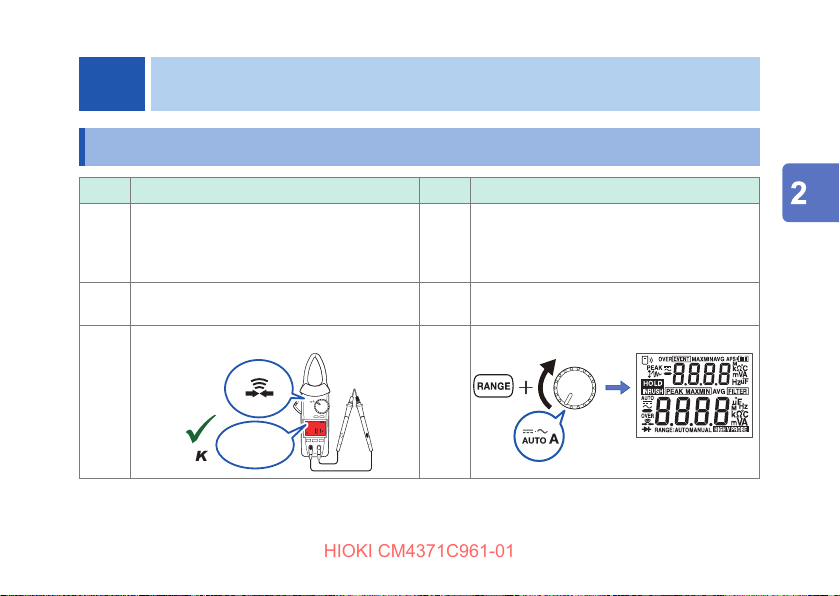
2.8 Wireless communications function
HIOKI CM4371C961-01
Installing the Z3210 Wireless Adapter (optional) is required.
Concurrent use of GENNECT Cross and HID function (p. 55) is not available.
Using GENNECT Cross
Enabling the wireless communications function allows you to check and record the measured
data of the instrument, and create measurement reports using your mobile device. For details,
see the operation guide for the GENNECT Cross app (free of charge).
Wireless communications function
GENNECT Cross special site
https://gennect.net/en/cross/index
51
Page 57

Wireless communications function
HIOKI CM4371C961-01
Using the wireless communications function
Connect the Z3210 Wireless Adapter (option) into the instrument. (p. 22)
1
Install GENNECT Cross on your mobile device.
2
Turn on the instrument.
3
Enable the wireless communications function.
4
When the instrument is turned on for the rst time after the Z3210 has been installed, the wireless
communications function will be enabled.
O
(Default
setting)
Start GENNECT Cross and register the connection of the instrument.
5
• When GENNECT Cross is started for the rst time (when there is no registered instrument), the
Instrument Settings screen appears.
• When the instrument is placed near your mobile device, its connection is registered automatically on
the Instrument Settings screen of GENNECT Cross (up to eight instruments).
• Wait for 5 to 30 s until the connection of the instrument is registered after turning on the instrument. If
the connection of the instrument is not registered after 1 minute has elapsed, restart GENNECT Cross
and the instrument.
Select a measurement function to perform measurement.
6
52
Hold down for 1 s.
appears:
Wireless communications
function enabled
O: Wireless communications function disabled
Blinks: During wireless communications
Page 58

• The communication distance is about 10 m with a clear line of sight. The communicable
HIOKI CM4371C961-01
distance may vary greatly depending on the presence of an obstruction (wall or metallic
shielding object) and the distance between the oor (ground) and instrument. To ensure the
stable communication, make sure that the radio wave intensity is sucient.
• GENNECT Cross is free of charge. However, the customer is responsible for the cost to
download the application software and connect to the Internet when using the software.
• GENNECT Cross may not operate properly depending on the mobile device.
• The Z3210 uses the 2.4 GHz band wireless technology.
When there is a device that uses the same frequency band such as a wireless LAN (IEEE
802.11.b/g/n) near your mobile device, the communication may not be established.
When the instrument is placed on the oor or ground, the communication distance becomes shorter. It is
recommended that you move the instrument away from the oor or ground and place it on a desk or table
or hold it by hand.
Wireless communications function
53
Page 59

Wireless communications function
HIOKI CM4371C961-01
Event recording function
The event recording function logs the data when a measured value exceeds a desired threshold
value, which can be set with GENNECT Cross. For details, see the operation guide for the
GENNECT Cross app (free of charge). The number of recorded events can be checked using
the instrument.
Hold down the
two keys for 1 s
as described
above.
54
Event count
display
• Up to 99 events can be recorded. If events has
reached 99, the event recording will stops.
When another event recording starts,
previously recorded data will be deleted.
• Some events with a duration time of less than
400 ms may not be accurately measured,
failing to detect them.*
* Current frequency, voltage frequency,
capacitance (400 ms to 4000 ms, depending
on measured value), temperature (type K
thermocouple) 2000 ms
Page 60

Z3210-to-Excel® direct data entry function (Excel® direct input function,
HIOKI CM4371C961-01
HID function)
Concurrent use of GENNECT Cross and HID function is not available.
The human interface device (HID) prole, with which the Z3210 Wireless Adapter is equipped, is
a prole same as that wireless keyboards use.
HID ON
HID OFF
The setting whether the HID function has been enabled or disabled will not be saved in the
instrument but in the Z3210.
Wireless communications function
Preparatory to data entry, open an Excel® le on your mobile device or computer and
choose a cell. When the instrument’s display freezes, the measured values will be
entered on the cells. The use of this function with the automatic hold function enabled
comes in handy. (p. 34)
When you wish to use GENNECT Cross, disable the HID function.
Measured value is entered.
55
Page 61

Wireless communications function
HIOKI CM4371C961-01
Conrming the HID setting
Remove the test leads from the object under measurement.
1
Set the rotary switch to the OFF position.
2
Connect the Z3210 Wireless Adapter (option) into the instrument. (p. 22)
3
Conrm the HID setting.
4
Make sure that the instrument is turned o, and then set the rotary switch to the TEMP position while
holding down the
The settings stored in the Z3210
will be displayed.
When [− − − − ] appears
Update the Z3210 rmware to the latest version using GENNECT Cross (version 1.8 or later)..
To change the HID setting, use the procedure on the following page.
56
key.
or
Page 62

Changing the HID setting
HIOKI CM4371C961-01
Turn o the instrument.
1
Chang the HID setting.
2
Make sure that the instrument is turned o, and then set the rotary switch to any position while holding
down both the
After exhibiting the following displays, the instrument is automatically turned o.
Turn on the instrument again.
3
The HID setting will be toggled.
Wireless communications function
key and the key.
(Any position)
The instrument is
automatically turned
o.
57
Page 63

Wireless communications function
HIOKI CM4371C961-01
IMPORTANT
To switch over from the HID function to GENNECT Cross
If you start GENNECT Cross without canceling the paring between the mobile device and the
instrument, GENNECT Cross may not be able to recognize the instrument as a connectible
device. Follow the procedure below to reconnect the instrument to GENNECT Cross.
Use the Bluetooth
1. Disable the Z3210’s HID function. (p. 57)
2. Use the Instrument Setting of GENNECT Cross to reconnect the instrument.
Check Hioki’s website for the latest information.
https://z3210.gennect.net
58
®
setting of your mobile device to delete the instrument.
Page 64

2.9 Rotary Switch Combinations
HIOKI CM4371C961-01
Rotary Switch Combinations
+
Auto-power save (APS) function cancel
DC current/voltage, polarity check on/o Any position
LCD all segments display*
version number*
four digit)*
check (Z3210 required)*
Buzzer (on/o)
Automatic backlight shuto (on/ o) Any position
DC High V Probe mode setting saving
(on/o)
Turn o the instrument, and then turn it on again while holding down one or
two operation keys.
(Set the rotary switch to other than the OFF position)
1
, serial number*1, HID setting
Setting Procedure
1
1
, model number (only last
, rmware
1
Factory-
shipped
setting
Any position On Not saved
O Saved
Any position − −
Any position On Saved
On Saved
O Saved
Any position
Saving of
setting
59
Page 65

Rotary Switch Combinations
HIOKI CM4371C961-01
Setting Procedure
Toggling the HID setting (on/o)
(Z3210 required)
Factory-
shipped
setting
− −*
Saving of
setting
2
Switching between the two temperature
units: degrees Celsius and degrees
Fahrenheit
*1: The screen display depends on the rotary switch position.
*2: The setting whether the HID function has been enabled or disabled will not be saved in the instrument but
in the Z3210.
60
Hold down for 1 s.
To switch the
temperature units
To save the setting
Hold down for 1 s.
Degrees
Celsius
Saved
Page 66

3
HIOKI CM4371C961-01
Specications
3.1 General Specications
Operating
environment
Operating
temperature and
humidity range
Storage temperature
and humidity range
Indoor use, pollution degree 2, altitude up to 2000 m (6562 ft.)
−25°C to 65°C (−13°F to 149°F), 90% RH or less (non-condensing)
−30°C to 70°C (−22°F to 158°F), 90% RH or less (non-condensing, with batteries
removed)
61
Page 67

General Specications
HIOKI CM4371C961-01
Dust resistance and
water resistance
Standards Safety EN 61010
62
IP20 (When measuring voltage under completely dry conditions, when measuring
current owing through a hazardous live conductor under completely dry
conditions)
IP50 (When measuring resistance under completely dry conditions)
IP54 (When measuring current owing through an insulated conductor, during
storage)
The protection rating for the enclosure of this instrument (based on EN60529) is
IP20*, IP50*, or IP54*.
* IP20, IP50, IP54:
This indicates the degree of protection provided by the enclosure of the device for
use in hazardous locations, entry of solid foreign objects, and the ingress of water.
2: Protected against access to hazardous parts with a ngers. The equipment
inside the enclosure is protected against entry by solid foreign objects larger
than 12.5 mm in diameter.
5: Protected against access to hazardous parts with wire measuring 1.0 mm
in diameter. Dustproof type (The penetration of dust cannot be prevented
completely, but quantities of dust that may hinder the stated operation of
equipment or safety cannot penetrate the enclosure.)
0: The equipment inside the enclosure is not protected against the harmful eects
of water.
4: The equipment inside the enclosure is protected against the harmful eects of
water splashed against the enclosure from any direction.
EMC EN 61326
Page 68

Power supply LR03 Alkaline batteries ×2
HIOKI CM4371C961-01
Continuous
operating time
Dimensions*
3
Jaw dimensions CM4371
Jaw cross-sectional
minimum dimension
Rated supply voltage: 1.5 V DC × 2
1
-50
*
CM4371
About 40 hours (without the Z3210)
About 20 hours (with the Z3210 installed and wirelessly
communicating)
2
-50
*
CM4373
About 40 hours (without the Z3210)
About 24 hours (with the Z3210 installed and wirelessly
communicating)
2
-50
*
CM4375
About 40 hours (without the Z3210)
About 20 hours (with the Z3210 installed and wirelessly
communicating)
-50
CM4371
CM4373
CM4375
CM4373
CM4375
CM4375
-50
-50
-50
-50
-50
-50
Approx. 65W × 216H × 35D mm (2.56″W × 8.50″H × 1.38″D)
Approx. 65W × 250H × 35D mm (2.56″W × 9.84″H × 1.38″D)
Approx. 65W × 242H × 35D mm (2.56″W × 9.53″H × 1.38″D)
Approx. 69Wj × 14Dj mm (2.72″W × 0.55″D)
Approx. 92Wj × 18Dj mm (3.62″W × 0.71″D)
Approx. 53Wj × 20Dj mm (2.09″W × 0.79″D)
Approx. 9.5 mm (0.37″)
General Specications
63
Page 69

General Specications
HIOKI CM4371C961-01
Maximum
measurable
conductor diameter
Weight CM4371
Product warranty
duration
Accessories p. 7
Options p. 8
*1: Other prescribed conditions
When measuring 10 A AC, with the LCD not backlighted, values for reference purposes at 23°C
*2: Other prescribed conditions
When measuring 100 A AC, with the LCD not backlighted, values for reference purposes at 23°C
*3: The Jaw is not included in the dimensions of width and depth but in that of height.
64
-50
CM4371
-50
CM4373
-50
CM4375
-50
-50
CM4373
-50
CM4375
3 years or until the jaw open/close cycles reaches 30,000, whichever comes rst
33 mm
φ
55 mm
φ
34 mm
φ
Approx. 340 g (12.0 oz., including batteries)
Approx. 530 g (18.7 oz., including batteries)
Approx. 350 g (12.3 oz., including batteries)
Page 70

Input Specications, Measurement Specications
HIOKI CM4371C961-01
3.2 Input Specications, Measurement Specications
(1) Basic specications
Measurable range See “3.3 Accuracy table” (p. 75).
Maximum rated voltage
between terminals
Maximum rated line-toground voltage
Measurement method True RMS measurement
Measurement terminals COM terminal, V terminal
(2) Current measurement specications
1000 V AC (up to 1 kHz)
1000 V DC
600 V (measurement category IV)
1000 V (measurement category III)
Anticipated transient overvoltage: 8000 V
Maximum input current As per the frequency derating characteristics (p. 68)
Coupling type AC current*
1
Other current
measurement parameters
AC coupling
DC coupling
65
Page 71

Input Specications, Measurement Specications
HIOKI CM4371C961-01
Display update rate*
Zero-display range Auto A, AC current,
Crest factor Auto A, AC current, AC+DC current, inrush current
66
2
Auto A, AC current,
DC current,
AC+DC current
Current frequency 0.3 to 5.0 times/s (depending on the frequency)
DC power 1 time/s
DC current + DC voltage 2.5 times/s
DC current,
AC+DC current
-50
CM4371
-50
CM4373
-50
CM4375
5 times/s
5 counts or less
20.00 A range
600.0 A range 3 (500.0 A or less)
600.0 A range 3 (500.0 A or less)
2000 A range 2.84 (1000 A or less)
1000 A range
7.5
2.5 (more than 500.0 A but 600.0 A or
less)
2.5 (more than 500.0 A but 600.0 A or
less)
1.42 (more than 1000 A but 2000 A or
less)
1.5 (1000 A or less)
Page 72

Frequency detection
HIOKI CM4371C961-01
input level
Inrush trigger level CM4371
Peak detection time
width
*1: Does not apply to AC detection in Auto A mode.
*2: Does not include range switching time.
*3: 8.00 A or more for 1 Hz ≤ f ≤ 5 Hz
*4: 10.0 A or more for 1 Hz ≤ f ≤ 5 Hz
Input Specications, Measurement Specications
-50
CM4371
-50
CM4373
-50
CM4375
-50
-50
CM4373
-50
CM4375
1 ms or more (with lter disabled)
20.00 A range
600.0 A range
600.0 A range
2000 A range
1000 A range
20.00 A range +2.0 A or more
600.0 A range +10 A or more
600.0 A range +10 A or more
2000 A range +100 A or more
1000 A range +10 A or more
4.00 A or more*
3
20.0 A or more
40.0 A or more
200 A or more
5.0 A or more*
4
Otherwise, −2.0 A or less
Otherwise, −10 A or less
Otherwise, −10 A or less
Otherwise, −100 A or less
Otherwise, −10 A or less
67
Page 73

Input Specications, Measurement Specications
HIOKI CM4371C961-01
Frequency derating characteristics
-50
CM4371
Current to be measured (A)
68
Inputting up to 1061 A of current is allowable for 1 minute or less.
Frequency (Hz)
(66 Hz or less)
Page 74

-50
HIOKI CM4371C961-01
CM4373
-50
CM4375
Input Specications, Measurement Specications
Current to be measured (A)
Frequency (Hz)
Current to be measured (A)
Frequency (Hz)
69
Page 75

Input Specications, Measurement Specications
HIOKI CM4371C961-01
(3) Voltage measurement specications
Overload protection 1100 V DC, 1100 V AC, or 2 × 10
Coupling type AC voltage*
Input impedance See “3.3 Accuracy table” (p. 75).
Display update rate*
Zero-display range Auto V, AC voltage,
Crest factor Auto V, AC voltage,
70
7
(Up to 1 minute of continuous application)
Other voltage measurement
parameters
2
Auto V, AC voltage,
DC voltage, AC + DC voltage
Voltage frequency 0.3 to 5.0 times/s (depending on frequency)
DC power 1 time/s
DC current + DC voltage 2.5 times/s
AC voltage + DC voltage
AC voltage + DC voltage
1
V·Hz, whichever is lower
AC coupling
DC coupling
5 times/s
5 counts or less
6.000 V range, 60.00 V range, 600.0 V range:
3 (4000 counts or less)
2 (more than 4000 counts but 6000 counts or less)
1000 V range:
2 (750 counts or less)
1.5 (more than 750 counts but 1000 counts or less)
Page 76

Peak detection time
HIOKI CM4371C961-01
width
Frequency detection
input level
3
CMRR*
4
NMRR*
*1: Does not apply to AC detection in Auto V mode.
*2: Does not include range switching time.
*3: Dened for 1 k
*4: Dened assuming that the input frequency is 50 Hz or 60 Hz.
Input Specications, Measurement Specications
1 ms or more (with lter disabled)
10% or more of each range’s f.s.
AC voltage, AC+DC voltage 60 dB or more
DC voltage 100 dB or more
DC voltage 60 dB or more
unbalance assuming that the input frequency is 0 Hz, 50 Hz, or 60 Hz.
Ω
71
Page 77

Input Specications, Measurement Specications
HIOKI CM4371C961-01
(4) Other measurement parameters
Overload protection 1000 V DC, 1000 V AC, or 2 × 10
Overload current At steady state: 30 mA or less
Display update rate* Capacitance 0.5 to 5 times/s (depending on the capacitance)
Response time Continuity check Open or short-circuit condition lasting for 0.5 ms or
Open terminal voltage Continuity check,
Short-circuit
detecting threshold
Open-circuit detecting
threshold
Stabilization time for
reference junction
compensation of
instrument
*: Does not include range switching time.
72
7
(Up to 1 minute of continuous application)
At transient state: 1.5 A or less
Temperature
(Type K thermocouple)
resistance, diode
±10 Ω (continuous beep, LCD backlighted in red)
25
Ω
±10
250
Ω
Ω
Up to 120 minutes
(Reference: when the instrument having a temperature of 23°C is left to stand in
ambient environments of 65°C for 60 minutes)
V·Hz, whichever is lower
1 time/s (including thermocouple wiring break check)
more can be detected.
2.0 V DC or less
Page 78

Input Specications, Measurement Specications
HIOKI CM4371C961-01
(5) DC High V Probe mode (in combination with the P2000)*
1
Maximum rated line-toground voltage
Maximum rated voltage
between terminals
Overload protection Conform to the specications of the P2000.
Coupling type DC coupling
Combinatorial
measurement accuracy
*1: The specications above apply when both of the following two conditions are satised only: (1) the P2000
is connected, and (2) the instrument is in DC High V Prove mode.
Conform to the specications of the P2000.
Conform to the specications of the P2000.
• DC high voltage
See “(11) DC high voltage (DC High V Probe mode)” (p. 98) in “3.3
Accuracy table.”
• DC power
See “(18) DC power ” (p. 102) in “3.3 Accuracy table.”
73
Page 79

Input Specications, Measurement Specications
HIOKI CM4371C961-01
(6) Accuracy specications
Accuracy
guarantee
conditions
Input condition for
accuracy table
Measurement
accuracy
Eects of
conductor
position*
Temperature
coecient
*: At any position with respect to the jaw’s center-point.
74
Accuracy guarantee
duration
Accuracy guarantee
temperature and humidity
range
Accuracy guarantee of current measurement, continuity check, and resistance
measurement assumes that zero adjustment has been performed.
Temperature (Type K thermocouple) measurement requires use of the DT4910.
Sine wave input
See “3.3 Accuracy table” (p. 75).
-50
CM4371
CM4373
CM4375
Add [(measurement accuracy × 0.1)/°C] to measurement accuracy (outside the
temperature range of 23°C ±5°C).
Within ±1.5% rdg
-50
Within ±1.0% rdg
-50
Within ±1.5% rdg (for cables of φ11 mm or more)
1 year (duration for which accuracy shown in the
accuracy table is guaranteed)
3 years (duration for which 1.5 times accuracy shown in
the accuracy table is guaranteed), value for reference
purposes
23°C ±5°C (73°F ±9°F), 90% RH or less (non-condensing)
Page 80

3.3 Accuracy table
HIOKI CM4371C961-01
(1) Auto A (AC/DC current automatic detection)
When AC is detected:
Conforms to the accuracy specications described in “(4) AC+DC voltage” (p. 82).
When DC is detected:
Conforms to the accuracy specications described in “(3) DC current” (p. 80).
(2) AC current
Measured value/MAX/MIN/AVG (CM4371
Range
(automatic
ranging
threshold)
20.00 A
(more
than 2000
counts)
600.0 A
(less than
180 counts)
Accuracy
guarantee range
(resolution)
1.00 A to 20.00 A
(0.01 A)
1.0 A to 600.0 A
(0.1 A)
Accuracy table
-50
)
Accuracy guarantee
frequency range
10 Hz ≤ f < 45 Hz ±1.8% rdg ±0.10 A ±2.3% rdg ±0.10 A
45 Hz ≤ f ≤ 66 Hz ±1.3% rdg ±0.08 A ±1.8% rdg ±0.08 A
66 Hz < f < 1 kHz ±2.0% rdg ±0.10 A
10 Hz ≤ f < 45 Hz ±1.8% rdg ±0.5 A ±2.3% rdg ±0.5 A
45 Hz ≤ f ≤ 66 Hz ±1.3% rdg ±0.3 A ±1.8% rdg ±0.3 A
66 Hz < f < 1 kHz ±2.0% rdg ±0.5 A −
Measurement accuracy
Filter disabled Filter enabled
−
75
Page 81

Accuracy table
HIOKI CM4371C961-01
Measured value/MAX/MIN/AVG (CM4373
Range
(automatic
ranging
threshold)
600.0 A
(more
than 6000
counts)
2000 A
(less than
540 counts)
76
Accuracy
guarantee range
(resolution)
1.0 A to 30.0 A
(0.1 A)
30.1 A to 600.0 A
(0.1 A)
10 A to 1800 A
(1 A)
1801 A to 2000 A
(1 A)
-50
)
Accuracy guarantee
frequency range
10 Hz ≤ f < 45 Hz ±1.8% rdg ±1.0 A ±2.3% rdg ±1.0 A
45 Hz ≤ f ≤ 66 Hz ±1.3% rdg ±0.8 A ±1.8% rdg ±0.8 A
66 Hz < f < 1 kHz ±2.0% rdg ±1.0 A −
10 Hz ≤ f < 45 Hz ±1.8% rdg ±0.5 A ±2.3% rdg ±0.5 A
45 Hz ≤ f ≤ 66 Hz ±1.3% rdg ±0.3 A ±1.8% rdg ±0.3 A
66 Hz < f < 1 kHz ±2.0% rdg ±0.5 A −
10 Hz ≤ f < 45 Hz ±1.8% rdg ±5 A ±2.3% rdg ±5 A
45 Hz ≤ f ≤ 66 Hz ±1.3% rdg ±3 A ±1.8% rdg ±3 A
66 Hz < f < 1 kHz ±2.0% rdg ±5 A −
10 Hz ≤ f < 45 Hz ±2.8% rdg ±5 A ±3.3% rdg ±5 A
45 Hz ≤ f ≤ 66 Hz ±2.3% rdg ±3 A ±2.8% rdg ±3 A
66 Hz < f < 1 kHz − −
Measurement accuracy
Filter disabled Filter enabled
Page 82

Measured value/MAX/MIN/AVG (CM4375
HIOKI CM4371C961-01
Range
1000 A 1.0 A to 30.0 A
(0.1 A)
30.1 A to 900.0 A
(0.1 A)
900.1 A to 999.9 A
(0.1 A)
Accuracy
guarantee range
(resolution)
Accuracy table
-50
)
Accuracy guarantee
frequency range
10 Hz ≤ f < 45 Hz ±1.8% rdg ±1.0 A ±2.3% rdg ±1.0 A
45 Hz ≤ f ≤ 66 Hz ±1.3% rdg ±0.8 A ±1.8% rdg ±0.8 A
66 Hz < f < 1 kHz ±2.0% rdg ±1.0 A −
10 Hz ≤ f < 45 Hz ±1.8% rdg ±0.5 A ±2.3% rdg ±0.5 A
45 Hz ≤ f ≤ 66 Hz ±1.3% rdg ±0.3 A ±1.8% rdg ±0.3 A
66 Hz < f < 1 kHz ±2.0% rdg ±0.5 A −
10 Hz ≤ f < 45 Hz ±2.3% rdg ±0.5 A ±2.8% rdg ±0.5 A
45 Hz ≤ f ≤ 66 Hz ±1.8% rdg ±0.3 A ±2.3% rdg ±0.3 A
66 Hz < f < 1 kHz ±2.5% rdg ±0.5 A −
Measurement accuracy
Filter disabled Filter enabled
77
Page 83

Accuracy table
HIOKI CM4371C961-01
PEAK MAX/ PEAK MIN (CM4371-50)
Range
20.00 A ±1.0 A to ±150.0 A
600.0 A ±10 A to ±900 A
78
Accuracy guarantee range
(resolution)
(0.1 A)
(1 A)
±901 A to ±1500 A
(1 A)
Accuracy guarantee
frequency range
10 Hz ≤ f < 45 Hz ±1.8% rdg ±0.7 A
45 Hz ≤ f ≤ 66 Hz ±1.3% rdg ±0.7 A
66 Hz < f < 1 kHz ±2.0% rdg ±0.7 A
10 Hz ≤ f < 45 Hz ±1.8% rdg ±7 A
45 Hz ≤ f ≤ 66 Hz ±1.3% rdg ±7 A
66 Hz < f < 1 kHz ±2.0% rdg ±7 A
10 Hz ≤ f < 45 Hz ±5.5% rdg ±7 A
45 Hz ≤ f ≤ 66 Hz ±5.0% rdg ±7 A
66 Hz < f < 1 kHz ±5.7% rdg ±7 A
Measurement accuracy
Page 84

PEAK MAX/ PEAK MIN (CM4373
HIOKI CM4371C961-01
Range
600.0 A ±10 A to ±1500 A
2000 A ±10 A to ±2300 A
PEAK MAX/ PEAK MIN (CM4375
Range
1000 A ±10 A to ±1000 A
-50
)
Accuracy guarantee range
(resolution)
(1 A)
(1 A)
±2301 A to ±2840 A
(1 A)
-50
)
Accuracy guarantee range
(resolution)
(1 A)
±1001 A to ±1500 A
(1 A)
Accuracy table
Accuracy guarantee
frequency range
10 Hz ≤ f < 45 Hz ±1.8% rdg ±7 A
45 Hz ≤ f ≤ 66 Hz ±1.3% rdg ±7 A
66 Hz < f < 1 kHz ±2.0% rdg ±7 A
10 Hz ≤ f < 45 Hz ±1.8% rdg ±7 A
45 Hz ≤ f ≤ 66 Hz ±1.3% rdg ±7 A
66 Hz < f < 1 kHz ±2.0% rdg ±7 A
10 Hz ≤ f < 45 Hz ±6.5% rdg ±7 A
45 Hz ≤ f ≤ 66 Hz ±6.0% rdg ±7 A
66 Hz < f < 1 kHz −
Accuracy guarantee
frequency range
10 Hz ≤ f < 45 Hz ±1.8% rdg ±7 A
45 Hz ≤ f ≤ 66 Hz ±1.3% rdg ±7 A
66 Hz < f < 1 kHz ±2.0% rdg ±7 A
10 Hz ≤ f < 45 Hz ±2.3% rdg ±7 A
45 Hz ≤ f ≤ 66 Hz ±1.8% rdg ±7 A
66 Hz < f < 1 kHz ±2.5% rdg ±7 A
Measurement accuracy
Measurement accuracy
79
Page 85

Accuracy table
HIOKI CM4371C961-01
(3) DC current
Measured value/MAX/MIN/AVG (CM4371
Range
(automatic ranging threshold)
20.00 A
(more than 2000 counts)
600.0 A
(less than 180 counts)
Measured value/MAX/MIN/AVG (CM4373
Range
(automatic ranging threshold)
600.0 A
(more than 6000 counts)
2000 A
(less than 540 counts)
Measured value/MAX/MIN/AVG (CM4375
Range
1000 A ±1.0 A to ±30.0 A (0.1 A) ±1.3% rdg ±0.8 A
80
-50
)
Accuracy guarantee range
(resolution)
±1.00 A to ±20.00 A (0.01 A) ±1.3% rdg ±0.08 A
±1.0 A to ±600.0 A (0.1 A) ±1.3% rdg ±0.3 A
-50
)
Accuracy guarantee range
(resolution)
±1.0 A to ±30.0 A (0.1 A) ±1.3% rdg ±0.8 A
±30.1 A to ±600.0 A (0.1 A) ±1.3% rdg ±0.3 A
±10 A to ±2000 A (1 A) ±1.3% rdg ±3 A
-50
)
Accuracy guarantee range
(resolution)
±30.1 A to ±999.9 A (0.1 A) ±1.3% rdg ±0.3 A
Measurement accuracy
Measurement accuracy
Measurement accuracy
Page 86

PEAK MAX/ PEAK MIN (CM4371
HIOKI CM4371C961-01
Range
20.00 A ±1.0 A to ±150.0 A (0.1 A) ±1.3% rdg ±0.7 A
600.0 A ±10 A to ±900 A (1 A) ±1.3% rdg ±7 A
PEAK MAX/ PEAK MIN (CM4373
Range
600.0 A ±10 A to ±1500 A (1 A) ±1.3% rdg ±7 A
2000 A ±10 A to ±2300 A (1 A) ±1.3% rdg ±7 A
PEAK MAX/ PEAK MIN (CM4375
Range
1000 A ±10 A to ±1000 A (1 A) ±1.3 % rdg ±7 A
-50
)
Accuracy guarantee range
(resolution)
±901 A to ±1500 A (1 A) ±5.0% rdg ±7 A
-50
)
Accuracy guarantee range
(resolution)
±2301 A to ±2840 A (1 A) ±6.0% rdg ±7 A
-50
)
Accuracy guarantee range
(resolution)
±1001 A to ±1500 A (1 A) ±1.8% rdg ±7 A
Measurement accuracy
Measurement accuracy
Measurement accuracy
Accuracy table
81
Page 87

Accuracy table
HIOKI CM4371C961-01
(4) AC+DC voltage
Measured value/MAX/MIN/AVG (CM4371
Range
(automatic
ranging
threshold)
20.00 A
(more
than 2000
counts)
600.0 A
(less than
180 counts)
82
Accuracy
guarantee range
(resolution)
1.00 A to 20.00 A
(0.01 A)
1.0 A to 600.0 A
(0.1 A)
-50
)
Accuracy guarantee
frequency range
10 Hz ≤ f < 45 Hz ±1.8% rdg ±0.10 A ±2.3% rdg ±0.10 A
DC, 45 Hz ≤ f ≤ 66 Hz ±1.3% rdg ±0.13 A ±1.8% rdg ±0.13 A
66 Hz < f < 1 kHz ±2.0% rdg ±0.10 A
10 Hz ≤ f < 45 Hz ±1.8% rdg ±0.7 A ±2.3% rdg ±0.7 A
DC, 45 Hz ≤ f ≤ 66 Hz ±1.3% rdg ±1.3 A ±1.8% rdg ±1.3 A
66 Hz < f < 1 kHz ±2.0% rdg ±0.7 A −
Measurement accuracy
Filter disabled Filter enabled
−
Page 88

Measured value/MAX/MIN/AVG (CM4373
HIOKI CM4371C961-01
Range
(automatic
ranging
threshold)
600.0 A
(more than
6000 counts)
2000 A
(less than
540 counts)
Accuracy
guarantee range
(resolution)
1.0 A to 30.0 A
(0.1 A)
30.1 A to 600.0 A
(0.1 A)
10 A to 1800 A
(1 A)
1801 A to 2000 A
(1 A)
Accuracy table
-50
)
Accuracy guarantee
frequency range
10 Hz ≤ f < 45 Hz ±1.8% rdg ±1.2 A ±2.3% rdg ±1.2 A
DC, 45 Hz ≤ f ≤ 66 Hz ±1.3% rdg ±1.8 A ±1.8% rdg ±1.8 A
66 Hz < f < 1 kHz ±2.0% rdg ±1.2 A −
10 Hz ≤ f < 45 Hz ±1.8% rdg ±0.7 A ±2.3% rdg ±0.7 A
DC, 45 Hz ≤ f ≤ 66 Hz ±1.3% rdg ±1.3 A ±1.8% rdg ±1.3 A
66 Hz < f < 1 kHz ±2.0% rdg ±0.7 A −
10 Hz ≤ f < 45 Hz ±1.8% rdg ±7 A ±2.3% rdg ±7 A
DC, 45 Hz ≤ f ≤ 66 Hz ±1.3% rdg ±13 A ±1.8% rdg ±13 A
66 Hz < f < 1 kHz ±2.0% rdg ±7 A −
10 Hz ≤ f < 45 Hz ±2.8% rdg ±7 A ±3.3% rdg ±7 A
DC, 45 Hz ≤ f ≤ 66 Hz ±2.3% rdg ±13 A ±2.8% rdg ±13 A
66 Hz < f < 1 kHz − −
Measurement accuracy
Filter disabled Filter enabled
83
Page 89

Accuracy table
HIOKI CM4371C961-01
Measured value/MAX/MIN/AVG (CM4375
Range
1000 A 1.0 A to 30.0 A
84
Accuracy
guarantee range
(resolution)
(0.1 A)
30.1 A to 900.0 A
(0.1 A)
900.1 A to 999.9 A
(0.1 A)
-50
)
Accuracy guarantee
frequency range
10 Hz ≤ f < 45 Hz ±1.8% rdg ±1.2 A ±2.3% rdg ±1.2 A
DC, 45 Hz ≤ f ≤ 66 Hz ±1.3% rdg ±1.8 A ±1.8% rdg ±1.8 A
66 Hz < f ≤ 1 kHz ±2.0% rdg ±1.2 A −
10 Hz ≤ f < 45 Hz ±1.8% rdg ±0.7 A ±2.3% rdg ±0.7 A
DC, 45 Hz ≤ f ≤ 66 Hz ±1.3% rdg ±1.3 A ±1.8% rdg ±1.3 A
66 Hz < f ≤ 1 kHz ±2.0% rdg ±0.7 A −
10 Hz ≤ f < 45 Hz ±2.3% rdg ±0.7 A ±2.8% rdg ±0.7 A
DC, 45 Hz ≤ f ≤ 66 Hz ±1.8% rdg ±1.3 A ±2.3% rdg ±1.3 A
66 Hz < f ≤ 1 kHz ±2.5% rdg ±0.7 A −
Measurement accuracy
Filter disabled Filter enabled
Page 90

PEAK MAX/ PEAK MIN (CM4371
HIOKI CM4371C961-01
Range
20.00 A ±1.0 A to ±150.0 A
600.0 A ±10 A to ±900 A
-50
)
Accuracy guarantee range
(resolution)
(0.1 A)
(1 A)
±901 A to ±1500 A
(1 A)
Accuracy table
Accuracy guarantee
frequency range
10 Hz ≤ f < 45 Hz ±1.8% rdg ±0.7 A
DC, 45 Hz ≤ f ≤ 66 Hz ±1.3% rdg ±0.7 A
66 Hz < f < 1 kHz ±2.0% rdg ±0.7 A
10 Hz ≤ f < 45 Hz ±1.8% rdg ±7 A
DC, 45 Hz ≤ f ≤ 66 Hz ±1.3% rdg ±7 A
66 Hz < f < 1 kHz ±2.0% rdg ±7 A
10 Hz ≤ f < 45 Hz ±5.5% rdg ±7 A
DC, 45 Hz ≤ f ≤ 66 Hz ±5.0% rdg ±7 A
66 Hz < f < 1 kHz ±5.7% rdg ±7 A
Measurement accuracy
85
Page 91

Accuracy table
HIOKI CM4371C961-01
PEAK MAX/ PEAK MIN (CM4373
Range
600.0 A ±10 A to ±1500 A
2000 A ±10 A to ±2300 A
PEAK MAX/ PEAK MIN (CM4375
Range
1000 A ±10 A to ±1000 A
86
-50
)
Accuracy guarantee range
(resolution)
(1 A)
(1 A)
±2301 A to ±2840 A
(1 A)
-50
)
Accuracy guarantee range
(resolution)
(1 A)
±1001 A to ±1500 A
(1 A)
Accuracy guarantee
frequency range
10 Hz ≤ f < 45 Hz ±1.8% rdg ±7 A
DC, 45 Hz ≤ f ≤ 66 Hz ±1.3% rdg ±7 A
66 Hz < f < 1 kHz ±2.0% rdg ±7 A
10 Hz ≤ f < 45 Hz ±1.8% rdg ±7 A
DC, 45 Hz ≤ f ≤ 66 Hz ±1.3% rdg ±7 A
66 Hz < f < 1 kHz ±2.0% rdg ±7 A
10 Hz ≤ f < 45 Hz ±6.5% rdg ±7 A
DC, 45 Hz ≤ f ≤ 66 Hz ±6.0% rdg ±7 A
66 Hz < f < 1 kHz −
Accuracy guarantee
frequency range
10 Hz ≤ f < 45 Hz ±1.8% rdg ±7 A
DC, 45 Hz ≤ f ≤ 66 Hz ±1.3% rdg ±7 A
66 Hz < f < 1 kHz ±2.0% rdg ±7 A
10 Hz ≤ f < 45 Hz ±2.3% rdg ±7 A
DC, 45 Hz ≤ f ≤ 66 Hz ±1.8% rdg ±7 A
66 Hz < f < 1 kHz ±2.5% rdg ±7 A
Measurement accuracy
Measurement accuracy
Page 92

(5) Current frequency, voltage frequency
HIOKI CM4371C961-01
Range (automatic ranging
threshold)
9.999 Hz
(more than 9999 counts)
99.99 Hz
(more than 9999 counts, less than
900 counts)
999.9 Hz
(less than 900 counts)
(6) Inrush current
Measured inrush value (CM4371
Range
20.00 A 3.00 A to 20.00 A
600.0 A 10.0 A to 600.0 A
Accuracy guarantee range
1.000 Hz to 9.999 Hz
(0.001 Hz)
1.00 Hz to 99.99 Hz
(0.01 Hz)
1.0 Hz to 999.9 Hz
(0.1 Hz)
-50
)
Accuracy guarantee range
(resolution)
(0.01 A)
(0.1 A)
Accuracy table
(resolution)
Accuracy guarantee
frequency range
DC, 20 Hz ≤ f ≤ 500 Hz ±5.0% rdg ±0.13 A
DC, 20 Hz ≤ f ≤ 500 Hz ±5.0% rdg ±1.3 A
Measurement accuracy
±0.1% rdg ±0.003 Hz
±0.1% rdg ±0.01 Hz
±0.1% rdg ±0.1 Hz
Measurement accuracy
87
Page 93

Accuracy table
HIOKI CM4371C961-01
Measured inrush value (CM4373
Range
600.0 A 10.0 A to 600.0 A (0.1 A) DC, 20 Hz ≤ f ≤ 500 Hz ±5.0% rdg ±1.3 A
2000 A 100 A to 1800 A (1 A) DC, 20 Hz ≤ f ≤ 500 Hz ±3.3% rdg ±13 A
Measured inrush value (CM4375
Range
1000 A 10.0 A to 999.9 A (0.1 A) DC, 20 Hz ≤ f ≤ 500 Hz ±5.0% rdg ±1.3 A
88
-50
)
Accuracy guarantee range
(resolution)
1801 A to 2000 A (1 A) DC, 20 Hz ≤ f ≤ 66 Hz ±5.0% rdg ±13 A
-50
)
Accuracy guarantee range
(resolution)
Accuracy guarantee
frequency range
Accuracy guarantee
frequency range
Measurement accuracy
Measurement accuracy
Page 94

Inrush peak value (CM4371
HIOKI CM4371C961-01
Range
20.00 A ±3.0 A to ±150.0 A (0.1 A) DC, 20 Hz ≤ f ≤ 500 Hz ±6.0% rdg ±1.0 A
600.0 A ±10 A to ±900 A (1 A) DC, 20 Hz ≤ f ≤ 500 Hz ±6.0% rdg ±10 A
Inrush peak value (CM4373
Range
600.0 A ±10 A to ±1500 A (1 A) DC, 20 Hz ≤ f ≤ 500 Hz ±6.0% rdg ±10 A
2000 A ±100 A to ±2300 A (10 A) DC, 20 Hz ≤ f ≤ 500 Hz ±6.0% rdg ±100 A
Inrush peak value (CM4375
Range
1000 A ±10 A to ±1000 A (1 A) DC, 20 Hz ≤ f ≤ 500 Hz ±6.0% rdg ±10 A
Accuracy table
-50
)
Accuracy guarantee range
(resolution)
±901 A to ±1500 A (1 A) DC, 20 Hz ≤ f ≤ 500 Hz ±9.7% rdg ±10 A
-50
)
Accuracy guarantee range
(resolution)
±2310 A to ±2840 A (10 A) DC, 20 Hz ≤ f ≤ 66 Hz ±8.0% rdg ±100 A
-50
)
Accuracy guarantee range
(resolution)
±1001 A to ±1500 A (1 A) DC, 20 Hz ≤ f ≤ 500 Hz ±8.0% rdg ±10 A
Accuracy guarantee
frequency range
Accuracy guarantee
frequency range
Accuracy guarantee
frequency range
Measurement accuracy
Measurement accuracy
Measurement accuracy
89
Page 95

Accuracy table
HIOKI CM4371C961-01
(7) Auto V (AC/DC voltage automatic detection)
When AC is detected: Conforms to the accuracy specications described in “(10) AC+DC voltage” (p. 95).
When DC is detected: Conforms to the accuracy specications described in “(9) DC voltage” (p. 93).
(8) AC voltage
Measured value/MAX/MIN/AVG
Range
(automatic
ranging
threshold)
6.000 V
(more than
6000 counts)
90
Accuracy
guarantee
range
(resolution)
0.000 V to
0.299 V
(0.001 V)
0.300 V to
6.000 V
(0.001 V)
Accuracy guarantee
frequency range*
15 Hz ≤ f < 45 Hz ±1.5% rdg
45 Hz ≤ f ≤ 66 Hz ±0.9% rdg
66 Hz < f < 1 kHz ±1.5% rdg
15 Hz ≤ f < 45 Hz ±1.5% rdg
45 Hz ≤ f ≤ 66 Hz ±0.9% rdg
66 Hz < f < 1 kHz ±1.5% rdg
Measurement accuracy
1 *2
Filter disabled Filter enabled
±0.015 V
±0.013 V
±0.015 V
±0.005 V
±0.003 V
±0.005 V
±2.0% rdg
±0.015 V
±1.4% rdg
±0.013 V
−
±2.0% rdg
±0.005 V
±1.4% rdg
±0.003 V
−
Input
impedance*
±5%
3.2 M
Ω
±5%
3.2 M
Ω
3
Page 96

Range
HIOKI CM4371C961-01
(automatic
ranging
threshold)
60.00 V
(more than
6000 counts,
less than 540
counts)
600.0 V
(more than
6000 counts,
less than 540
counts)
1000 V
(less than 540
counts)
*1: Accuracy within the frequency range of 15 Hz (inclusive) to 20 Hz (exclusive) is designed values.
*2: Within the frequency range of less than 45 Hz, the accuracy guarantee assumes a superposed DC voltage
of less than 500 V.
*3: Dened assuming that the 50 Hz AC is input.
Accuracy
guarantee
range
(resolution)
3.00 V to
60.00 V
(0.01 V)
30.0 V to
600.0 V
(0.1 V)
50 V to
1000 V
(1 V)
Accuracy guarantee
frequency range*
15 Hz ≤ f < 45 Hz ±1.5% rdg
45 Hz ≤ f ≤ 66 Hz ±0.9% rdg
66 Hz < f < 1 kHz ±1.5% rdg
15 Hz ≤ f < 45 Hz ±1.5% rdg
45 Hz ≤ f ≤ 66 Hz ±0.9% rdg
66 Hz < f < 1 kHz ±1.5% rdg
15 Hz ≤ f < 45 Hz ±1.5% rdg
45 Hz ≤ f ≤ 66 Hz ±0.9% rdg
66 Hz < f < 1 kHz ±1.5% rdg
Measurement accuracy
1 *2
Filter disabled Filter enabled
±0.05 V
±0.03 V
±0.05 V
±0.5 V
±0.3 V
±0.5 V
±5 V
±3 V
±5 V
±2.0% rdg
±0.05 V
±1.4% rdg
±0.03 V
−
±2.0% rdg
±0.5 V
±1.4% rdg
±0.3 V
−
±2.0% rdg
±5 V
±1.4% rdg
±3 V
−
Accuracy table
Input
Ω
Ω
Ω
3
±5%
±5%
±5%
impedance*
3.1 M
3.0 M
3.0 M
91
Page 97

Accuracy table
HIOKI CM4371C961-01
PEAK MAX/ PEAK MIN
Range
6.000 V 0 V to ±12.00 V
60.00 V ±3.0 V to ±120.0 V
600.0 V ±30 V to ±1000 V*
1000 V ±50 V to ±1000 V*
*1: Accuracy within the frequency range of 15 Hz (inclusive) to 20 Hz (exclusive) is designed values.
*2: Within the frequency range of less than 45 Hz, the accuracy guarantee assumes a superposed DC voltage
of less than 500 V.
*3: Values of up to ±1200 V are displayed, but accuracy is not dened for display values in excess of 1000 V
(values for reference purposes).
*4: Values of up to ±1500 V are displayed, but accuracy is not dened for display values in excess of 1000 V
(values for reference purposes).
92
Accuracy guarantee range
(resolution)
(0.01 V)
(0.1 V)
3
(1 V)
4
(1 V)
Accuracy guarantee
frequency range*
Measurement accuracy
1 *2
15 Hz ≤ f < 45 Hz ±1.8% rdg ±0.07 V
45 Hz ≤ f ≤ 66 Hz ±1.5% rdg ±0.07 V
66 Hz < f < 1 kHz ±1.8% rdg ±0.07 V
15 Hz ≤ f < 45 Hz ±1.8% rdg ±0.7 V
45 Hz ≤ f ≤ 66 Hz ±1.5% rdg ±0.7 V
66 Hz < f < 1 kHz ±1.8% rdg ±0.7 V
15 Hz ≤ f < 45 Hz ±1.8% rdg ±7 V
45 Hz ≤ f ≤ 66 Hz ±1.5% rdg ±7 V
66 Hz < f < 1 kHz ±1.8% rdg ±7 V
15 Hz ≤ f < 45 Hz ±1.8% rdg ±7 V
45 Hz ≤ f ≤ 66 Hz ±1.5% rdg ±7 V
66 Hz < f < 1 kHz ±1.8% rdg ±7 V
Page 98

(9) DC voltage
HIOKI CM4371C961-01
Measured value/MAX/MIN/AVG
Range
(automatic ranging threshold)
600.0 mV
(more than 6000 counts)
6.000 V
(more than 6000 counts,
less than 540 counts)
60.00 V
(more than 6000 counts,
less than 540 counts)
600.0 V
(more than 6000 counts,
less than 540 counts)
1000 V
(less than 540 counts)
Accuracy guarantee range
(resolution)
0.0 mV to ±600.0 mV
(0.1 mV)
0.000 V to ±6.000 V
(0.001 V)
0.00 V to ±60.00 V
(0.01 V)
0.0 V to ±600.0 V
(0.1 V)
0 V to ±1000 V
(1 V)
Measurement
accuracy
±0.5% rdg
±0.5 mV
±0.5% rdg
±0.003 V
±0.5% rdg
±0.03 V
±0.5% rdg
±0.3 V
±0.5% rdg
±3 V
Accuracy table
Input impedance
(DC input)
±5%
6.7 M
Ω
±5%
6.7 M
Ω
±5%
6.1 M
Ω
±5%
6.0 M
Ω
6.0 M
±5%
Ω
93
Page 99

Accuracy table
HIOKI CM4371C961-01
PEAK MAX/ PEAK MIN
Range Accuracy guarantee range (resolution) Measurement accuracy
600.0 mV 0 mV to ±1200 mV
6.000 V 0.00 V to ±12.00 V
60.00 V 0.0 V to ±120.0 V
600.0 V 0 V to ±1000 V
1000 V 0 V to ±1000 V
94
(1 mV)
±1.0% rdg ±7 mV
±1.0% rdg ±0.07 V
(0.01 V)
±1.0% rdg ±0.7 V
(0.1 V)
±1.0% rdg ±7 V
(1 V)
±1.0% rdg ±7 V
(1 V)
Page 100

(10) AC+DC voltage
HIOKI CM4371C961-01
Measured value/MAX/MIN/AVG
Range
(automatic
ranging
threshold)
6.000 V
(more than 6000
counts)
60.00 V
(more than
6000 counts,
less than 540
counts)
Accuracy
guarantee
range
(resolution)
0.000 V to
0.299 V
(0.001 V)
0.300 V to
6.000 V
(0.001 V)
3.00 V to
60.00 V
(0.01 V)
Accuracy
guarantee
frequency range*
10 Hz ≤ f < 45 Hz ±1.5% rdg
DC,
45 Hz ≤ f ≤ 66 Hz
66 Hz < f < 1 kHz ±1.5% rdg
10 Hz ≤ f < 45 Hz ±1.5% rdg
DC,
45 Hz ≤ f ≤ 66 Hz
66 Hz < f < 1 kHz ±1.5% rdg
10 Hz ≤ f < 45 Hz ±1.5% rdg
DC,
45 Hz ≤ f ≤ 66 Hz
66 Hz < f < 1 kHz ±1.5% rdg
Measurement accuracy
Filter
1
disabled
±0.023 V
±1.0% rdg
±0.023 V
±0.023 V
±0.013 V
±1.0% rdg
±0.013 V
±0.013 V
±0.13 V
±1.0% rdg
±0.13 V
±0.13 V
Filter
enabled
±2.0% rdg
±0.023 V
±1.5% rdg
±0.023 V
−
±2.0% rdg
±0.013 V
±1.5% rdg
±0.013 V
−
±2.0% rdg
±0.13 V
±1.5% rdg
±0.13 V
−
Accuracy table
Input impedance*
DC: 6.7 M
AC: 3.2 M
DC: 6.7 M
AC: 3.2 M
DC: 6.1 M
AC: 3.1 M
Ω
Ω
Ω
Ω
Ω
Ω
±5%
±5%
±5%
±5%
±5%
±5%
2
95
 Loading...