

Page 1
CM4141
CM4142
AC CLAMP METER
Feb. 2019 Edition 1
CM4141A961-00 19-02H
Instruction Manual
EN
Page 2

Page 3

Contents
Introduction ..................................................................................................... 1
Notations ........................................................................................................2
Verifying Package Contents ...........................................................................4
Options (sold separately)................................................................................5
Usage Notes ................................................................................................... 6
1 Overview 11
1.1 Product Overview and Features ......................................................... 11
1.2 Part Names ........................................................................................12
1
2
3
2 Making Measurements 13
2.1 Inspection Before Measurement ........................................................13
2.2 Current Measurement ........................................................................14
Manual Hold / Auto Hold ......................................................................15
Switching the range ............................................................................ 18
MAX value/MIN value/AVG value/PEAK value ...................................19
Filter Function.....................................................................................20
Rush current (AC INRUSH)................................................................21
2.3 Other Measurement Functions ........................................................... 22
CM4141A961-00
4
5
6
Index
i
Page 4

Contents
2.4 Backlight / Auto Power Save (APS) .....................................................26
2.5 Power-on Option Table ....................................................................... 27
2.6 Bluetooth® Communications (only for model CM4142) ...................... 29
3 Specications 35
3.1 GeneralSpecications .......................................................................35
3.2 Inputspecications/Measurementspecications ............................... 37
3.3 Accuracy Table ................................................................................... 44
4 Repairs,Inspections,andCleaning 59
4.1 Troubleshooting .................................................................................. 59
4.2 Error display ....................................................................................... 61
4.3 Insert/Replace Batteries ..................................................................... 62
4.4 Cleaning ............................................................................................. 64
Index 65
WarrantyCerticate
ii
Page 5

Introduction
Thank you for purchasing the Hioki CM4141, CM4142 AC Clamp Meter. To obtain maximum
performance from the instrument over the long term, be sure to read this manual carefully and
keep it handy for future reference.
Read the separate document “Operating Precautions” carefully before using the instrument.
Target audience
This manual has been written for use by individuals who use the product in question or who teach
others to do so. It is assumed that the reader possesses basic electrical knowledge (equivalent
to that of someone who graduated from the electrical program at a technical high school).
Trademark
• Bluetooth® is a registered trademark of Bluetooth SIG, Inc.(USA). The trademark is used by
HIOKI E.E. CORPORATION under license.
• Android, Google Play, and Google Chrome are trademarks of Google, Inc.
• IOS is a registered trademark of Cisco Systems, Inc. and/or its afliates in the United States
and certain other countries.
• iPhone, iPad, iPad miniTM, iPad Pro, and iPod touch are trademarks of Apple Inc.
• The App Store is a service mark of Apple Inc.
• Any other products and company names are generally either trade names, registered
trademarks or trademarks of respective companies.
1
Page 6
Notations
Notations
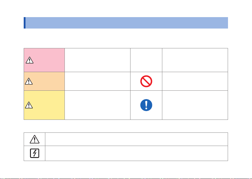
Concerning Safety
In this document, the risk seriousness and the hazard levels are classied as follows.
DANGER
WARNING
CAUTION
Indicates an imminently
hazardous situation that will
result in death or serious injury to
the operator.
Indicates a potentially hazardous
situation that may result in death
or serious injury to the operator.
Indicates a potentially hazardous
situation that may result in minor
or moderate injury to the operator
or damage to the instrument or
malfunction.
IMPORTANT
Indicates information related to
the operation of the instrument or
maintenance tasks with which the
operators must be fully familiar.
Indicates prohibited actions.
Indicates an action that must be
performed.
Symbols Afxed to the Instrument
Indicates cautions and hazards. Refer to the “Usage Notes” (p. 6) section of the instruction
manual and the included “Operating Precautions” for more information.
Indicates that the instrument may be connected to or disconnected from a live conductor.
2
Page 7
Notations
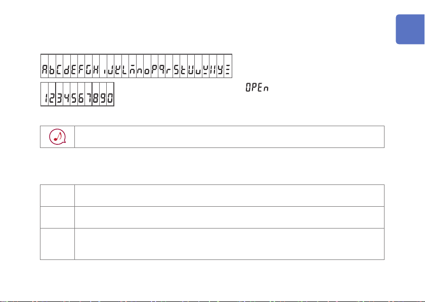
Screen display
The instrument screen displays the alphanumeric characters as follows.
A B C D E F G H I J K L M N O P Q R S T U V W X Y Z
A different display is used in the case
below.
1 2 3 4 5 6 7 8 9 0
: Wiring break detected
Other
Indicates a buzzer sound (either intermittent or continuous).
Accuracy
We dene measurement tolerances in terms of f.s. (full scale), rdg. (reading) and dgt. (digit) values with the
following meanings:
f.s. (maximum display value/range)
The maximum displayable value. This is usually the name of the currently selected range.
rdg. (displayed value)
The value currently being measured and displayed on the measuring instrument.
dgt. (resolution)
The smallest displayable unit on a digital measuring instrument, i.e., the input value that causes
the digital display to show a “1” as the least-signicant digit.
3
Page 8
Verifying Package Contents
L4937 マグネットアダプ
タ
L4934 小ワニグチ
マグネ付ストラップ
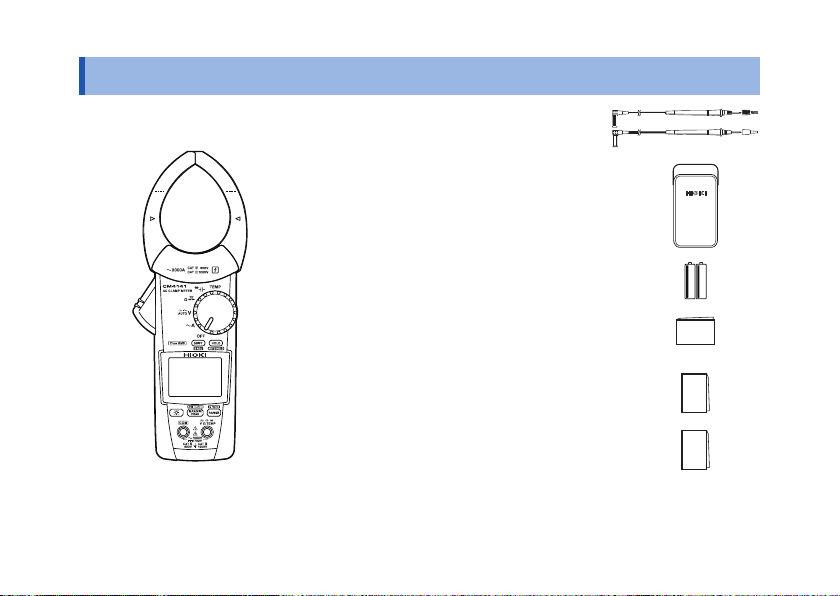
Verifying Package Contents
Model CM4141 or CM4142
AC Clamp Meter
Model L9207-10 Test Lead
Model C0203 Carrying Case
LR03 Alkaline battery ×2
Instruction Manual*
Operating Precautions (0990A907)
Precautions Concerning Use of
Equipment that Emits Radio Waves (only
for model CM4142)
* Instruction manuals may also be available in other languages.
Please visit our website at http://www.hioki.com
4
Page 9
Options (sold separately)
9243 graber
L4937 マグネットアダプ
タ
L4934 小ワニグチ
マグネ付ストラップ
DM4910 熱電対
DT4911TestLead
DT4912TestLead
L4930 接続ケーブル
9243 graber
L4937 マグネットアダプ
タ
L4934 小ワニグチ
マグネ付ストラップ
L9207-10
DM4910 熱電対
DT4911TestLead
DT4912TestLead
L4930 接続ケーブル
L4931renketu
9243 graber
L4937 マグネットアダプ
タ
L4934 小ワニグチ
マグネ付ストラップ
L9207-10
DM4910 熱電対
DT4911TestLead
DT4912TestLead
L4930 接続ケーブル
L4931renketu
L4931 延長ケーブル
L4932(+9207-10cap)
L4933 コンタクトピン
L4935 ワニ口
9243 graber
L4937 マグネットアダプ
9243 graber
L4937 マグネットアダプ
タ
L4934 小ワニグチ
マグネ付ストラップ
L9207-10
DM4910 熱電対
DT4911TestLead
DT4912TestLead
L4930 接続ケーブル
L4931renketu
L4931 延長ケーブル
L4932(+9207-10cap)
L4933 コンタクトピン
L4935 ワニ口
L4936 バスバー
L4937 マグネットアダプ
タ
9243 graber
L4937 マグネットアダプ
タ
L4934 小ワニグチ
マグネ付ストラップ
L9207-10
DM4910 熱電対
DT4911TestLead
DT4912TestLead
L4930 接続ケーブル
L4931renketu
L4931 延長ケーブル
L4932(+9207-10cap)
9243 graber
L4937 マグネットアダプ
タ
L4934 小ワニグチ
マグネ付ストラップ
L9207-10
DM4910 熱電対
DT4911TestLead
DT4912TestLead
L4930 接続ケーブル
L4931renketu
L4931 延長ケーブル
L4932(+9207-10cap)
L4933 コンタクトピン
L4937 マグネットアダプ
タ
L4934 小ワニグチ
L4937 マグネットアダプ
タ
L4934 小ワニグチ
マグネ付ストラップ
9243 graber
L4937 マグネットアダプ
タ
DM4910 熱電対
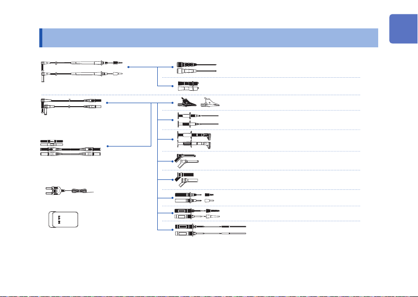
Options (sold separately)
L9207-10 Test Lead
L4930 Connection Cable Set
(Length: 1.2 m)
L4931 Extension Cable Set *
(Length: 1.5 m, with the coupling
connector)
DT4910 Thermocouples (K)
C0203 Carrying Case
*1: CAT IV 600 V/ CAT III 1000 V/ CAT II 1000 V *5: CAT III 300 V/ CAT II 600 V
*2: CAT IV 600 V/ CAT III 1000 V *6: 33 V AC/ 70 V DC
*3: CAT III 1000 V *7: CAT III 600 V/ CAT II 600 V
*4: CAT III 600 V *8: CAT IV 1000 V
1
*
2
*
2
L4933 Contact Pin Set
L4934 Small Alligator Clip Set
L4935 Alligator Clip Set
9243 Grabber Clip
L4936 Bus Bar Clip Set
L4937 Magnetic Adapter Set
9804 Magnetic Adapter *
L4932 Test Pin Set
L4938 Test Pin Set
L4939 Breaker Pin Set
6
*
2
*
3
*
4
*
8
1
*
7
*
5
*
3
*
4
*
5
Page 10
Usage Notes
Usage Notes
Follow these precautions to ensure safe operation and to obtain the full benets of the various
functions. Read the separate document “Operating Precautions” carefully before using the
instrument. Ensure that your use of the product falls within the specications not only of the
instrument itself, but also of any accessories, options, batteries, and other equipment being
used.
DANGER
• To prevent an electric shock, do not touch any areas beyond the barrier
while the instrument is in use.
See: “Part Names” (p. 12)
• The maximum measurement current varies with the frequency, and the
current that can be measured continuously is limited. Operating the
instrument at less than this limitation is referred to as derating. Do not
measure currents in excess of the derating curve. Doing so may result in
instrument damage or malfunction, a re, or burn due to sensor heating.
• Never apply a voltage to the instrument when the resistance, continuity
check, diode check, capacitance, or temperature functions are selected.
Damage to the instrument can cause bodily injury. To avoid electrical
accidents, turn off the circuit before measuring it.
6
Page 11
Usage Notes
DANGER
• To prevent an electric shock, conrm that the white portion (insulation layer)
inside the cable is not exposed. If a color inside the cable is exposed, do not
use the cable.
WARNING
Do not allow the instrument to get wet, and do not take measurements with wet
hands. This may cause an electric shock. (This precaution does not apply to
insulated conductors.)
To prevent an electric shock, do not exceed the lower of the ratings shown on
the instrument and test leads.
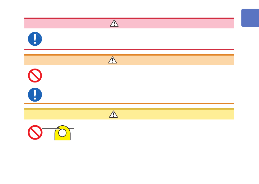
CAUTION
Do not place any foreign object between the jaws or any insert foreign
object into the gap of the sensor head. Doing so may worsen the
performance of the sensor or the opening-closing operation of the
sensor head.
7
Page 12
Usage Notes
8
CAUTION
Avoid dropping or jarring the instrument, which could damage the jaw,
adversely affecting measurement.
IMPORTANT
Clamp the instrument around only one conductor. The instrument will
not be able to make a measurement if you clamp it around two or
more wires together, regardless of whether they are part of a singlephase or three-phase circuit.
Page 13
Test Lead
Usage Notes
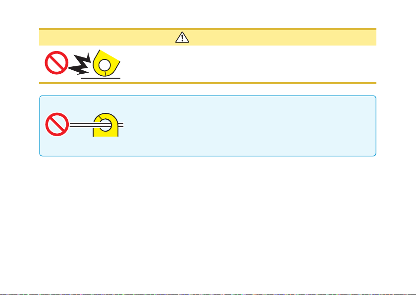
WARNING
To prevent an electric shock, when measuring the voltage of a power line use a
test lead that satises the following criteria:
• Conforms to safety standards IEC61010 or EN61010
• Measurement category III or IV
• Its rated voltage is higher than the voltage to be measured
The optional test leads provided for the instrument conform to the safety
standard EN61010. Use a test lead in accordance with its dened measurement
category and rated voltage.
• To prevent a short-circuit accident, be sure to use the test leads with the
sleeves attached when performing measurements in the CAT III and CAT IV
measurement categories.
• If the sleeves are removed during measurement, stop the measurement.
CAUTION
The cable is hardened in freezing temperatures. Do not bend or pull it to avoid tearing
its shield or cutting cable.
9
Page 14
Usage Notes
Model L4937, 9804 Magnetic Adapter Set (optional)
DANGER
P
ersons wearing electronic medical devices such as a pacemaker should not
use the Magnetic Adapter Set. Such persons should avoid even proximity to the
Magnetic Adapter Set, as it may be dangerous. Medical device operation could be
compromised, presenting a hazard to human life.
CAUTION
• Do not subject the Magnetic Adapter Set to mechanical shock, for example, due to
dropping it. Shock can cause it to be chipped or cracked.
• Do not use the Magnetic Adapter Set in locations where it may be exposed to
rainwater, dust, or condensation. In those conditions, the Magnetic Adapter Set
may be decomposed or deteriorated. The magnet adhesion may be diminished. In
such case, the instrument may not be hung in place and may fall.
• Do not bring the Magnetic Adapter Set near magnetic storage device such as
oppy disks, magnetic cards, pre-paid cards, or magnetized tickets. Doing so may
corrupt and may render them unusable. Furthermore, if the Magnetic Adapter
Set is brought near precision electronic equipment such as PCs, TV screens, or
electronic wrist watches, they may fail.
10
Page 15
1
Overview
1.1 Product Overview and Features
This instrument is a clamp meter that can
perform true RMS measurement of current
simply by clamping it around a circuit. In
addition to current, it provides voltage
measurement, frequency measurement, rush
current measurement, resistance measurement,
diode measurement, capacitance measurement,
and temperature measurement.
Model CM4142 also provide Bluetooth®
communications functionality, allowing
measurement data to be monitored and logged
from a mobile device.
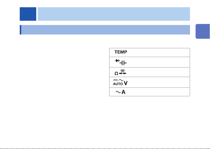
Measurement function list
1
Temperature
Capacitance, diode
Continuity check, resistance
AUTO V, AC voltage, DC voltage,
AC+DC voltage
AC current
11
Page 16

Overview
1.2 Part Names
Front Rear
1
2
3
(CM4141)
12
1 Operation grip
2 Jaw open/closed mark
(The jaws are open if the mark is not
4
5
6
7
8
9
10
11
12
showing.)
3 SHIFT key
(Selects function indicated in blue lettering.)
4 Jaw (p. 14)
5 Barrier
6 Serial number (The serial number consists of
9 digits. The rst two (from the left) indicate
the year of manufacture, and the next two
indicate the month of manufacture.)
7 Rotary switch
8 HOLD key
9 LCD
10 Battery cover
11 Operation keys
12 Measurement terminals
Page 17
2
NO
NONO
Making Measurements
2.1 Inspection Before Measurement
Check if there is any damage to the instrument occurred during storage or shipping and
verify that instrument operates normally before using it. If you nd any damage, contact your
authorized Hioki distributor or reseller.
Check item
The battery cover is closed and its screw has
been securely tightened.
There is no damage to the test lead
insulation, and neither the white sheathing nor
metal conductor inside the wire are exposed.
2
There is no foreign matter on the
measurement terminals. (p. 12)
The test leads are not broken.
1 Ω or less
OK
The instrument is neither damaged nor cracked.
No indicators are missing.
(All lit up)
13
Page 18
Current Measurement
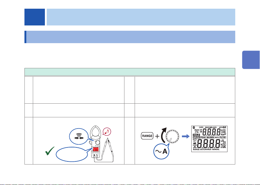
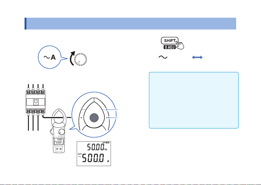
2.2 Current Measurement
1
Turn the rotary switch.
2
Clamp the instrument around a conductor.
e.g.: 3P4W (3-phase, 4-wire) circuit
breaker (AC current measurement)
14
3
Hz
+
(AC A)
(Frequency)Hz(Frequency)
Frequency detection range of AC current
3 A or more (60.00 A range)
30 A or more (600.0 A range)
200 A or more (2000 A range)
Area mark
Jaw center
(maximum
precision)
Maximize measurement precision by positioning the wire on the
center side of the area mark.
Range (p. 18)
Default setting is auto range.
Press the RANGE key to switch to manual
range.
Page 19
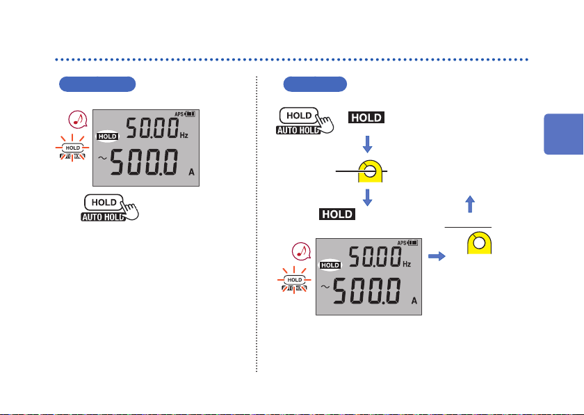
Manual Hold / Auto Hold
Manual hold Auto hold
Press for 1 sec.
Blinks
Measured value
retains.
Pressing the HOLD key again cancels
the measured value hold function.
measured value stabilizes.)
Blinks
Measured value automatically retains.
Pressing the HOLD key for 1 sec. cancels the auto
hold function.
(
lights up when
Current Measurement
blinks.
2
Clamp the instrument around a
conductor.
Disconnect
15
Page 20
Current Measurement
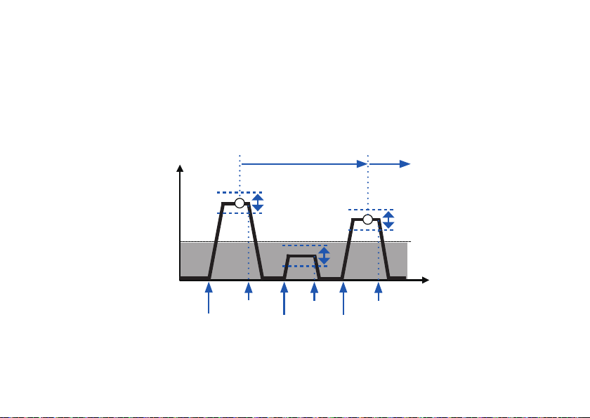
Auto hold conditions
Display value updates are stopped when the following two conditions are satised:
• When the measured value exceeds the threshold value described in the table in the next page. (voltage,
current). When the measured value is less than the threshold value described in the table in the next page.
(resistance, continuity, diode)
• When the range over which the measured value is uctuating stabilizes within the uctuation range
described in the table in the next page.
Held measured value
Measured
value
Auto hold
e.g.: 100.0 A
Fluctuation range
Fluctuation range
Auto hold
e.g.: 99.0 A
Fluctuation range
Threshold
e.g.: 12.0 A
Start
End
If the measured value falls below the threshold value (voltage, current) or exceeds the threshold value
(resistance, continuity, diode) after display value updates are stopped, the display value update is restarted.
Display value updates will stop if the two conditions are satised once again.
End
Start
Measurement
End
Start
Time
16
Page 21

Current Measurement
Measurement function Fluctuation range Threshold value
AC current 60.00 A range: within 400 counts
AUTO V
AC voltage
DC voltage
AC+DC voltage
Resistance
Continuity
Diode 1.800 V range: within 40 counts 1.800 V range: 1460 counts
The auto hold function only operates for the above measurement functions.
600.0 A range: within 400 counts
2000 A A range: within 40 counts
6.000 V/60.00 V/600.0 V range:
within 120 within
1000 V range: within 20 counts
1500 V range: within 30 counts
/6.000 kΩ/60.00 kΩ/
600.0
Ω
range: within 100 counts
600.0 k
Ω
60.00 A range: 100 counts
600.0 A range: 120 counts
2000 A range: 40 counts
6.000 V/60.00 V/600.0 Vrange:
120 counts
1000 V range: 20 counts
1500 V range: 30 counts
600.0
/6.000 kΩ/60.00 kΩ/
Ω
range: 4900 counts
600.0 k
Ω
2
17
Page 22
Current Measurement
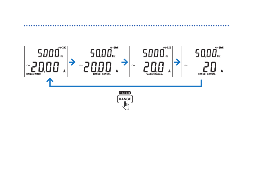
Switching the range
Auto range
(default setting)
18
Manual
60.00 A range
Manual
600.0 A range
Manual
2000 A range
Page 23
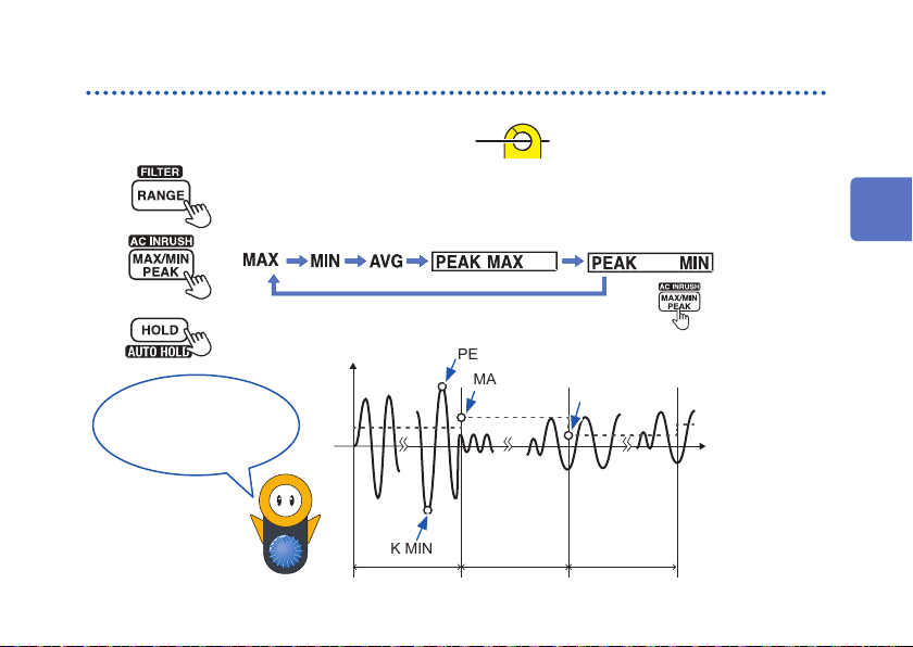
MAX value/MIN value/AVG value/PEAK value
1
Clamp the instrument around a conductor.
Current Measurement
2
3
4
The instrument
performs true RMS
measurement.
“AVG” indicates
the average of all
measured values.
See: “Switching the range” (p. 18)
In auto-range mode, the instrument will be automatically set to the 2000 A range.
Press for 1 sec.
Measured value retains.
PEAK MIN
PEAK MAX
MAX
MIN
Waveform
Measured value
(RMS value)
Display refresh interval
Cancel
2
19
Page 24

Current Measurement
Filter Function
FILTER OFF FILTER ON
Measured value including noise
Press for 1 sec.
Measured value with reduced noise
Frequency characteristics when using the
lter function (100 A input)
FILTER OFF
FILTER ON Passband 100 [Hz]
Measured value [A]
Frequency [Hz]
20
Turn off the lter function when performing
measurement of power supply frequencies in excess
of 100 Hz, for example on an aircraft or ship.
Filter OFF
Page 25

Rush current (AC INRUSH)
Current Measurement
1
Turn off the motor.
Turn the rotary switch.
2
Clamp the instrument around a
3
conductor.
4
Set the range.
Load side
Current direction
Power supply side
See: “Switching the range” (p. 18)
In auto-range mode, the
instrument will be automatically
set to the 2000 A range.
5
Press for 1 sec.
AC INRUSH ON
6
Turn on the motor.
The instrument can measure
AC rush current. Rush current
containing a DC component cannot
be measured accurately.
RMS value (INRUSH)
Example
screen: 100 A
AC current
Example screen: 250 A
Maximum wave height (PEAK)
Interval during which rush current occurs
(Dozens to hundreds of milliseconds in duration)
(Rush current
occurrence)
Trigger level
±2 A peak (60.00 A range)
±10 A peak (600.0 A range)
±100 A peak (2000 A range)
2
21
Page 26

Other Measurement Functions
2.3 Other Measurement Functions
Voltage
e.g.: commercial power supply (AC voltage measurement)
2 3
Switch the range
22
1
NO
(Red ash)
Do not touch.No overvoltage
Red Black
NO
AUTO
DC voltage polarity detection function (p. 27)
If the measured value is negative, the buzzer will sound,
and the display will turn red (threshold: −10 V).
Hz
(AUTO AC/DC)
(AC V)
(DC V)
(AC+DC V)
(Frequency)
Page 27

Other Measurement Functions
Continuity Check
Zero adjustment
1
Red
(Red display)
Press for 1 sec.
2
Black
Resistance
1
Red
Zero adjustment
Press for 1 sec.
2
Black
2
23
Page 28

Other Measurement Functions
24
Capacitance
Red
Black
Diode
BlackRed
Buzzer sound
Intermittent sound: during forward connection (0.15 V to 1.8 V),
backlight off
Continuous sound: during forward connection (less than 0.15 V),
red backlight on
Page 29

Other Measurement Functions
Temperature
−
+
Black Red
IMPORTANT
Thermocouples (K) experience a phenomenon known
as short-range ordering that may prevent accurate
measurement in the range of 250°C to 600°C.
To change the temperature display unit: p. 28
Model DT4910
Thermocouples (K)
: DT4910 is broken.
2
25
Page 30

Backlight / Auto Power Save (APS)
2.4 Backlight / Auto Power Save (APS)
Backlight Auto Power Save (APS)
Backlight OFF
Backlight ON
Automatically switched off when the
instrument is not in use for 40 sec.
(Automatic backlight deactivation ON)
Cancelation method: p. 27
The instrument is automatically turned off.
To restart the instrument, briey set the rotary switch to “OFF.”
26
(Always on)
Cancelation method: p. 27
No operation
for 15 min.
You can turn the display back on
by pressing a key or by turning the
rotary switch.
No operation for 45 min.
Page 31

2.5 Power-on Option Table
Power-on Option Table
+
Canceling the auto power save (APS)
function (OFF)
DC voltage polarity detection function
(ON/OFF)
Displaying all indicators
(Version of software/Model number/
Serial number)
Buzzer sound (ON/OFF)
Automatic backlight deactivation
(ON/OFF)
Move the rotary switch from the “OFF” position to any of the test mode positions
while pressing an operation key.
Setting Operating instruction
Factory
setting
ON
OFF Yes
– –
ON Yes
ON Yes
retained?
(Set each time)
Setting
2
No
27
Page 32

Power-on Option Table
Setting Operating instruction
Switching the temperature unit
28
Press for 1 sec.
To change the
temperature unit:
To save the setting:
Press for 1 sec.
Factory
setting
°C Yes
Setting
retained?
Page 33

Bluetooth® Communications (only for model CM4142)
2.6 Bluetooth® Communications (only for model CM4142)
The CM4142 supports Bluetooth (Bluetooth low energy). When the Bluetooth function is enabled, you can
review measurement data and create measurement reports on mobile devices (iPhone, iPad, iPad mini
iPad Pro, iPod touch, and Android
function in the application software GENNECT Cross.
Install the GENNECT Cross on your mobile device. (p. 30)
1
Enable the Bluetooth function on the CM4142. (p. 31)
2
Launch the GENNECT Cross and pair it with the CM4142. (p. 32)
3
Select the General Measurement, Logging (Recording), or
4
Waveform/FFT function. (p. 33)
TM
devices). For more information about this functionality, see the Help
Press for 1 sec.
TM
,
2
29
Page 34

Bluetooth® Communications (only for model CM4142)
Installing the application software GENNECT Cross
Search for “GENNECT Cross” on the App Store from your iPhone, iPad or other Apple device, or on Google
TM
from your Android device. Then download and install the GENNECT Cross. You will need an Apple ID
Play
to download the app on the App Store, or a Google account to download the app on Google Play. For more
information about how to register an account, contact the store at which you purchased your device.
• Because the CM4142 emit radio waves, use in a country or region where they have not been approved may
be subject to nes or other penalties as a violation of applicable laws or regulations. For more information,
see the attached “Precautions Concerning Use of Equipment that Emits Radio Waves” or go to our website.
• The CM4142 availability is limited to certain countries. For more information, contact your authorized Hioki
distributor or reseller.
• The distance over which data can be sent and received using Bluetooth varies greatly depending on
whether there are any obstructions between the paired instruments (for example, walls, metal barriers, etc.)
and on the distance between the instrument and the oor (or ground). To ensure stable measurement, verify
adequate signal strength.
• Although this application software is provided free of charge, downloading or using the application software
may incur Internet connection charges. Such charges are the sole responsibility of the user.
• This application software is not guaranteed to operate on all mobile devices.
30
Page 35

Bluetooth® Communications (only for model CM4142)
Turning on the Bluetooth function
Bluetooth function OFF Bluetooth function ON
2
Press for 1 sec.
lights up: Bluetooth function ON
ashes: Sending/receiving data
31
Page 36

Bluetooth® Communications (only for model CM4142)
Pairing the app with the CM4142
• When the app is launched for the rst time (before being paired with any instrument), the Instrument
Settings screen will be displayed.
• While the mobile device is displaying the Instrument Settings screen, simply move it close to a CM4142 to
automatically pair it with the instrument (the app can be paired with up to 8 instruments).
• Allow about 5 to 30 seconds for the CM4142 to pair with the app after being turned on. If the instrument fails
to pair within 1 minute, relaunch GENNECT Cross and cycle the instrument’s power.
32
Page 37

Bluetooth® Communications (only for model CM4142)
Making measurements with the Bluetooth function
Select the General Measurement, Logging (Recording), or Waveform/FFT function on the Home screen.
For more information about each function, see the Help function in the GENNECT Cross.
2
General Measurement
Saves measured values from
multiple channels
Logging (Recording)
Simple logging (up to 24 hours)
Waveform/FFT
Simple oscilloscope
(voltage/current)
33
Page 38

Bluetooth® Communications (only for model CM4142)
34
Page 39

3
Specications
3.1 General Specications
Operating environment Indoors, pollution degree 2, altitude up to 2000 m (6562 ft.)
Operating temperature
and humidity
Storage temperature
and humidity
Dustproof and
waterproof
Standards Safety EN 61010
Power supply LR03 alkaline battery ×2
Continuous operating
time
−25°C to 65°C (−13°F to 149°F), 90% RH or less (no condensation)
−30°C to 70°C (−22°F to 158°F), 90% RH or less
(no condensation, when batteries are removed)
IP20 (Measuring voltage or current in a hazardous live conductor while
completely dry)
IP50 (Measuring resistance or current in an insulated conductor while completely
dry, or during storage)
However, the instrument’s handle provides IP54-equivalent dust and water
protection when the instrument is not making a measurement.
EMC EN 61326
Rated supply voltage: 1.5 V DC ×2
Approx. 48 hours (Bluetooth communication OFF)
Approx. 24 hours (Bluetooth communication ON)
Other conditions: 100 A AC measurement, LCD backlight OFF, at 23°C (73.4°F),
for reference
3
35
Page 40

General Specications
Interface (only for
CM4142)
Dimensions Approx. 65W × 247H × 35D mm (2.56″W × 9.72″H × 1.38″D) (excluding
Jaw dimensions Approx. 82W × 11D mm (3.23″W × 0.43″D) (The D gure indicates the depth for
Jaw cross-sectional
minimum dimension
Maximum measurable
conductor diameter
Mass Approx. 300 g (10.6 oz.) (including batteries)
Product warranty
period
Accessories See: “Verifying Package Contents” (p. 4)
Options See: “Options (sold separately)” (p. 5)
Bluetooth 4.0 LE
protruding parts, operation grip, and jaw)
the rst 44 mm of each jaw from its tip.)
Approx. 11 mm (0.43″) (Indicates the depth for the rst 44 mm of each jaw from
its tip.)
55 mm (2.17″)
φ
3 years
Number of jaw open/close cycles: 30,000
(p. 29)
36
Page 41

Input specications/Measurement specications
3.2 Input specications/Measurement specications
(1) Basic Specications
Measurement range See “3.3 Accuracy Table” (p. 44)
Maximum input current As per frequency derating (p. 38)
Maximum input voltage to terminal 600 V AC (Measurement category IV)
to earth 600 V AC (Measurement category IV)
Measurement method True RMS measurement
Measurement terminals COM terminal and V terminal
Coupling type AC current/current frequency/
AC INRUSH/AC voltage*
voltage frequency
Measurement items other than the
above
1
/
1000 V AC (Measurement category III)
1000 V AC (up to 1 kHz)
1700 V DC
1000 V AC (Measurement category III)
Anticipated transient overvoltage: 8000 V
AC coupling
DC coupling
3
37
Page 42

Input specications/Measurement specications
Display update rate *2AC current/AUTO V/AC voltage/
DC voltage/AC+DC voltage
Current frequency/
voltage frequency/capacitance
Temperature (Thermocouples [K]) 1 time/sec.
*1: Does not apply to AC detection in AUTO V mode or to the AC component when DC+AC voltage are mixed.
*2: Does not include range change time.
5 times/sec.
0.5 times to 5 times/sec. (varies depending
on the measurement value.)
(2) Current measurement specications
Frequency derating Lower of 3000 A AC or 6×10⁶ A · H z
Zero-display range AC current
Crest factor AC current/
Frequency detection
input level
(continuous, design value)
5 counts or less
AC INRUSH
AC current/
current frequency
60.00 A range
600.0 A range
2000 A range 1.5 (2000 counts or less)
60.00 A range
600.0 A range
2000 A range 200 counts or more
3 (5000 counts or less)
2.5 (more than 5000 counts,
6000 counts or less)
300 counts or more
38
Page 43

AC INRUSH
Trigger level
Peak detection time
width
AC INRUSH
AC current/
AC INRUSH
Input specications/Measurement specications
60.00 A range
600.0 A range
2000 A range
+2.0 A
or 2.0 A
+10 A
or 10 A
+100 A
or 100 A
1 ms or more (when lter is off)
PEAK
PEAK
PEAK
PEAK
or more,
or less
PEAK
or more,
or less
or more,
or less
PEAK
(3) Voltage measurement specications
Overload protection 1870 V DC
Lower of 1100 V AC or 2×10
(Applied continuously for up to 1 min.)
Input impedance See “3.3 Accuracy Table” (p. 44)
Zero-display range AUTO V/AC voltage/
AC+DC voltage
Crest factor AUTO V/AC voltage/
AC+DC voltage
7
V · Hz
5 counts or less
6.000 V range
60.00 V range
600.0 V range
1000 V range 2 (850 counts or less)
3
3 (4000 counts or less)
2 (more than 4000 counts, 6000
counts or less)
1.7 (more than 850 counts, 1000
counts or less)
39
Page 44

Input specications/Measurement specications
Frequency detection
input level
1
CMRR *
2
NMRR *
Peak detection time
width
*1: Dened for 1 k
*2: Dened for 50 Hz/60 Hz input
AUTO V/AC voltage 10% or more of each range f.s.
AC voltage/AC+DC
voltage
DC voltage −100 dB or more
DC voltage −60 dB or more
AC voltage 1 ms or more (when lter is off)
unbalance, 0 Hz/50 Hz/60 Hz input
Ω
−60 dB or more
(4) Other Measurement Specications
Overload
protection
Overload current At steady state: 30 mA or less
Measurement
current/charging
current
1700 V DC
Lower of 1000 V AC or 2×10
(Applied continuously for up to 1 min.)
At transient state: 1.5 A or less
See “3.3 Accuracy Table” (p. 44)
7
V · Hz
40
Page 45

Open terminal
voltage
Continuity on
threshold
Continuity off
threshold
Maximum capacity
load
Maximum inductive
load
Instrument
reference contact
temperature
correction
stabilization time
2.0 V DC or less
Continuity check 25
Continuity check 245
Resistance 10 mF
Resistance 10 H
Temperature
(Thermocouples [K])
Ω
lights up)
Up to 120 minutes (Reference: For an instrument at 23°C
[ 73°F ] placed in a 65°C [ 149°F ] environment: 60 minutes)
Input specications/Measurement specications
±10 Ω (continuous buzzer sound, red warning backlight
±10
Ω
Ω
3
41
Page 46

Input specications/Measurement specications
(5) Accuracy specications
Conditions of
guaranteed
accuracy
Conditions of
accuracy input
Measurement
accuracy
Temperature
coefcient
Guaranteed accuracy
period
Guaranteed accuracy
period after adjustment
made by Hioki
Guaranteed accuracy for
temperature and humidity
Continuity check/resistance: after zero adjustment has been performed
Use model DT4910 for temperature (Thermocouples [K])
Sine wave input
See “3.3 Accuracy Table” (p. 44)
Add “measurement accuracy × 0.1/°C” (excluding 23°C±5°C [ 73°F±9°F ]).
1 year (accuracy shown in accuracy table)
3 years (accuracy shown in accuracy table × 1.5)
(reference values)
1 year
23°C±5°C (73°F±9°F), 90% RH or less (no condensation)
42
Page 47

Input specications/Measurement specications
Effects of conductor
position *
Effect of radiated
radio-frequency
electromagnetic
eld
*1: At 100 A, 55 Hz measurements around the jaw’s center-point reference
1
Cable diameter
2
CV8 mm
(Finished outer diameter:
8.6 mm)
CV38 mm
(Finished outer diameter:
13 mm)
Add ±2% rdg. at 10 V/m.
2
Measurement
area
Area A Within ±3.0% rdg.
Area B Within ±7.0% rdg.
Area A Within ±2.0% rdg.
Area B Within ±5.0% rdg.
Accuracy
Measurement
area gure
B
A
3
43
Page 48

Accuracy Table
3.3 Accuracy Table
(1) AC current
Measurement value/MAX/MIN/AVE (rms)
Range
(Auto-range threshold)
60.00 A
(more than 6000 counts)
600.0 A
(more than 6000 counts/
less than 540 counts)
2000 A
(less than 540 counts)
*1: Accuracy not dened beyond 66 Hz.
*2: Design values apply beyond 6×10
Accuracy
guarantee range
(Resolution)
1.00 A to 60.00 A
(0.01 A)
1.0 A to 600.0 A
(0.1 A)
10 A to 2000 A
(1 A)
5
A · Hz.
Accuracy
guarantee
frequency range
45 Hz ≤ f ≤ 66 Hz ±1.5% rdg.±0.08 A ±2.0% rdg.±0.08 A
30 Hz ≤ f < 45 Hz,
66 Hz < f ≤ 1 kHz
45 Hz ≤ f ≤ 66 Hz ±1.5% rdg.±0.3 A ±2.0% rdg.±0.3 A
30 Hz ≤ f < 45 Hz,
66 Hz<f ≤ 1 kHz
45 Hz ≤ f ≤ 66 Hz ±1.5% rdg.±3 A ±2.0% rdg.±3 A
30 Hz ≤ f < 45 Hz,
66 Hz<f ≤ 1 kHz*
44
Measurement accuracy
Filter OFF Filter ON*
±2.0% rdg.±0.10 A ±2.5% rdg.±0.10 A
±2.0% rdg.±0.5 A ±2.5% rdg.±0.5 A
±2.0% rdg.±5 A ±2.5% rdg.±5 A
2
1
Page 49

PEAK MAX/PEAK MIN (Zero to Peak)
Range
60.00 A ±1.0 A to ±150.0 A
600.0 A ±10 A to ±1500 A
2000 A ±10 A to ±2840 A
Accuracy guarantee range
(Resolution)
(0.1 A)
(1 A)
(1 A)
(2) Current frequency
Range
(Auto-range threshold)
99.99 Hz
(more than 9999 counts)
999.9 Hz
(less than 900 counts)
*1: Add ±0.2 Hz if less than 100.0 Hz.
Accuracy guarantee range
30.00 Hz to 99.99 Hz (0.01 Hz) ±0.1% rdg.±0.01 Hz
30.0 Hz to 999.9 Hz (0.1 Hz) ±0.1% rdg.±0.1 Hz*
Accuracy
guarantee
frequency range
45 Hz ≤ f ≤ 66 Hz ±1.5% rdg.±0.8 A
30 Hz ≤ f < 45 Hz,
66 Hz < f ≤ 1 kHz
45 Hz ≤ f ≤ 66 Hz ±1.5% rdg.±3 A
30 Hz ≤ f < 45 Hz,
66 Hz < f ≤ 1 kHz
45 Hz ≤ f ≤ 66 Hz ±1.5% rdg.±30 A
30 Hz ≤ f < 45 Hz,
66 Hz < f ≤ 1 kHz
(Resolution)
Measurement accuracy
±2.0% rdg.±1.0 A
±2.0% rdg.±5 A
±2.0% rdg.±50 A
Measurement accuracy
Accuracy Table
3
1
45
Page 50

Accuracy Table
(3) AC INRUSH (Rush current)
AC INRUSH measurement value (rms)
Range
60.00 A 3.00 A to 60.00 A
600.0 A 10.0 A to 600.0 A
2000 A 100 A to 2000 A
*1: Design values apply beyond 6×10
Accuracy guarantee range
(Resolution)
(0.01 A)
(0.1 A)
(1 A)
5
A · Hz.
AC INRUSH PEAK value (Zero to Peak)
Range
60.00 A 3.0 A to 150.0 A
600.0 A 10 A to 1500 A
2000 A 100 A to 2840 A
Accuracy guarantee range
(Resolution)
(0.1 A)
(1 A)
(10 A)
46
Accuracy guarantee
frequency range
40 Hz ≤ f ≤ 500 Hz ±5.0% rdg.±0.13 A
40 Hz ≤ f ≤ 500 Hz ±5.0% rdg.±1.3 A
40 Hz ≤ f ≤ 500 Hz*
Accuracy guarantee
frequency range
40 Hz ≤ f ≤ 500 Hz ±5.0% rdg.±1.0 A
40 Hz ≤ f ≤ 500 Hz ±5.0% rdg.±10 A
40 Hz ≤ f ≤ 500 Hz ±5.0% rdg.±100 A
Measurement accuracy
1
±5.0% rdg.±13 A
Measurement accuracy
Page 51

Accuracy Table
(4) AUTO V (AC/DC voltage automatic detection)
During AC detection: Conforms to accuracy specications described in “(7) AC+DC voltage” (p. 52).
During DC detection: Conforms to accuracy specications described in “(6) DC voltage” (p. 50).
(5) AC voltage
Measurement value/MAX/MIN/AVE
Range
(Auto-range
threshold)
6.000 V (more
than 6000
counts)
Accuracy
guarantee range
(Resolution)
0.000 V to 0.299
V (0.001 V)
0.300 V to 6.000
V (0.001 V)
Accuracy guarantee
frequency range *
15 Hz ≤ f < 45 Hz ±1.5% rdg.
45 Hz ≤ f ≤ 66 Hz ±0.9% rdg.
66 Hz < f ≤ 1 kHz ±1.5% rdg.
15 Hz ≤ f < 45 Hz ±1.5% rdg.
45 Hz ≤ f ≤ 66 Hz ±0.9% rdg.
66 Hz < f ≤ 1 kHz ±1.5% rdg.
Measurement accuracy
1 *2
Filter OFF Filter ON
±0.015 V
±0.013 V
±0.015 V
±0.005 V
±0.003 V
±0.005 V
±2.0% rdg.
±0.015 V
±1.4% rdg.
±0.013 V
–
±2.0% rdg.
±0.005 V
±1.4% rdg.
±0.003 V
–
impedance *
3.2 M
3.2 M
Input
±5%
Ω
±5%
Ω
3
3
47
Page 52

Accuracy Table
Range
(Auto-range
threshold)
60.00 V
(more than
6000 counts/
less than 540
counts)
600.0 V
(more than
6000 counts/
less than 540
counts)
1000 V
(less than 540
counts)
*1: Frequency range of 15 Hz ≤ f < 20 Hz is designed value.
*2: Within the frequency range of f < 45 Hz, the accuracy guarantee assumes a superposed DC voltage of
less than 500 V.
*3: At 50 Hz AC.
Accuracy
guarantee range
(Resolution)
3.00 V to 60.00 V
(0.01 V)
30.0 V to 600.0 V
(0.1 V)
50 V to 1000 V
(1 V)
Accuracy guarantee
frequency range *
15 Hz ≤ f < 45 Hz ±1.5% rdg.
45 Hz ≤ f ≤ 66 Hz ±0.9% rdg.
66 Hz < f ≤ 1 kHz ±1.5% rdg.
15 Hz ≤ f < 45 Hz ±1.5% rdg.
45 Hz ≤ f ≤ 66 Hz ±0.9% rdg.
66 Hz < f ≤ 1 kHz ±1.5% rdg.
15 Hz ≤ f < 45 Hz ±1.5% rdg.
45 Hz ≤ f ≤ 66 Hz ±0.9% rdg.
66 Hz < f ≤ 1 kHz ±1.5% rdg.
Measurement accuracy
1 *2
Filter OFF Filter ON
±0.05 V
±0.03 V
±0.05 V
±0.5 V
±0.3 V
±0.5 V
±5 V
±3 V
±5 V
±2.0% rdg.
±0.05 V
±1.4% rdg.
±0.03 V
–
±2.0% rdg.
±0.5 V
±1.4% rdg.
±0.3 V
–
±2.0% rdg.
±5 V
±1.4% rdg.
±3 V
–
Input
impedance *
±5%
3.1 M
Ω
±5%
3.0 M
Ω
±5%
3.0 M
Ω
48
3
Page 53

Accuracy Table
PEAK MAX/PEAK MIN
Range
6.000 V 0 V to ±12.00 V (0.01 V) 15 Hz ≤ f < 45 Hz ±1.8% rdg.±0.07 V
60.00 V ±3.0 V to ±120.0 V (0.1 V) 15 Hz ≤ f < 45 Hz ±1.8% rdg.±0.7 V
600.0 V ±30 V to ±1000 V *
1000 V ±50 V to ±1000 V *
*1: Frequency range of 15 Hz ≤ f < 20 Hz is designed value.
*2: Within the frequency range of f < 45 Hz, the accuracy guarantee assumes a superposed DC voltage of
less than 500 V.
*3: Values of up to ±1200 V are displayed, but accuracy is not dened for display values in excess of 1000 V
(which are provided as reference values).
*4: Values of up to ±1700 V are displayed, but accuracy is not dened for display values in excess of 1000 V
(which are provided as reference values).
Accuracy guarantee range
(Resolution)
3
(1 V) 15 Hz ≤ f < 45 Hz ±1.8% rdg.±7 V
4
(1 V) 15 Hz ≤ f < 45 Hz ±1.8% rdg.±7 V
Accuracy guarantee
frequency range *
45 Hz ≤ f ≤ 66 Hz ±1.5% rdg.±0.07 V
66 Hz < f ≤ 1 kHz ±1.8% rdg.±0.07 V
45 Hz ≤ f ≤ 66 Hz ±1.5% rdg.±0.7 V
66 Hz < f ≤ 1 kHz ±1.8% rdg.±0.7 V
45 Hz ≤ f ≤ 66 Hz ±1.5% rdg.±7 V
66 Hz < f ≤ 1 kHz ±1.8% rdg.±7 V
45 Hz ≤ f ≤ 66 Hz ±1.5% rdg.±7 V
66 Hz < f ≤ 1 kHz ±1.8% rdg.±7 V
Measurement accuracy
1 *2
3
49
Page 54

Accuracy Table
(6) DC voltage
Measurement value/MAX/MIN/AVE
Range (Auto-range threshold)
600.0 mV
(more than 6000 counts)
6.000 V (more than 6000 counts/
less than 540 counts)
60.00 V (more than 6000 counts/
less than 540 counts)
600.0 V (more than 6000 counts/
less than 540 counts)
1500 V (less than 540 counts) 0 V to ±1000 V *
*1: At DC input
*2: In the 1500 V range, the instrument can withstand input of up to 1000 V continuously or input in excess of
1000 V for no greater than 1 minute.
Accuracy guarantee range
(Resolution)
0.0 mV to ±600.0 mV
(0.1 mV)
0.000 V to ±6.000 V
(0.001 V)
0.00 V to ±60.00 V
(0.01 V)
0.0 V to ±600.0 V
(0.1 V)
(1 V)
±1001 V to ±1700 V *
(1 V)
2
2
Measurement
accuracy
±0.5% rdg.
±0.5 mV
±0.5% rdg.
±0.003 V
±0.5% rdg.
±0.03 V
±0.5% rdg.
±0.3 V
±0.5% rdg.
±3 V
±2.0% rdg.
±5 V
Input impedance*
6.7 MΩ±5%
±5%
6.7 M
Ω
±5%
6.1 M
Ω
±5%
6.0 M
Ω
6.0 M
±5%
Ω
1
50
Page 55

Accuracy Table
PEAK MAX/PEAK MIN
Range Accuracy guarantee range (Resolution) Measurement accuracy
600.0 mV 0 mV to ±1200 mV (1 mV) ±1.0% rdg.±7 mV
6.000 V 0.00 V to ±12.00 V (0.01 V) ±1.0% rdg.±0.07 V
60.00 V 0.0 V to ±120.0 V (0.1 V) ±1.0% rdg.±0.7 V
600.0 V 0 V to ±1000 V (1 V) ±1.0% rdg.±7 V
±1001 V to ±1200 V (1 V) ±5.0% rdg.±7 V
1500 V 0 V to ±1000 V (1 V) ±1.0% rdg.±7 V
±1001 V to ±1700 V (1 V) ±5.0% rdg.±7 V
3
51
Page 56

Accuracy Table
(7) AC+DC voltage
Measurement value/MAX/MIN/AVE
Range
(Auto-range
threshold)
6.000 V (more
than 6000
counts)
60.00 V
(more than
6000 counts/
less than 540
counts)
Accuracy
guarantee range
(Resolution)
0.000 V to 0.299 V
(0.001 V)
0.300 V to 6.000 V
(0.001 V)
3.00 V to 60.00 V
(0.01 V)
Accuracy guarantee
frequency range *
10 Hz ≤ f < 45 Hz ±1.5% rdg.
DC,
45 Hz ≤ f ≤ 66 Hz
66 Hz < f ≤ 1 kHz ±1.5% rdg.
10 Hz ≤ f < 45 Hz ±1.5% rdg.
DC,
45 Hz ≤ f ≤ 66 Hz
66 Hz < f ≤ 1 kHz ±1.5% rdg.
10 Hz ≤ f < 45 Hz ±1.5% rdg.
DC,
45 Hz ≤ f ≤ 66 Hz
66 Hz < f ≤ 1 kHz ±1.5% rdg.
52
Measurement accuracy
1
Filter OFF Filter ON
±0.023 V
±1.0% rdg.
±0.023 V
±0.023 V
±0.013 V
±1.0% rdg.
±0.013 V
±0.013 V
±0.13 V
±1.0% rdg.
±0.13 V
±0.13 V
±2.0% rdg.
±0.023 V
±1.5% rdg.
±0.023 V
–
±2.0% rdg.
±0.013 V
±1.5% rdg.
±0.013 V
–
±2.0% rdg.
±0.13 V
±1.5 %rdg.
±0.13 V
–
Input
impedance *
DC: 6.7 M
AC: 3.2 M
DC: 6.7 M
AC: 3.2 M
DC: 6.1 M
AC: 3.1 M
Ω
Ω
Ω
Ω
Ω
Ω
2
±5%
±5%
±5%
±5%
±5%
±5%
Page 57

Range
(Auto-range
threshold)
600.0 V
(more than
6000 counts/
less than 540
counts)
1000 V
(less than 540
counts)
*1: Frequency range of 10 Hz ≤ f < 20 Hz is designed value.
*2: At DC input, 50 Hz AC input.
Accuracy
guarantee range
(Resolution)
30.0 V to 600.0 V
(0.1 V)
50 V to 1000 V
(1 V)
Accuracy guarantee
frequency range *
10 Hz ≤ f < 45 Hz ±1.5% rdg.
DC,
45 Hz ≤ f ≤ 66 Hz
66 Hz < f ≤ 1 kHz ±1.5% rdg.
10 Hz ≤ f < 45 Hz ±1.5 %rdg.
DC,
45 Hz ≤ f ≤ 66 Hz
66 Hz < f ≤ 1 kHz ±1.5 %rdg.
Measurement accuracy
1
Filter OFF Filter ON
±0.7 V
±1.0% rdg.
±0.7 V
±0.7 V
±7 V
±1.0 %rdg.
±7 V
±7 V
±2.0% rdg.
±0.7 V
±1.5% rdg.
±0.7 V
–
±2.0 %rdg.
±7 V
±1.5 %rdg.
±7 V
–
Accuracy Table
Input
Ω
Ω
Ω
Ω
2
±5%
±5%
±5%
±5%
impedance *
DC: 6.0 M
AC: 3.0 M
DC: 6.0 M
AC: 3.0 M
53
3
Page 58

Accuracy Table
PEAK MAX/PEAK MIN
Range
Accuracy guarantee range
(Resolution)
6.000 V 0.00 V to ±12.00 V
(0.01 V)
60.00 V ±3.0 V to ±120.0 V
(0.1 V)
2
600.0 V ±30 V to ±1000 V *
(1 V)
3
1000 V ±50 V to ±1000 V *
(1 V)
*1: Frequency range of 10 Hz ≤ f < 20 Hz is designed value.
*2: Values of up to ±1200 V are displayed, but accuracy is not dened for display values in excess of 1000 V
(which are provided as reference values).
*3: Values of up to ±1700 V are displayed, but accuracy is not dened for display values in excess of 1000 V
(which are provided as reference values).
Accuracy guarantee
frequency range *
Measurement accuracy
1
10 Hz ≤ f < 45 Hz ±1.5% rdg.±0.07 V
DC, 45 Hz ≤ f ≤ 66 Hz ±1.0% rdg.±0.07 V
66 Hz < f ≤ 1 kHz ±1.5% rdg.±0.07 V
10 Hz ≤ f < 45 Hz ±1.5% rdg.±0.7 V
DC, 45 Hz ≤ f ≤ 66 Hz ±1.0% rdg.±0.7 V
66 Hz < f ≤ 1 kHz ±1.5% rdg.±0.7 V
10 Hz ≤ f < 45 Hz ±1.5% rdg.±7 V
DC, 45 Hz ≤ f ≤ 66 Hz ±1.0% rdg.±7 V
66 Hz < f ≤ 1 kHz ±1.5% rdg.±7 V
10 Hz ≤ f < 45 Hz ±1.5% rdg.±7 V
DC, 45 Hz ≤ f ≤ 66 Hz ±1.0% rdg.±7 V
66 Hz < f ≤ 1 kHz ±1.5% rdg.±7 V
54
Page 59

Accuracy Table
(8) Voltage frequency
Range
(Auto-range threshold)
9.999 Hz
(more than 9999 counts
99.99 Hz
(more than 9999 counts/less than
900 counts)
999.9 Hz
(less than 900 counts)
*1: Add ±0.2 Hz if less than 100.0 Hz.
Accuracy guarantee range (Resolution) Measurement accuracy
1.000 Hz to 9.999 Hz
(0.001 Hz)
1.00 Hz to 99.99 Hz
(0.01 Hz)
1.0 Hz to 999.9 Hz
(0.1 Hz)
±0.1% rdg.±0.003 Hz
±0.1% rdg.±0.01 Hz
±0.1% rdg.±0.1 Hz*
(9) Continuity check
Range Accuracy guarantee range (Resolution) Measurement current Measurement accuracy
600.0
0.0 Ω to 600.0 Ω (0.1 Ω) 200 µA±20% ±0.7% rdg.±0.5
Ω
Ω
1
3
55
Page 60

Accuracy Table
(10) Resistance
Range (Auto-range threshold)
600.0
Ω
(more than 6000 counts)
6.000 k
Ω
(more than 6000 counts/less than 540 counts)
60.00 k
Ω
(more than 6000 counts/less than 540 counts)
600.0 k
Ω
(less than 540 counts)
Accuracy guarantee
range (Resolution)
0.0
to 600.0 Ω
Ω
)
(0.1
Ω
0.000 k
to 6.000 kΩ
Ω
(0.001 k
0.00 k
(0.01 k
0.0 k
(0.1 k
)
Ω
to 60.00 kΩ
Ω
)
Ω
to 600.0 kΩ
Ω
)
Ω
Measurement
current
200 µA±20% ±0.7% rdg.
100 µA±20% ±0.7% rdg.
10 µA±20% ±0.7% rdg.
1 µA±20% ±0.7% rdg.
Measurement
accuracy
±0.5
Ω
±0.005 k
Ω
±0.05 k
Ω
±0.5 k
Ω
(11) Diode
Range Accuracy guarantee range (Resolution) Short-circuit current Measurement accuracy
1.800 V 0.000 V to 1.800 V *
*1: Beeping buzzer tone at forward connection (0.15 V to 1.8 V). Continuous buzzer tone and red backlight
lights up if less than 0.15 V.
1
(0.001 V) 200 µA±20% ±0.7% rdg.±0.005 V
56
Page 61

Accuracy Table
(12) Capacitance
Range (Auto-range threshold)
1.000 µF
(more than 1100 counts)
10.00 µF
(more than 1100 counts/less than
100 counts)
100.0 µF
(more than 1100 counts/less than
100 counts)
1000 µF
(less than 100 counts)
Accuracy guarantee range
(Resolution)
0.000 µF to 1.100 µF
(0.001 µF)
0.00 µF to 11.00 µF
(0.01 µF)
0.0 µF to 110.0 µF
(0.1 µF)
0 µF to 1100 µF
(1 µF)
Discharge current
10 nA±20%
100 nA±20%
1 µA±20%
100 nA±20%
1 µA±20%
10 µA±20%
1 µA±20%
10 µA±20%
100 µA±20%
10 µA±20%
100 µA±20%
200 µA±20%
Measurement
±1.9% rdg.
±0.005 µF
±1.9% rdg.
±0.05 µF
±1.9% rdg.
±0.5 µF
±1.9% rdg.
±5 µF
(13) Temperature (Thermocouples (K))
Range Accuracy guarantee range (Resolution) Measurement accuracy *
°C
2
°F *
*1: Conditions (In an environment where the temperature of the instrument is ±1°C and stable)
*2: Instrument can be made to display readings in Fahrenheit (°F) by means of special operation.
40.0°C to 400.0°C (0.1°C) ±0.5% rdg.±3.0°C
40.0°F to 752.0°F (0.1°F) ±0.5% rdg.±5.4°F
accuracy
3
1
57
Page 62

Accuracy Table
58
Page 63

4
Repairs, Inspections, and Cleaning
4.1 Troubleshooting
Symptom Verication and/or Solution
• The instrument is indicating an
abnormal measured value.
• Is the measured current value too small for the instrument’s
measurement range?
• Wrap the wire around the jaw one or more times. Each additional
wrap of the wire will increase the measured value, so that wrapping
it once yields a measured value that is twice the actual value and
wrapping it twice yields a measured value that is three times the
actual value.
• Is the tip of the jaw open?
• Is the jaw damaged?
• If the jaw is damaged or cracked, it will not be able to measure current
accurately. Send the instrument for repair.
• Displayed values can frequently uctuate due to induction potential
even when no voltage is applied. This, however, is not a malfunction.
59
4
Page 64

Troubleshooting
Symptom Verication and/or Solution
• When readings from the
instrument are compared with
those of another clamp-on
current meter, the measured
values differ.
• The current value is larger than
expected.
• A current value is displayed
even though there is no input.
• A sound (vibration) is being
emitted by the instrument’s jaw.
• The measured value does not
appear.
• No measured value is displayed,
even when the test leads are
shorted.
• Zero adjustment is impossible.
60
• The instrument cannot accurately measure waveforms that contain a
component that falls outside the frequency characteristics range.
• Since the instrument performs true RMS measurement, it can
accurately measure distorted waveforms. When measuring a distorted
waveform, the measured value will differ from a clamp-on current
meter that uses the averaging method.
• The instrument cannot perform measurement accurately in the
presence of a strong magnetic eld from a source such as a nearby
transformer or high-current circuit or in the presence of a strong
electric eld from a source such as a wireless device.
• If there are any wires carrying a large current near the tip of the jaws
(on the outside of the jaws), the instrument will be unable to make
accurate measurements.
• The jaw may emit sound (vibration) when measuring AC currents
in excess of approx. 500 A, however, there is no effect on the
measurement.
• Check the continuity of the test leads. (p. 23)
If a wiring break is found, replace the test leads.
• Insert the test leads all the way.
Use the proper measurement method.
If no problem can be found, the instrument may be damaged. Send
the instrument for repair.
Page 65

4.2 Error display
Error display Description Solution
Err 001
Err 002
Err 005
Err 008
ROM error
Program
ROM error
Adjustment data
ADC error
Hardware malfunction
Bluetooth error
Hardware malfunction
(only for model CM4142)
When the error appears in the display,
it is necessary to repair the instrument.
Please contact your authorized Hioki
distributor or reseller.
Error display
4
61
Page 66

Insert/Replace Batteries
4.3 Insert/Replace Batteries
WARNING
• To avoid electric shock, turn off the instrument and disconnect the test leads
before installing or replacing the batteries.
• Handle and dispose of batteries in accordance with local regulations.
• To prevent instrument damage or an electric shock, use only the screw that
are originally installed for securing the battery cover in place. If you have
lost a screw or nd that a screw is damaged, please contact your authorized
Hioki distributor or reseller.
The indicator lights up when the battery charge diminishes. Replace the batteries as
soon as possible. The batteries may die if the backlight turns on or the buzzer sounds. After
use, be sure to turn off the instrument.
62
Page 67

Insert/Replace Batteries
Screw used to adjust
measured values ×3
(Do not adjust)
2
5
4
3
1
Do not adjust any screws other than the screw holding the battery cover in place. Do not adjust
the three screws underneath the cover, which are used to adjust measured values, as doing so
may prevent accurate measurement.
Battery indicator Description
Fully charged.
As the battery charge diminishes, black charge bars disappear, one by one, from
the left of the battery indicator.
The battery voltage is low. Replace the batteries as soon as possible.
(Flashes) The battery is exhausted. Replace the batteries.
63
4
Page 68

Cleaning
4.4 Cleaning
To clean the instrument, wipe it gently with a soft cloth moistened with water or mild detergent.
64
Page 69

Index
A
AC current ............................................ 17, 44
AC+DC voltage ..................................... 17, 52
AC INRUSH .......................................... 21, 46
AC voltage ............................................ 17, 47
Auto hold .............................................. 15, 16
Auto Power Save (APS) ....................... 26, 27
AUTO V .......................................... 11, 17, 47
AVG (average) value .................................. 19
B
Backlight ......................................... 26, 27, 62
Bluetooth ........................................ 11, 29, 61
Breaking (Disconnection) ................. 9, 13, 60
Buzzer sound.................................. 22, 27, 62
C
Capacitance.......................................... 24, 57
Continuity.................................. 17, 23, 55, 60
Current............................................ 14, 33, 38
D
DC voltage ...................................... 17, 27, 50
Diode .............................................. 17, 24, 56
Disconnection (Breaking) ................. 9, 13, 60
DT4910 Thermocouples (K) ................... 5, 25
F
Filter ............................................................ 20
Fluctuate ..................................................... 59
Frequency....................................... 14, 22, 45
G
GENNECT Cross .................................. 29, 30
J
Jaw ......................................................... 7, 12
M
Manual hold ................................................ 15
MAX value .................................................. 19
65
Index
Page 70

Index
Measurement function .................... 11, 17, 22
MIN value ................................................... 19
Mobile device........................................ 11, 29
N
Noise .......................................................... 20
P
PEAK value ................................................ 19
Polarity detection function .................... 22, 27
R
Red display ................................................. 23
Red ash .................................................... 22
Resistance ...................................... 17, 23, 56
Rush current ......................................... 21, 46
S
Serial number ....................................... 12, 27
66
T
Temperature ......................................... 25, 57
Test lead ............................................. 5, 9, 60
V
Voltage............................................ 22, 33, 39
Z
Zero adjustment.................................... 23, 60
Page 71

Page 72

Page 73

Page 74

 Loading...