

Page 1

Page 2

Contents
Introduction ............................................................................................................... 1
Options (sold separately) ........................................................................................ 4
Safety Notes .............................................................................................................. 5
Usage Notes .............................................................................................................. 9
Part Names .............................................................................................................. 15
Operation keys........................................................................................................ 16
■Rotary switch ................................................................................................... 17
■Power-on Option Table (buzzer sound, resetting the instrument to the
factory settings, etc.) ....................................................................................... 18
Insert / Replace Batteries....................................................................................... 20
Inspection Before Measurement ........................................................................... 21
Screen / Basic Operation ....................................................................................... 22
■Screen display ................................................................................................. 23
■Switching the information shown on the measurement display ....................... 24
CM3286A961-02
www. .com
i
information@itm.com1.800.561.8187
Page 3

Contents
Connecting the Clamp and Clips .......................................................................... 27
Current/Voltage Measurement (Frequency)
Power Measurement (Power/Power Factor)......................................................... 29
■AC single-phase measurement (1P2W)
■AC single-phase measurement (1P3W)
■AC 3-phase measurement (3P3W, balanced)
■AC 3-phase measurement (3P3W, unbalanced)
■AC 3-phase measurement (3P4W, balanced)
■AC 3-phase measurement (3P4W, unbalanced)
Phase Detection [Phase Detect]........................................................................... 38
Single-phase Active Energy Measurement (Integrated Measurement)
[Setting Wh] ............................................................................................................ 40
Single-phase Energy Meter Comparison Function [Setting Wh] ...................... 42
■Setting the desired meter constant .................................................................. 46
Manual Hold / Auto Hold ........................................................................................ 48
Switching Ranges ................................................................................................... 51
MAX/ MIN/ AVG ........................................................................................................ 52
[ ] .................................28
[var VA W] ............................................... 29
[var VA W] ............................................... 30
[3PW] ............................................ 31
[3PW] ....................................... 32
[3PW] ............................................ 34
[3PW] ....................................... 35
ii
www. .com
information@itm.com1.800.561.8187
Page 4

Contents
Backlight / Auto Power Save (APS) ...................................................................... 55
Measurement Using the Clamp Adapter .............................................................. 56
Bluetooth
Repairs, Inspections, and Cleaning ...................................................................... 63
Troubleshooting ..................................................................................................... 65
Specications ......................................................................................................... 71
Accuracy Table ....................................................................................................... 79
Equations ................................................................................................................ 91
®
Communications (only for CM3286-01) ............................................. 57
■Installing the application software GENNECT Cross....................................... 58
■Turning on the Bluetooth
■Pairing the app with the CM3286-01 ............................................................... 60
■Making measurements with the Bluetooth
■General Specications .................................................................................... 71
■Input/Output/Measurement Specications ...................................................... 73
■Harmonic Measurement Specications (only for CM3286-01) ........................ 76
■External Interface (Bluetooth®) Specications ................................................. 78
■Application Software Specications ................................................................ 78
®
function .................................................................. 59
®
function ....................................... 61
iii
www. .com
information@itm.com1.800.561.8187
Page 5
Introduction
Introduction
Thank you for purchasing the Hioki CM3286/CM3286-01 AC Clamp Power Meter. To obtain
maximum performance from the instrument over the long term, be sure to read this manual
carefully and keep it handy for future reference.
This clamp power meter provides functionality for measuring AC current, voltage, power, and
frequency as well as for detecting phase.
The CM3286-01 also provides Bluetooth® communications functionality, allowing measurement
data to be monitored and logged from a smartphone or tablet.
The instrument screen displays the alphanumeric characters as follows.
A B C D E F G H I J K L M N O P Q R S T U V W X Y Z
1 2 3 4 5 6 7 8 9 0
1
www. .com
information@itm.com1.800.561.8187
Page 6
Introduction
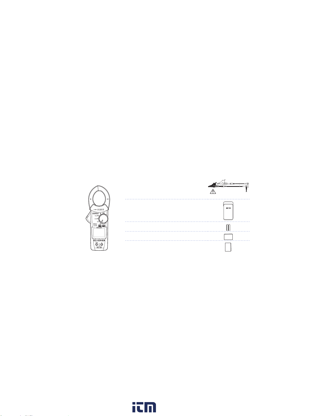
Package contents
When you receive the instrument, inspect it carefully to ensure that no damage occurred during
shipping. In particular, check the accessories, panel switches, and connectors. If damage is
evident, or if it fails to operate according to the specications, contact your authorized Hioki
distributor or reseller.
Model CM3286 or CM3286-01
AC Clamp Power Meter
Accessories
Model L9257 Connection Cord
(Model L4930 Connection Cable Set (1.2 m)
+ Model L4935 Alligator Clip Set)
CAT IV 600 V/ CAT III 1000 V/ CAT II 1000 V
Model C0203 Carrying Case
LR03 Alkaline battery ×2
Instruction Manual
Precautions Concerning Use of Equipment
That Emits Radio Waves
(only for the CM3286-01)
(p. 8)
Precautions during shipment
Handle it carefully so that it is not damaged due to a vibration or shock.
2
www. .com
information@itm.com1.800.561.8187
Page 7
Introduction
Trademarks
• Bluetooth® is a registered trademark of Bluetooth SIG, Inc.(USA). The trademark is used by
HIOKI E.E. CORPORATION under license.
• Android and Google Play are trademarks of Google, Inc.
• IOS is a registered trademark of Cisco in the U.S. and other countries.
• iPhone, iPad, iPad mini, iPad Pro, and iPod Touch are trademarks of Apple Inc.
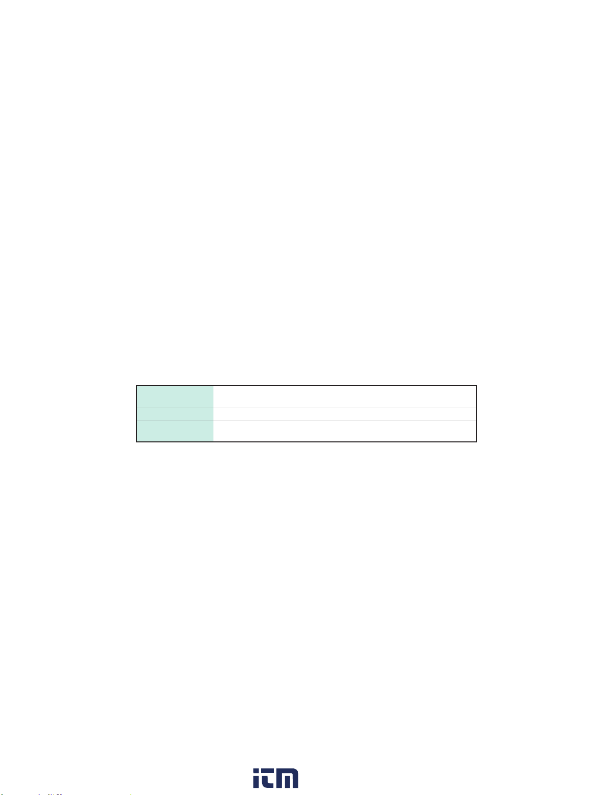
Accuracy
We dene measurement tolerances in terms of f.s. (fullscale), rdg. (reading), and dgt. (digit) values, with the
following meanings:
f.s. (maximum display
value or range)
rdg. (displayed value) The value currently being measured and indicated on the measuring instrument.
dgt. (resolution)
The maximum displayable value. This is usually the name of the currently selected
range.
The smallest displayable unit on a digital measuring instrument, i.e., the input value
that causes the digital display to show a "1" as the least-signicant digit.
3
www. .com
information@itm.com1.800.561.8187
Page 8

Options (sold separately)
9243 graber
L4937 マグネットアダプ
タ
L4934 小ワニグチ
マグネ付ストラップ
DM4910 熱電対
DT4911TestLead
DT4912TestLead
L4930 接続ケーブル
9243 graber
L4937 マグネットアダプ
タ
L4934 小ワニグチ
マグネ付ストラップ
L9207-10
DM4910 熱電対
DT4911TestLead
DT4912TestLead
L4930 接続ケーブル
L4931renketu
9243 graber
L4937 マグネットアダプ
タ
L4934 小ワニグチ
マグネ付ストラップ
L9207-10
DM4910 熱電対
DT4911TestLead
DT4912TestLead
L4930 接続ケーブル
L4931renketu
L4931 延長ケーブル
L4932(+9207-10cap)
L4933 コンタクトピン
L4935 ワニ口
9243 graber
L4937 マグネットアダプ
9243 graber
L4937 マグネットアダプ
タ
L4934 小ワニグチ
マグネ付ストラップ
L9207-10
DM4910 熱電対
DT4911TestLead
DT4912TestLead
L4930 接続ケーブル
L4931renketu
L4931 延長ケーブル
L4932(+9207-10cap)
L4933 コンタクトピン
L4935 ワニ口
L4936 バスバー
L4937 マグネットアダプ
タ
9243 graber
L4937 マグネットアダプ
タ
L4934 小ワニグチ
マグネ付ストラップ
L9207-10
DM4910 熱電対
DT4911TestLead
DT4912TestLead
L4930 接続ケーブル
L4931renketu
L4931 延長ケーブル
L4932(+9207-10cap)
9243 graber
L4937 マグネットアダプ
タ
L4934 小ワニグチ
マグネ付ストラップ
L9207-10
DM4910 熱電対
DT4911TestLead
DT4912TestLead
L4930 接続ケーブル
L4931renketu
L4931 延長ケーブル
L4932(+9207-10cap)
L4933 コンタクトピン
L4937 マグネットアダプ
タ
L4934 小ワニグチ
L4937 マグネットアダプ
タ
L4934 小ワニグチ
マグネ付ストラップ
Options (sold separately)
L4933 Contact Pin Set
L9207-10 Test Lead
1
*
L4934 Small Alligator Clip Set
L4935 Alligator Clip Set
L4930 Connection Cable Set
(1.2 m)
2
*
9243 Grabber Clip
L4936 Bus Bar Clip Set
L4937 Magnetic Adapter Set
L4931 Extension Cable Set
2
*
(1.5 m, with the coupling connector)
9804 Magnetic Adapter
L4932 Test Pin Set
L4938 Test Pin Set
( : See p. 8)
*1: CAT IV 600 V/ CAT III 1000 V/ CAT II 1000 V *6: 30 V AC/ 60 V DC
*2: CAT IV 600 V/ CAT III 1000 V *7: CAT III 600 V/ CAT II 600 V
*3: CAT III 1000 V *8: Can also be connected to the tip of
*4: CAT III 600 V
*5: CAT III 300 V/ CAT II 600 V
the L4932.
4
www. .com
8
*6,*
2
*
3
*
4
*
*
3
*
1
*
7
*
L4939 Breaker Pin Set
9290-10
Clamp On Adapter
information@itm.com1.800.561.8187
*5,*
3
8
4
*
4
*
Page 9
Safety Notes
Safety Notes
This instrument is designed to conform to IEC 61010 Safety Standards, and has been
thoroughly tested for safety prior to shipment. However, using the instrument in a way not
described in this manual may negate the provided safety features.
Before using the instrument, be certain to carefully read the following safety notes.
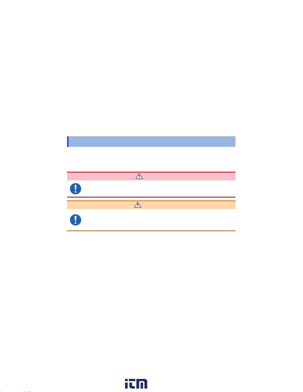
DANGER
Mishandling during use could result in injury or death, as well as damage
to the instrument. Be certain that you understand the instructions and
precautions in the manual before use.
WARNING
With regard to the electricity supply, there are risks of an electric shock, a heat
generation, a re, and an arc ash due to short‑circuit. Individuals using an
electrical measuring instrument for the rst time should be supervised by a
technician who has experience in electrical measurement.
5
www. .com
information@itm.com1.800.561.8187
Page 10
Safety Notes
WARNING
Protective gear
This instrument is measured on a live line. To prevent an electric shock, use
appropriate protective insulation and adhere to applicable laws and regulations.
Notation
In this document, the risk seriousness and the hazard levels are classied as follows.
Indicates information related
to the operation of the
instrument or maintenance
tasks with which the
operators must be fully
familiar.
Indicates prohibited actions.
Indicates the action which
must be performed.
DANGER
WARNING
CAUTION
Indicates an imminently
hazardous situation that will result
in death or serious injury to the
operator.
Indicates a potentially hazardous
situation that may result in death
or serious injury to the operator.
Indicates a potentially hazardous
situation that may result in minor
or moderate injury to the operator
or damage to the instrument or
malfunction.
IMPORTANT
6
www. .com
information@itm.com1.800.561.8187
Page 11

Symbols afxed to the instrument
Indicates cautions and hazards.
When the symbol is printed on the
instrument, refer to a corresponding
topic in the Instruction Manual.
Indicates that dangerous voltage may
be present at this terminal.
Indicates that the instrument may be
connected to or disconnected from a
live conductor.
Indicates a instrument that has been
protected throughout by double
insulation or reinforced insulation.
Indicates that the product incorporates
®
wireless technology.
FCC ID
Bluetooth
Indicates the ID number of the
wireless module certied by the U.S.
Federal Communications Commission
(FCC).
Indicates AC (Alternating Current).
Indicates DC (Direct Current).
Indicates a grounding terminal.
Indicates the Waste Electrical and
Electronic Equipment Directive (WEEE
Directive) in EU member states.
Indicates that the product conforms to
regulations set out by the EU Directive.
Indicates the identication number of a
IC
wireless module approved by Industry
Canada (IC).
Safety Notes
7
www. .com
information@itm.com1.800.561.8187
Page 12
Safety Notes
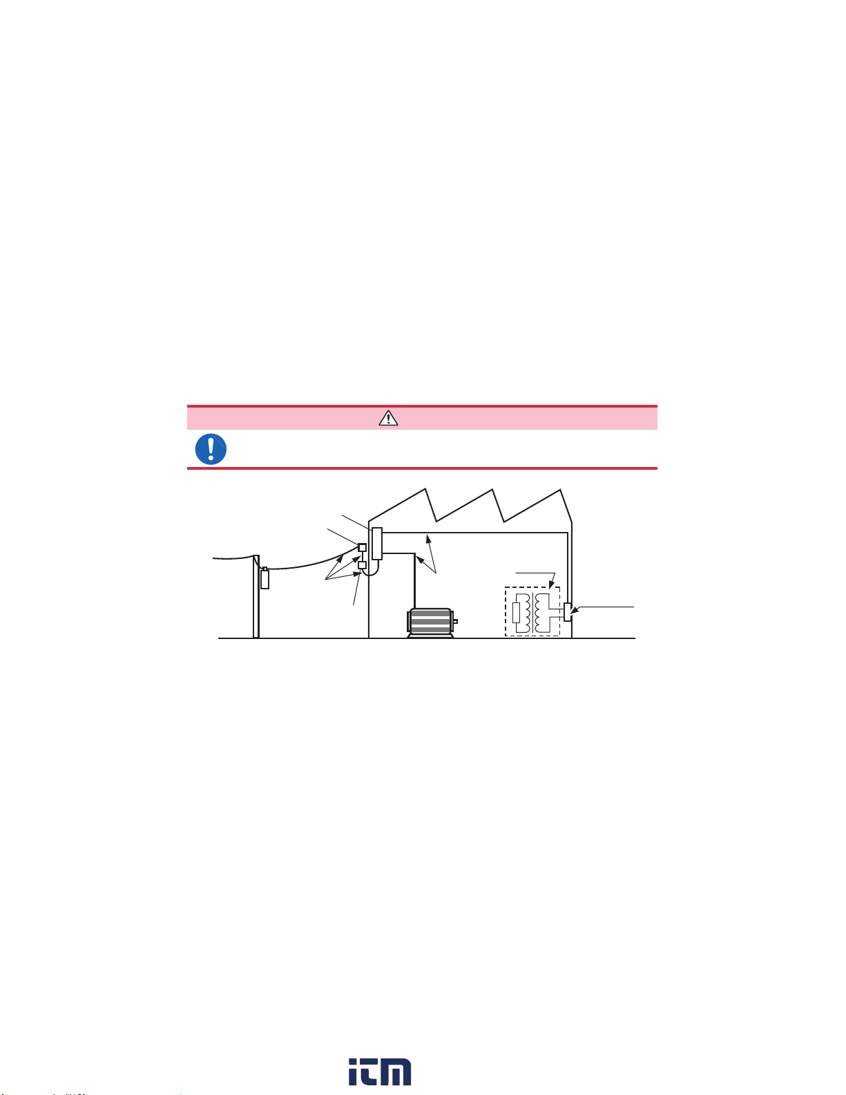
Measurement categories
To prevent an electric shock, do not exceed the lower of the ratings shown on
the instrument and connecting cords.
Distribution panel
Service entrance
Service drop
CAT IV
(≤600 V)
Power meter
8
DANGER
Internal wiring
CAT III
(≤1000 V)
Fixed installation
CAT II
(≤1000 V)
T
Outlet
www. .com
information@itm.com1.800.561.8187
Page 13
Usage Notes
Usage Notes
Follow these precautions to ensure safe operation and to obtain the full benets of the various
functions.
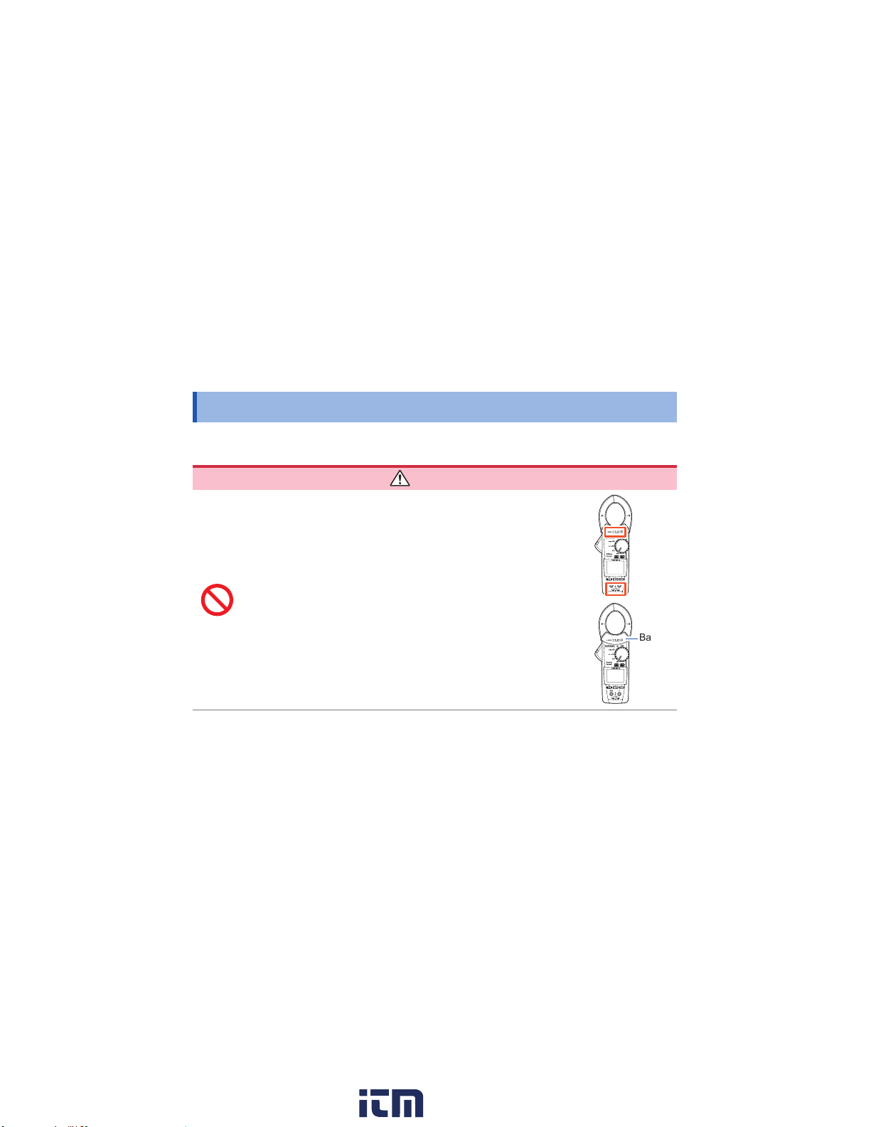
DANGER
• Do not use the instrument with circuits that exceed its
ratings or specications. Doing so may damage the
instrument or cause it to become hot, resulting in bodily
injury.
• The instrument must not be used to measure current in
high‑voltage lines (1000 V or more). Attempting to do so
could cause a short‑circuit or accident resulting in injury
or death. Also, do not perform measurement around a bare
conductor.
• To prevent an electric shock, do not touch any areas
beyond the barrier while the instrument is in use.
Barrier
9
www. .com
information@itm.com1.800.561.8187
Page 14
Usage Notes
10
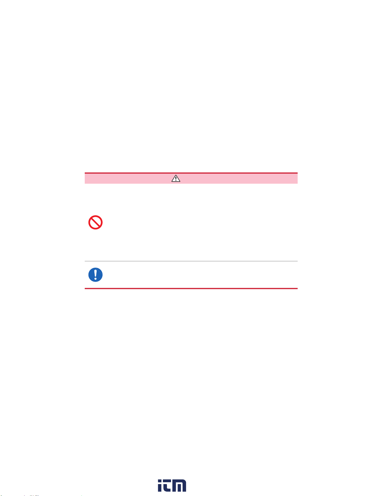
DANGER
• Do not short‑circuit two wires to be measured by bringing the clip or jaw
tip of the connecting cords into contact with them. Arcs or such grave
accidents are likely to occur.
• To prevent an electric shock, be careful to avoid shorting live lines with the
connecting cords tip.
• To prevent a short‑circuit or an electric shock, do not touch the metal part of
the connecting cords tip.
• The maximum measurement current varies with the frequency, and the
current that can be measured continuously is limited. Operating the
instrument at less than this limitation is referred to as derating. Do not
measure currents in excess of the derating curve. Doing so may result in
instrument damage or malfunction, a re, or a burn due to sensor heating.
• It is recommended to make measurements on the secondary side of the
distribution panel. Making measurements on the primary side of the panel,
where currents are higher, poses a higher risk of instrument or equipment
damage in the event of a short‑circuit.
www. .com
information@itm.com1.800.561.8187
Page 15
Usage Notes
WARNING
• Installing the instrument in inappropriate locations may cause a malfunction
of instrument or may give rise to an accident. Avoid the following locations.
• Exposed to direct sunlight or high temperature
• Exposed to corrosive or combustible gases
• Exposed to a strong electromagnetic eld or electrostatic charge
• Near induction heating systems (such as high‑frequency induction heating
systems and IH cooking equipment)
• Susceptible to vibration
• Exposed to water, oil, chemicals, or solvents
• Exposed to high humidity or condensation
• Exposed to high quantities of dust particles
• Although this instrument is designed to resist the ingress of dust and
dripping water, it is not entirely waterproof or dustproof. Therefore, to prevent
an electric shock, do not use it in a wet or dusty environment.
•
Battery may explode if mistreated. Do not short‑circuit, recharge, disassemble
or dispose of in re.
11
www. .com
information@itm.com1.800.561.8187
Page 16
Usage Notes
• Use only the specied connection cords. Use of any connection cord not
• To prevent an electric shock, set the rotary switch to the OFF position,
• To prevent instrument damage or an electric shock, use only the screw for
• Options may include connection cords which uses sleeves. To prevent
• If the sleeves are inadvertently removed during measurement, stop the
12
WARNING
specied by our company does not allow safe measurements.
disconnect all connection cords, and remove the instrument from the
measurement object before replacing the batteries.
securing the battery cover in place that is originally installed. If you have lost
a screw or nd that a screw is damaged, please contact your authorized Hioki
distributor or reseller for replacement.
a short‑circuit accident, be sure to use the connection cords with the
sleeves attached when performing measurements in the CAT III or CAT IV
measurement categories. (See "Measurement categories" (p. 8))
measurement.
www. .com
information@itm.com1.800.561.8187
Page 17
Usage Notes
CAUTION
• To avoid damage to the instrument, protect it from physical shock when
transporting and handling it. Be especially careful to avoid physical shock due to
dropping it.
• Do not place foreign objects between jaws or insert foreign objects into the gaps of
the sensor head. Doing so may worsen the performances of the sensor or interfere
with clamping action.
• Poor performance or damage from battery leakage could result. Observe the
cautions listed below.
• Do no mix old and new batteries, or different types of batteries.
• Be careful to observe the battery polarity during installation.
• Do not use batteries after their recommended expiry date.
• Do not leave depleted batteries inside the instrument.
• Replace batteries only with the specied type.
• Keep the jaw closed when not in use, to avoid accumulating dust or dirt on the
facing core surfaces, which could interfere with clamp performance.
• The cord is hardened in freezing temperature. Do not bend or pull it to avoid
tearing its shield or cutting cord.
IMPORTANT
Inverter secondary-side waveforms and waveforms that include a large noise component may not be
measured accurately.
13
www. .com
information@itm.com1.800.561.8187
Page 18
Usage Notes
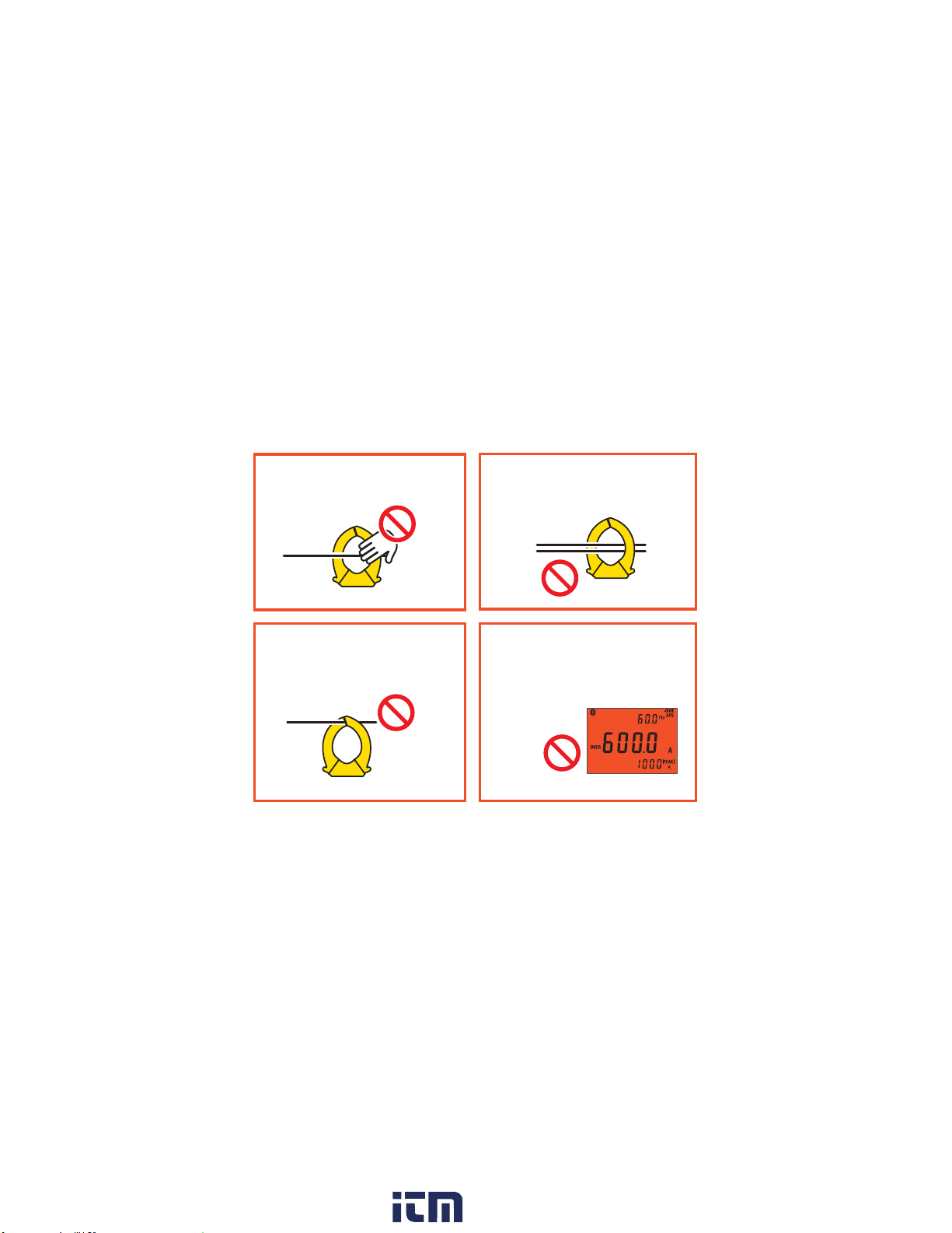
Current measurement precautions
14
Do not touch.
NO
Do not pinch wire
between jaws.
NO
Do not clamp
around two wires.
NO
Do not input
excessively high
currents or voltages.
NO
(Flashes red)
www. .com
information@itm.com1.800.561.8187
Page 19
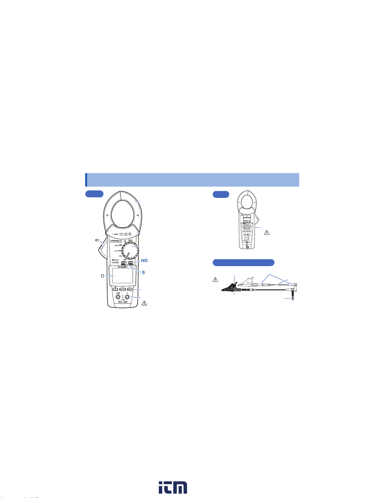
Part Names
Front
Lever
(CM3286-01)
Jaw
Barrier*
Rotary switch
Part Names
Rear
Battery cover
(p. 12)
HOLD key
LCD
* Do not touch any areas beyond the barrier while the instrument is in use.
SHIFT key
(Selects function indicated in
blue lettering.)
Operation keys
Voltage input terminal
(p. 9)
L9257 Connection Cord
Alligator clip
(p. 8)
Barrier*
Connector
Cord
Sleeve
15
www. .com
information@itm.com1.800.561.8187
Page 20
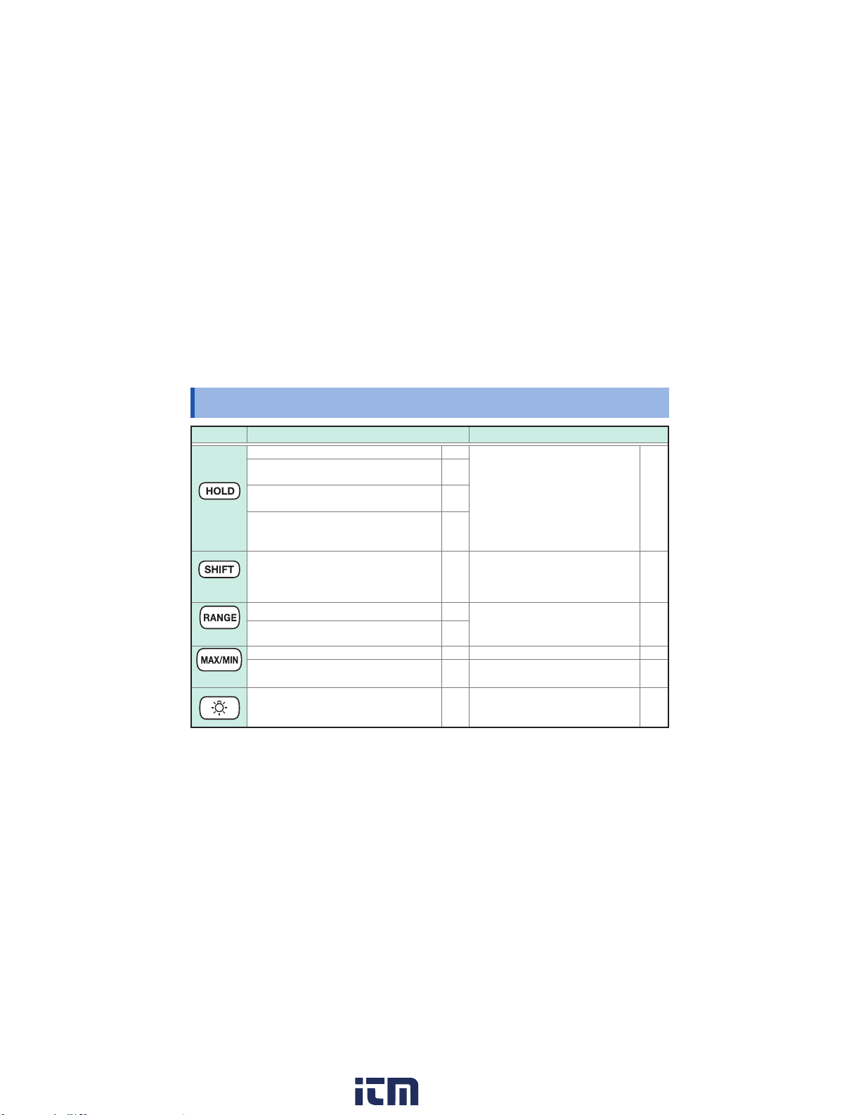
Operation keys
Operation keys
Key Short press Long press (1 sec.)
Activates/cancels manual hold operation p. 48
HOLD
SHIFT
RANGE
MAX/MIN
16
Start/stop integration, clears the integrated
energy value (during energy measurement)
Switches the setting (when setting meter
constants)
Switches from the connection display to
the measurement display (during 3-phase
power measurement)
Switches the information shown on the
measurement display
Switches ranges p. 51
Count up (when setting meter constants) p. 46
Displays and switches MAX/MIN/AVG value
Count down (when setting meter constants)
Toggles the display backlight on and off p. 55
p. 41
Activates/cancels automatic hold
p. 46
operation
p. 22
Switches between 3-phase/3-wire
and 3-phase/4-wire measurement
p. 24
during 3-phase power measurement
(setting is not stored)
High speed count up (when setting
meter constants)
p. 52
Cancels the display of MAX/MIN/AVG value
High speed count down (when setting
p. 46
meter constants)
Enables/disables external
communications (Bluetooth®) (only
for CM3286-01, setting is stored)
p. 48
p. 34
p. 35
–
p. 52
–
p. 59
www. .com
information@itm.com1.800.561.8187
Page 21
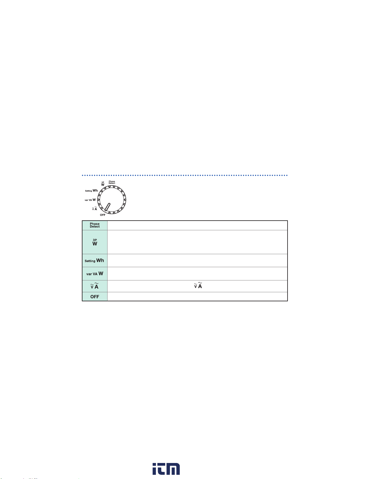
Rotary switch
"Phase Detection [Phase Detect]" (p. 38)
• "AC 3-phase measurement (3P3W, balanced) [3PW]" (p. 31)
• "AC 3-phase measurement (3P3W, unbalanced) [3PW]" (p. 32)
• "AC 3-phase measurement (3P4W, balanced) [3PW]" (p. 34)
• "AC 3-phase measurement (3P4W, unbalanced) [3PW]" (p. 35)
• "Single-phase Active Energy Measurement (Integrated Measurement) [Setting Wh]" (p. 40)
• "Single-phase Energy Meter Comparison Function [Setting Wh]" (p. 42)
• "AC single-phase measurement (1P2W) [var VA W]" (p. 29)
• "AC single-phase measurement (1P3W) [var VA W]" (p. 30)
"Current/Voltage Measurement (Frequency) [ ]" (p. 28)
Turns off the instrument.
Operation keys
When functions other than OFF is selected, the instrument turns on.
Select the desired function.
17
www. .com
information@itm.com1.800.561.8187
Page 22
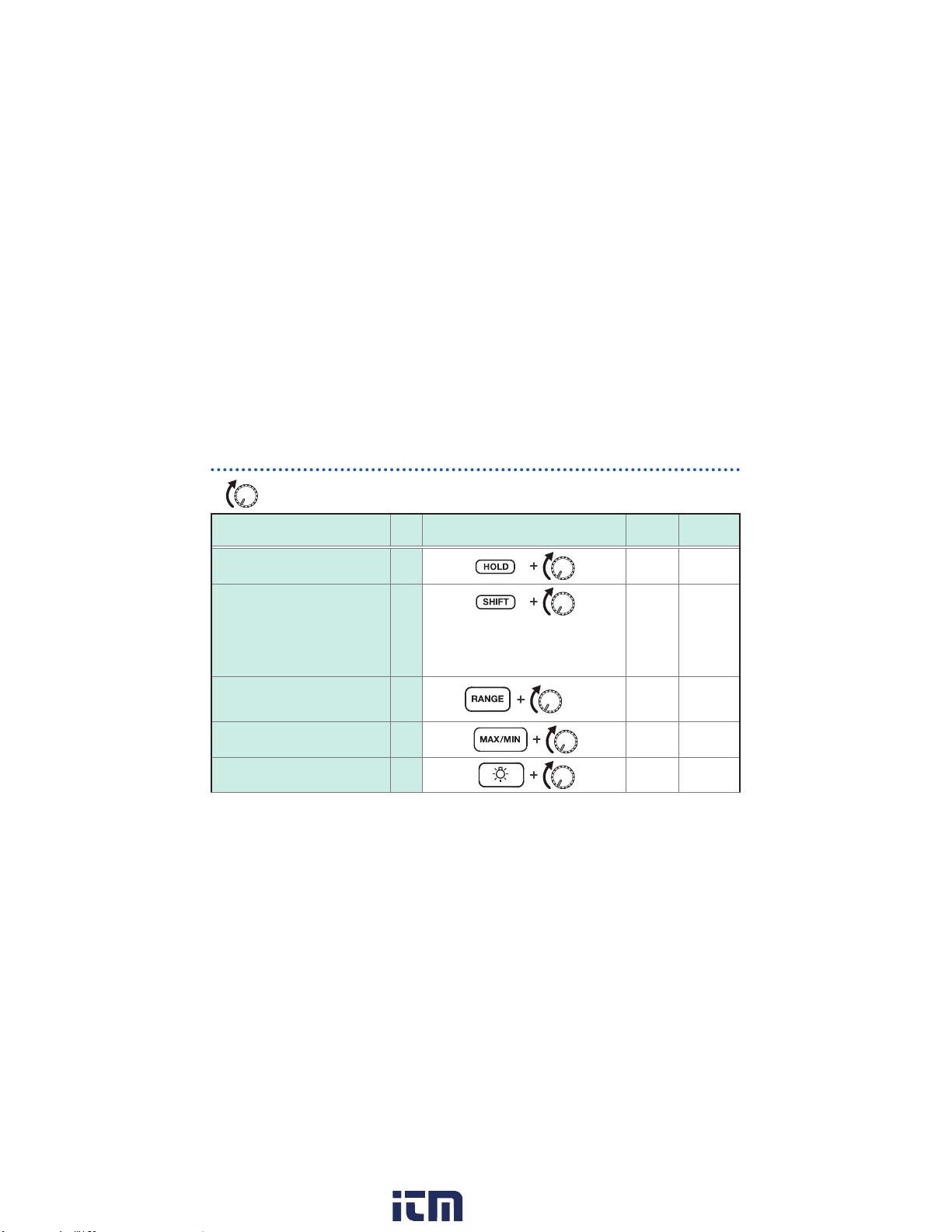
Operation keys
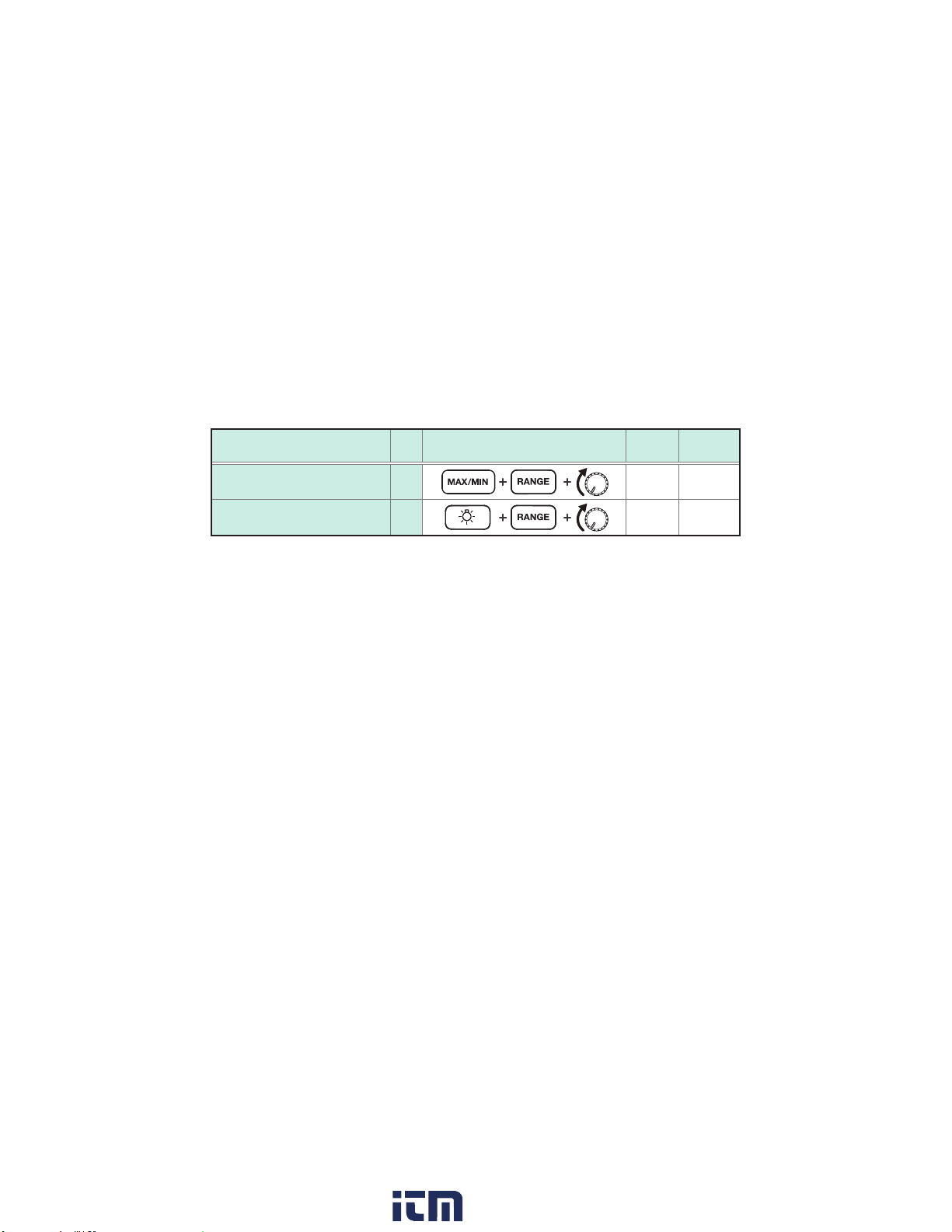
Power‑on Option Table (buzzer sound, resetting the instrument to the
factory settings, etc.)
+
Switching the auto power save
(APS) function (p. 55)
Displaying product information
or displaying all indicators
(Display varies depending on the
position of the rotary switch.)
Switching between balanced and
unbalanced operation (during AC
3‑phase power measurement)
Buzzer sound (ON/OFF) –
Switching the auto backlight off
function (p. 55)
Turn on the power while pressing the operation key.
(Turn the rotary switch from OFF.)
Setting See Operating instruction
18
Factory
setting
–
3PW: Serial number
–
Wh: Model number
W: Version of software
Besides the above: Displays all indicators
p. 32
p. 35
– ON Yes
3PW
retained?
ON –
– –
– –
ON Yes
Setting
www. .com
information@itm.com1.800.561.8187
Page 23
Setting See Operating instruction
Operation keys
Factory
setting
Setting
retained?
Selecting the CT ratio p. 56
Reset to the factory setting –
1/1 Ye s
– –
19
www. .com
information@itm.com1.800.561.8187
Page 24
Insert / Replace Batteries
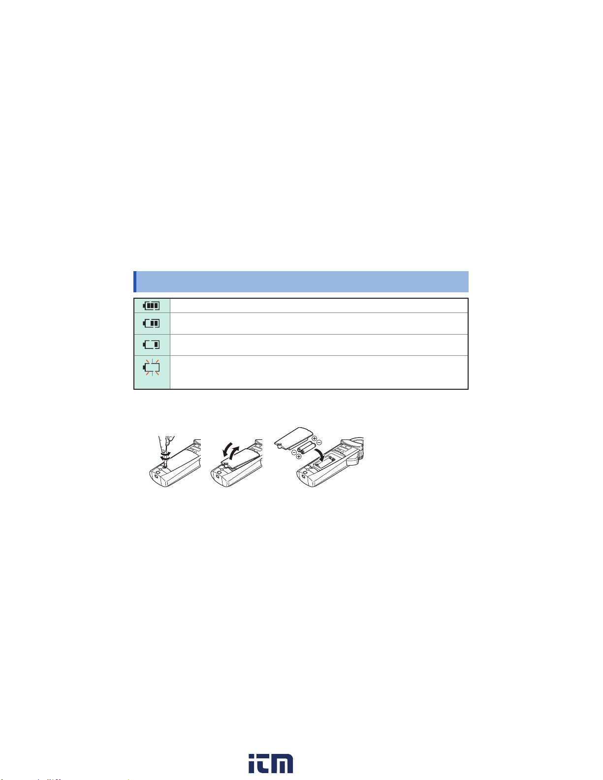
Insert / Replace Batteries
Fully charged.
As the battery charge diminishes, black charge bars disappear, one by one, from the left of the
battery indicator.
The battery voltage is low. Replace the batteries as soon as possible.
The instrument may lose power when the backlight turns on, when a buzzer sounds, etc.
The battery is exhausted. Replace with new batteries.
(Flashes)
Required items: No. 2 Phillips screwdriver and LR03 Alkaline battery ×2
Recommended screw tightening torque: 0.7 N・m
Exercise care to orient batteries properly.
3
20
4
1
2
5
www. .com
information@itm.com1.800.561.8187
Page 25
Inspection Before Measurement
Inspection Before Measurement
Verify that the instrument operates normally to ensure that no damage occured during storage
or shipping. If you nd any damage, contact your authorized Hioki distributor or reseller.
Check item
The battery cover is closed and its screw
has been securely tightened.
There is no foreign matter on the voltage
input terminals. (p. 15)
The battery voltage (p. 20) is sufcient.
There is no damage to the connection cords insulation,
and neither the white sheathing nor metal conductor
inside the wire are exposed.
The instrument is neither damaged nor cracked.
No indicators are missing.
→
(All indicators displayed)
21
www. .com
information@itm.com1.800.561.8187
Page 26
Screen / Basic Operation
Screen / Basic Operation
Setting the rotary switch to a position other than OFF causes the instrument to turn on and the
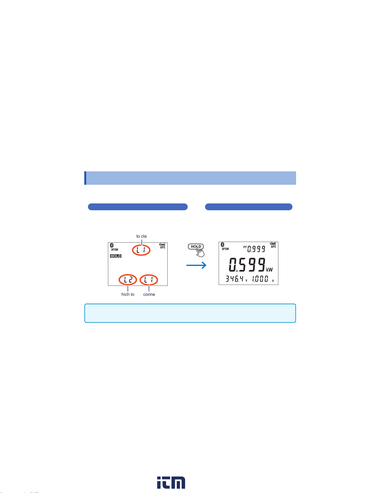
screen to activate. e.g.: During balanced 3-phase 3-wire active power measurement
Connection display Measurement display
Displays the connection locations for 3-phase
power measurement and phase detection.
Connects the wire.
Wire around which to clamp instrument
Black Red
Wires to which to clip connection cords
IMPORTANT
If measured with a wrong wire connection, a correct value does not appear.
22
Displays the measured value.
www. .com
information@itm.com1.800.561.8187
Page 27
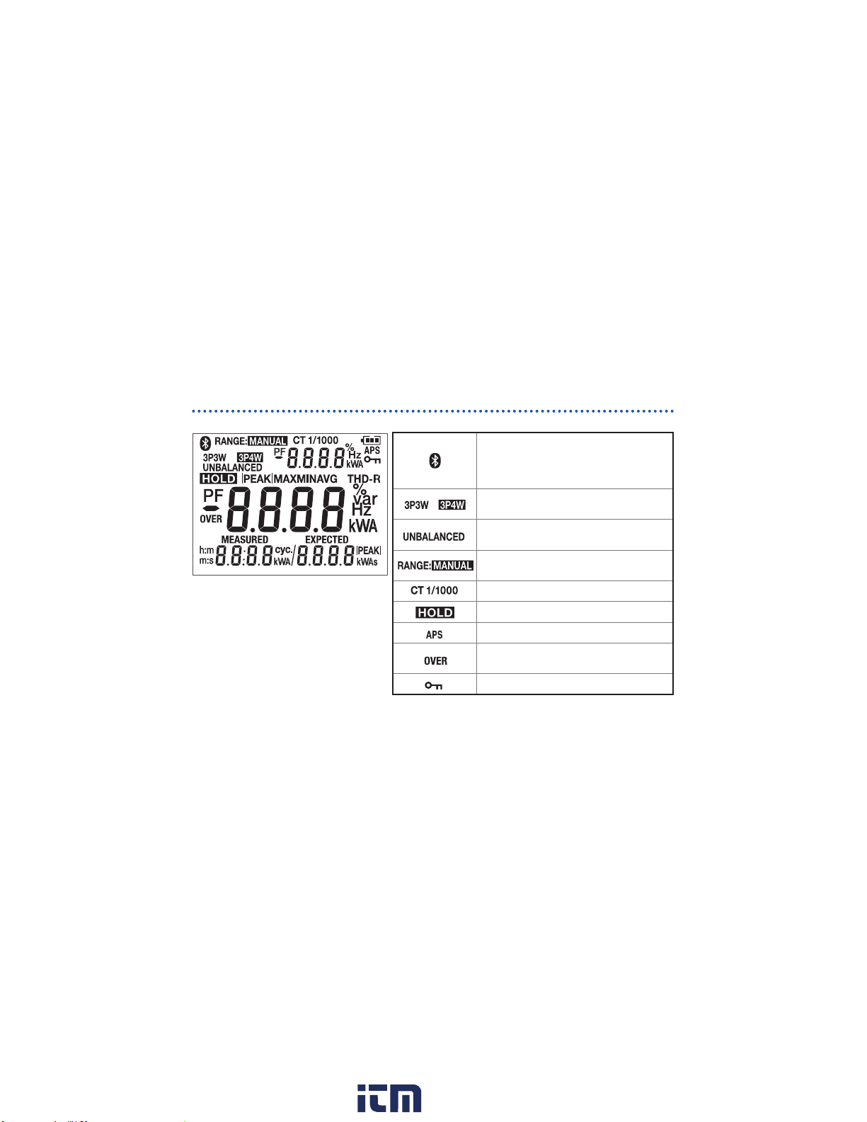
Screen display
(All indicators displayed)
"Error display" (p. 67)
"Warning display" (p. 67)
* The key lock feature may be activated
according to the usage state of the
application software.
Screen / Basic Operation
Appearing: Bluetooth® communications
function enabled
Flashing: Bluetooth
(only for CM3286-01)
,
Connection type (not shown during singlephase measurement)
Unbalanced mode operation (not shown
during balanced mode operation)
Manual range operation (not shown during
auto-range operation)
CT ratio (not shown during 1/1)
Measured value held
Auto power-off enabled
Current RMS value or voltage RMS value
exceeded range
Key lock enabled*
®
communications active
23
www. .com
information@itm.com1.800.561.8187
Page 28

Screen / Basic Operation
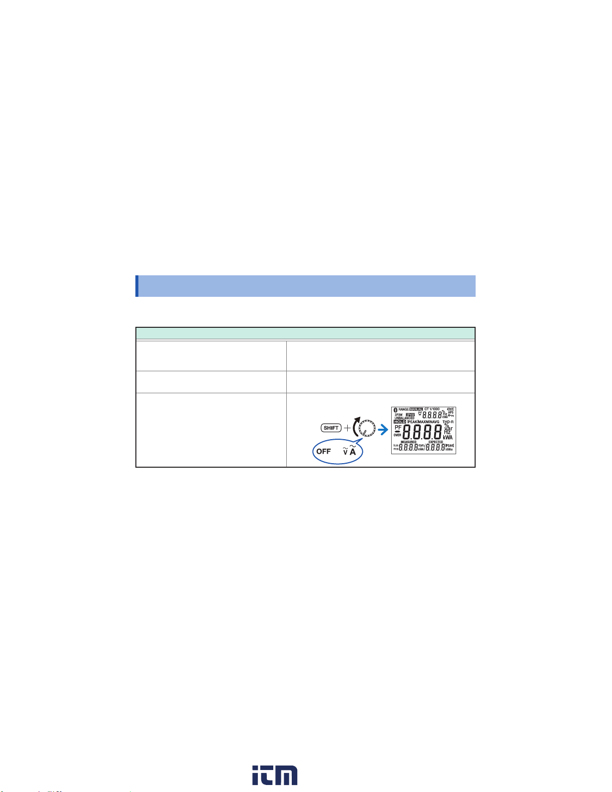
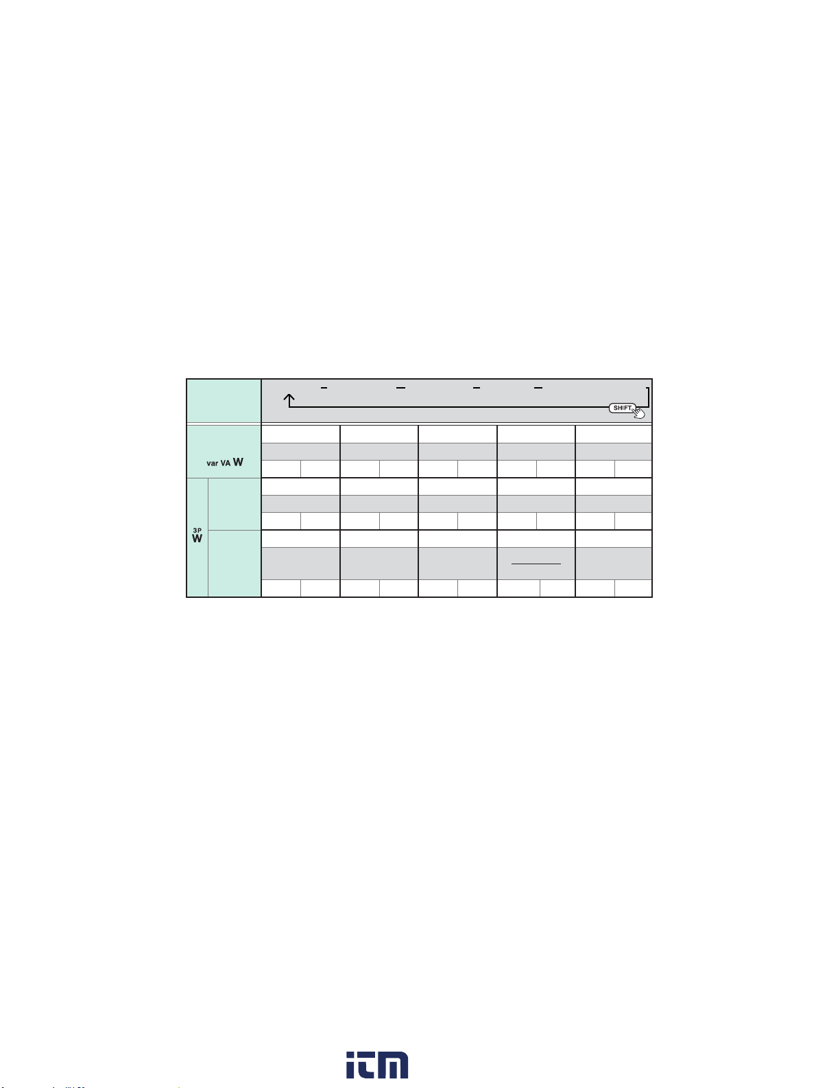
Switching the information shown on the measurement display
Able to switch using the SHIFT key (Excluding the and functions).
How to use this chart:
(Sub1 display)
FREQ
U
(Main display)
I
RMS
(Sub2 display)
–
(Sub3 display)
I
|PEAK|
Sub1
display
Main
display
Rotary switch
Current (frequency)
Voltage (frequency)
FREQ
: Current frequency
I
FREQ
: Voltage frequency
U
24
Current Voltage
FREQ
–
I
I
RMS
I
|PEAK|
I
RMS
U
RMS
FREQ
U
U
RMS
U
–
|PEAK|
: Current RMS value
: Voltage RMS value
Sub2 display
I
: Current peak value
|PEAK|
U
: Voltage peak value
|PEAK|
(All
indicators
displayed)
Sub3 display
www. .com
information@itm.com1.800.561.8187
Page 29
Active power
Rotary switch
(Main display)
Voltage/Power
factor
PF PF PF P P
P S Q PF
U
RMSIRMS
PF
Balance
mode*
1
P
U
RMSIRMS
P
Unbalance
mode*
P
: Single-phase active power
S
: Single-phase apparent power
Q
: Single-phase reactive power
PF
: Power factor
: Zero-cross phase angle 1
φ
1
P
P
3
+
1
P
1
Screen / Basic Operation
Apparent power Reactive power Power factor Zero-cross phase angle
U
U
3
P
S
2
P1
: Active power 1
S
: Apparent power 1
1
Q
: Reactive power 1
1
PF
: Power factor 1
1
: Zero-cross phase
φ
2
angle 2
RMSIRMS
2
PF
*
S
3P
RMSIRMS
S
3
S
S
+
+
1
2
1
2
*
3P
3
P
+
2
U
RMSIRMS
2
PF
*
Q
3P
U
RMSIRMS
Q
3
S
3
S
Q
Q
+
+
1
2
Q
2
1
P2
: Active power 2
S2
: Apparent power 2
Q2
: Reactive power 2
PF2
: Power factor 2
: Zero-cross phase
φ
3
angle 3
U
RMSIRMS
P
3P
*2
PF
3P
U
RMSIRMS
PF
3
P
P
P
+
+
1
2
Q
3
S
Q
PF1PF
2
3
S
S
+
+
1
2
3
2
P3
: Active power 3
S3
: Apparent power 3
Q3
: Reactive power 3
PF3
: Power factor 3
φ
U
RMSIRMS
P
3P
φ
3P
U
RMSIRMS
φ
–
φ
1
*2
3
φ
2
25
www. .com
information@itm.com1.800.561.8187
Page 30

Screen / Basic Operation
P3P:
Balanced 3-phase active power
S
:
Balanced 3-phase apparent power
3P
Q
:
Balanced 3-phase reactive power
3P
PF
:
Balanced 3-phase power factor
3P
: Zero-cross phase angle
φ
Notes(*) for table
*1 Value of the measured phase will be calculated and displayed.
*2 Different calculation methods are used for 3-phase/3-wire and 3-phase/4-wire circuits. For more
information, see the list of equations.
*3 Only 3-phase active power (
3-phase/3-wire circuits.
P
P
+
), active power 1 (
1
2
P
:
P
P
Unbalanced 3-phase active power
+
+
1
2
3
S
:
S
S
Unbalanced 3-phase apparent power
+
+
1
2
3
Q
:
Q
Q
Unbalanced 3-phase reactive power
+
+
1
2
3
P
P
P
+
+
1
2
3
S
φ
3P
P
), and active power 2 (
1
: Unbalanced 3-phase power factor
S
S
+
+
1
2
3
: 3-phase zero-cross phase angle
P
) are measured for
2
26
–
P
P
+
1
2
P
P
2
1
www. .com
information@itm.com1.800.561.8187
Page 31

Connecting the Clamp and Clips
Connecting the Clamp and Clips
Clamp
Current direction
Load
side
Power supply
Align the current direction mark with
the direction of the current.
side
Clip (Alligator)
Connect to metal part.
Clip (Magnetic adapter)
Connect to metal part.
(If unable to connect the magnetic adapter so that it sits
perpendicular to the terminal due to the weight of the voltage cord,
connect it at an angle so as to balance it against the weight of the
cord.)
27
www. .com
information@itm.com1.800.561.8187
Page 32

Current/Voltage Measurement (Frequency) [ ]
N
Current/Voltage Measurement (Frequency)
Current measurement
1
L/R/A
Clamp
*
"Switching the information
shown on the measurement
display" (p. 24)
If the screen turns red:
"Warning display" (p. 67)
The frequency display ashes
when frequency exceeds
999.9 Hz.
28
2
Power supply side
Voltage measurement
Red
L/R/A
Clip
2
Black
Power supply side
N
Load side
Load side
[ ]
Measurement
display*
Measurement
display*
www. .com
information@itm.com1.800.561.8187
Page 33

Power Measurement (Power/Power Factor)
Power Measurement (Power/Power Factor)
AC single‑phase measurement (1P2W)
Clamp
2
1
and clip
L/R/A
Power supply side
*
"Switching the information shown on
the measurement display" (p. 24)
If the screen turns red: "Warning
display" (p. 67)
N
[var VA W]
Red
Black
Load side
Measurement display*
29
www. .com
information@itm.com1.800.561.8187
Page 34

Power Measurement (Power/Power Factor)
AC single‑phase measurement (1P3W)
Clamp
and clip
1
2
L1
Black
N
Power supply side
L2
*
"Switching the information shown on
the measurement display" (p. 24)
If the screen turns red: "Warning
display" (p. 67)
30
[var VA W]
Red
Measurement display*
Black
Load side
Red
3
Clamp
and clip
www. .com
information@itm.com1.800.561.8187
Page 35

Power Measurement (Power/Power Factor)
AC 3‑phase measurement (3P3W, balanced)
Clamp and clip
1
2
L1/R/A
Connection display (p. 22)
Black
[3PW]
Red
L2/S/B
Power supply side
L3/T/C
3
*
"Switching the information shown on
the measurement display" (p. 24)
If the screen turns red: "Warning
display" (p. 67)
When the balanced 3-phase 3-wire zero-cross phase angle is less than −90° or exceeds 90°, the measured
value appears “ – – – – ”.
Measurement display
(calculation result)*
Load side
31
www. .com
information@itm.com1.800.561.8187
Page 36

Power Measurement (Power/Power Factor)
AC 3‑phase measurement (3P3W, unbalanced)
1
Connection display 1 (p. 22)
Clamp and clip
2
L1/R/A
Red
Black
L2/S/B
Power supply side
L3/T/C
• Proceed to the next step after
verifying that the measured
values shown on measurement
displays 1 and 2 are normal.
• If the screen turns red:
"Warning display" (p. 67)
3
Measurement display
(active power 1)
4
32
[3PW]
Clamp
5
and clip
Black
Red
Connection display 2
Load side
To next
page
www. .com
information@itm.com1.800.561.8187
Page 37

Measurement display
(active power 2)
6 7
3-phase active power
Active power 1
Active power 2
The measured value is cleared and returns to the initial connection display.
Power Measurement (Power/Power Factor)
Measurement display (calculation result)
(3-phase active power)
When the active power is
negative, “ − ” appears beside it.
Displays alternately
8
Long press
33
www. .com
information@itm.com1.800.561.8187
Page 38

Power Measurement (Power/Power Factor)
AC 3‑phase measurement (3P4W, balanced)
1
More than 1 sec.
Connection display (p. 22)
2
L1/R/A
L2/S/B
L3/T/C
Power supply side
N
Clamp
and clip
Red
Black
[3PW]
Measurement display
(calculation result)*
3
If the screen turns red:
"Warning display" (p. 67)
* "Switching the information shown on the measurement display" (p. 24)
34
Load side
www. .com
information@itm.com1.800.561.8187
Page 39

Power Measurement (Power/Power Factor)
AC 3‑phase measurement (3P4W, unbalanced)
Clamp and clip
1
More than 1 sec.
Connection display 1 (p. 22)
2
Red
L1/R/A
L2/S/B
L3/T/C
Power supply side
N
Black
5
Red
Black
3
Measurement display 1
Proceed to the next step after
verifying that the measured values
shown on measurement display 1
is normal.
(active power 1)
4
[3PW]
Clamp
and clip
Connection display 2
Load side
6
To next page
35
www. .com
information@itm.com1.800.561.8187
Page 40

Power Measurement (Power/Power Factor)
Measurement display 2
(active power 2)
L1/R/A
L2/S/B
L3/T/C
Power supply side
N
7
8
Red
Black
Clamp
and clip
Load side
Connection display 3
To
8
Proceed to the next step after
verifying that the measured
values shown on measurement
displays 2 and 3 are normal.
36
9
Measurement display 3
(active power 3)
To next page
www. .com
information@itm.com1.800.561.8187
Page 41

Measurement display 4 (calculation result)
(3-phase active power)
Power Measurement (Power/Power Factor)
10
Displays
alternately
When the active power
is negative, “ − ” appears
beside it.
The measured value is cleared and returns to the initial connection display.
• You can switch the information shown on the nal measurement display with the SHIFT key.
See "Switching the information shown on the measurement display" (p. 24)
• If the screen turns red: "Warning display" (p. 67)
11
Long press
Active power 3
3-phase active power
Active power 2
Active power 1
37
www. .com
information@itm.com1.800.561.8187
Page 42

Phase Detection [Phase Detect]
Phase Detection
1
Connection display (p. 22)
• The instrument will display
“– – – –” if open phase is detected
or if it is unable to make a
measurement.
• When the input is unstable, the
second connection display will not
show up.
* If not clipped within 10 seconds, it
is unable to make a measurement.
38
[Phase Detect]
Clip
2
L1/R/A
L2/S/B
Black
Power supply side
L3/T/C
Measurement display
Line voltage (1st measurement)
Red
Clip*
3
Black
Red
Connection display
Countdown display
Load side
To next page
www. .com
information@itm.com1.800.561.8187
Page 43

Measurement display
Display of results
Normal phase
Phase Detection [Phase Detect]
Reverse phase
Display appears
in the order of the
arrow.
Line voltage (2nd measurement)
Goes back to the rst display when the HOLD key is pressed.
(Lights red)
39
www. .com
information@itm.com1.800.561.8187
Page 44

Single-phase Active Energy Measurement (Integrated Measurement) [Setting Wh]
Single‑phase Active Energy Measurement
(Integrated Measurement)
1
Set the constant number to OFF.
2
or
40
3
L/R/A
Power supply side
N
[Setting Wh]
Clamp and clip
Red
Black
Load side
To next page
www. .com
information@itm.com1.800.561.8187
Page 45

Single-phase Active Energy Measurement (Integrated Measurement) [Setting Wh]
Set the instrument to power integration mode.
4
Start integration.
5
Stop integration.
6
• When the HOLD key is pressed during integration stop, the integrated energy clears and returns to the
display shown in Step 4.
• The measured values are automatically stored just before the instrument turns off due to low battery voltage.
Next time the instrument is turned on, the saved values will be displayed. (The measured values can be
cleared by pressing the HOLD key.)
• Range is xed when integration
starts. Change the range
before starting to integrate a
large power quantity or for an
extended period of time.
• Only the positive (consumption)
active power is added. Negative
(generation) active power is not
added.
Single-phase active power
Single-phase active energy
Elapsed time
41
www. .com
information@itm.com1.800.561.8187
Page 46

Single-phase Energy Meter Comparison Function [Setting Wh]
Single‑phase Energy Meter Comparison Function
[Setting Wh]
This function allows you to compare the actual energy value (measured value) from an energy meter with the
theoretical value.
There are two ways to start and stop integration:
• Start/stop at 1 cycle based on the energy meter’s instrument constant: 1-cycle mode
• Start/stop based on a xed amount of energy as measured by the energy meter: Fixed energy mode
IMPORTANT
Energy may not be calculated properly in the following circumstances:
• If the power line of the measurement object, instrument connection, or meter constant (for the watt-hour
meter) is set incorrectly.
• If integration is not started and stopped as described above.
• If the instrument is being used outside its operating temperature and humidity range.
• If the instrument is being used in close proximity to a device that emits powerful electromagnetic
radiation or a device that carries an electrical charge.
• If the instrument is being used in close proximity to a device that emits a strong magnetic eld, for
example a transformer, high-current circuit, or wireless device.
42
www. .com
information@itm.com1.800.561.8187
Page 47

1‑cycle mode
Mechanical meter
Once the disc has completed one revolution
Single-phase Energy Meter Comparison Function [Setting Wh]
Electronic meter
When the LED ashes once
Disc
Fixed energy mode
e.g.: With the xed energy set to 0.1 kWh
0.1 kWh digit
Start integration
Stop integration
LED
Start integration
Stop integration
Start integration
Stop integration
43
www. .com
information@itm.com1.800.561.8187
Page 48

Single-phase Energy Meter Comparison Function [Setting Wh]
Clamp and clip
1
Select the constant number or
2
xed energy*.
or
3
L/R/A
Power supply side
N
* Select xed energy mode if the energy meter’s disc rotates, or if
its LED ashes, quickly.
The constant can be changed.
"Watt-hour meter constants default setting value" (p. 47)
"Setting the desired meter constant" (p. 46)
Black
44
Red
Load side
To next page
www. .com
information@itm.com1.800.561.8187
Page 49

Single-phase Energy Meter Comparison Function [Setting Wh]
Set the instrument to power
4
integration mode.
Start integration.
5
• Only the positive (consumption) active power is added. Negative
(generation) active power is not added.
• Range is xed when integration starts. Change the range before starting
to integrate a large power quantity or for an extended period of time.
Stop integration.
6
When the HOLD key is pressed during integration stop, the integrated energy clears and returns to the display
shown in Step 4.
Single-phase active power (measured value)
Elapsed time
Energy (theoretical value)
Energy ratio (Measured value/theoretical value)
Energy difference (Measured value − theoretical
value)
Energy (Measured value)
45
www. .com
information@itm.com1.800.561.8187
Page 50

Single-phase Energy Meter Comparison Function [Setting Wh]
Setting the desired meter constant
Set after conducting the procedures 1 and 2 of "Single-phase Energy Meter Comparison Function [Setting
Wh]" (p. 42)
Select the portion you wish to change.
1
Change the value.
2
or
46
The selected portion will ash.
Set the value shown on the meter.
The set value will be stored.
• Press the SHIFT key to go back to the measurement
display.
• The changed nal value will be the setting value.
• "Watt-hour meter constants default setting value" (p. 47)
www. .com
information@itm.com1.800.561.8187
Page 51

Single-phase Energy Meter Comparison Function [Setting Wh]
Watt‑hour meter constants default setting value
No.01 to No.10: 1-cycle mode
0.10 kWh to 0.01 kWh: Fixed energy mode
Changing the
SET No. Setting value
oFF None (single-phase
energy measurement)
01 3200 cyc./1 kWh
02 1600 cyc./1 kWh
03 1200 cyc./1 kWh
04 1000 cyc./1 kWh
05 600 cyc./1 kWh
06 500 cyc./1 kWh
Updated settings are stored by the instrument.
setting value
Enable:
Disable: –
SET No. Setting value
07 300 cyc./1 kWh
08 250 cyc./1 kWh
09 150 cyc./1 kWh
10 125 cyc./1 kWh
0.10 kWh 0.10 kWh –
0.05 kWh 0.05 kWh –
0.01 kWh 0.01 kWh –
Changing the
setting value
Enable:
Disable: –
47
www. .com
information@itm.com1.800.561.8187
Page 52

Manual Hold / Auto Hold
Manual Hold / Auto Hold
MANUAL HOLD AUTO HOLD
To measurement object
>
Measured value is retained.
(
Pressing the HOLD key again cancels
the measured value hold function.
(
and disappears)
appears)
48
→ ashes.
Press for 1 sec.
To measurement
object
(Measured value
stabilizes.)
Measured value is
automatically retains.
(
Pressing the HOLD key for 1 second cancels the auto hold
function. (
See the next page for auto hold conditions.
appears)
and disappears)
Disconnect
www. .com
information@itm.com1.800.561.8187
Page 53

Manual Hold / Auto Hold
Auto hold conditions
Measured value is automatically retained when the following two conditions are satised:
• When the range over which the measured value is uctuating stabilizes within the uctuation range
described in the table in the next page.
• When the measured value exceeds the threshold value described in the table in the next page.
Ο: Held value
Auto hold
e.g.: 99.0 A
Fluctuation range
Threshold value
e.g.: 6.0 A
Measured
value
Auto hold
e.g.: 100.0 A
Fluctuation range
Fluctuation
range
Start
If the measured value* (voltage, current, or active power) falls below the threshold value once and the
two conditions are satised again after automatic retaining, the measured value at that point will retain
automatically.
* Either the current RMS value or voltage RMS value for power.
End
End
Start
Measurement
Start
End
Time
49
www. .com
information@itm.com1.800.561.8187
Page 54

Manual Hold / Auto Hold
Measurement
function*
AC current Current RMS value
AC voltage Voltage RMS value
Single-phase power,
balanced 3-phase
power
* No auto-hold function is available for single-phase active energy measurement.
Fluctuation range Threshold value
6.000 A range: within 60 counts
60.00 A range: within 60 counts
600.0 A range: within 60 counts
within 120 counts
Current and voltage RMS values satisfy
above conditions, and active power is
within 5 counts.
Current RMS value
6.000 A range: 59 counts
60.00 A range: 59 counts
600.0 A range: 59 counts
Voltage RMS value
799 counts
Current and voltage RMS values are
within the above counts.
50
www. .com
information@itm.com1.800.561.8187
Page 55

Switching Ranges
e.g.: During current measurement
AUTO range MANUAL 60.00 A range
MANUAL 600.0 A range
MANUAL 6.000 A range
Switching Ranges
51
www. .com
information@itm.com1.800.561.8187
Page 56

MAX/ MIN/ AVG
MAX/ MIN/ AVG
1
2
• Switches to manual range when it is auto range. (
• The MAX/MIN/AVG measurement will be continued during hold function.
• The maximum, minimum, and average function cannot be used during Wh function and phase detect
function operation.
• The maximum, minimum, and average values are automatically stored just before the instrument turns off
due to low battery voltage. Next time the instrument is turned on, the saved values will be displayed. (The
measured values can be cleared by pressing the HOLD key.)
To measurement object
Present value
: To switch the main display.
(long press) or (switching functions): MAX/MIN/AVG measurement function is cleared.
appears)
52
www. .com
information@itm.com1.800.561.8187
Page 57

e.g.:
During current measurement
MAX/ MIN/ AVG
Maximum measured value of the current RMS*
Maximum measured value's time*
*1 The maximum, minimum, and average values for the main display’s measured value is shown.
(However, only the maximum and average values are shown during peak value measurement.
Also, only the maximum and minimum values are shown during zero-cross phase angle measurement.)
*2 Measured value's update time is displayed when maximum or minimum value is shown. Elapsed time
from the start of maximum, minimum, and average function is displayed when present or average value is
shown.
2
1
53
www. .com
information@itm.com1.800.561.8187
Page 58

MAX/ MIN/ AVG
|PEAK|
MAX
Measured value
(RMS value)
MAX/MIN/AVG of
the RMS value
|PEAK|
AVG: Average value after pressing the MAX/MIN key
MAX: Maximum value after pressing the MAX/MIN key
MIN: Minimum value after pressing the MAX/MIN key
|PEAK|: Maximum value of the absolute value of the waveform during the display update interval
MIN
Display refresh interval
54
Waveform
www. .com
information@itm.com1.800.561.8187
Page 59

Backlight / Auto Power Save (APS)
30
sec
10
sec
10
sec
Backlight / Auto Power Save (APS)
Backlight Auto power save (APS)
Backlight OFF
min
Backlight ON
No operation for approx. 40 sec.: Backlight off
Switching the auto backlight off function: p. 18
15
No input and
operation for
approx. 15 min.
• Set the rotary switch to OFF when restarting the instrument after the APS function.
• The APS function is disabled while displaying the MAX/MIN/AVG value and
during energy integration.
®
• Bluetooth
communications are treated as an operation for the purpose of the
APS function.
Flashes
Power OFF
(Ordinarily on)
Switching the function: p. 18
sec
30
Power OFF 30 sec. before
Power OFF 10 sec. before
sec
10
55
www. .com
information@itm.com1.800.561.8187
Page 60

Measurement Using the Clamp Adapter
Measurement Using the Clamp Adapter
A clamp adapter (sold separately) can be used to measure currents that are larger than the rated
input current.
Select the CT ratio.
1
Clamp
3
Clamp adapter
(e.g.: Model 9290-10)
The instrument
56
Conductor
Clamp
2
Rotary switch CT ratio
A 1/1 (not shown)
W 1/10
Wh 1/100
3PW 1/1000
Set the CT ratio as appropriate for the clamp adapter.
(e.g.: For the 9290-10 Clamp on Adapter, 1/10)
Perform measurement.
4
www. .com
information@itm.com1.800.561.8187
Page 61

Bluetooth® Communications (only for CM3286-01)
Bluetooth® Communications
The CM3286-01 is a clamp-style meter with Bluetooth® low energy support. When the Bluetooth® function
is enabled, you can review measurement data and create measurement reports on mobile devices (iPhone,
iPad, iPad Mini, iPad Pro, iPod Touch, and Android™ devices). For more information about this functionality,
see the Help function in the application software GENNECT Cross.
Install the GENNECT Cross on your mobile device. (p. 58)
1
Enable the Bluetooth® function on the CM3286‑01. (p. 59)
2
Launch the GENNECT Cross and pair it with the CM3286‑01.
3
(p. 60)
Select the General Measurement, Logging (Recording),
4
Waveform Graph, Electricity Theft Detection, or Harmonic
Analysis function. (p. 61)
(only for CM3286‑01)
Press for 1
sec.
57
www. .com
information@itm.com1.800.561.8187
Page 62

Bluetooth® Communications (only for CM3286-01)
Installing the application software GENNECT Cross
Search for “GENNECT Cross” on the App Store from your iPhone, iPad or other Apple device, or on Google
Play from your Android device. Then download and install the GENNECT Cross. You will need an Apple ID to
download the app from the App Store, or a Google account to download the app from Google Play. For more
information about how to register an account, contact the store at which you purchased your device.
• Because the CM3286-01 emit radio waves, use in a country or region where they have not been
approved may be subject to nes or other penalties as a violation of applicable laws or regulations. For
more information, see the attached “Precautions Concerning Use of Equipment That Emits Radio Waves”
or go to our website.
• The CM3286-01 availability is limited to certain countries. For more information, contact your authorized
Hioki distributor or reseller.
®
• Bluetooth
etc.) as well as distance from the oor or ground. To ensure stable measurement, verify adequate signal
strength.
• Although this application software is provided free of charge, downloading or use of the application
software may incur Internet connection charges. Such charges are the sole responsibility of the user.
• This application software is not guaranteed to operate on all mobile devices.
communications range varies greatly with distance from obstructions (walls, metal obstruction,
58
www. .com
information@itm.com1.800.561.8187
Page 63

Bluetooth® Communications (only for CM3286-01)
Turning on the Bluetooth® function
Bluetooth® function OFF Bluetooth® function ON
Press for 1 sec.
icon will ash when the instrument is
connected to a mobile device.
59
www. .com
information@itm.com1.800.561.8187
Page 64

Bluetooth® Communications (only for CM3286-01)
Pairing the app with the CM3286‑01
2
1
• When the app is launched for the rst time (before being paired with any instrument), the Instrument
Settings screen will be displayed.
• While the mobile device is displaying the Instrument Settings screen, simply move it close to a CM3286-
01 to automatically pair it with the instrument (the app can be paired with up to 8 instruments).
• Allow about 5 to 30 seconds for the instrument to pair with the app after being turned on. If the instrument
fails to pair within 1 minute, relaunch GENNECT Cross and cycle the instrument’s power.
3
60
www. .com
information@itm.com1.800.561.8187
Page 65

Bluetooth® Communications (only for CM3286-01)
Making measurements with the Bluetooth® function
Select the General Measurement, Logging (Recording), Waveform Graph, Electricity Theft Detection,
or Harmonic Analysis function on the Home screen. For more information about each function, see the Help
function in the GENNECT Cross.
General Measurement
Saves measured values from
multiple channels.
Logging (Recording)
Simple logging
(up to 24 hours)
Waveform Graph
Simple oscilloscope
(voltage/current)
61
www. .com
information@itm.com1.800.561.8187
Page 66

Bluetooth® Communications (only for CM3286-01)
Electricity Theft Detection
Creates a result report by measuring current and
energy.
62
Harmonic Analysis
Analyzes levels, content percentages, and total
distortion (voltage, current).
www. .com
information@itm.com1.800.561.8187
Page 67

Repairs, Inspections, and Cleaning
Repairs, Inspections, and Cleaning
WARNING
Customers are not allowed to modify, disassemble, or repair the instrument.
Doing so may cause a re, an electric shock, or a injury..
Cleaning
• To clean the instrument, wipe it gently with a soft cloth moistened with water or mild detergent.
• Measurements are degraded by dirt on the mating surfaces of the jaw, so keep the surfaces
clean by gently wiping with a soft, dry cloth.
• Wipe the LCD gently with a soft, dry cloth.
Disposal
Handle and dispose of the instrument and batteries in accordance with local regulations.
Precautions during shipment
Be sure to observe the following precautions:
• To avoid damage to the instrument, remove the batteries, accessories, and options from
the instrument. Moreover, be sure to pack in a double carton. Damage that occurs during
transportation is not covered by the warranty.
• When sending the instrument for repair, be sure to include details of the problem.
63
www. .com
information@itm.com1.800.561.8187
Page 68

Repairs, Inspections, and Cleaning
Calibrations
The calibration period varies depending on the status of the instrument or installation
environment. We recommend that the calibration period be determined in accordance with the
status of the instrument or installation environment. Please contact your Hioki distributor to have
your instrument periodically calibrated.
64
www. .com
information@itm.com1.800.561.8187
Page 69

Troubleshooting
Troubleshooting
If damage is suspected, check the following before contacting your authorized Hioki distributor
or reseller.
Symptom Verication and/or Solution
• The instrument is indicating an
abnormal measured value for
current.
• When readings from the
instrument are compared with
those of another clamp-on current
meter, the measured values differ.
• Is the measured current value too small for the instrument’s
measurement range?
Wrap the wire around the jaw one or more times. Each additional
wrap of the wire will increase the measured value, so that wrapping
it once yields a measured value that is twice the actual value and
wrapping it twice yields a measured value that is three times the
actual value.
• Are the tips of the jaw open?
• Is the jaw damaged?
If the sensor is damaged or cracked, it will not be able to measure
current accurately. Send the instrument for repair.
• The instrument cannot accurately measure waveforms that contain
a component that falls outside the frequency characteristics range.
• Since the instrument performs true RMS measurement, it can
accurately measure distorted waveforms. When measuring a
distorted waveform, the measured value will differ from a clamp-on
current meter that uses the averaging method.
65
www. .com
information@itm.com1.800.561.8187
Page 70

Troubleshooting
Symptom Verication and/or Solution
• The current value is larger than
expected.
• A current value is displayed even
though there is no input.
• A sound is being emitted by the
instrument’s jaw.
• The measured value does not
appear.
• No measured value is displayed,
even when the connection cords
are shorted.
66
• The instrument cannot perform measurement accurately in the
presence of a strong magnetic eld from a source such as a nearby
transformer or high-current circuit or in the presence of a strong
electric eld from a source such as a wireless device.
• The jaw may emit sound when measuring AC currents in excess of
approx. 500 A, however, there is no effect on the measurement.
• Insert the connection cords all the way.
• Use the proper measurement method.
If no measured value is displayed after attempting the above two
solutions, the instrument may be broken. Have the instrument
repaired.
www. .com
information@itm.com1.800.561.8187
Page 71

Error display
Error
display
Err 001 ROM error Program
Err 002 ROM error Adjustment data
Err 005 ADC error Hardware malfunction
Err 008
Bluetooth
error
Description Solution
®
Hardware malfunction
(only for CM3286-01)
Warning display
Display Buzzer Cause Solution
Troubleshooting
Repair is necessary. Please contact your
authorized Hioki distributor or reseller.
Flashes
red
–
Measurement resulted in
a negative active power
value.
The instrument may not be
connected properly. Reconnect
the instrument to the circuit
being measured.
67
www. .com
information@itm.com1.800.561.8187
Page 72

Troubleshooting
Display Buzzer Cause Solution
e.g.: for current
measurement
Flashes
red
Intermittent
sound
A current or voltage
exceeding the maximum
input was input to the
instrument.
Stop measurement
immediately as the current or
voltage cannot be measured
by the instrument. For current
measurement, the optional
9290-10 can be used to
measure currents of up to
1000 A AC.
When manual range is 6 A
and 60 A range, this warning
display will not appear.
e.g.: for current
measurement
68
Lights
red
A current or voltage
–
exceeding the range
was input while using a
manual range.
Change the measurement
range or select the AUTO
range.
www. .com
information@itm.com1.800.561.8187
Page 73

Troubleshooting
Display Buzzer Cause Solution
Lights
red
Intermittent
sound
Phase detection
indicated reverse phase.
69
www. .com
information@itm.com1.800.561.8187
Page 74

Specications
General Specications
Operating environment Indoors, pollution degree 2, altitude up to 2000 m (6562 ft.)
Operating temperature
and humidity
Storage temperature and
humidity
Dustproof and
waterproof
Temperature −25°C (−13°F) to 65°C (149°F)
Humidity −25°C (−13°F) or higher but less than 40°C (104°F):
80% RH or less
40°C (104°F) or higher but less than 45°C (113°F):
60% RH or less
45°C (113°F) to 65°C (149°F): 50% RH or less
(no condensation)
Temperature −25°C (−13°F) to 65°C (149°F)
Humidity −25°C (−13°F) or higher but less than 40°C (104°F):
80% RH or less
40°C (104°F) or higher but less than 45°C (113°F):
60% RH or less
45°C (113°F) to 65°C (149°F): 50% RH or less
(no condensation)
Remove batteries before storing the instrument.
Grip except lever: IP54 (EN 60529)
Jaw, barrier, lever: IP50 (EN 60529)
Specications
71
www. .com
information@itm.com1.800.561.8187
Page 75

Specications
Standards (other
than wireless
communications
functionality)
Power supply LR03 alkaline battery ×2
Continuous operating
time
Interface (only for
CM3286-01)
Dimensions Approx. 82W × 241H × 37D mm (3.23″W × 9.49″H × 1.46″D)
Jaw dimensions Approx. 79W × 20D mm (3.11″W × 0.79″D)
Maximum measurable
conductor diameter
Mass Approx. 450 g (15.9 oz.) (including batteries)
Product warranty period 3 years
Accessories See p. 2
Options See p. 4
Safety: EN 61010
EMC: EN 61326
Rated supply voltage: 1.5 V DC ×2
Maximum rated power: 550 mVA
Approx. 25 hours (Backlight display off, Bluetooth
as a referential)
Approx. 18 hours (Backlight display off, Bluetooth
as a referential)
®
Bluetooth
46 mm (1.81″)
4.0LE ( )
®
communication off, at 23°C,
®
communication on, at 23°C,
72
www. .com
information@itm.com1.800.561.8187
Page 76

Input/Output/Measurement Specications
Basic Specications
Specications
Measurement items
Maximum input current See the frequency derating characteristics (p. 74).
Maximum measuring
voltage
Maximum rated voltage
to earth
Maximum rated voltage
to terminal
Measurement method True RMS measurement with digital sampling
Measurement terminal COM terminal and V terminal
Input impedance 1 M
AC current RMS value/AC current peak value (no polarity)/AC current frequency
AC voltage RMS value/AC voltage peak value (no polarity)/AC voltage frequency
Single-phase active power/Single-phase apparent power/Single-phase reactive
power/Single-phase power factor/Single-phase zero-cross phase angle
Balanced 3-phase active power/Balanced 3-phase reactive power/Balanced
3-phase apparent power/Balanced 3-phase power factor/Balanced 3-phase
zero-cross phase angle
Single-phase active energy (only positive values added)/Phase detection
(up to 200 Hz, 600 A or less; above 200 Hz, 120000 A・Hz or less)
600 V AC
600 V AC (Measurement category IV)
1000 V AC (Measurement category III)
Anticipated transient overvoltage 8000 V
or greater
Ω
73
www. .com
information@itm.com1.800.561.8187
Page 77

Specications
Display update interval 2 times/sec.
Response time 1 sec.
Crest factor 3 or less for current 6 A and 60 A range
Zero-display range • Voltage and current RMS values: 29 counts or less
Frequency derating
characteristics
1.6 or less for current 600 A range and voltage 600 V range
• If they fall within the zero-display range, current (voltage) peak values and
active/apparent/reactive power values are shown as zero, while current
(voltage) frequency, power factor, and zero-cross phase values are shown as
“– – – –.”
• A value of 0 is used in single-phase active energy calculations.
700
600
500
400
300
200
100
Maximum input current [A]
0
10 100 1000 10000
Frequency [Hz]
74
www. .com
information@itm.com1.800.561.8187
Page 78

Accuracy Specications
Specications
Conditions of
guaranteed accuracy
Input conditions for
guaranteed accuracy
Effects of external
magnetic elds
Effects of conductor
position
Temperature coefcient Add “measurement accuracy × 0.1/°C” (excluding 23°C±5°C (73°F±9°F)).
Effects of sensor phase ±1° (50 Hz to 60 Hz)
See “Accuracy Table” (p. 79)
Guaranteed accuracy period: 1 year
Guaranteed accuracy period after adjustment made by Hioki: 1 year
Guaranteed accuracy for temperature and humidity:
23°C±5°C (73°F±9°F), 80% RH or less (no condensation)
Number of jaw open/close cycles: 10000 times or less
Sine wave input
DC/AC 60 Hz, with a 400 A/m external magnetic eld:
0.10 A or less
At all positions around the jaw’s center-point reference: within ±0.5%
(100 A input, f ≤100 Hz)
75
www. .com
information@itm.com1.800.561.8187
Page 79

Specications
Harmonic Measurement Specications (only for CM3286-01)
All operations are performed by the GENNECT Cross application software. The following specications apply
only to use of the GENNECT Cross’s harmonic analysis functionality. Perform sampling of data by instrument
and harmonic analysis calculations by GENNECT Cross.
Measurement
conditions
Measurement
functionality
Analysis window width 1 cycle (50 Hz/60 Hz)
Window type Rectangular
Number of data points
analyzed
Orders analyzed 1st to 30th
Items analyzed Harmonic level
Fundamental frequency 50 Hz/60 Hz
AC current/AC voltage (controlled by application software)
256
(RMS values for current harmonics [A], RMS values for voltage harmonics [V])
Harmonic content percentage
(content percentages for current harmonics [%], content percentages for voltage
harmonics [%])
Total harmonic distortion
(THD-F and THD-R for current [%], THD-F and THD-R for voltage [%])
76
www. .com
information@itm.com1.800.561.8187
Page 80

Range (maximum
resolution)
Accuracy input range Input of 1% of range or greater for each order
Crest factor 3 or less for the 6 A and 60 A current ranges
Data refresh 5 s (reference value)
Measurement accuracy Harmonic level
AC current 600.0 A
AC voltage 600.0 V (0.1 V)
1.6 or less for the 600 A current range and the 600 V voltage range
(RMS value)
Harmonic content
percentage
Total harmonic
distortion
(0.1 A)
Order Accuracy
1 to 10 ±5.0% rdg. ±10 dgt.
11 to 20 ±10% rdg. ±10 dgt.
21 to 30 ±20% rdg. ±10 dgt.
±1 dgt. for calculations performed using measured values
±1 dgt. for calculations performed using measured values
60.00 A
(0.01 A)
Specications
6.000 A
(0.001 A)
77
www. .com
information@itm.com1.800.561.8187
Page 81

Specications
External Interface (Bluetooth®) Specications
Display function Display of measured values on a iOS device or a Android device, using
Interface Bluetooth
Antenna power Maximum +0 dBm (1 mW)
Communications range 10 m (line of sight)
Communications
prole
Supported devices Android 4.3 or later, iOS 10 or later (only for Bluetooth
®
Bluetooth
GATT (Generic Attribute Prole)
communications.
®
4.0 LE
®
low energy models)
Application Software Specications
Electricity theft
detection function
Harmonic analysis
function
Others
Creates an result report by measuring current and energy in conjunction with the
instrument.
The app analyzes current or voltage harmonics up to the 30th order and displays
the results in graph form.
See the GENNECT Cross specications (data saving, logging (recording),
waveform graph function)
78
www. .com
information@itm.com1.800.561.8187
Page 82

Accuracy Table
(1) AC Current Measurement
The current RMS (
Auto range threshold: Range up: Current RMS value greater than 6000 count
AC current RMS
I
)
(
RMS
I
) and current peak value (
RMS
Range down: Current RMS value less than 540 count
Range
(Accuracy guarantee
range)
6.000 A
(0.060 A to 6.000 A)
60.00 A
(0.60 A to 60.00 A)
600.0 A
(6.0 A to 600.0 A)
I
) ranges will change at the same time.
|PEAK|
Resolution Accuracy
Display range
0.001 A
0.000 A to 6.000
A
0.01 A
0.00 A to 60.00 A
0.1 A
0.0 A to 600.0 A
45 Hz ≤ f ≤
66 Hz
±1.3% rdg.
±3 dgt.
±1.0% rdg.
±3 dgt.
66 Hz < f ≤
±2.0% rdg.
±5 dgt.
±1.5% rdg.
±5 dgt.
500 Hz
Accuracy Table
500 Hz < f ≤
1 kHz
±5.0% rdg.
±5 dgt.
±3.0% rdg.
±5 dgt.
–
79
www. .com
information@itm.com1.800.561.8187
Page 83

Accuracy Table
AC current peak
I
I
|PEAK|
)
)
value (
Zero to Peak
No polarity
(absolute value
of the maximum
wave height
during the
display update
interval)
AC current
frequency
FREQ
(
80
Range
(Accuracy guarantee
range is specied in
terms of current RMS
values.)
6.000 A
(0.060 A to 6.000 A)
60.00 A
(0.60 A to 60.00 A)
600.0 A
(6.0 A to 600.0 A)
Range
(Accuracy guarantee
range)
999.9 Hz
(45.0 Hz to 999.9 Hz)
Resolution Accuracy
Display range
0.01 A
0.00 A to 18.00 A
0.1 A
0.0 A to 180.0 A
1 A
0 A to 1000 A
Resolution Accuracy
Display range
0.1 Hz
45.0 Hz to 999.9
Hz
45 Hz ≤ f ≤
66 Hz
±3.0% rdg. ±5 dgt.
±2.5% rdg. ±5 dgt.
Current frequency values are shown as “– – – –”
when the current RMS value is less than 150
count. Current frequency values of less than
45.0 Hz are shown as “– – – –.”
±0.3% rdg. ±3 dgt.
66 Hz < f ≤
500 Hz
500 Hz < f ≤
1 kHz
±5.0% rdg.
±5 dgt.
±4.0% rdg.
±5 dgt.
–
www. .com
information@itm.com1.800.561.8187
Page 84

(2) AC Voltage Measurement
AC voltage RMS
U
RMS
)
value (
Range
(Accuracy guarantee
range)
Resolution Accuracy
Display range
45 Hz ≤ f ≤
66 Hz
66 Hz < f ≤
500 Hz
Accuracy Table
500 Hz < f ≤
1 kHz
AC voltage peak
U
|PEAK|
)
value (
Zero to Peak
No polarity
(absolute value
of the maximum
wave height
during the
display update
interval)
600 V
(80.0 V to 600.0 V)
Range
(Accuracy guarantee
range is specied in
terms of current RMS
values.)
600 V
(80.0 V to 600.0 V)
0.1 V
0.0 V to 600.0 V
Resolution Accuracy
Display range
1 V
0 V to 1000 V
±0.7% rdg.
±3 dgt.
45 Hz ≤ f ≤
66 Hz
±2.5% rdg. ±5 dgt.
±1.0% rdg.
±5 dgt.
66 Hz < f ≤
500 Hz
±3.0% rdg.
±5 dgt.
500 Hz < f ≤
1 kHz
±4.0% rdg.
±5 dgt.
81
www. .com
information@itm.com1.800.561.8187
Page 85

Accuracy Table
AC voltage
frequency
FREQ
)
(
U
Range
(Accuracy guarantee
range)
999.9 Hz
(45.0 Hz to 999.9 Hz)
Resolution
Maximum
display
0.1 Hz
999.9 Hz
Voltage frequency values are shown as “– – – –”
when the voltage RMS value is less than 150
count. Voltage frequency values of less than
45.0 Hz are shown as “– – – –.”
±0.3% rdg. ±3 dgt.
Accuracy
(3) Single-phase power measurement, balanced 3-phase/4-wire power measurement
Auto range threshold: Range up: Current RMS value greater than 6000 count
Range down: Current RMS value less than 540 count
Effective
measuring range
82
Current RMS value
I
(
)
RMS
Voltage RMS value
U
(
)
RMS
Frequency 50 Hz/60 Hz
0.060 A to 600.0 A
Value must fall within the current measurement range’s guaranteed
accuracy range.
80.0 V to 600.0 V
www. .com
information@itm.com1.800.561.8187
Page 86

Single-phase
active power/
Balanced
3-phase/4-wire
active power
P
)
(P /
(3P4W)
Single-phase
apparent power/
Balanced
3-phase/4-wire
apparent power
S
)
(S /
(3P4W)
Single-phase
reactive power/
Balanced
3-phase/4-wire
reactive power
Q
)
(Q /
(3P4W)
Accuracy Table
Range conguration (minimum resolution) Current range
6.000 A 60.00 A 600.0 A
Voltage range 600.0 V Single-
phase
3-Phase
4-Wire
Accuracy (Power factor =1) Single-
phase
3-Phase
4-Wire
Accuracy ±1 dgt. relative to calculation from measured values
Range conguration For the above active power range conguration, the unit [W]
is replaced by [VA] for apparent power values. For reactive
power values, the unit [W] is replaced by [var].
3.600 kW
(0.001 kW)
10.80 kW
(0.01 kW)
±2.0% rdg.
±7 dgt.
±2.0% rdg.
±3 dgt.
36.00 kW
(0.01 kW)
108.0 kW
(0.1 kW)
±1.7% rdg. ±5 dgt.
±1.7% rdg. ±2 dgt.
360.0 kW
(0.1 kW)
1080 kW
(1 kW)
83
www. .com
information@itm.com1.800.561.8187
Page 87

Accuracy Table
Single-phase
power factor/
Balanced
3-phase/4-wire
power factor
PF / PF
(
(3P4W)
Zero-cross phase
angle (φ)*
* Value is calculated based on the measurement of the zero-cross phase difference for the voltage and
current waveforms (positive [no sign] when the current lags the voltage and negative when the current
leads the voltage).
Accuracy ±1 dgt. relative to calculation from measured values
Range conguration Regeneration −1.000 to −0.001
Consumption 0.000 to 1.000
)
Accuracy ±3°
Range conguration Lead −180.0° to −0.1°
Lag 0.0° to 179.9°
(4) Balanced 3-phase/3-wire power measurement
Auto range threshold: Range up: Current RMS value greater than 6000 count
Range down: Current RMS value less than 540 count
Effective
measuring
range
84
Current RMS
I
value (
Voltage RMS
U
value (
Frequency 50 Hz/60 Hz
0.060 A to 600.0 A
Value must fall within the current measurement range’s guaranteed accuracy range.
)
RMS
80.0 V to 600.0 V
)
RMS
www. .com
information@itm.com1.800.561.8187
Page 88

Balanced
3-phase/3wire active
P
power (
(3P3W)
Balanced
3-phase/3wire apparent
S
power (
(3P3W)
Balanced
3-phase/3wire reactive
Q
power (
(3P3W)
Balanced
3-phase/3wire power
factor
PF
)
(
(3P3W)
Balanced
3-phase/3wire zerocross phase
angle (
φ
(3P3W)
Accuracy Table
Accuracy ±3.0% rdg. ±10 dgt. (Power factor =1)
Range
conguration
)
(minimum
resolution)
)
Accuracy ±1 dgt. relative to calculation from measured values
Range
conguration
)
Accuracy ±3° ±2 dgt. (Calculated from the balanced 3-phase/3-wire zero-cross
Range
conguration
Accuracy ±3°
Range
conguration
)*
Voltage range 600.0 V
The unit [W] is replaced by [VA] for apparent power values.
For the above active power range conguration, the unit [W] is replaced
by [var].
phase angle)
Regeneration −0.001
Consumption 0.000 to 1.000
Lead −90.0° to −0.1°
Lag 0.0° to 90.0°
6.000 A 60.00 A 600.0 A
7.200 kW
(0.001 kW)
Current range
72.00 kW
(0.01 kW)
720.0 kW
(0.1 kW)
85
www. .com
information@itm.com1.800.561.8187
Page 89

Accuracy Table
* Value is calculated based on the measurement of the zero-cross phase difference for the voltage and
current waveforms (positive [no sign] when the current lags the voltage and negative when the current
leads the voltage).
(5) Single-phase active energy measurement (AC)
Effective
measuring
range
86
I
Current RMS value (
Voltage RMS value (
Frequency 50 Hz/60 Hz
) 0.060 A to 600.0 A
RMS
U
) 80.0 V to 600.0 V
RMS
Value must fall within the current measurement range’s
guaranteed accuracy range.
www. .com
information@itm.com1.800.561.8187
Page 90

Single-phase
active energy
(Wh)
Accuracy Table
Measurement method Positive active power values are added every 0.5 s.*
Range
conguration
99.99 Wh 0.00 Wh to
999.9 Wh 100.0 Wh to
9.999 kWh 1.000 kWh to
99.99 kWh 10.00 kWh to
999.9 kWh 100.0 kWh to
9999 kWh 1000 kWh to
Display range • After the single-phase active power range is
99.99 Wh
999.9 Wh
9.999 kWh
99.99 kWh
999.9 kWh
9999 kWh
A value of zero is added when the active power is
negative.
* When stopping integration, the energy measured
during the last 0.5 sec. is divided into 5 and added
every 0.1 sec.
selected, integration starts with a value of 0.00 Wh.
Only auto-range operation is supported for active
energy measurement. When values exceed 9999
count, the range is switched to the next higher
range.
• The range is xed to the active power range in
use when integrated began.
87
www. .com
information@itm.com1.800.561.8187
Page 91

Accuracy Table
Integration
time display
(6) Phase detection
Detected voltage range 80 V AC to 600 V AC
Detection target frequency 50 Hz/60 Hz (sine wave)
Phase order detection* Normal phase (Display: 123)
* After the second measurement display appears, and the second measurement value does not become
stable over 10 seconds, it is unable to make a measurement.
59:59 [min:sec] The time is incremented by 1 s from 00:00 [min:sec].
48:00 [hour:min]
Reverse phase (Display: 321)
Open phase or unable to measure (Display: – – – –)
When 59:59 [min:sec] is exceeded, the range is
switched to the 48:00 [hour:min] range.
During integration using the 48:00 [hour:min] range,
“ : ”
the
display ashes every 0.5 s.
88
www. .com
information@itm.com1.800.561.8187
Page 92

Range conguration when setting a CT ratio
CT ratio
Current RMS
value
Current peak
value
Single-phase
active power
1/1
(default value)
600.0 A 6000 A – –
60.00 A 600.0 A 6000 A –
6.000 A 60.00 A 600.0 A 6000 A
1000 A 10.00 kA – –
180.0 A 1800 A 18.00 kA –
18.00 A 180.0 A 1800 A 18.00 kA
360.0 kW 3600 kW – –
36.00 kW 360.0 kW 3600 kW –
3.600 kW 36.00 kW 360.0 kW 3600 kW
1/10 1/100 1/1000 Remarks
Accuracy Table
CT ratio 1/1 Same accuracy
specications as 600.0 A.
CT ratio 1/1 Same accuracy
specications as 60.00 A.
CT ratio 1/1 Same accuracy
specications as 6.000 A.
CT ratio 1/1 Same accuracy
specications as 600.0 A.
CT ratio 1/1 Same accuracy
specications as 60.00 A.
CT ratio 1/1 Same accuracy
specications as 6.000 A.
CT ratio 1/1 Same accuracy
specications as 360.0 kW.
CT ratio 1/1 Same accuracy
specications as 36.00 kW.
CT ratio 1/1 Same accuracy
specications as 3.600 kW.
89
www. .com
information@itm.com1.800.561.8187
Page 93

Accuracy Table
CT ratio
Balanced
3-phase/3-wire
active power
Balanced
3-phase/4-wire
active power
• Add the accuracy of the appropriate CT.
• The unit is replaced as below for apparent power and reactive power, relative to the active power range.
Apparent power: kVA
Reactive power: kVA
*1 Multiply the dgt. error indicated in the accuracy specications noted in the “Remarks” column by 10.
1/1
(default value)
720.0 kW 7200 kW – –
72.00 kW 720.0 kW 7200 kW –
7.200 kW 72.00 kW 720.0 kW 7200 kW
1080 kW 9999 kW*
108.0 kW 1080 kW 9999 kW*
10.80 kW 108.0 kW 1080 kW 9999 kW*
R
1/10 1/100 1/1000 Remarks
1
– –
1
CT ratio 1/1 Same accuracy
specications as 720.0 kW.
CT ratio 1/1 Same accuracy
specications as 72.00 kW.
CT ratio 1/1 Same accuracy
specications as 7.200 kW.
CT ratio 1/1 Same accuracy
specications as 1080 kW.
CT ratio 1/1 Same accuracy
–
specications as 108.0 kW.
CT ratio 1/1 Same accuracy
1
specications as 10.80 kW.
90
www. .com
information@itm.com1.800.561.8187
Page 94

Equations
22
PS −
S
P
{ }
(1) Single-phase power measurement
Equations
Apparent power
Reactive power
Power factor
S U
Q
PF
RMS
I
・
RMS
(2) Balanced 3-phase/3-wire power measurement
Balanced 3-phase/3-wire
zero-cross phase angle
Balanced 3-phase/3-wire
power factor
Balanced 3-phase/3-wire
active power
Balanced 3-phase/3-wire
apparent power
Balanced 3-phase/3-wire
reactive power
φ
PF
P
S
(3P3W)
Q
(3P3W)
(3P3W)
(3P3W)
(3P3W)
[W]
[VA]
[var]
cos
3
PF
φ
−30°
φ
• The active power P has no sign during
consumption and a negative sign during
generation.
• Due to the effects of measurement error,
S=|P
| and Q=0 are used when S<|P|.
)33(
WP
SWP⋅⋅
)33(
S⋅3
2
PS −
)33(2)33( WPWP
• The symbol φ represents the zero-
cross phase angle of the voltage
U
and the current
12
• The symbol S represents the
apparent power of the line voltage
U
and the wire current
12
I
.
1
I
.
1
91
www. .com
information@itm.com1.800.561.8187
Page 95

Equations
P
(3) Balanced 3-phase/4-wire power measurement
Balanced 3-phase/4-wire
active power
Balanced 3-phase/4-wire
apparent power
Balanced 3-phase/4-wire
reactive power
Balanced 3-phase/4-wire
power factor
P
S
Q
PF
(3P4W)
(3P4W)
(3P4W)
(3P4W)
[W]
[VA]
[var]
P
・
3
S
・
3
Q
・
3
)43(WPWP
S
)43(
(4) Unbalanced 3-phase/3-wire power measurement
Unbalanced 3-phase/3-wire
active power
P
(UB3P3W)
[W]
P
P
+
1
2
92
• The symbol P represents the active power of
the phase voltage
• The symbol S represents the apparent power of
the phase voltage
• The symbol Q represents the reactive power of
the phase voltage
• The active power P has no sign during
consumption and a negative sign during
generation.
• Due to the effects of measurement error, S=|P|
and Q=0 are used when S<|P|.
• The symbol
the line voltage
• The symbol
the line voltage
• The active power P has no sign during
consumption and a negative sign during
generation.
U
and the wire current
1
U
and the wire current
1
U
and the wire current
1
P
represents the active power of
1
U
and the wire current
21
P
represents the active power of
2
U
and the wire current
23
I
.
1
I
.
1
I
.
1
1
.
1
1
.
3
www. .com
information@itm.com1.800.561.8187
Page 96

(5) Unbalanced 3-phase/4-wire power measurement
Equations
Unbalanced 3-phase/4-wire
active power
Unbalanced 3-phase/4-wire
apparent power
P
(UB3P4W)
S
(UB3P4W)
[W]
[VA]
• The symbol
phase voltage
• The symbol
+
P
3
phase voltage
• The symbol
P
P
+
1
2
phase voltage
• The active power P has no sign during consumption
P
represents the active power of the
1
U
and the wire current
1
P
represents the active power of the
2
U
and the wire current
2
P
represents the active power of the
3
U
and the wire current
3
I
.
1
I
.
2
I
.
3
and a negative sign during generation.
• The symbol
phase voltage
• The symbol
+
S
3
phase voltage
• The symbol
S
S
+
1
2
phase voltage
• Due to the effects of measurement error, S=|P| is
S
represents the apparent power of the
1
U
and the wire current
1
S
represents the apparent power of the
2
U
and the wire current
2
S
represents the apparent power of the
3
U
and the wire current
3
I
.
1
I
.
2
I
.
3
used when S<|P|.
93
www. .com
information@itm.com1.800.561.8187
Page 97

Equations
)43(
WPUB
P
Unbalanced 3-phase/4-wire
reactive power
Unbalanced 3-phase/4-wire
power factor
94
Q
(UB3P4W)
PF
(UB3P4W)
[var]
• The symbol
phase voltage
• The symbol
Q
Q
+
1
2
phase voltage
Q
+
3
• The symbol
phase voltage
• Due to the effects of measurement error, Q=0 is
used when S<|P|.
)43(
WPUB
S
Q
represents the reactive power of the
1
U
and the wire current
1
Q
represents the reactive power of the
2
U
and the wire current
2
Q
represents the reactive power of the
3
U
and the wire current
3
I
.
1
I
.
2
I
.
3
–
www. .com
information@itm.com1.800.561.8187
Page 98

(6) (Reference) Harmonic calculations
Calculated by GENNECT Cross
Equations
Harmonic current
RMS value
Harmonic content
percentage for k th order
Total harmonic distortion
[A]
[%]
[%]
–
–
THD-F
THD-R
+
+
1
30
( )
∑
=irk
2
1
30
( )
∑
k
2
256
∑
1
==n
II
kikr
II
+
+
+
( )
I
'
22
II +
kikr
22
[ ]
%100
×
212
ir
22
II
kikr
212
II
22
II
kikr
2
n
[ ]
100
×
%
[ ]
100
×
%
95
www. .com
information@itm.com1.800.561.8187
Page 99

Equations
]
Harmonic voltage
Index
k
: Analyzed order
r
: Post-FFT resistance component
i
: Post-FFT reactance component
I’
: Current sampling value
U’
: Voltage sampling value
96
RMS value
Harmonic content
percentage for k th order
Total harmonic distortion
[V]
[%]
[%]
–
–
THD-F
THD-R
+
+
30
( )
∑
2
=irk
2
1
30
( )
∑
2
k
256
( )
U
∑
1
==n
22
UU +
kikr
22
UU
kikr
[ ]
%100
×
2
UU
121
ir
22
+
UU
kikr
2
+
UU
1
22
UU
+
kikr
2
'
n
[
100
×
%
[ ]
100
×
%
www. .com
information@itm.com1.800.561.8187
Page 100

www. .com
information@itm.com1.800.561.8187
 Loading...