

Page 1
BT4560
BATTERY
IMPEDANCE METER
Instruction Manual
Aug. 2018 Revised edition 1
BT4560A981-01 18-08H
EN
Page 2

Page 3

Contents
Introduction ................................................ 1
Registered trademark ...................................1
Verifying Package Contents ..................... 1
Safety Information ..................................... 3
Operating Precautions .............................. 6
1 Overview 11
1.1 Product Overview and Features ....11
1.2 Names and Functions of Parts ..... 12
1.3 ScreenCongurationand
Operation ........................................ 15
Measurement screen ..................................15
Settings screen ...........................................15
1.4 Measurement Flow ......................... 16
2 Preparation 17
2.1 Connecting the Power Cord .......... 17
2.2 Connecting the Measurement
Probe and Temperature Sensor
(Optional) ........................................ 18
Connect the four-terminal cable to the
instrument ...................................................18
Connect the temperature sensor to the
instrument ...................................................18
2.3 Turning the Power ON or OFF ....... 19
2.4 Inspection Before Use ................... 19
3 Basic Measurement 21
4 Customization
of Measurement
Conditions 37
4.1 Setting the Measurement
Starting Conditions (Trigger
Functions) ....................................... 37
Setting the trigger .......................................37
Inputting the external trigger .......................38
4.2 Starting the Measurement After
the Response of the Measuring
Object is Stable (Sample Delay
Function) ......................................... 38
4.3 Maintaining Voltage
Measurement Accuracy (Self-
Calibration Function) ..................... 41
4.4 Stabilizing the Measurement
Values (Average Function) ............ 42
4.5 Compensating the Potential
Slope Due to Electric Discharge
(Slope Correction Function) .......... 43
4.6 Preventing the Overcharge due
to Measurement Signal (Voltage
Limit Function) ............................... 45
4.7 Prevents Charging and
Discharging due to the
Measurement Signal
(Measurement Signal Zero
Cross Stop Function) ..................... 47
1
2
3
4
5
6
7
3.1 Selecting the Measurement
Functions ........................................ 21
3.2 Selecting the Measurement Range 22
3.3 Setting the Measurement Speed ... 23
3.4 Setting the Measurement
Frequency ....................................... 24
When the measurement time is long
(Display of the Progress Bar) ......................25
3.5 Performing the Zero Adjustment .. 26
Performing the zero adjustment ..................26
Connection when performing the zero
adjustment ..................................................29
3.6 Checking the Measurement
Results ............................................ 30
Detecting the measurement abnormality ....30
Temperature measurement indication ........32
Overrange indication ...................................32
3.7 Basic Measurement Examples ...... 33
BT4560A981-01
5 Judging Measurement
Results (Comparator
Function) 49
5.1 Turning the Comparator
Function ON and OFF .................... 50
5.2 Setting the Upper and Lower
Limit Value ...................................... 51
5.3 Voltage is Judged with the
Absolute Value ............................... 54
5.4 Checking the Judgment with
Sound .............................................. 55
5.5 Checking the Judgment Result .... 56
8
9
10
Appx. Index
i
Page 4

Contents
6 Saving and Reading
Measurement
Conditions 57
6.1 Saving the Setting Conditions
(Panel Saving Function) ................ 58
6.2 Reading the Setting Conditions
(Panel Loading Function) .............. 60
6.3 Deleting the Contents of the Panel 61
7 System Setting 63
7.1 Making the Key Operation
Effective or Ineffective ................... 63
7.2 Setting the Sound of the Key
Operation Effective or Ineffective . 65
7.3 Adjusting the Contrast of the
Screen ............................................. 66
7.4 Adjusting the Backlight ................. 67
7.5 System Testing ............................... 68
7.6 ConrmInstrumentInformation ... 73
7.7 Initializing (Reset) .......................... 74
Initial setting table .......................................76
8 External control (EXT.I/
O) 79
8.1 External Input/output Terminals
and Signals ..................................... 80
Switching the current sink (NPN) /the
current source (PNP) ..................................80
Arranging the usage connector and the
signals .........................................................80
Functions of each signal .............................82
8.2 Timing Chart ................................... 84
Acquiring the judgment results after
starting measurement .................................84
Timing of the zero adjustment.....................87
Timing of the self-calibration .......................87
Timing of the panel loading .........................89
Output signal status when turning ON
the power supply .........................................89
Taking-in ow with the external trigger ........90
8.3 Internal Circuitry ............................ 91
Electrical Specications ..............................92
Examples of connection ..............................93
8.4 Checking the External Control ...... 94
Testing the inputs/outputs (EXT.I/O
testing functions) .........................................94
9 Communication
(RS-232C, USB) 95
9.1 Features of Interface ...................... 95
Specications ..............................................95
9.2 Connecting and Setting Method ... 96
Using the USB interface .............................96
Using the RS-232C cable ...........................98
Setting the transmission speed
(Common for USB, RS-232C) ....................99
9.3 Controlling the Communication
and Acquiring the Data ................ 100
Remote state/Local state ..........................100
10 Specications 101
10.1 SpecicationsofMeasurement
Functions ...................................... 101
10.2 Additional Function ..................... 104
10.3 User Interface ................................110
10.4 External Interface ..........................110
10.5 Accuracy ........................................112
10.6 GeneralSpecications .................115
Standards ................................................. 116
Accessories .............................................. 116
Options ..................................................... 116
11 Maintenance and
Service 117
11.1 Troubleshooting ............................117
Q&A (Frequent inquiries) ..........................117
Error display and remedy ..........................121
11.2 Inspection, Repair and Cleaning 123
11.3 Discarding the Instrument ........... 124
Lithium battery removal ............................124
ii
Page 5

Contents
Appendix A1
Appx. 1 Measurement
Parameters and
Calculation Formula ................A1
Appx. 2 Four-terminal Pair Method ...... A2
Appx. 3 Cautions When Making
Your Own Measurement
Probe .........................................A4
Appx. 4 Measurement Probe
Structure and Extension .........A6
Appx. 5 Measurement Value
in the Four-terminal
Measurement
(Difference in
Measurement Value Due
to the Measurement Probe) ....A7
Appx.6 InuenceoftheEddyCurrent A8
Appx. 7 Zero Adjustment ......................A8
Appx. 8 Measurement Probe (Option) A12
Appx. 9 Precautions When
Making the Switching Unit .... A13
Appx. 10 Precautions When
Measuring the Battery ........... A15
Appx. 11 Calibrating the Instrument .... A18
Appx. 12 Rack Mounting ....................... A20
Appx. 13 Dimensional Diagram ............ A22
1
2
3
4
5
6
Index Index1
7
8
9
10
Appx. Index
iii
Page 6

Contents
iv
Page 7
Introduction
Thank you for purchasing the HIOKI BT4560 Battery Impedance Meter. To obtain maximum
performance from the instrument, please read this manual rst, and keep it handy for future
reference.
Registered trademark
Introduction
1
Microsoft and Windows are either registered trademarks or trademarks of Microsoft Corporation in
the United States and other countries.
Verifying Package Contents
When you receive the instrument, inspect it carefully to ensure that no damage occurred during
shipping.
In particular, check the accessories, panel switches, and connectors. If damage is evident, or if it
fails to operate according to the specications, contact your authorized Hioki distributor or reseller.
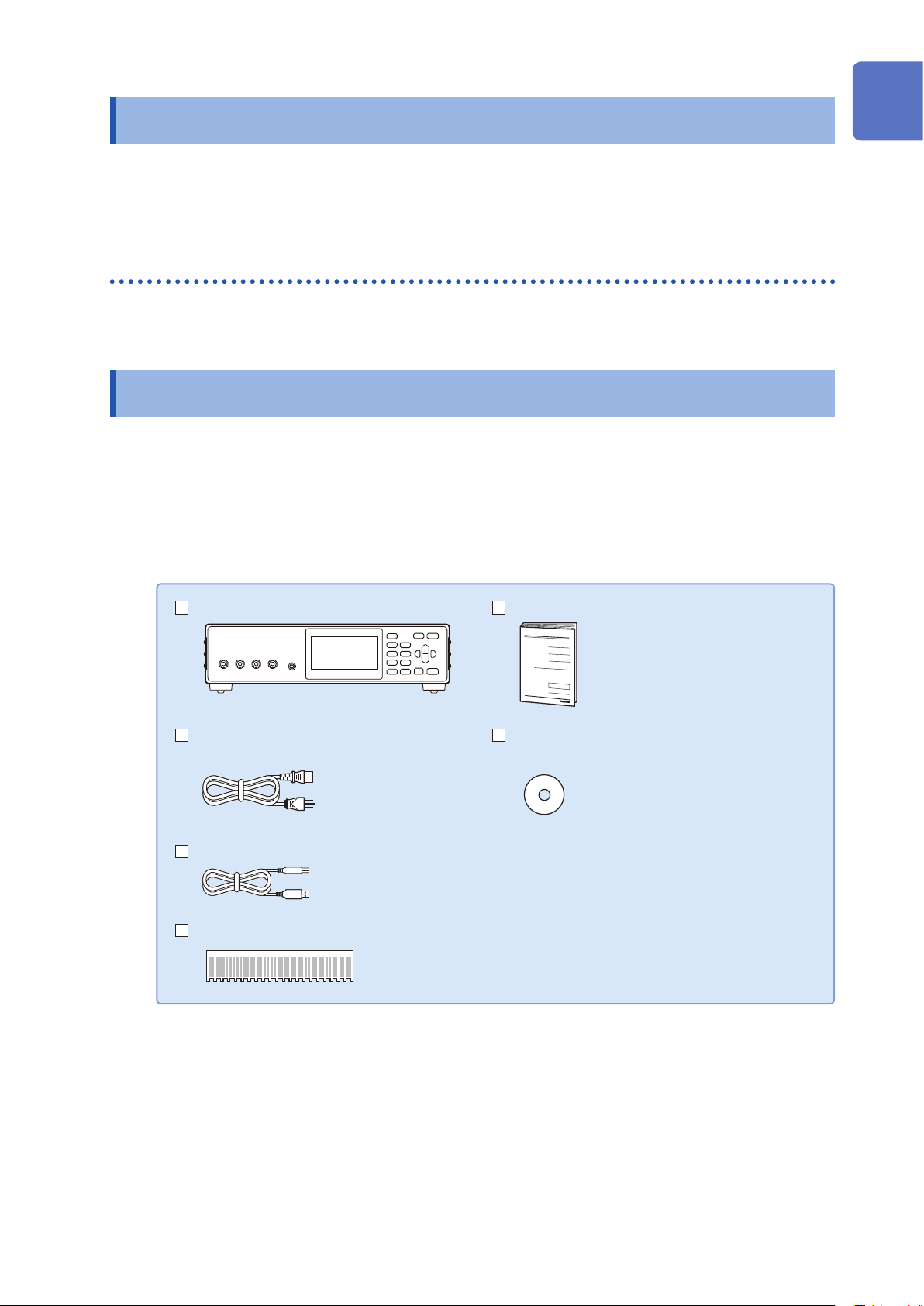
Conrm that these contents are provided.
BT4560 Battery Impedance Meter Instruction Manual
Power Cord CD (Communications Command Instruction
Manual, Application Software*, USB Driver)
2
3
4
5
6
7
USB Cable (A-B type)
Zero Adjustment Board
*The latest version can be downloaded
from our website.
8
9
10
Appx. Ind.
1
Page 8
Verifying Package Contents
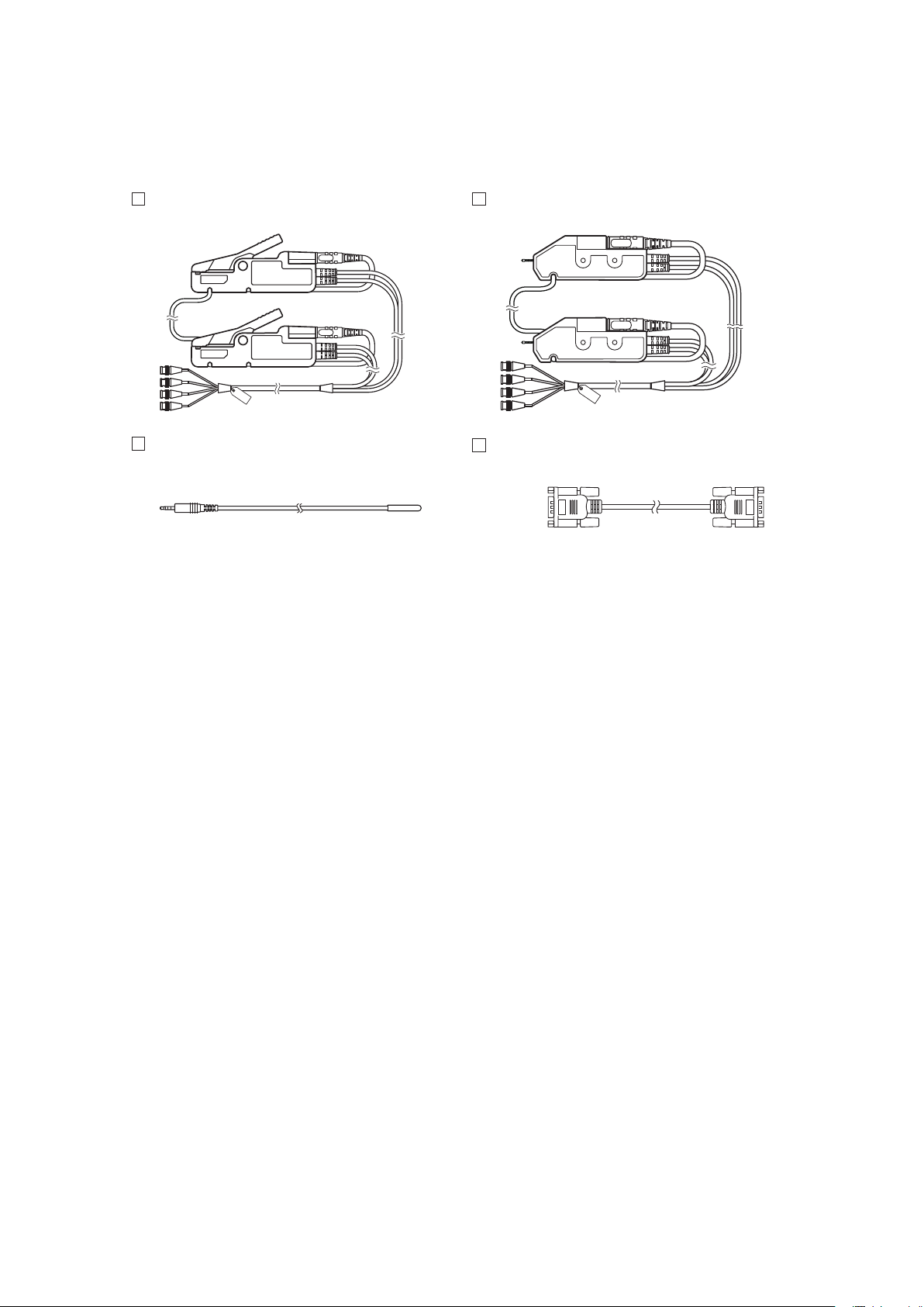
Options (p. A12)
The following options are available for the instrument. Contact your authorized Hioki distributor or
reseller when ordering.
L2002 Clip Type Probe L2003 Pin Type Probe
Z2005 Temperature Sensor
9637 RS-232C Cable (9pin-9pin/1.8 m)
2
Page 9
Safety Information
Safety Information
This instrument is designed to conform to IEC 61010 Safety Standards, and has been thoroughly
tested for safety prior to shipment. However, using the instrument in a way not described in this
manual may negate the provided safety features.
Before using the instrument, be certain to carefully read the following safety notes.
DANGER
Mishandling during use could result in injury or death, as well as damage to the
instrument. Be certain that you understand the instructions and precautions in
the manual before use.
1
2
WARNING
With regard to the electricity supply, there are risks of electric shock, heat
generation, re, and arc discharge due to short circuits. If persons unfamiliar
with electricity measuring instrument are to use the instrument, another person
familiar with such instruments must supervise operations.
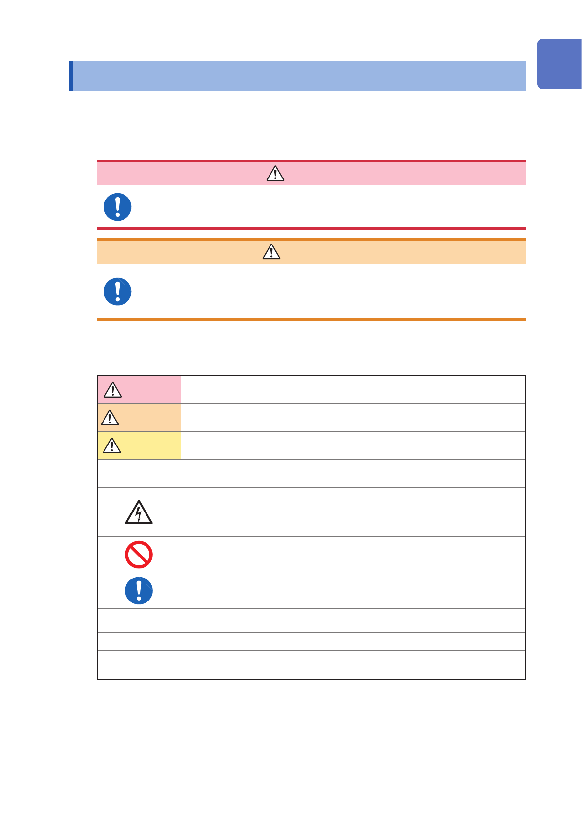
Notation
In this manual, the risk seriousness and the hazard levels are classied as follows.
DANGER
WARNING
CAUTION
IMPORTANT
Indicates an imminently hazardous situation that will result in death or serious injury to
the operator.
Indicates a potentially hazardous situation that may result in death or serious injury to
the operator.
Indicates a potentially hazardous situation that may result in minor or moderate injury
to the operator or damage to the instrument or malfunction.
Indicates information related to the operation of the instrument or maintenance tasks
with which the operators must be fully familiar.
Indicates a high voltage hazard.
If a particular safety check is not performed or the instrument is mishandled, this may
give rise to a hazardous situation; the operator may receive an electric shock, may get
burnt or may even be fatally injured.
3
4
5
6
7
8
*
[ ]
SET
(Bold character)
Indicates prohibited actions.
Indicates the action which must be performed.
Additional information is presented below.
Setting items and names on the screen are indicated in brackets [ ].
Bold characters within the text indicate operating key labels.
9
10
Appx. Ind.
3
Page 10
Safety Information
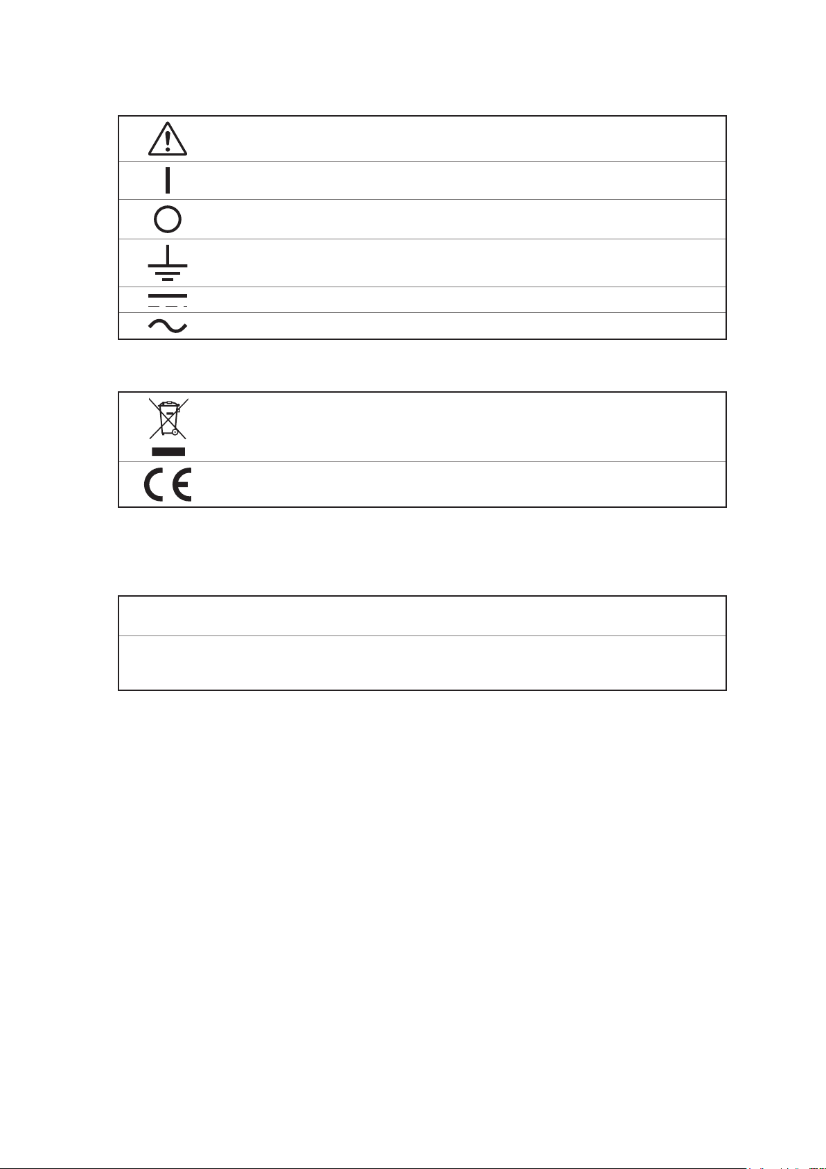
Symbols on the instrument
Indicates cautions and hazards. When the symbol is printed on the instrument, refer to a
corresponding topic in the Instruction Manual.
Indicates the ON side of the power switch.
Indicates the OFF side of the power switch.
Indicates a grounding terminal.
Indicates DC (Direct Current).
Indicates AC (Alternating Current).
Symbols for various standards
Indicates the Waste Electrical and Electronic Equipment Directive (WEEE Directive) in EU
member states.
This symbol indicates that the product conforms to regulations set out by the EC Directive.
Accuracy
We dene measurement tolerances in terms of rdg. (reading) and dgt. (digit) values, with the
following meanings:
rdg.
dgt.
(Reading or displayed value)
The value currently being measured and indicated on the measuring instrument.
(Resolution)
The smallest displayable unit on a digital measuring instrument, i.e., the input value that
causes the digital display to show a “1” as the least-signicant digit.
4
Page 11
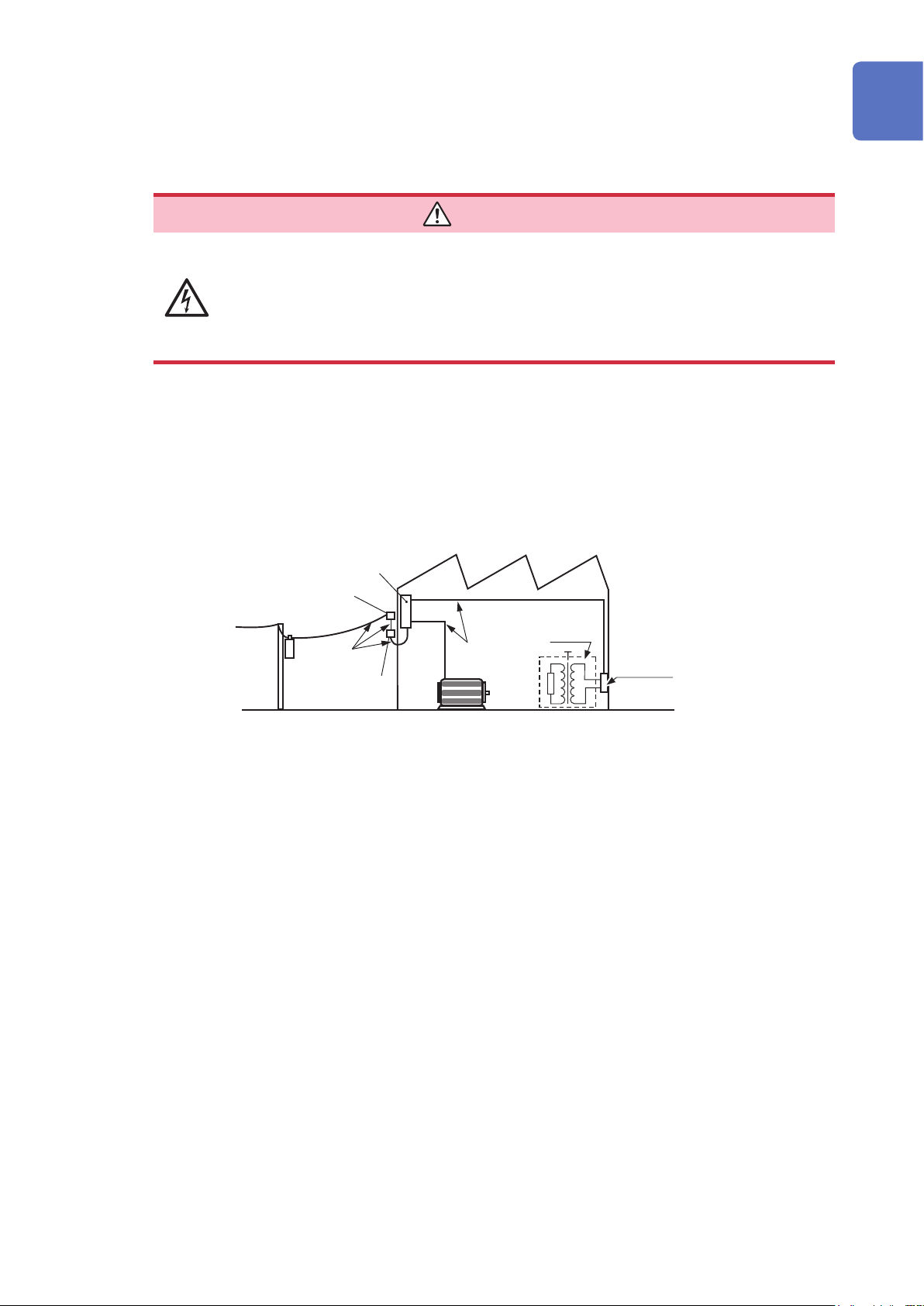
Measurement categories
To ensure safe operation of measurement instruments, IEC 61010 establishes safety standards
for various electrical environments, categorized as CAT II to CAT IV, and called measurement
categories.
Safety Information
DANGER
• Using a measuring instrument in an environment designated with a higher-
numbered category than that for which the instrument is rated could result in a
severe accident, and must be carefully avoided.
• Using a measuring instrument without categories in an environment designated
with the CAT II to CAT IV category could result in a severe accident, and must
be carefully avoided.
CAT II: When directly measuring the electrical outlet receptacles of the primary electrical
circuits in equipment connected to an AC electrical outlet by a power cord (portable
tools, household appliances, etc.).
CAT III: When measuring the primary electrical circuits of heavy equipment (xed installations)
connected directly to the distribution panel, and feeders from the distribution panel to
outlets.
CAT IV: When measuring the circuit from the service drop to the service entrance, and to the
power meter and primary overcurrent protection device (distribution panel).
Distribution Panel
Service Entrance
Service Drop
CAT IV
Power Meter
Internal Wiring
CAT II
CAT III
Outlet
1
2
3
4
5
6
Fixed Installation
7
8
9
10
Appx. Ind.
5
Page 12
Operating Precautions
Operating Precautions
Follow these precautions to ensure safe operation and to obtain the full benets of the various
functions.
DANGER
This instrument carries a maximum electric current up to 1.5 A to the measuring
object. Do not measure the primary battery. Doing so may cause damage to the
measuring object.
Battery may cause ignition and damage due to overcharge/over discharge. Be
certain in managing battery voltage when measuring.
WARNING
If the measurement probe or the instrument is damaged, there is a risk of electric
shock. Before using the instrument, perform the following inspection.
• Before using the instrument, check that the coating of the measurement
probes are neither ripped nor torn and that no metal parts of connection cord
are exposed. Using the instrument under such conditions could result in
electrocution. Replace the measurement probes with those specied by our
company.
• Before using the instrument for the rst time, verify that it operates normally
to ensure that no damage occurred during storage or shipping. If you nd any
damage, contact your authorized Hioki distributor or reseller.
Instrument installation
Installing the instrument in inappropriate locations may cause a malfunction of instrument or may
give rise to an accident. Avoid the following locations.
For details on the operating temperature and humidity, see the specications p. 115.
WARNING
• Exposed to direct sunlight or high temperature
• Exposed to corrosive or combustible gases
• Exposed to water, oil, chemicals, or solvents
• Exposed to high humidity or condensation
• Exposed to a strong electromagnetic eld or electrostatic charge
• Exposed to high quantities of dust particles
• Near induction heating systems (such as high-frequency induction heating systems
and IH cooking equipment)
• Susceptible to vibration
6
Page 13
Operating Precautions
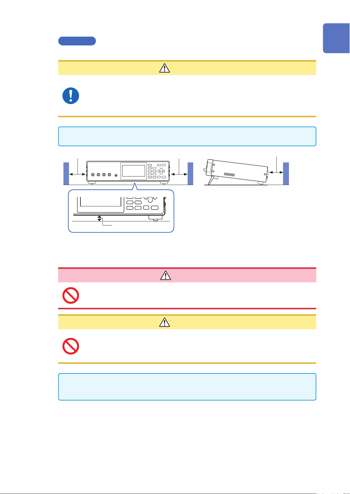
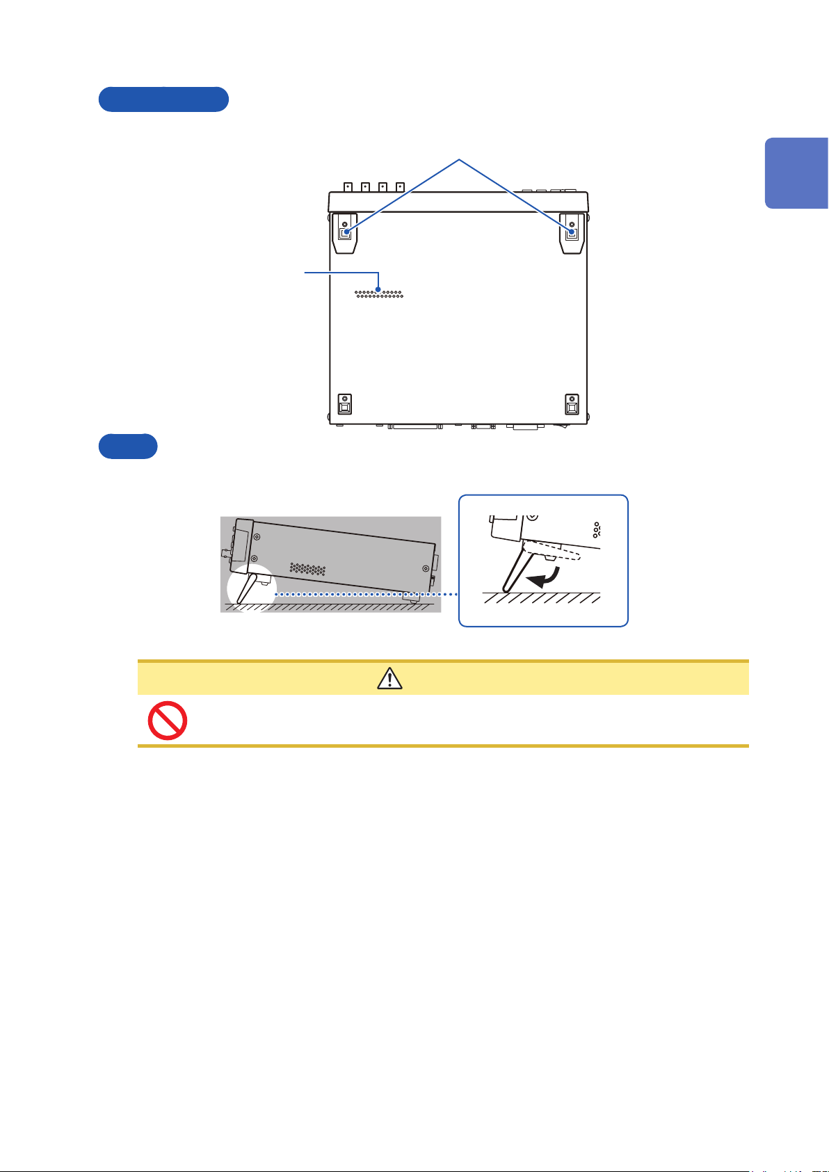
Installation
To prevent overheating, be sure to leave the specied clearances around the instrument.
CAUTION
• Do not install the instrument with any side except the bottom facing down.
• Ventilation holes for heat radiation are provided on the side, bottom and rear panels
of the instrument. Leave sufcient space around the ventilation holes and install
the instrument with the holes unobstructed. Installation of the instrument with the
ventilation holes obstructed may cause a malfunction or re.
Unplugging the power cord kills power to the instrument. Be sure to provide enough unobstructed
space to unplug the power cord immediately in an emergency.
Greater than 50 mmGreater than 50 mm
Greater than 10 mm
Rear
1
2
3
4
Greater than 15 mm
“Raising/closing the stand” (p. 13)
Handling the instrument
To avoid electric shock, do not remove the instrument’s case. The internal
components of the instrument carry high voltages and may become very hot
during operation.
• Do not place the instrument on an unstable table or an inclined place. Dropping or
knocking down the instrument can cause injury or damage to the instrument.
• To avoid damage to the instrument, protect it from physical shock when transporting
and handling. Be especially careful to avoid physical shock from dropping.
This instrument may cause interference if used in residential areas. Such use must be avoided
unless the user takes special measures to reduce electromagnetic emissions to prevent
interference to the reception of radio and television broadcasts.
DANGER
CAUTION
5
6
7
8
9
10
Appx. Ind.
7
Page 14
Operating Precautions
Before connecting the power cord
• Before turning the instrument on, make sure the supply voltage matches that
indicated on its power connector. Connection to an improper supply voltage
may damage the instrument and present an electrical hazard.
• To avoid electrical accidents and to maintain the safety specications of this
instrument, connect the power cord provided only to a 3-contact (two-conductor
+ ground) outlet.
• To avoid damaging the power cord, grasp the plug, not the cord, when unplugging it
from the power outlet.
• Avoid using an uninterruptible power supply (UPS) or DC/AC inverter with rectangular
wave or pseudo-sine-wave output to power the instrument. Doing so may damage the
instrument.
WARNING
CAUTION
IMPORTANT
• Turn off the power before disconnecting the power cord.
• Use only the specied power cord. Using a non-specied cord may result in incorrect
measurements due to poor connection or other reasons.
Before connecting measurement probe/temperature sensor
DANGER
• To avoid electrical hazards and damage to the instrument, do not apply voltage
exceeding the rated maximum to the input terminals.
• The maximum rated voltage to earth of the SOURCE-H terminal and the
SENSE-H terminal is ±5 V DC. The maximum rated voltage to earth of the
SOURCE-L terminal and the SENSE-L terminal is 0 V DC. Attempting to measure
voltages exceeding this level with respect to ground could damage the
instrument and result in personal injury. (Do not apply voltage to earth since the
SOURCE-L terminal and SENSE-L terminal where pseudo earthing is provided
in the internal circuit.)
• To avoid electrical shock, be careful to avoid shorting live lines with the
measurement probe.
WARNING
To avoid injury or damage to the instrument, do not attempt to measure AC
voltage, or DC voltage exceeding 5 V DC.
8
Page 15
Operating Precautions
CAUTION
• To avoid damage to the instrument, do not apply voltage or current to temperature
sensor terminal.
• To prevent cable damage, do not step on cables or pinch them between other objects.
Do not bend or pull on cables at their base.
• The sensor used in the temperature sensor is a thin, precision platinum lm. Be aware
that excessive voltage pulses or static discharges can destroy the lm.
• Avoid subjecting the temperature sensor tip to physical shock, and avoid sharp bends
in the sensor. These may damage the probe or break a wire.
• When measuring high temperatures, do not let the temperature sensor exceed the
specied temperature range.
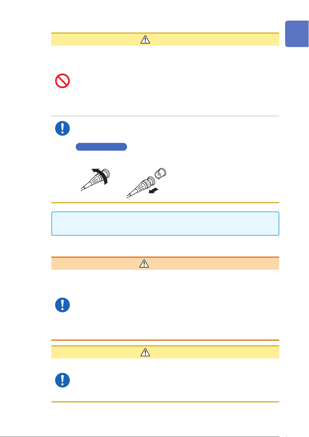
• When disconnecting the BNC connector, be sure to release the lock before pulling off
the connector. Forcibly pulling the connector without releasing the lock, or pulling on
the cable, can damage the connector.
Releasing the lock
1
2
3
1 2
Use only the specied measurement probe and the temperature sensor. Using a non-specied
one when measuring may result in incorrect measurements due to poor connection or other
reasons.
Before connecting the communication cable
WARNING
• Always turn both devices OFF when connecting and disconnecting an interface
connector. Otherwise, an electric shock accident may occur.
• After connecting, be sure to tighten the screws. When the mounting screws
are not rmly tightened, the input module may not perform to specications, or
may even fail.
• To avoid electric shock or damage to the equipment, always observe the
following precautions when connecting to connectors.
• Be careful to avoid exceeding the ratings of connectors .
• During operation, a wire becoming dislocated and contacting another
conductive object can be serious hazard. Use screws to secure RS-232C.
4
5
6
7
8
9
CAUTION
The USB and RS-232C are not insulated to the ground (earth). Grounding (earthing) for
the instrument and the controller must be wired as the common earth. Different earthing
may cause a voltage potential difference between the GNDs of the instrument and the
controller. Connecting the communication cable under condition that there is a voltage
potential difference may cause a malfunction and/or a failure. When different earthing is
required, connecting instruments and devices must be isolated.
10
Appx. Ind.
9
Page 16
Operating Precautions
Before switching the current sink (NPN) and the current source (PNP)
CAUTION
You must not operate the EXT.I/O MODE changing over switch (NPN/PNP) during
Power-ON status of the instrument.
Set the NPN/PNP based on devices that are externally connected.
Before connecting the EXT.I/O terminals
WARNING
• The EXT.I/O of the instrument cannot be applied to from an external power. Do
not apply external power to the instrument. (The ISO_5V terminal of the EXT I/O
connector is a 5 V (NPN)/-5 V (PNP) power output.)
To avoid electric shock or damage to the instrument, always observe the
following precautions when connecting to the connector.
• Always turn off the main power switch to the instrument and to any device to be
connected before making connections.
• Be careful to avoid exceeding the ratings of the signal of the EXT.I/O terminals.
(p. 111)
During operation, a wire becoming dislocated and contacting another
conductive object can be serious hazard. Use screws to secure the external
connectors.
Precautions during shipment
When shipping the instrument, observe the following.
Hioki cannot be responsible for damage that occurs during shipment.
CAUTION
During shipment of the instrument, handle it carefully so that it is not damaged due to a
vibration or shock.
CD disc precautions
IMPORTANT
• Exercise care to keep the recorded side of discs free of dirt and scratches. When writing text
on a disc’s label, use a pen or marker with a soft tip.
• Keep discs inside a protective case and do not expose to direct sunlight, high temperature, or
high humidity.
• Hioki is not liable for any issues your computer system experiences in the course of using this
disc.
10
Page 17

1
Overview
1.1 Product Overview and Features
The BT4560 is a variable-frequency impedance meter.
This instrument is equipped with a highly accurate voltmeter and a temperature measurement function,
and optimal for quality control of batteries.
This instrument has the circuit conguration with high noise immunity, and thus, can provide stable
measurement even at production sites.
• The instrument can measure the internal impedance of a battery using
the AC four-terminal method.
What can the instrument
BT4560 measure?
What is the difference
between the instrument BT4560
and the existing battery impedance
instruments?
(Frequency: 0.1 Hz to 1050 Hz, Minimum resolution: 0.1 µ
• This instrument can also measure the DC voltage (the electromotive
force of the battery) simultaneously.
(Resolution: 10 µV, Measurement accuracy: ±0.0035% rdg.±5 dgt.)
• In addition, temperature measurement, which is important for battery
control, can be performed. (Temperature measurement accuracy:
±0.5°C)
• The instrument has a simple structure, which does not need a loading
device. It is not necessary to congure a system.
• This is a compact instrument and measurement can be performed
without other instruments or devices.
)
Ω
1
Overview
Can the instrument BT4560 be
used at production lines or sites?
Can the instrument BT4560
analyze the internal resistance of
batteries?
• Optional measurement probes can be extended up to a maximum of
4 m, corresponding to an operating environment.
• This can provide highly accurate measurement with a measurement
conguration that resists the inuences of external noise and contact
resistance.
• The built-in comparator function can perform quality judgment of
batteries.
• PLC control using the EXT. I/O is possible.
• A personal computer with application software connected to the
instrument can continuously measure any frequency in the range of
0.01 Hz to 1050 Hz and necessary points.
• This instrument is able to draw Cole-Cole plots*.
* The Cole-Cole plot is a plot of the frequency characteristics of battery
impedance in which the horizontal axis represents the real part of
impedance and the vertical axis represents the imaginary part of
impedance. This plot is used to evaluate the internal resistance of the
battery.
11
Page 18
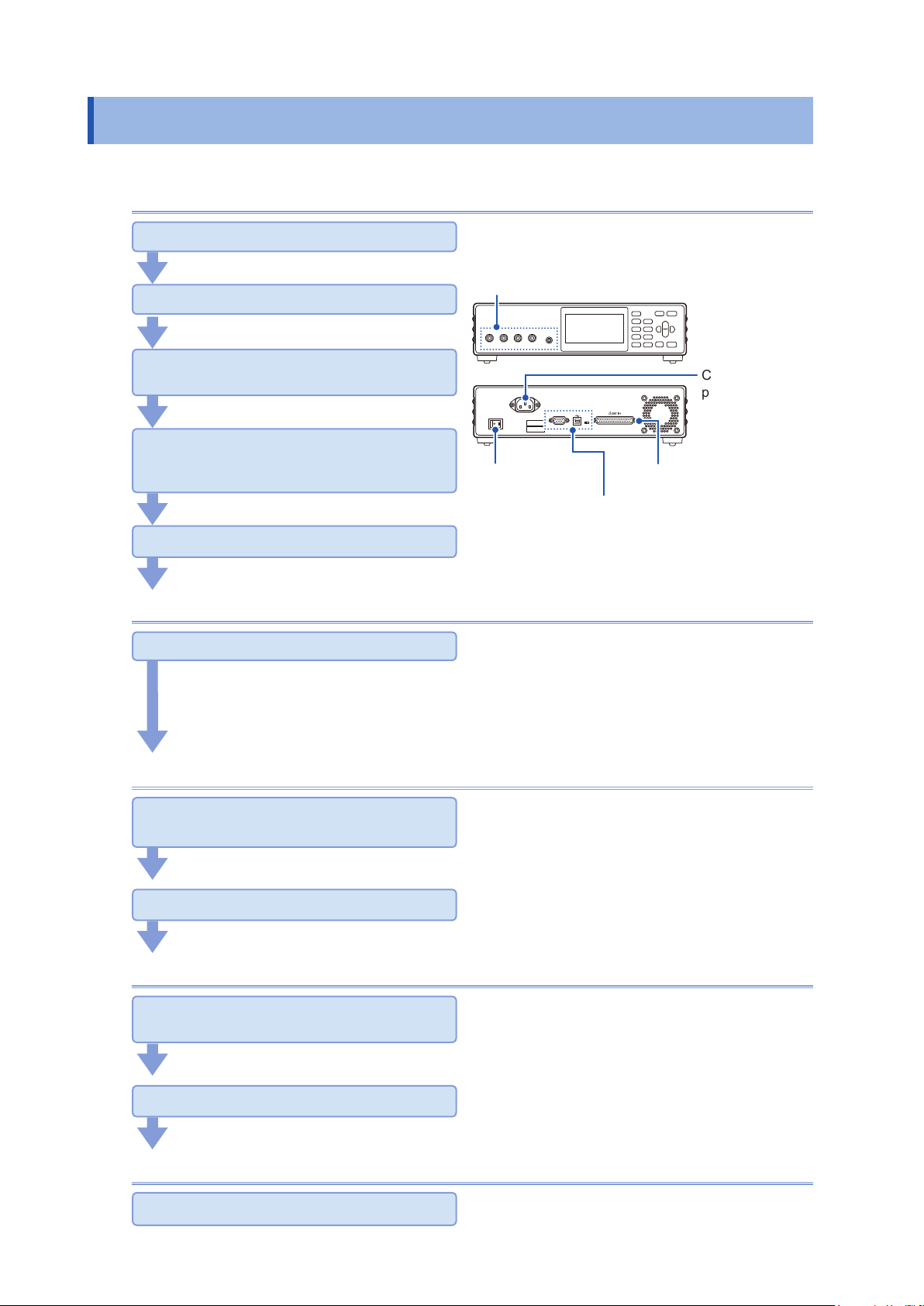
Names and Functions of Parts
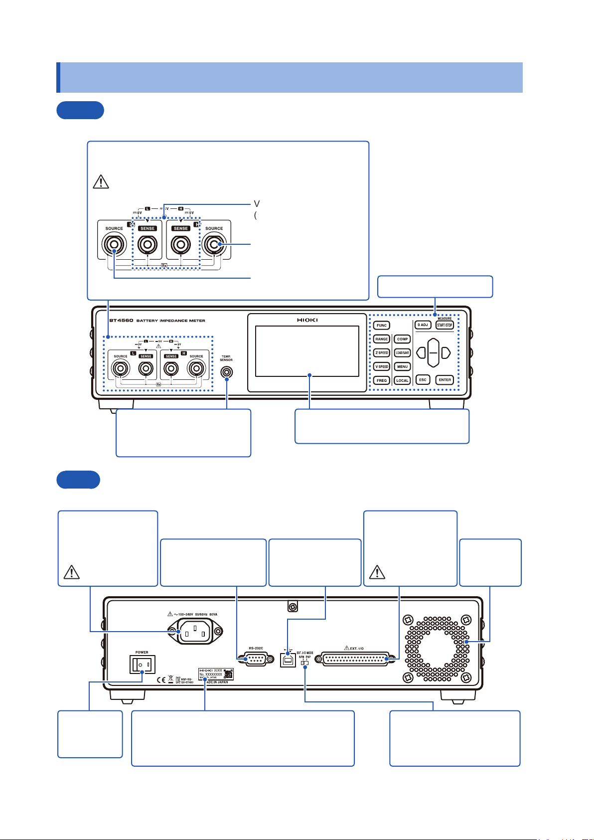
1.2 Names and Functions of Parts
Front
Measurement terminal
Connect the measurement probe.
Refer to p. 8.
Voltage detection terminal
(SENSE-L, SENSE-H)
Current generation terminal
(SOURCE-H)
Temperature sensor terminal
Connects the Z2005
temperature sensor.
Rear
Power inlet
Connects the power
cord (accessory).
(p. 17)
Refer to p. 8.
RS-232C interface
Connects to the
computer. (p. 95)
Current detection terminal
(SOURCE-L)
Display
Monochrome graphic LCD
USB interface
Connects to the
computer. (p. 95)
Operating keys (p. 14)
EXT.I/O terminal
Connects to an
external controller.
(p. 79)
Refer to p. 10.
Vents
Keep clear of
obstructions .
Power
switch
(p. 19)
12
Manufacturer’s serial number
Indicates the serial number.
Do not remove this label, as it is required for product
support.
EXT.I/O NPN/PNP switch
Left: Current sink (NPN)
Right: Current source (PNP)
(p. 80)
Page 19
Bottom panel
Names and Functions of Parts
Stands
1
Overview
Vents
Side
Raising/closing the stand
Do not apply heavy downward pressure with the stand extended. The stand could be
damaged.
CAUTION
13
Page 20
Names and Functions of Parts
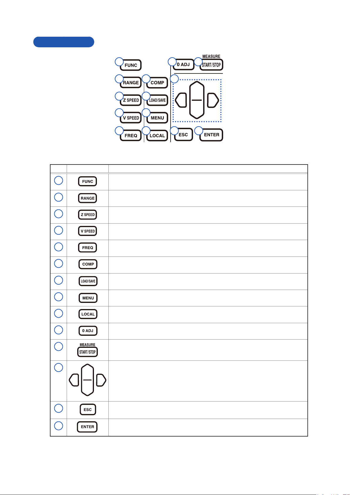
Operating keys
1
2
3
4
5
Key Description
1
2
3
4
Selects the measurement function (combination of the voltage measurement and
the impedance measurement).
Sets the measurement range.
Sets the measurement speed of impedance.
Sets the measurement speed of voltage.
6
7
8
9
10 11
12
13 14
10
11
12
13
5
6
7
8
9
Sets the measurement frequency of impedance.
Sets the power switch of ON-OFF and the upper and lower limit values ,etc. of the
comparator.
Saves and reads the measurement conditions.
Sets each of the functions (Trigger, Sample delay, Self-calibration, etc.).
Releases the remote state and enables key operation.
Performs the zero adjustment.
Starts and stops the measurement.
• Moves setting items and digits.
• Changes numerical values.
• Cancels the settings being set.
• Erases a display message.
14
14
Conrms the setting.
Page 21

Screen Conguration and Operation
1.3 Screen Conguration and Operation
The instrument is congured with the measurement screen and each setting screen.
Measurement screen
Settings screen
Measurement frequency setting screen
Comparator setting screen
1
Overview
When [EXIT] is selected, display returns to the
measurement screen.
Panel load/panel save screen
Menu settings screen
Zero adjustment setting screen
When [EXIT] is selected, display returns to the
measurement screen.
When [EXIT] is selected, display returns to the
measurement screen.
15
Page 22
Measurement Flow
1.4 Measurement Flow
Be sure to refer to “Operating Precautions” (p. 6) before using the instrument.
Installing, connecting, and turning power on
Install (p. 7).
Connect the measurement probe and the temperature
sensor (p. 18).
Connect the power cord (p. 17).
Connect the measurement probe and the
temperature sensor (p. 18).
Connect the external interface (as needed).
• Use the EXT. I/O (p. 80).
• Communicate computer with USB or RS-232C (p. 95).
Turn Power On (p. 19).
Setting the instrument (p. 21)
Set the measurement conditions (as needed).
• Basic setting (p. 21)
• Setting basic conditions for customization (p. 37)
• Setting system related items (p. 63)
• Initial setting table (p. 76)
Performing the zero adjustment
Make the measurement probes short-circuit
with the zero adjustment board (p. 26).
Turn Power On
(p. 19).
Communicate computer with
USB or RS-232C (p. 95).
Connect the
power cord
(p. 17).
Use the EXT. I/O (p. 79).
Perform zero adjustment (p. 26).
Starting the measurement
Connect the measurement probe to the
object being measured.
(For EXT trigger, start the measurement by pressing the START/STOP key.)
Check the measurement values.
Ending
Turn Power Off (p. 19).
16
Page 23
2
Preparation
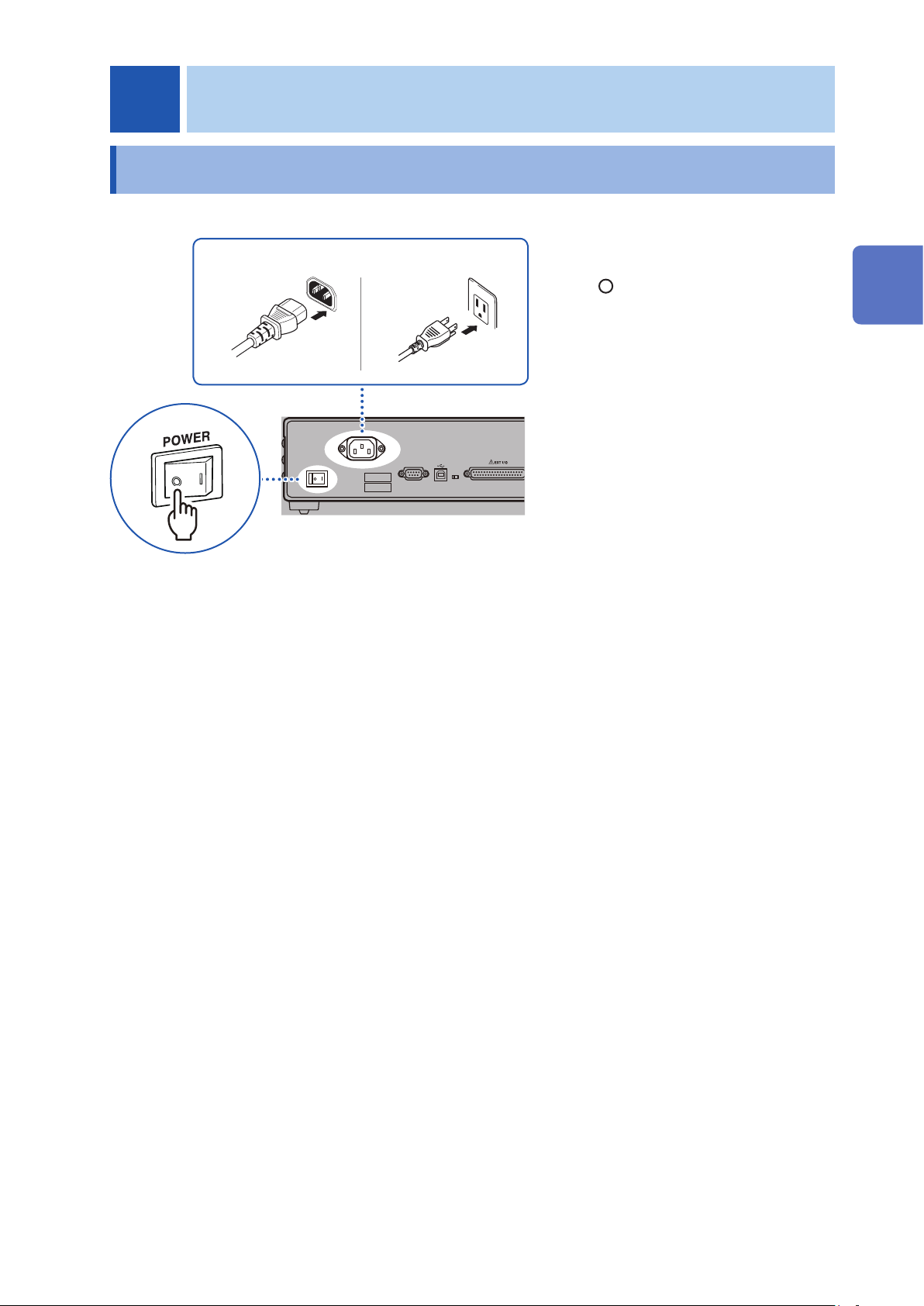
2.1 Connecting the Power Cord
Power inlet Outlet
2 3
1
Check that the power switch
1
(rear) of the instrument is OFF
( ).
Check that the power voltage
2
is in the range indicated on the
rear, and then connect the power
cord to the power inlet.
Connect the plug of the power
3
cord into an outlet.
2
Preparation
17
Page 24
Connecting the Measurement Probe and Temperature Sensor (Optional)
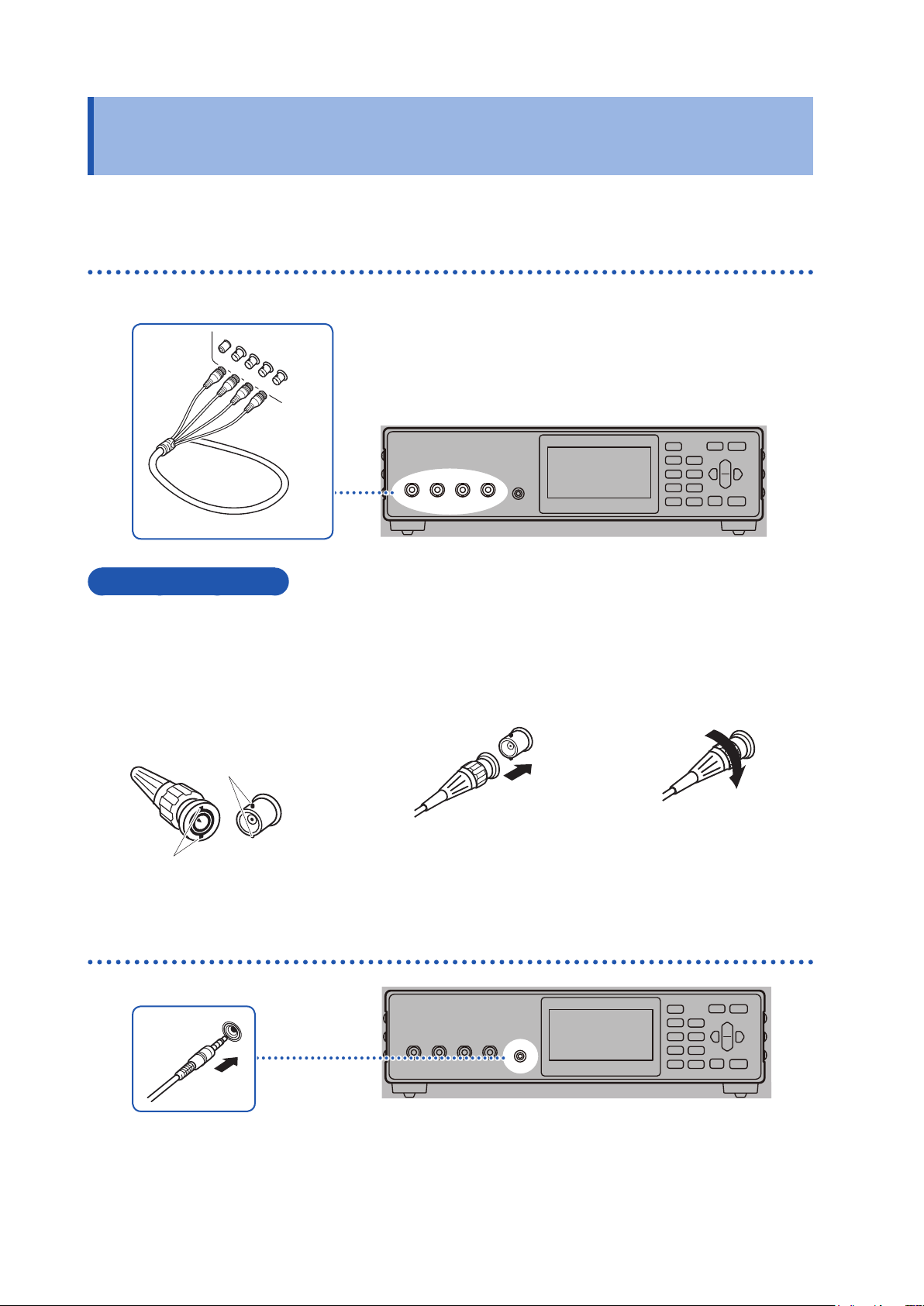
2.2 Connecting the Measurement Probe and Temperature Sensor (Optional)
The measurement probe and the temperature sensor are optional. (p. A12)
Connect the four-terminal cable to the instrument
Connection method
Check the orientation of the groove
1
in the BNC connector and ensure
that it ts into the connector guide
of the instrument side.
Connector guide of the
instrument’s current
input terminal
BNC connector groove of
measurement probe
Align the groove in the BNC
2
connector along the connector
guide of the instrument, and
insert the BNC connector into the
instrument connector.
3
Connect the temperature sensor to the instrument
Turn the BNC connector to the
right and lock it.
18
Page 25
Turning the Power ON or OFF
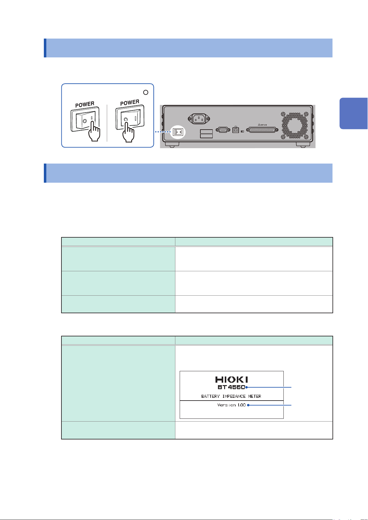
2.3 Turning the Power ON or OFF
Turn the power on or off using the power switch on the rear.
Power OFF ( )Power ON (I)
2.4 Inspection Before Use
Before using the instrument, verify that it operates normally to ensure that no damage occurred
during storage or shipping. If you nd any damage, contact your authorized Hioki distributor or
reseller.
2
Preparation
Verifying the instrument and the peripheral devices
Inspection items Countermeasures
Is the power cord insulation torn, or is any
metal exposed?
Is the insulation of the measurement probe
or the connection cords torn, or is any metal
exposed?
Is the instrument damaged? When any damage is found, it may cause electrical shock. Do
Verifying when turning the power on
Inspection items Countermeasures
Does the fan rotate when the power is
turned on? Are there the indications of
“BT4560” and “Version number” on the
display?
Do not use the instrument if damage is found, as electric
shock or short-circuit accidents could result.
Contact your authorized Hioki distributor or reseller.
When any damage is found, it may cause electrical shock. If
this happens, replace the measurement probe or connection
cords with ones specied by Hioki.
not use the instrument, and then request repair.
If the fan does not rotate, or if “BT4560” and “Version number”
are not displayed, the instrument may be malfunctioning.
Request repairs.
BT4560
After the self-test, is the measurement
screen displayed?
Version
If the screen does not display, the instrument may have be
malfunctioning internally. Request repairs.
19
Page 26

Inspection Before Use
20
Page 27

3
Basic Measurement
3.1 Selecting the Measurement Functions
Set the measurement functions.
Parameters
Z
θ
R
By pressing
For the selectable functions, refer to Table below.
Measurement functions
R, X, V, T
Measurement items
Impedance
Phase angle
Resistance
(FUNC) the measurement functions are switched.
Resistance
measurement value
Reactance
measurement value
Voltage
measurement value
Parameters
X
V
T
Screen
Measurement items
Reactance
Voltage
Temperature
RXVT
ZθVT
RXT
Measurement
functions switches.
VT
ZθT
Temperature
3
Basic Measurement
Z, θ, V, T
R, X, T
Z, θ, T
V, T
measurement value
Impedance
Phase angle
measurement value
Voltage
measurement value
Resistance
measurement value
Reactance
measurement value
Impedance
measurement value
Phase angle
measurement value
Voltage measurement
value
Temperature
Temperature
Temperature
Temperature
21
Page 28
Selecting the Measurement Range
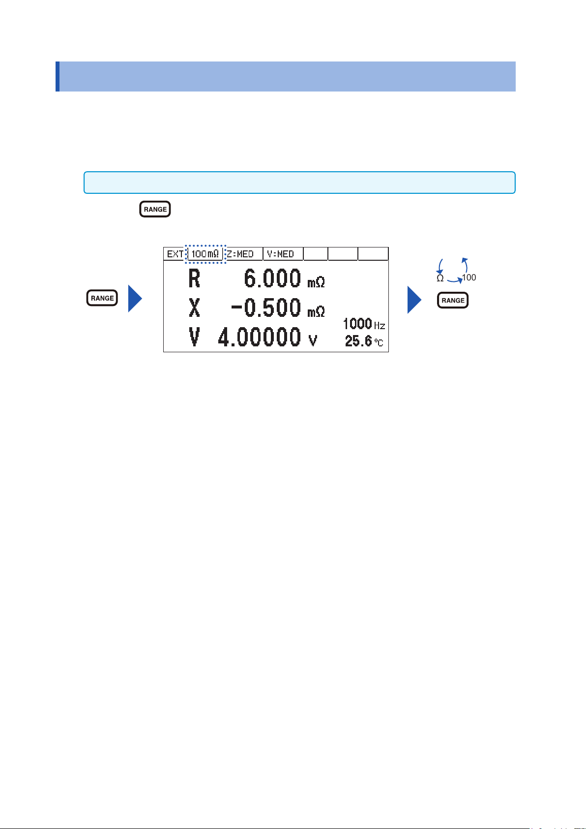
3.2 Selecting the Measurement Range
Set the measurement range of impedance (3 mΩ, 10 mΩ, 100 mΩ).
The voltage and the temperature have a single range respectively. Thus, setting is not necessary.
Use the measurement range of impedance when the impedance measurement value exceeds the
present range or when changing the measurement accuracy.
When the functions (V, T) are selected, setting cannot be performed.
By pressing (RANGE) the measurement ranges are switched.
3 m
10 m
Ω
Ω
100 m
Ω
Measurement ranges
switches.
22
Page 29
Setting the Measurement Speed
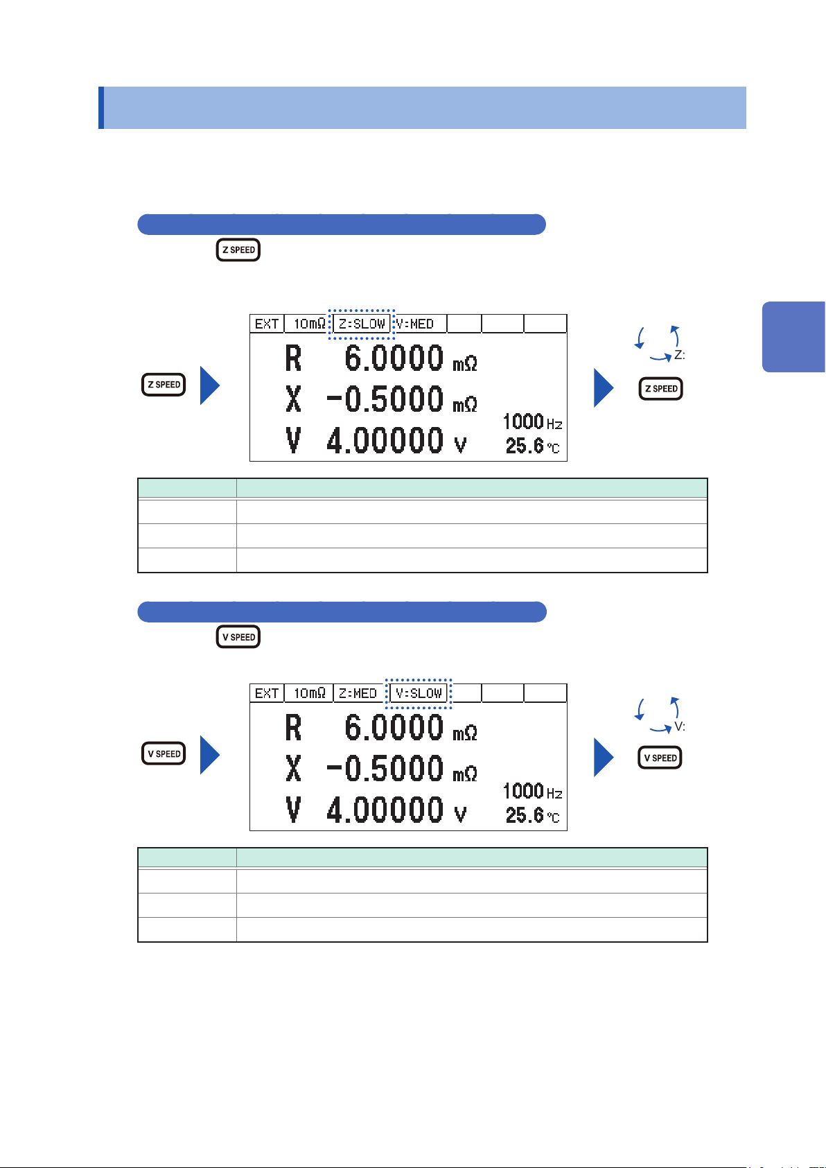
3.3 Setting the Measurement Speed
Set the measurement speed (FAST, MED, SLOW) in the impedance measurement and the voltage
measurement.
The slower the measurement speed is, the more accurate are the results.
Set the measurement speed of impedance measurement (Z)
By pressing
switched.
Setting Items Contents
Z:FAST When the high speed measurement is performed, set this item.
Z:MED When the normal speed measurement is performed, set this item.
Z:SLOW When the high accurate measurement is performed, set this item.
Set the measurement speed in the voltage measurement (V)
By pressing
(Z SPEED) the measurement speed in the impedance measurement is
(V SPEED) the measurement speed in the voltage measurement is switched.
Z:FAST
Z:MED
Measurement speed
Z:SLOW
switches.
3
Basic Measurement
V:MED
Measurement speed
Setting Items Contents
V:FAST When the high speed measurement is performed, set this item.
V:MED When the normal speed measurement is performed, set this item.
V:SLOW When the high accurate measurement is performed, set this item.
V:FAST
V:SLOW
switches.
23
Page 30
Setting the Measurement Frequency
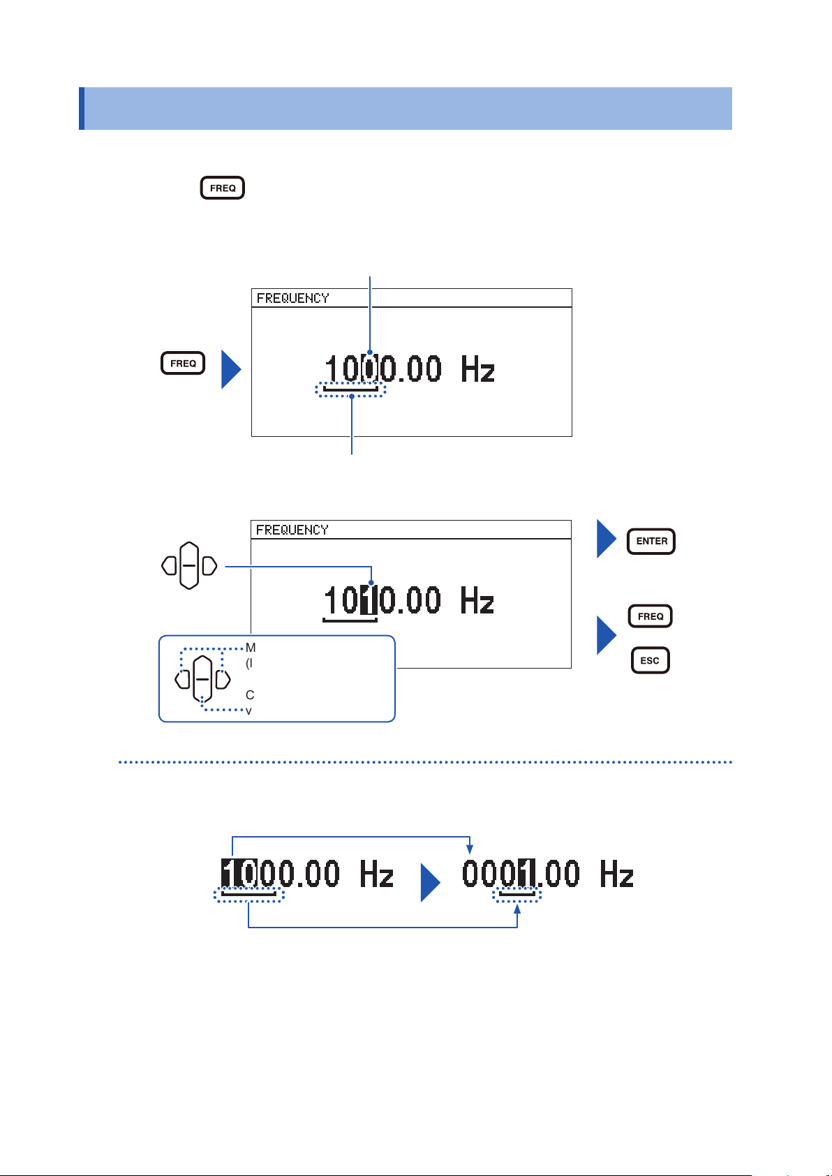
3.4 Setting the Measurement Frequency
Setting the measurement frequency. (0.1 Hz to 1050 Hz)
Press (FREQ). (Measurement frequency setting screen appears.)
1
The selected digit is displayed in reverse black and white, with a bar under the digit enabled
to be set.
Portion selected (reverse black and white)
Digits enabled to be set
Set the measurement frequency.
2
Setting
Move to the next digit
(left or right)
Changing the numerical
value (up and down)
Disabled digits will be set to zero automatically.
Conrm
(or)
Cancel
The display will automatically change
to zero as setting the digits is disabled.
24
Page 31

Setting the Measurement Frequency
When the measurement time is long (Display of the Progress Bar)
When the impedance measurement time is long (more than approx. 1 second), the progress bar is
displayed on the right side of the measuring screen which is in operation.
During sample delay (p. 38)
[D] is displayed at the center of the progress bar.
Progress bar
([D] is displayed at the center.)
During impedance measurement
Percentage of measurement progress is displayed at the center of the progress bar.
3
Basic Measurement
Progress bar
(Progress percentage is displayed at the
center.)
Transition of the progress percentage
Progress
percentage
0%
During the detection of zero cross stop (When zero cross stop is ON) (p. 47)
[Z] is displayed at the center of the progress bar.
Progress
percentage
20%
Progress
percentage
80%
Measurement complete (The
progress percentage is 100%.)
The measurement is nished and the
measurement value is displayed.
Progress bar
([Z] is displayed at the center.)
25
Page 32

Performing the Zero Adjustment
3.5 Performing the Zero Adjustment
Remove the residual components due to offset and the measurement environment.
Be sure to perform the zero adjustment before the impedance measurement and the voltage
measurement.
Performing the zero adjustment
Placing the measurement probe (Example: L2002)
Place the measurement probe in the same condition as the measurement is performed.
1
The zero residual volume differs due to the condition of the measurement probe (length, shape, and location).
Thus, place the measurement probe in the same condition as the actual measurement is performed, before
performing the zero adjustment.
Prepare the zero adjustment board (accessory).
2
Place the probes with a space the same length as the width of the actual measuring object.
3
Clip a pattern on the zero adjustment board, with the same number of divisions for both HIGH and LOW.
L2002
Clip Type Probe
Zero adjustment board
Measuring object
Divisions
Setting the zero adjustment
There are two methods of the zero adjustment, the spot zero adjustment (SPOT) and the all zero
adjustment (ALL).
The zero adjustments for the range and the frequency that are presently set, and
the voltage measurement are performed. The time required differs according to
Spot zero adjustment
(SPOT)
All zero adjustment
(ALL)
the frequency. The lower the frequency, the longer it takes to set (Reference:
approx. 350 s for 0.1 Hz, approx. 45 s for 1 Hz).
When setting at a different range and/or frequency, zero adjustment will be
invalid.
The zero adjustments for the range that is presently set, and the full range
of the frequency, and the voltage measurement are performed. Even if the
measurement frequency is changed, the zero adjustment is effective. However,
when the range is changed, the zero adjustment is not effective.
26
• When the zero adjustment is effective, the indicator of 0 ADJ appears on the measurement
screen.
• After performing the zero adjustment, even if the zero adjustment becomes ineffective, the zero
adjustment will become effective when returning to the conditions that the zero adjustment was
performed.
• With the 0ADJ_SPOT of the EXT.I/O and 0ADJ_ALL terminals, performing can be done.
Page 33

Press (0 ADJ). (The zero adjustment screen appears.)
1
Select [ON].
2
Performing the Zero Adjustment
3
Selection
Select [SPOT] or [ALL].
3
Selection
When selecting [ALL], the conrmation window opens.
OK: Performing all zero adjustment
CANCEL: Returns to the measurement screen without execution.
To the SPOT and ALL
selection screen
(or)
Cancel
Performing zero
adjustment
(or)
Cancel
Basic Measurement
Conrm
Selection
After the zero adjustment is normally performed, the screen will go back to the measurement
4
screen.
(When the zero adjustment is effective, 0 ADJ appears at the upper right on the measurement
screen.)
27
Page 34

Performing the Zero Adjustment
When the zero adjustment is not normally performed
When [0 ADJUST ERROR] appears, the proper adjustment is not performed.
Check the short-circuit method of the measurement probe and perform the zero adjustment with a proper
method so that the zero adjustment data values come within the range given in the table below.
Return
Impedance
measurement
range -0.1000 mΩ to 0.1000 m
3 m
Ω
10 mΩ range -0.3000 mΩ to 0.3000 m
100 mΩ range -3.000 mΩ to 3.000 m
Voltage measurement
-0.10000 V to 0.10000 V
R X
-1.5000 mΩ to 1.5000 m
Ω
-1.5000 mΩ to 1.5000 m
Ω
Ω
-1.500 mΩ to 1.500 m
Ω
Ω
Ω
Disabling zero adjustment
Select [OFF] on the zero adjustment screen.
(When [OFF] is selected, zero adjustment will be disabled. To enable, perform zero adjustment again.)
Conrm
28
Selection
(or)
Cancel
Page 35

When measuring while changing the measurement range
If measured as below, zero adjustment will not be necessary every time the range is changed.
1. Perform zero adjustment at 3 mΩ range.
2. Save the current condition by panel saving function (p. 58).
(Zero adjustment data of the current range will be saved.)
3. Change the range to 10 m
4. Save the current condition by panel saving function (p. 58).
5. Change the range to 100 m
6. Save the current condition by panel saving function (p. 58).
7. Read the condition of the range used by panel saving function (p. 58), and then measure.
and perform zero adjustment.
Ω
and perform zero adjustment.
Ω
Connection when performing the zero adjustment
Performing the Zero Adjustment
If the zero adjustment board is used, the connection will be as below.
Perform zero adjustment with the same connection when making your own measurement probe (refer to
“Appx. 3 Cautions When Making Your Own Measurement Probe” (p. A4)).
Connect the shields of SOURCE-H and SOURCE-L.
1
(Connected by the return cable)
Connect SENSE-H and SENSE-L.
2
Connect SOURCE-H and SOURCE-L.
3
Connect the above 2 and 3 lines at one point.
4
SENSE-HSENSE-L SOURCE-HSOURCE-L
3
Basic Measurement
Connection to the SOURCE shield Connect the above 2 and 3 at one point.
Connection to the
SOURCE shield
29
Page 36

Checking the Measurement Results
3.6 Checking the Measurement Results
Detecting the measurement abnormality
When the measurement is not normally performed, the indication expressing the measurement
abnormality appears on the screen, and the ERR signal from the EXT.I/O is output.
Contact error
When the resistance value is greater between SOURCE-H and SENSE-H, or between SENSE-L
and SOURCE-L, the contact error appears. The possible causes are listed below.
• The measurement probe is not connected to the measuring object.
• The probe is broken.
• The contact resistance or the wiring resistance are large due to frictional wear and dirt of the probe.
• The circuit protection fuse is broken.
The guideline in the contact error detection
Target resistance value for
Place for abnormality
detection
SOURCE-H and SENSE-H 10
SOURCE-H and SOURCE-L 10
• The resistance values indicate the guideline, which are not strictly dened.
• The capacitance of the measurement probe is greater than 20 nF, the measurement abnormality may not
be detected.
• For functions V and T, target resistance value for abnormality detection will be the same resistance value
as 100 m
range.
Ω
abnormality detection
3 m
10 mΩ
Ω
range
range
Ω
Ω
15
15
Ω
Ω
100 mΩ
range
50
Ω
50
Ω
Measurement
abnormality type
H Contact error
L Contact error CONTACT ERROR L
Error indication
CONTACT ERROR H
Over-voltage input error (indication: OVER VOLTAGE)
When the voltage of the measuring object exceeds the measurable range, OVER VOLTAGE
appears.
The measurable voltage range is -5.10000 V to 5.10000 V.
It may be displayed SENSE-H and SOURCE-H short-circuit, and SENSE-L and SOURCE-L shortcircuit state.
Voltage limit error (Indication: OVER V LIMIT)
When the voltage of the measuring object exceeds the voltage limit setting range, LIMIT VOLTAGE
appears.
For the setting method of the voltage limit, refer to “4.6 Preventing the Overcharge due to
Measurement Signal (Voltage Limit Function)” (p. 45).
It may be displayed SENSE-H and SOURCE-H short-circuit, and SENSE-L and SOURCE-L shortcircuit state.
Measurement current abnormality (Indication: ------)
This indication appears when the measurement current does not ow normally. The possible
causes are listed below.
• The contact resistance or the wiring resistance are large due to frictional wear and dirt of the
probe.
• The resistance of the measuring object is remarkably large to the range (Example: when 1 k
Ω
is
selected).
• When wiring is wrongly connected to a battery.
• When wiring is connected to a battery that is grounded.
30
Page 37

Checking the Measurement Results
The guide line in the abnormality detection of the measurement current
Place for abnormality
detection
SOURCE-H 1.5
SOURCE-L 1.5
The resistance values indicate the guideline, which are not strictly dened. The detected value of
SOURCE-H changes based on the voltage of the measuring object.
Target resistance value for abnormality
detection
3 mΩ range 10 mΩ range 100 mΩ range
to 4.0
Ω
Ω
Ω
5 Ω to 12
4
Ω
Ω
50 Ω to 55
45
Ω
Measurement
abnormality
Measurement
Ω
abnormality
Measurement
abnormality
type
current
current
Indi-
cation
------
------
Impedance measurement error due to voltage drift (Indication: VOLTAGE DRIFT)
The voltage of the measuring object considerably uctuates during the measurement.
When the difference between voltage values at the start and at the end of measurement is 10 mV
or more, the difference is detected as an error.
Return cable unconnected error (Indication: RETURN CABLE ERROR)
The probe’s return cable is not properly connected. It may be disconnected or the wire connection
may be wrong.
To reduce noise due to the electromagnetic induction, it needs the return cable where the current
ows opposed to the measurement current. The return cable has a structure that short-circuits
between the shield wire of the SOURCE-H and the shield wire of the SOURCE-L. (In the optional
probe, the return cable short-circuits between the shield wire of the SOURCE-H and the shield wire
of the SOURCE-L.)
3
Basic Measurement
31
Page 38

Checking the Measurement Results
Detection sequence of measurement abnormality
Error indication judgment Indication
Contact error between the SOURCE-H and the SENSE-H
No
Contact error between the SOURCE-L and the SENSE-L
No
Over-voltage input error
No
Voltage limit error
No
Voltage drift error
No
Return cable error
No
Contact error between the SOURCE-H and the SENSE-H
Yes
Yes
Yes
Yes
Yes
Yes
Yes
CONTACT
ERROR H
CONTACT
ERROR L
OVER
VOLTAGE
OVER
V LIMIT
VOLTAGE
DRIFT
RETURN CABLE
ERROR
CONTACT
ERROR H
No
Contact error between the SOURCE-L and the SENSE-L
Yes
Measurement errors are judged in the order of the above gure and the error detected initially is
displayed.
Abnormal measurement current is monitored during the following:
• When trigger has been accepted until voltage measurement is executed
• During impedance measurement
CONTACT
ERROR L
Temperature measurement indication
Temperature sensor unconnected (Indication: --.-°C)
The temperature sensor is not connected. Thus, the temperature measurement cannot be performed.
When the temperature measurement is not necessary, there is no need for connection.
Overrange indication
Each parameter over-indicates due to causes listed below.
Parameters Over indication Cause
R
32
X
Z
OverRange
The measurement value of Z exceeds the indication range of the
present range.
θ
T
+Over°C The measurement value is greater than 60.0°C.
-Under°C The measurement value is smaller than -10.0°C.
Page 39

3.7 Basic Measurement Examples
In this section, setting the battery cell is explained as an example.
Examples of setting contents
Measurement functions R, X, V, T
Measurement Range 100 m
Measurement
speed
Impedance measurement frequency 1 Hz
Zero adjustment ALL
Impedance
measurement
Voltage measurement SLOW
FAST
Basic Measurement Examples
Ω
3
Set the measurement functions (R, X, V, T). (p. 21)
1
Set the measurement range at 100 mΩ. (p. 22)
2
Set the measurement speed of impedance measurement (Z) at [FAST]. (p. 23)
3
Basic Measurement
33
Page 40

Basic Measurement Examples
Set the speed of the voltage measurement (V) at [SLOW]. (p. 23)
4
Set the measurement frequency of impedance at 1 Hz. (p. 24)
5
Connect the zero adjustment connection and then perform the all zero adjustment. (p. 26)
6
Connect the battery cell.
7
Battery cell
34
8
Press START/STOP to measure.
Page 41

Check the measurement results.
9
Basic Measurement Examples
3
Basic Measurement
35
Page 42

Basic Measurement Examples
36
Page 43

Customization of Measurement
4
Conditions
4.1 Setting the Measurement Starting Conditions (Trigger Functions)
There are two methods to set the measurement starting conditions, which are described below.
External trigger
Internal trigger
Setting the trigger
Press (MENU). (The setting screen appears.)
1
Select [MEAS] tab.
2
When (START/STOP)
measurement starts.
Trigger signals are automatically generated internally to perform the automaticmeasurement.
is pressed or the external trigger signal is input, the
4
Customization of Measurement Conditions
Selection
Select [EXT] (external trigger) or [INT] (internal trigger).
3
Selection
Conrm
(or)
Cancel
37
Page 44

Starting the Measurement After the Response of the Measuring Object is Stable (Sample Delay Function)
Inputting the external trigger
• When inputting from the key
On the measurement screen, press
• When inputting from the EXT.I/O
If the TRIG terminal of the EXT.I/O terminal is short-circuited to ISO_COM, the measurement is
performed once. (p. 80)
• When inputting from the communication interface
When the
IMPORTANT
• When the function is set in the internal trigger, the input from the EXT.I/O and
are ignored, and the voltage limit function is enabled. If the measuring object continues to
be connected with an internal trigger set, may cause continuous charging or discharging.
Therefore, remove the measuring object from the instrument after measurement.
• Measurement will stop if
*TRIG
command is received, measurement is performed once.
(START/STOP) is pressed during measurement.
(START/STOP) to perform measurement once.
*TRG
command
4.2 Starting the Measurement After the Response of the Measuring Object is Stable (Sample Delay Function)
When measuring impedance, set the delay (delayed time) from applying AC to the start of the
sampling. There are two methods to set the delay, one is to use the frequency of the Alternating
Current signal for setting and the other is to use the deviation of the offset voltage uctuation for
setting.
Settings based on waveform (WAVE)
Alternating Current response of the battery
Set the delay with the frequency of the Alternating Current signal.
(This is an example for delay of frequency 4.)
38
Sample delay
Application of Alternating Current
Sampling
Page 45

Starting the Measurement After the Response of the Measuring Object is Stable (Sample Delay Function)
Setting with the deviation of voltage uctuation (∆VOLT)
Alternating Current response of the battery
VOLT
∆
VOLT
∆
Sampling
The slope of Alternating Current response is monitored and sampling is started
when the slope of deviation (∆VOLT) drops below the set value.
Press (MENU). (The setting screen appears.)
1
4
Select [MEAS] tab.
2
Selection
Select [WAVE] or [∆VOLT].
3
Customization of Measurement Conditions
Selection
Conrm
(or)
Cancel
39
Page 46

Starting the Measurement After the Response of the Measuring Object is Stable (Sample Delay Function)
When selecting [WAVE], set the wavenumber of delay. (0.0 waves to 9.0 waves)
Conrm
Setting
Move to the next digit
(left or right)
(or)
Changing the numerical
value (up and down)
When selecting [∆VOLT], set the voltage. (00.001 mV to 10.000 mV)
Setting
Move to the next digit
(left or right)
Changing the numerical
value (up and down)
Cancel
Conrm
(or)
Cancel
40
Page 47

Maintaining Voltage Measurement Accuracy (Self-Calibration Function)
4.3 Maintaining Voltage Measurement Accuracy (Self-Calibration Function)
This function compensates the offset voltage and the gain drift in the internal part of the circuit, to
improve the voltage measurement accuracy.
To satisfy the instrument’s measurement accuracy, the self-calibration is required. Be sure to
perform it. Be sure to perform the self-calibration especially after warming-up or when the ambient
temperature has changed more than 2°C.
The methods for conguring self-calibration to run are as follows:
Self calibration of 0.2 s is automatically executed before measuring the voltage.
AUTO
MANUAL
In the functions (R, X, T) and (Z, θ, T) where the voltage measurement is not
performed, the self-calibration is not performed.
The self-calibration is performed from the input signal CAL of the EXT.I/O, or from
the command.
(Perform it under the TRIG waiting condition. When the signal is input, perform it
after the measurement.)
4
Press (MENU). (The setting screen appears.)
1
Select [MEAS] tab.
2
Selection
Customization of Measurement Conditions
Select [AUTO] or [MANUAL].
3
Selection
Move to the next digit
(left or right)
Changing the numerical
value (up and down)
Conrm
(or)
Cancel
41
Page 48

Stabilizing the Measurement Values (Average Function)
4.4 Stabilizing the Measurement Values (Average Function)
The arithmetic mean for the set number of measurement values will be displayed as the result. This
function can reduce the uctuation of the measurement values. This function can apply only to the
impedance measurement.
Press (MENU). (The setting screen appears.)
1
Select [MEAS] tab.
2
Selection
Sets the number of measured values to be used for averaging. (1 to 99)
3
Selection
Move to the next digit
(left or right)
Changing the numerical
value (up and down)
Conrm
(or)
Cancel
42
Page 49

Compensating the Potential Slope Due to Electric Discharge (Slope Correction Function)
4.5 Compensating the Potential Slope Due to Electric Discharge (Slope Correction Function)
During impedance measurement, the measurement signal may drift due to characteristics of the
battery and input impedance of the measuring instrument. This function performs compensation for
linear drift.
Before compensation
V V
IMPORTANT
Compensation will be performed for linear drift.
Proper compensation cannot be performed for uctuations that are not linear as shown below.
“Starting the Measurement After the Response of the Measuring Object is Stable (Sample Delay
Function)” (p. 38) is used, and wait to measure until the measuring object’s response time
becomes stable.
Proper compensation cannot be performed
for drifts that are not linear.
V
After compensation
4
Customization of Measurement Conditions
Compensation is enabled for
linear drift.
43
Page 50

Compensating the Potential Slope Due to Electric Discharge (Slope Correction Function)
Press (MENU). (Settings screen is displayed.)
1
Select [MEAS] tab.
2
Selection
Select [ON] or [OFF].
3
Selection
Conrm
(or)
Cancel
44
Page 51

Preventing the Overcharge due to Measurement Signal (Voltage Limit Function)
4.6 Preventing the Overcharge due to Measurement Signal (Voltage Limit Function)
This function prevents the battery from getting overcharged due to the applied signal when
measuring impedance. If the voltage of the object to be measured is higher compared to the set
voltage, impedance will not be measured and the message [OVER V LIMIT] will be displayed.
CAUTION
Set the voltage limit value lower than the voltage value of the measuring object’s battery
which will become overcharged. The battery may be overcharged, if the measurement
is repeated at a high voltage value setting.
Press (MENU). (Settings screen is displayed.)
1
4
Select [MEAS] tab.
2
Selection
Select [ON] or [OFF].
3
Customization of Measurement Conditions
Conrm
Selection
(or)
Cancel
45
Page 52

Preventing the Overcharge due to Measurement Signal (Voltage Limit Function)
When selecting [ON], set the voltage. (0.01 V to 5.00 V)
Selection
Conrm
Move to the next digit
(left or right)
Changing the numerical
value (up and down)
(or)
Cancel
46
Page 53

Prevents Charging and Discharging due to the Measurement Signal (Measurement Signal Zero Cross Stop Function)
4.7 Prevents Charging and Discharging due to the Measurement Signal (Measurement Signal Zero Cross Stop Function)
This function performs the process of stopping the applied measurement signal at zero cross during
impedance measurement to prevent charging and discharging of the object to be measured. When
the measurement signal zero cross stop function is enabled, the measurement time increases by
approximately one cycle of measurement frequency.
The charging and discharging of the battery is prevented
I
by stopping the measurement current at zero cross.
Charging
0
Press (MENU). (Settings screen is displayed.)
1
Select [MEAS] tab.
2
4
Customization of Measurement Conditions
Discharging
Selection
47
Page 54

Prevents Charging and Discharging due to the Measurement Signal (Measurement Signal Zero Cross Stop Function)
Select [ON] or [OFF].
3
Conrm
Selection
(or)
Cancel
48
Page 55

Judging Measurement Results
5
(Comparator Function)
The function judges that the measured value is in the range of Hi (upper limit value < measured
value), or IN (lower limit value ≤ measured value ≤ upper limit value), or Lo (measured value <
lower limit value) compared to the preset upper and lower limit value.
Upper and lower limit values and absolute values (absolute values setting is for voltages [V] only)
Upper and lower limit values
The function judges whether the measurement value is in the Hi, IN, or Lo range for the upper and
lower limit values set previously.
(Example: If the upper limit is 3 V, Lower limit is 2 V, and the measurement value is 1.5 V)
Measurement value
Lower limit value Upper limit value
Judgment
1.5 V
(Lo Judgment)
Absolute value
The function judges whether the absolute value of the measurement value is in the Hi, IN, or Lo
range for the upper and lower limit values set previously.
Even if wiring is connected in reversed polarity, judgment can be performed correctly.
(Example: If the upper limit 3 V, Lower limit is -1 V, and the measurement value is -2 V)
Measurement value
Lower limit value Upper limit value
Judgment
-1 V
2 V 3 V
INLo
Absolute value
INLo
Hi
Hi
3 V
5
Judging Measurement Results (Comparator Function)
-2 V
2 V
(IN judgment)
49
Page 56

Turning the Comparator Function ON and OFF
5.1 Turning the Comparator Function ON and OFF
Press (COMP). (The setting screen appears.)
1
Select [SYST] tab.
2
Selection
Select [ON] or [OFF].
3
Selection
Conrm
(or)
Cancel
50
Page 57

Setting the Upper and Lower Limit Value
5.2 Setting the Upper and Lower Limit Value
When making the comparator function effective, set the upper and lower limit value, which are used
for the judgment. The following describes the setting method, taking R, X, V as the examples.
Setting examples
R Upper limit value: 7.5 mΩLower limit value: 7 m
X No judgment
V Upper limit value: 5 V Lower limit value: 4 V
Press (COMP). (The setting screen appears.)
1
Select [COMP] tab.
2
Selection
Ω
5
Judging Measurement Results (Comparator Function)
Select parameter [R].
3
Setting
Conrm
(or)
Cancel
51
Page 58

Setting the Upper and Lower Limit Value
Set the upper limit value of [R] at 7.5000 mΩ, and the lower limit value at 7.0000 mΩ.
4
Move to the next digit
(left or right)
Changing the numerical
value (up and down)
Since the parameter [X] is not used, the value is not set. ([---.----] display indicates disabled.)
5
Upper limit value Lower limit value
Conrm
(or)
Cancel
Select parameter [V].
6
Selection
Set the upper limit value of [V] at 5.00000 V, and the lower limit value at 4.00000 V.
7
Move to the next digit
(left or right)
Changing the numerical
value (up and down)
Conrm
(or)
Cancel
Conrm
(or)
52
Upper limit value Lower limit value
Cancel
Page 59

Setting the Upper and Lower Limit Value
When [CLR] is selected and conrmed, the set value is displayed as [-.----] and is disabled.
Disabled parameters are not judged.
Conrm
Selection
(or)
Cancel
When set to 100 mΩ range (Minimum resolution 0.001 mΩ)
Rounded off to the minimum digits set.
After rounding, the upper limit will be 7.500 mΩ, and the lower limit will be 7.001 mΩ.
Settable range
R -003.0000 mΩ to +120.0000 m
X -120.0000 mΩ to +120.0000 m
Z +000.0000 mΩ to +120.0000 m
θ
V -5.10000 V to +5.10000 V
IMPORTANT
When the value of Hi is set smaller than the value of Lo, the value of Hi set is corrected to the
value of Lo.
-180.000° to +180.000°
Common in all ranges
Ω
Ω
Ω
5
Judging Measurement Results (Comparator Function)
53
Page 60

Voltage is Judged with the Absolute Value
5.3 Voltage is Judged with the Absolute Value
The upper and lower limit of voltage is judged with the absolute values.
(R, X, Z and
Press (COMP). (Settings screen is displayed.)
1
Sets the upper and lower limit values for [V]. (p. 51)
2
cannot be set to be judged with absolute values.)
θ
Select [SYST] tab.
3
Selection
Select [ON] or [OFF].
4
Move to the next digit
(left or right)
Changing the numerical
value (up and down)
Upper limit value Lower limit value
Conrm
(or)
Cancel
54
Conrm
Setting
(or)
Cancel
Page 61

Checking the Judgment with Sound
5.4 Checking the Judgment with Sound
Select whether to use a judgment sound of the measurement results.
OFF : The buzzer does not sound.
Hi • Lo : When the judgment result is Hi • Lo, the buzzer sounds (three short sounds).
IN : When the judgment result is IN, the buzzer sounds (long sound).
ALL : When the judgment result is Hi • Lo, the buzzer sounds (three short sounds).
When the judgment result is IN, the buzzer sounds (long sound).
Setting the sound
Judgment result in
measurement
HI —
OFF Hi • Lo IN ALL
(three short sounds) —
(three short sounds)
IN — —
Lo —
—: No buzzer sound, (long sound): Long buzzer sound, (three short sounds): Three short buzzer sounds.
Press (COMP). (The setting screen appears.)
1
Select [SYST] tab.
2
(three short sounds) —
(long sound)
(long sound)
(three short sounds)
5
Judging Measurement Results (Comparator Function)
Selection
Select the buzzer sound from among [OFF], [IN], [Hi • Lo], [ALL].
3
Selection
Conrm
(or)
Cancel
55
Page 62

Checking the Judgment Result
5.5 Checking the Judgment Result
The indicator appears at the left of the parameters on the measurement screen depending on the
judgment result.
Each judgment result, and the comprehensive judgment result of all the parameters are output to
the EXT.I/O.
PASS of the comprehensive judgment result is ON (FAIL is OFF) only when all the enabled
parameters judged by the comparator are IN.
When the measured value is smaller than the upper limit value and greater than the
lower limit value.
When the measured value is greater than the upper limit value that is set.
When the measured value is smaller than the lower limit value that is set.
Judgment
result
Measurement result
Hi Set value < Measured value Hi ON OFF OFF OFF OFF ON
Lo Set value ≤ Measured value ≤
Hi Set value
Measured value < Lo Set value Lo OFF OFF ON OFF OFF ON
OverRange Hi ON OFF OFF OFF OFF ON
Measurement Error
During interruption of
measurement
Judgment
result
IN OFF ON OFF OFF ON OFF
No
judgment
No
judgment
Hi IN Lo ERR PASS FAIL
OFF OFF OFF ON OFF OFF
OFF OFF OFF OFF OFF OFF
Output of EXT. I/O
56
Page 63

Saving and Reading
6
Measurement Conditions
(Panel Saving and Loading)
The present measurement conditions are saved to the memory of the instrument (panel saving
function), and the measurement conditions are read from the memory by the key operation,
communication command transmission, and external control. (Panel loading function)
The instrument can save 126 panels of measurement conditions at a maximum. The measurement
conditions that are saved are retained even if the power is turned off, which can be read by the
panel loading function.
Items that can be saved by the panel saving
• Measurement functions • Measurement range • Measurement frequency
Saving
contents
• Measurement speed of
impedance
• Zero adjustment data • Sample delay setting • Comparator setting
• Average • Slope correction setting • Voltage limit
• Self -Calibration settings • Measurement signal zero
• Measurement speed of
voltage
cross stop function
• Zero adjustment setting
• Trigger source
Numbers
of panel
126
6
Saving and Reading Measurement Conditions
57
Page 64

Saving the Setting Conditions (Panel Saving Function)
6.1 Saving the Setting Conditions (Panel Saving Function)
Saves the measurement conditions that are currently set.
Press (LOAD/SAVE). (The panel screen appears.)
1
Select the number of the panel that will be saved.
2
Conrm
Selection
Select [SAVE].
3
Selection
(When selecting the number of the panel that has been saved, the conrmation window will
appear.)
OK: Overwriting
CANCEL: Cancel
(or)
Cancel
Conrm
(or)
Cancel
58
Conrm
Selection
Page 65

Saving the Setting Conditions (Panel Saving Function)
When [+5] is selected, the next 5 panel numbers are displayed. When [-5] is selected, the
previous 5 panel numbers are displayed.
6
(Panel Saving and Loading)
59
Page 66

Reading the Setting Conditions (Panel Loading Function)
6.2 Reading the Setting Conditions (Panel Loading Function)
Reads the measurement conditions that are saved.
Press (LOAD/SAVE). (The panel screen appears.)
1
Select the number of the panel that will be read.
2
Conrm
Selection
Select [LOAD].
3
Selection
When [+5] is selected, the next 5 panel numbers are displayed. When [-5] is selected, the
previous 5 panel numbers are displayed.
(or)
Cancel
Conrm
(or)
Cancel
60
Page 67

Deleting the Contents of the Panel
6.3 Deleting the Contents of the Panel
Deletes saved measurement conditions.
Press (LOAD/SAVE). (Panel screen is displayed.)
1
Select a panel number to be deleted.
2
Selection
Select [CLEAR].
3
Selection
Opens conrmation window.
OK: Clear
4
CANCEL: Cancel
Conrm
(or)
Cancel
Conrm
(or)
Cancel
6
(Panel Saving and Loading)
Selection
Conrm
61
Page 68

Deleting the Contents of the Panel
62
Page 69

7
System Setting
7.1 Making the Key Operation Effective or Ineffective
Makes the key operation except for (START/STOP) ineffective.
Ineffective
Press (MENU). (The setting screen appears.)
1
Select [SYST] tab.
2
Selection
Select [ON].
3
Selection
7
System Setting
Conrm
(or)
Cancel
[LOCK] appears on the measurement screen, and the key operation becomes ineffective.
4
63
Page 70

Making the Key Operation Effective or Ineffective
Effective
Press (LOCAL) and hold for at least 5 seconds.
1
[LOCK] disappears on the measurement screen, and the key operation becomes effective.
2
64
Page 71

Setting the Sound of the Key Operation Effective or Ineffective
7.2 Setting the Sound of the Key Operation Effective or Ineffective
Make the sound of the key operation effective or ineffective.
Press (MENU). (The setting screen appears.)
1
Select [SYST] tab.
2
Selection
Select [ON] or [OFF].
3
ON : The operation sound is beeped.
OFF : The operation sound is not beeped.
Selection
7
System Setting
Conrm
(or)
Cancel
65
Page 72

Adjusting the Contrast of the Screen
7.3 Adjusting the Contrast of the Screen
The visibility of the screen may not be clear at some ambient temperatures. The visibility of the
screen can be adjusted by adjusting the screen contrast.
Press (MENU). (The setting screen appears.)
1
Select [SYST] tab.
2
Selection
Adjust the contrast of the screen.
3
: Increases the contrast.
: Decreases the contrast.
Setting range : 0% to 100%, steps of 5% (default setting: 50%)
Setting
Move to the next digit
(left or right)
Conrm
(or)
66
Changing the numerical
value (up and down)
Cancel
Page 73

Adjusting the Backlight
7.4 Adjusting the Backlight
The brightness of the backlight can be adjusted for the illumination of the installation location.
When the trigger source is set from the external trigger, if the status with no operation continues
for 1 minute, the brightness of the backlight will become dim automatically.
Press (MENU). (The setting screen appears.)
1
Select [SYST] tab.
2
Selection
Adjust the backlight.
3
: Raise the backlight brightness.
: Drop the backlight brightness.
Setting range : 10% to 100%, steps of 5% (default setting: 80%)
7
System Setting
Conrm
Setting
Move to the next digit
(left or right)
Changing the numerical
value (up and down)
(or)
Cancel
67
Page 74

System Testing
7.5 System Testing
I/O TEST
The input and output test of the EXT. I/O can be performed. The ON and OFF of the output signal
can be switched manually. In addition, the status of the input signal can be monitored on the
screen.
Press (MENU). (The setting screen appears.)
1
Select [TEST] tab.
2
Selection
Select [I/O TEST].
3
Selection
To Testing screen
Test I/O devices.
4
(Commands and queries due to communication could not be performed during I/O testing.)
68
Output signal: Signals can be operated.
Signal ON / OFF
ON: Reverse display
OFF: Normal display
Selection
Cancel
Input signal: Signal state is displayed.
Page 75

KEY TEST
This test can check that the key is not defective.
Press (MENU). (The setting screen appears.)
1
Select [TEST] tab.
2
System Testing
Selection
Select [KEY TEST].
3
Selection
Press the keys of the instrument to test the keys.
4
(Check that all the key names on the screen are reversed.)
To Testing screen
7
System Setting
The screen returns to the key test screen.
5
Return
69
Page 76

System Testing
LCD TEST
This test can check that there is no dead pixel on the display screen.
Press (MENU). (The setting screen appears.)
1
Select [TEST] tab.
2
Selection
Select [LCD TEST].
3
Selection
The explanation screen for test is displayed.
4
To Testing screen
Execute
70
Press ENTER, and conrm that all screen indicators lights up and off repeatedly.
5
(The display below shows that all screen indicators are lit up.)
Return
Execute
Return
Page 77

ROM TEST
This test can check that the program data of the instrument is normal.
Press (MENU). (The setting screen appears.)
1
Select [TEST] tab.
2
System Testing
Selection
Select [ROM TEST].
3
Selection
Test the ROM.
4
Execute
7
System Setting
The screen returns to the ROM testing screen.
5
Return
71
Page 78

System Testing
COMMAND MONITOR
Response of communications command and queries can be displayed on the screen.
Press
1
Select [TEST] tab.
2
Selection
Select [COMMAND MONITOR].
3
(MENU). (Settings screen is displayed.)
Selection
Conrm the contents of the communication commands.
4
Press (LOCAL). (Key operation is enabled.)
5
Execute
(or)
72
Return
Page 79

Scroll the screen if the conrmation screen becomes full.
Press (LOCAL). (Key operation is enabled.)
1
Scroll the screen.
2
Conrm Instrument Information
7.6 Conrm Instrument Information
The software version and serial number are displayed.
Press (MENU). (Settings screen is displayed.)
1
Select [INFO] tab.
2
(The software version and serial number will be displayed.)
Scroll
7
System Setting
Selection
Software version
Serial number
73
Page 80

Initializing (Reset)
7.7 Initializing (Reset)
The reset function has two kinds of methods.
NORMAL
SYSTEM Initializing the settings to the factory default excluding the interface setting.
For details of resetting items, refer to “Initial setting table” (p. 76).
Press (MENU). (The setting screen appears.)
1
Select [SYST] tab.
2
Initializing the settings to the factory default excluding the interface setting, zero
adjustment values, and panel saving data.
Selection
Select [NORMAL] or [SYSTEM].
3
Selection
Conrm
(or)
Cancel
74
Page 81

The conrmation window appears.
4
OK : Executes reset.
CANCEL : Returns to the measurement screen without execution.
When NORMAL is selected
Selection
When SYSTEM is selected
Initializing (Reset)
Conrm
Selection
The display returns to the measurement screen after the reset process is completed.
5
Conrm
7
System Setting
75
Page 82

Initializing (Reset)
Initial setting table
Item
Range 10 m
Measurement frequency 1000 Hz
Measurement
speed
Com-
parator
Voltage measurement MED
Impedance
measurement
Function (R,X,V,T)
Trigger source EXT
ON/OFF OFF
Judgment buzzer beep OFF
Voltage absolute value
judgment
Upper limit value of R OFF
Lower limit value of R OFF
Upper limit value of X OFF
Lower limit value of X OFF
Default
setting
Ω
MED
OFF
Initialization by
normal reset
(Communication:
*RST
)
Initialization by
system reset
(Communication:
SYSTem:RESet
)
Returns to
default when the
power supply is
turned ON
Panel
Save/
Load
Upper limit value of Z OFF
Lower limit value of Z OFF
Upper limit value of θ
Lower limit value of θ
Upper limit value of V OFF
Lower limit value of V OFF
Correction mode OFF
Zero
Adjust-
ment
Sample
delay
Measurement signal zero cross
R Corrected value 0.0 m
X Corrected value 0.0 m
V Corrected value 0.0V
Self -Calibration AUTO
Delay mode WAVE
Delay time 1.0 wave
Acceptable range of
deviation
Average 1
stop
OFF
OFF
10 μV
ON
−
Ω
Ω
−
Voltage
limit
76
Slope Correction ON
ON/OFF OFF
Acceptable range 4.2 V
Page 83

Initializing (Reset)
Item
Screen contrast 50%
Screen brightness 80%
Key-lock OFF
Key operation buzzer ON
Panel save
Continuous measurement
:INITiate:CONTinuous
(
Response format for
measurement value
:MEASure:VALid
(
Interface
Communication speed
Header OFF
Status byte register 0
Event register 0
)
)
Default
setting
Not reg-
istered
ON
1 (Re-
sponse for
measure-
ment value
only)
9,600 bps
Initialization by
normal reset
(Communication:
*RST
)
−
− −
Initialization by
system reset
(Communication:
SYSTem:RESet
Returns to
default when the
power supply is
)
turned ON
Panel
Save/
Load
−
−
−
-
−
Enable register 0
: Applicable, −: Not applicable
7
System Setting
77
Page 84

Initializing (Reset)
78
Page 85

8
External Control (EXT.I/O)
Using the EXT.I/O terminals on the rear of the instrument, the instrument can be controlled by
external devices such as PLC.
The instrument can also be controlled by outputting the measurement ending signal and the judgment result
signal, and by inputting the measurement starting signal by using the EXT.I/O connector on the rear. All of the
signals are isolated from the measurement circuit and the ground. (The common terminals for input and output
are shared.) The input circuit can be switched so as to correspond to the current sink output (NPN) or the
current source output (PNP).
To use the instrument properly, conrm input/output ratings and the internal circuit conguration, and
understand the safety precautions before connecting to a control system.
Signal input/output
Check the specications of the controller’s input/output.
Set the NPN/PNP switches of the instrument (p. 80).
Connect between the EXT.I/O connector of the instrument and the controller (p. 80).
Congure the instrument settings.
8
External Control (EXT.I/O)
79
Page 86

External Input/output Terminals and Signals
EXTI
/O
2 14 36 58 79
202122232425262728293031323334353637
141516171819 10111213
8.1 External Input/output Terminals and Signals
Switching the current sink (NPN) /the current source (PNP)
Before switching, be sure to read “Before switching the current sink (NPN) and the current source
(PNP)” (p. 10).
The type of the PLC (programmable controller) that can be supported is changed by the NPN/PNP
switch. The factory default is set to the NPN.
NPN/PNP switch setting
NPN PNP
BT4560 input circuit Corresponding to sink output Corresponding to source output
BT4560 output circuit non-polarity non-polarity
ISO_5V output +5 V output -5 V output
Left: Current sink (NPN)
Right: Current source (PNP)
Arranging the usage connector and the signals
(Don’t use)
(Don’t use)
(Don’t use)
PASS
(Don’t use)
(Don’t use)
FAIL
Xor
Xor
θ
V-IN
θ
-LO
-HI
V-HI
V-LO
Xor
(Don’t use)
θ
-IN
RorZ_LO
RorZ_HI
ERR
INDEX
RorZ_HI
(Don’t use)
ISO_COM
ISO_5V
(Don’t use)
ISO_COM
EOM
LOAD3
LOAD5
LOAD4
LOAD6
LOAD1
STOP
LOAD0
LOAD2
START (TRIG)
0ADJ_ALL
0ADJ_SPOT
CAL
Usage connector
• 37-pin D-sub socket contact with #4-40 inch screws
Mating Connectors
• DC-37P-ULR (solder type)
• DCSP-JB37PR (compression contact type)
Manufactured by Japan Aviation Electronics Industry,
Ltd.
Other comparable products
80
Page 87

External Input/output Terminals and Signals
Pin Signal name I/O Function Logic
1 START (TRIG) IN Starting the measurement (external trigger) Edge
2 0ADJ_ALL IN All zero adjustment Edge
3 STOP IN Stopping the measurement Edge
4 LOAD1 IN Loading number Bit 1 Level
5 LOAD3 IN Loading number Bit 3 Level
6 LOAD5 IN Loading number Bit 5 Level
7 (Don’t use) - - -
8 ISO_5V - Isolated power supply +5 V (-5 V) output -
9 ISO_COM - Isolated power supply common -
10 ERR OUT Measurement Error Level
11 RorZ_HI OUT Resistance judgment result Hi,
Impedance judgment result Hi
12 RorZ_LO OUT Resistance judgment result Lo,
Impedance judgment result Lo
13 V_IN OUT Judgment result IN Level
14
15
16 (Don’t use) - - -
17 (Don’t use) - - -
18 PASS OUT Judgment result PASS Level
19 (Don’t use) - - -
20 0ADJ_SPOT IN Spot zero adjustment (SPOT) Edge
21 CAL IN Performing Self-Calibration Edge
22 LOAD0 IN Loading number Bit 0 Level
23 LOAD2 IN Loading number Bit 2 Level
24 LOAD4 IN Loading number Bit 4 Level
25 LOAD6 IN Loading number Bit 6 Level
26 (Don’t use) - - -
27 ISO_COM - Isolated power supply common -
28 EOM OUT End of measurement Edge
29 INDEX OUT Measurement reference number Level
30 RorZ_HI OUT Resistance judgment result IN,
31 V_HI OUT Voltage judgment result Hi Level
32 V_LO OUT Voltage judgment result Lo Level
33
34 (Don’t use) - - -
35 (Don’t use) - - -
36 (Don’t use) - - -
Xor
Xor
Xor
θ
θ
θ_
_HI
_LO
IN
OUT Reactance judgment result Hi,
Phase angle judgment result Hi
OUT Reactance judgment result Lo,
Phase angle judgment result Lo
Impedance judgment result IN
OUT Reactance judgment result IN,
Phase angle judgment result IN
Level
Level
Level
Level
Level
Level
8
External Control (EXT.I/O)
37 FAIL OUT Judgment result FAIL Level
IMPORTANT
The connector shell is conductively connected to the metal instrument chassis and the protective
earth pin of the power inlet. Be aware that it is not isolated from ground.
81
Page 88

External Input/output Terminals and Signals
Functions of each signal
Input signal
START (TRIG) When START (TRIG) signal is switched from OFF to ON, measurement is performed
once on the edge.
This is only effective when TRIGGER SOURCE is set to the external [EXT] side.
0ADJ_ALL When the 0ADJ_ALL signal is switched from OFF to ON, all zero adjustment (p. 26)
is performed once on the edge.
STOP When the STOP signal is switched from OFF to ON, the measurement is interrupted
on the edge.
0ADJ_SPOT When the 0ADJ_ALL signal is switched from OFF to ON, spot zero adjustment
(p. 26) is performed on the edge.
CAL When the CAL signal is switched from OFF to ON in the self-calibration manual
setting, the self-calibration is started on the edge. When self-calibration is set to auto,
the above is ineffective.
Self-calibration takes approximately 210 ms. When a switch is input during
measurement, self-calibration is performed after the measurement.
LOAD0 to LOAD6 When the number of the panel to load is selected and the TRIG signal is input, the
selected panel number is read and measured. LOAD0 is LSB and LOAD6 is MSB.
When the TRIG signal is input, if LOAD0 to LOAD6 are the same as the previous
ones, the panel load is not performed. In the above case, when the external trigger
is used, the measurement is performed once as a normal TRIG signal. When the
internal trigger is used, the input of LOAD0 to LOAD6 is ineffective.
Panel
No.
.....
122 ON ON ON ON OFF ON OFF
123 ON ON ON ON OFF ON ON
124 ON ON ON ON ON OFF OFF
125 ON ON ON ON ON OFF ON
126 ON ON ON ON ON ON OFF
LOAD6 LOAD5 LOAD4 LOAD3 LOAD2 LOAD1 LOAD0
* OFF OFF OFF OFF OFF OFF OFF
1 OFF OFF OFF OFF OFF OFF ON
2 OFF OFF OFF OFF OFF ON OFF
3 OFF OFF OFF OFF OFF ON ON
4 OFF OFF OFF OFF ON OFF OFF
5 OFF OFF OFF OFF ON OFF ON
6 OFF OFF OFF OFF ON ON OFF
7 OFF OFF OFF OFF ON ON ON
8 OFF OFF OFF ON OFF OFF OFF
82
* ON ON ON ON ON ON ON
* When turning all of the LOAD0 to LOAD6 to ON or OFF and then the START
(TRIG) signal to ON, the panel loading is not performed.
• In the case of setting to the external trigger, the measurement is performed once
after the completion of the loading.
• In the case of setting to the internal trigger, panel loading will not be performed.
Page 89

External Input/output Terminals and Signals
Output signal
ERR When a measurement error (p. 30) occurs, the output changes to ON. (In the
case of the overrange, the output is OFF.) ERR is updated just before the EOM
signal.
When ERR is ON, all of the comparator judgment outputs become OFF.
In the case of a measurement error: ERR output changes to ON
In the case of a normal measurement: ERR output changes to OFF
PASS When the results of the measurement parameters being judged are all IN, the
PASS is ON.
Example 1: When the functions (R, X, V, T) are set, if all of the measurement
results of R, X, V are IN, the PASS is ON.
Example 2: When the functions (V, T) are set, if the measurement result of V is IN,
the PASS is ON.
EOM EOM is end of measurement. When EOM changes to ON, the judgment result of
the comparator and the ERR output have been determined.
INDEX INDEX indicates that the A/D conversion has ended in the measurement circuit.
When the signal changes from OFF to ON, the object being measured can be
removed from the probe.
FAIL It will be ON when the judgment results of comparator are Hi or Lo.
RorZ_HI The RorZ_HI is the judgment result of the comparator for resistance or impedance.
RorZ_IN, RorZ_LO The RorZ_IN and RorZ_LO are the judgment results of the comparator for
resistance or impedance.
V_HI, V_IN, V_LO They are the judgment results of the comparator for voltage.
Xor
HI, Xorθ_IN,
Xor
θ_
θ_
LO
They are the judgment results of the comparator for reactant or a phase angle.
IMPORTANT
• The I/O signals cannot be used during changing the measurement conditions in the instrument.
• When the power supply is turned on, the EOM signal and the INDEX signal are initialized to
ON.
• When it is not necessary to switch the measurement conditions, x all of LOAD0 to LOAD6 at
ON or OFF.
• To avoid misjudgment, check with both the PASS and FAIL signals for the judgment to the
comparator.
8
External Control (EXT.I/O)
83
Page 90

Timing Chart
8.2 Timing Chart
The levels of each signal indicate the ON/OFF status of the contacts. In the case of the current
source (PNP) setting, the signal levels are the same as the voltage level of the EXT.I/O terminals.
In the case of the current sink (NPN) setting, the High and Low voltage levels are reversed.
Acquiring the judgment results after starting measurement
(1) When the external trigger [EXT] is set
In the case of measurement functions (R, X, V, T), (Z,
TRIG
Measurement
current abnormality (monitored between
t-2 and t-3, and
between t10
and t8 and t11.)
Measurement
processing
Measurement
current
INDEX
EOM
Judgment
result
Judgment results: HI, IN, LO, PASS, FAIL, ERR
ON
t0 t1
Contact error detection
t2 t3 t4 t5 t6 t7
SelfCalibration
Stop
OFF
OFF
OFF
V sampling
V calculation
Over-voltage input
error detection
Switching measurement circuit
Measurement current
fault detection
Voltage drift detection
t10
, V, T)
θ
Contact error
detection
t8 t9
Z sampling
t11
Application
t3
Z calculation
stop
ON
t9
ON
ON
OFF
OFF
84
Page 91

In the case of measurement functions (R, X, T), (Z, θ, T)
Timing Chart
TRIG
Measurement
current abnormality (monitored
between t-2 and
t-3, and between
t10 and t8 and t11.)
Measurement
processing
Measurement
current
INDEX
EOM
Judgment
result
ON
t0 t1
Contact error
detection
t2 t3 t7
Stop
OFF
OFF
OFF
Over-voltage input
error detection
Switching measurement circuit
Measurement current
fault detection
Voltage drift detection
t10
In the case of measurement functions (V, T)
Contact error
detection
t8 t9
Z sampling
t11
ON
Z calculation
StopApplication
t3
ON
t9
ON
OFF
OFF
OFF
TRIG
Measurement
current
abnormality
(monitored
between t-2
and t-3)
Measurement
processing
Measurement
current
INDEX
EOM
Judgment
result
ON
t0 t1
Contact error
detection
t2 t3 t7
t4 t5 t6
SelfCalibration
V sampling
stop
OFF
OFF
OFF
V calculation
Over-voltage input
error detection
Contact error
detection
t3
ON
ON
• Do not input TRIG signal when measurement (INDEX signal is OFF) is in progress.
• When settings such as measurement frequency are changed, input the TRIG signal after the
processing time (approx. 15 ms).
• The input signal is disabled when the measurement screen is not open, or when an error
message is displayed.
• The output of the judgment result is determined before the EOM signal becomes ON. When
the response of the controller input circuit is slow, a wait is required from when the EOM signal
ON is detected until the judgment results are read.
OFF
OFF
OFF
ON
8
External Control (EXT.I/O)
85
Page 92

Timing Chart
(2) When the internal trigger [INT] is set
In the case of measurement functions (R, X, V, T), (Z,
t13
INDEX
EOM
Judgment
result
Judgment results: HI, IN, LO, PASS, FAIL, ERR
OFF
OFF
ON
t9
In the case of measurement functions (V, T)
t13
INDEX
EOM
OFF
OFF
, V, T), (R, X, T), (Z, θ, T)
θ
OFF
ON OFF
t12
ON
ON
t12
OFF
OFF
Judgment
result
Timing chart interval descriptions
Item
t0 Trigger pulse ON-time 0.1 ms or more
t1 Trigger pulse OFF-time 1 ms or more
t2 Response time 0.1 ms
t3 Contact check time 10 ms
t4 Self-Calibration time 210 ms
t5
t6
t7
t8
Contents Time (approximately) Remarks
Voltage measurement
sampling time
Voltage measurement
calculation time
Switching time of
measurement circuit
Impedance
measurement sampling
time
100 ms/400 ms/ 1 s Measurement speed: FAST/MED/SLOW
0.1 ms
58 ms
(1÷f)×N+T+0.016*
When self-calibration is set to AUTO, selfcalibration is performed. In the case of the
MANUAL setting, if the CAL signal is input, selfcalibration is performed. For details, refer to
p. 41.
f: Measurement frequency, N: measurement
wave number, T: Control time for sampling.
The measurement wave number is determined
by the measurement speed and the average
number. For details, refer to p. 24, p. 42,
and p. 102.
Sampling control time differs due to the frequency.
T=0.088÷ f (f: 0.1 Hz to 66 Hz)
T=0.36÷ f (f: 67 Hz to 250 Hz)
T=1.5÷ f (f: 260 Hz to 1050 Hz)
86
Page 93

Timing Chart
Item
t9
t10 Sample delay (1÷f)×M* +0.005 s
t11
t12
t13 Total measurement time
Contents Time (approximately) Remarks
Calculation time
in impedance
measurement
Measurement signal
zero-cross detection
EOM pulse width in the
internal trigger
70 ms
(1÷f) or less*
100 ms
t2+t3×2+t4+t5+t6+t7+t8+t9
+t10+t11
t2+t3×2+t7+t8+t9+t10+t11 In the case of functions (Z,
t2+t3×2+t4+t5+t6+t7 In the case of the functions (V,T)
Timing of the zero adjustment
Measurement frequency: 1 kHz, Z measurement
speed: SLOW, Slope correction: representative
value of ON
f: Measurement frequency, M: Sample delay
setting wave number
For the setting wave number, refer to (p. 38).
f: Measurement frequency
To prevent charging and discharging the
measuring object, the applied AC signal is
processed to end at zero cross. It will be applied
if the measurement signal zero cross stop
function is ON. (p. 47)
In the case of the functions (Z,
,V,T) or (R,X,V,T)
θ
,T) or (R,X,T)
θ
* Unit is “s”.
0ADJ_SPOT
or 0ADJ_ALL
Zero adjustment
processing
INDEX
EOM
ERR
The ERR signal becomes ON or OFF dependent on the result of the zero adjustment. When the zero
adjustment is performed normally, the ERR is OFF. When it is not performed normally, the ERR is ON
synchronously with the EOM.
ON
Greater
than 20 ms
During zero adjustment
OFF
OFF
ON
ON
IMPORTANT
For signals 0ADJ_SPOT and 0ADJ_ALL, input when it is not in measurement state.
8
External Control (EXT.I/O)
Timing of the self-calibration
When the self-calibration setting is [AUTO], the self-calibration always is performed before the voltage
measurement. The self-calibration is performed to maintain the accuracy of the voltage calibration. In the case
of the measurement functions (R, X, T) and (Z,
self-calibration is not performed. (Even if the CAL signal is input, the self-calibration is not performed.)
, T) where the voltage measurement is not performed, the
θ
87
Page 94

Timing Chart
Operation when the self-calibration setting is [MANUAL]
The CAL signal is input, and the self-calibration is started immediately.
Even if the TRIG signal is input during the self-calibration, the self-calibration is continued. In this case, the
trigger signal is held and then the measurement is started after the completion of the self-calibration. When the
CAL signal is input during the measurement, the CAL signal is held and then the self-calibration is started after
the completion of the measurement.
Normal usage
CAL
TRIG
Measurement
processing
EOM
ON ON
During measurement
OFF
ON
210 ms
Self-Calibration
ON
When the TRIG signal is input during the self-calibration
CAL
TRIG
ON
ON
210 ms
ON
During measurement
OFF
ON
Measurement
processing
EOM
During measurement
OFF
Self-Calibration
ON ON
When the CAL signal is input during the measurement
CAL
TRIG
Measurement
processing
EOM
ON
During measurement
OFF
ON
210 ms
Self-Calibration
During measurement
OFF
ON
88
Page 95

Timing of the panel loading
When the TRIG signal is used
Timing Chart
LOAD0 to LOAD5
TRIG
Status
EOM
Panel 1 Panel 2
More than 1 ms
ON
84 ms
Panel 1 Load processing Panel 2 is measuring Panel 2
OFF
IMPORTANT
The timing to identify the panel number is not when trigger is input (TRIG:ON), but when it
reads the LOAD signal right before the measurement starts. Fix the LOAD signal before the
measurement (INDEX:OFF, EOM:OFF) starts.
Output signal status when turning ON the power supply
ON
After turning on the power supply, when the screen changes from the start-up screen to the measurement
screen, the EOM signal and the INDEX signal changes to ON.
Turn On the power supply
Status
INDEX
EOM
Judgment
result
TRIG
Judgment results: HI, IN, LO, PASS, FAIL, ERR
The above chart indicates the operation when the trigger source is set to the EXT.
Power supply
starting screen
OFF
OFF
OFF
Measurement screen
ON
ON
OFF
OFF
ON
ON
8
External Control (EXT.I/O)
89
Page 96

Timing Chart
Taking-in ow with the external trigger
With the external trigger, the diagram indicates the ow from the starting of the measurement to the taking-in
of the judgment result or the measured values. The instrument outputs the EOM signal immediately after the
judgment results (HI, IN, LO, PASS, FAIL, ERR) have been determined. When the response of the controller’s
input circuit is delayed, it takes a waiting time from the detection of the EOM signal’s ON status to the taking-in
of the judgment results.
The instrument Controller
Starting the
measurement
Starting the
measurement
judgment result OFF
During
measurement
Completion of
measurement
TRIG
EOM
Waiting for
EOM
(In the case of
level detection,
waiting for
0.5 ms.)
End of measurement
reception
HI, IN,
LO, PASS,
FAIL, ERR
Judgment result
acquisition
90
Page 97

8.3 Internal Circuitry
NPN setting
Do not connect external power supply to 8 pin.
2 k
Ω
1 k
Ω
EXT.I/O MODE
selector
NPN
Internally isolated
power supply
The instrument
8
1
2
ISO_5V
START (TRIG)
0ADJ_ALL
Internal Circuitry
PLC, others
Output
Common
PLC, others
10
Ω
Zener voltage 30 V
Internally isolated common
(This is isolated to the protective ground.)
10
11
9
27
ERR
RorZ_HI
ISO_COM
ISO_COM
Input
Common
8
External Control (EXT.I/O)
91
Page 98

Internal Circuitry
PNP setting
EXT.I/O MODE
selector
PNP
2 k
Do not connect external power supply to 8 pin.
The instrument
8
ISO_5V
PLC, others
Ω
1 k
Ω
Internally isolated
power supply
1
START (TRIG)
2
0ADJ_ALL
Output
Common
PLC, others
10
Ω
Zener voltage 30 V
Internally isolated common
(This is isolated to the protective ground.)
Share the ISO_COM for the common terminals of the input and the output signal.
Electrical Specications
Input signal Input type Photo-coupler-isolated, non-voltage contact inputs (corresponding
Input ON Residual voltage 1 V (Input ON Current 4 mA (reference value))
Input OFF OPEN (Breaking current less than 100 µA)
Output signal Output type Photo-coupler-isolated open drain output (non-polarity)
Maximum load voltage 30 V max DC
Maximum output
current
Residual voltage Less than 1 V (Load current 50 mA)/less than 0.5 V (Load current
Internally
isolated power
supply
Output voltage Corresponding to sink output: +5.0 V±10%, Corresponding to
Maximum output
current
External power input None
Insulation Floating from the protective grounding potential and the
Insulation rating Voltage to ground 50 V DC, 33 V AC rms, less than 46.7 Vpeak
10
ERR
11
RorZ_HI
ISO_COM
9
27
ISO_COM
to current sink/source output)
50 mA/ch
10 mA)
source output: -5.0 V±10%
100 mA
measurement circuit
AC
Input
Common
92
Page 99

Examples of connection
Examples of input circuit connection
BT4560 BT4560
Internal Circuitry
NPN
Input
NPN
ISO_COM
Input
ISO_COM
Connection to switch Connection to relay
BT4560 BT4560
Input Input
NPN PNP
ISO_COM
Common
ISO_COM
PLC
OutputOutput
Common
Connection to PLC output (NPN output) Connection to PLC output (PNP output)
BT4560
Output Output
50 mA max 50 mA max
BT4560
ISO_COM
30 V max
ISO_COM
Connection to relay Connection to LED
BT4560
BT4560
Output
50 mA max
ISO_COM
Negative
logic output
Negative logic output
Output
Output
ISO_COM
wired-OR
BT4560
Output
50 mA max
PLC
Input
BT4560
Output
50 mA max
8
External Control (EXT.I/O)
PLC
Input
ISO_COM
Common
Connection to PLC input (plus common input)
ISO_COM Common
Connection to PLC input (minus common input)
93
Page 100

Checking the External Control
8.4 Checking the External Control
Testing the inputs/outputs (EXT.I/O testing functions)
The output signal can be switched ON and OFF manually. In addition, the condition of the input signal can
be monitored on the screen.
For details, refer to “I/O TEST” (p. 68).
94
 Loading...