

Page 1

Instruction Manual
BT3562
BT3562-01
BT3563
BT3563-01
BATTERY HiTESTER
November 2010 Edition 1 BT3562A981-00 10-11H
Page 2

Page 3

Contents
Introduction.................................................................................1
7
10
11
12
A
p
pen
d
ixI
n
d
e
x
10
i
Contents
1
Verifying Pac ka g e Con te n ts............... ................ ................. .......1
Safety Informa tion ............. .. ... .. .. ................................................2
Operating Precautions 4
Chapter 1
Overview___________________________________ 7
1.1 Product Overview ................................................................7
1.2 Features ........................................................ ...................... 8
1.3 Names and Functions of Parts ............................................9
1.4 Menu Display Sequence (SHIFT
1.5 Measurement Flowchart ...................................................14
→ ENTER) .....................13
Chapter 2
Measurement Preparations___________________ 15
2.1 Preparation Flowchart .......................................................15
Connecting the power cord. ................................................15
Connect the test leads to the instrument. ............................15
Connect the EXT I/O connector and interface connector. ...15
Turn the power on............................................................... 15
Set measurement settings. .................................................15
Start measurement. .............................................................15
2
3
4
5
6
8
2.2 Connecting the Power Cord.............................................. 16
2.3 Connecting the Optional Test Leads................................. 17
2.4 Turning the Power On and Off ..........................................18
2.5 Selecting the Line Frequency ...........................................20
Chapter 3
Measurement ______________________________ 21
3.1 Pre-Operation Inspection ..................................................21
3.2 Basic Measurement Example ...........................................22
Preparations ........................................................................22
Instrument Settings............................................................. 23
Zero-Adjustment.................................................................. 24
Measurement ......................................................................25
3.3 Selecting Measurement Mode ..........................................26
3.4 Setting Measurement Range ............................................27
Resistance measurement range .........................................27
Voltage measurement range ...............................................28
Auto-Ranging ......................................................................29
9
Page 4

ii
Contents
3.5 Setting Sampling Rate ......................................................30
3.6 Zero-Adjust Function ........................................................31
Wiring Method for Zero-Adjustment ....................................31
Executing Zero-Adjustment ........................................ ..... ...31
3.7 Displaying Measurement Results .....................................34
Measurement Fault Detection ............................................ 35
Overflow Display .................................................................36
Chapter 4
Applied Measurement _______________________37
4.1 Comparator Function ........................................................38
Comparator Setting Example 1
(Upper and Lower Threshold Judgment) ............................39
Comparator Setting Example 2
(Reference Value and Tolerance Judgment) ......................43
Comparator Judgment Beeper Setting............................... 48
Comparator Execution Mode Setting ..................................48
Comparator Threshold Method Selection ................... ..... ...49
Upper and Lower Thresholds Setting
(by Reference Value and Tolerance) ..................................50
Configuring the Absolute Value Judgment Function
(Voltage) .............................................................................51
Enabling and Disabling the Comparator Function ..............52
Comparator Judgment Results ...........................................53
Switching Between Measurement Value and Comparator
Setting Displays ..................................................................54
4.2 Trigger Function ................................................................55
Trigger Source Settings ......................................................55
Trigger Delay Settings ........................................................56
4.3 Measurement Current Pulse Output Function ..................57
4.4 Averaging Function ...........................................................59
4.5 Statistical Calculation Functions .......................................60
4.6 Memory Function ..............................................................64
4.7 Key-Lock Function ............................................................66
4.8 Panel Save Function .........................................................67
4.9 Panel Load Function .........................................................68
4.10 Self-Calibration .................................................................69
4.11 Measurement Value Output Function ...............................70
4.12 Key Beeper Setting ...........................................................71
4.13 Reset Function ..................................................................72
Chapter 5
External Control (EXT I/O)__________________ __75
5.1 Overview........................................................................... 75
5.2 Signal Descriptions ...........................................................76
Page 5

Pinout ..................................................................................76
I
n
d
e
x
Input Signals .......................................................................77
Output Signals .....................................................................78
ERR Output .........................................................................79
Instrument Settings .............................................................80
iii
Contents
1
5.3 Timing Chart .....................................................................81
5.4 Internal Circuitry ................................................................83
5.5 External Control Q&A ........................................................86
Chapter 6
Printer (Optional) ___________________________ 87
6.1 Connecting the Printer ......................................................88
Connecting the 9670 PRINTER to the Instrument ..............89
Loading Recording Paper................................................... 90
Charging the Battery Pack...................................................91
Installing the Battery Pack in the Printer .............................91
6.2 Selecting the Interface ......................................................92
6.3 Setting of the 9670 Printer ................................................92
6.4 Printing .......................................................... .................... 93
Chapter 7
Analog Output _____________________________ 95
7.1 Connecting Analog Output ................................................95
2
3
4
5
6
7
7.2 Analog Output Specifications ............................................96
Chapter 8
RS-232C/GP-IB Interfaces ____________________ 97
8.1 Overview and Features .....................................................97
8.2 Specifications ............................................................ ........ 98
RS-232C Specifications ......................................................98
GP-IB Specifications (Model BT3562-01 only) ....................98
8.3 Selecting the Connections and Protocol ..........................99
Attaching the Connector...................................................... 99
Selecting the Interface...................................................... 101
8.4 Communication Methods ................................................102
Message Format ............................................ ...................102
Output Queue and Input Buffer .........................................106
Status Byte Register .........................................................107
Event Registers ...................... ..... ..... .... .............................109
Initialization Items ..............................................................112
Local Function ...................................................................112
8.5 Message List ...................................................................113
Standard Commands ..................................... .... ...............113
Device-Specific Commands ......................................... .... .114
8
9
10
10
11
12
Appendix
8.6 Message Reference ........................................................119
Page 6

iv
Contents
Standard Commands ........................................................120
Device-Specific Commands .............................................124
Measurement Value Formats ...........................................152
Command Compatibility with the Model 3560 AC
mΩ HiTESTER ..................................................................153
8.7 Basic Data Importing Methods ........................................158
8.8 Sample Programs ...........................................................159
To be prepared in Visual Basic 5.0/6.0 .............................159
To be prepared in Visual Basic 2005 ................................169
Creation Procedure(Visual Basic 2005) ...........................169
Sample Programs(Visual Basic 2005).............................. 171
Chapter 9
Specifications_____________________________173
9.1 Basic Specifications ........................................................173
9.2 Accuracy ......................................................................... 178
9.3 General Specifications ....................................................179
Chapter 10
Maintenance and Service ___________________181
10.1 Troubleshooting .............................................................. 181
10.2 Cleaning .................................................... ......................183
10.3 Error Display ...................................................................183
Appendix ________________________________ A 1
Appendix 1 Precautions for Making Custom Test Leads ...............A 1
Appendix 2 AC Four-terminal Method............................................A 4
Appendix 3 Measurement values when using four-terminal
measurement (Differences in measurement values
due to measurement leads used)................................A 5
Appendix 4 Synchronous Detection System ..................................A 6
Appendix 5 Configuration and Extension of the Test Leads ..........A 7
Appendix 6 Effect of Eddy Currents...............................................A 8
Appendix 7 Calibration Procedure..................................................A 9
Appendix 8 Zero Adjustment........................................................A 10
Appendix 9 Test Lead Options.....................................................A 15
Appendix 10Rack Mounting..........................................................A 16
Appendix 11Dimensional Diagram................................................A 18
Index _________________________________ Index i
Page 7

1
Confirm that these contents are provided. (One each)
Model BT3562/ Model BT3562-01
(GP-IB version) BATTER Y HiTESTE R
Model BT3563/ Model BT3563-01
(GP-IB version) BATTER Y HiTESTE R
Power Cord
Instruction Manual
Introduction
Introduction
Thank you for purchasing the HIOKI “Model BT3562, BT3562-01, BT3563, BT3563-01 BATTERY
HiTESTER.” To obtain maximum performance from the instrument, please read this manual first,
and keep it handy for future reference.
This manual uses the following conventions:
The Model BT3562, BT3562-01, BT3563, and BT3563-01 are referred to as "the instrument."
Unless otherwise note d, the Model BT3562 and BT35 62-01 are referred to collec tively as "Model BT3562,"
while the Model BT3563 and BT3563-01 are referred to collectively as "Model BT3563."
Verifying Package Contents
When you receive the instrument, inspect it carefully to ensure that no damage occurred during
shipping. In particular, check the accessori es, panel swit ches, and con nectors. If damage is evide nt,
or if it fails to operate according to the specifications, contact your dealer or Hioki representative.
Use the original packing materials when transporting the instrument, if possible.
Options Model 9287-10 CLIP TYPE LEAD (70 VDC or less)
Model 9453 FOUR TERMINAL LEAD (60 VDC or less)
Model 9467 LARGE CLIP TYPE LEAD (50 VDC or less)
Model 9770 PIN TYPE LEAD (70 VDC or less)
Model 9771 PIN TYPE LEAD (70 VDC or less)
Model L2100 PIN TYPE LEAD (600 VDC or less)
Model 9454 ZERO ADJUSTMENT BOARD
Model 9637 RS-232C CABLE (9-pin to 9-pin/cross cable)
Model 9638 RS-232C CABLE (9-pin to 25-pin/cross cable)
Model 9151-02 GP-IB CONNECTOR CABLE (2 m)
Model 9670 PRINTER
(BL-80RS II, made by SANEI ELECTRIC INC.)
Model 9671 AC ADAPTER
(
for the 9670, BL-100W, made by SANEI ELECTRIC INC.)
Model 9672 BATTERY PACK
(for the 9670, UR-100 or UR-121, made by SANEI ELECTRIC INC. )
Model 9673 BATTERY CHARGER
(for the 9672, NC-LSC01, made by SANEI ELECTRIC INC.)
Model 9237 RECORDING PAPER
(80 mm x 25 m, 4 rolls, for the 9670)
Page 8
2
Safety Information
Safety Information
This instrument is desig ned to comply with IEC 61010 Safety Standards, and
has been thoroughly tested for safety prior to sh ipm ent . However, mishandling
during use could result in in ju ry or dea th, as wel l as damage to the inst ru men t.
Be certain that you understand the instruction s and prec autions in the manual
before use. We disclaim any responsibility for accidents or injuries not resulting
directly from instrument defects.
This manual contain s information and warnings essential for safe operation of
the instrument and for ma intainin g it in safe ope rating conditi on. Before using it,
be sure to carefully read the following safety precautions.
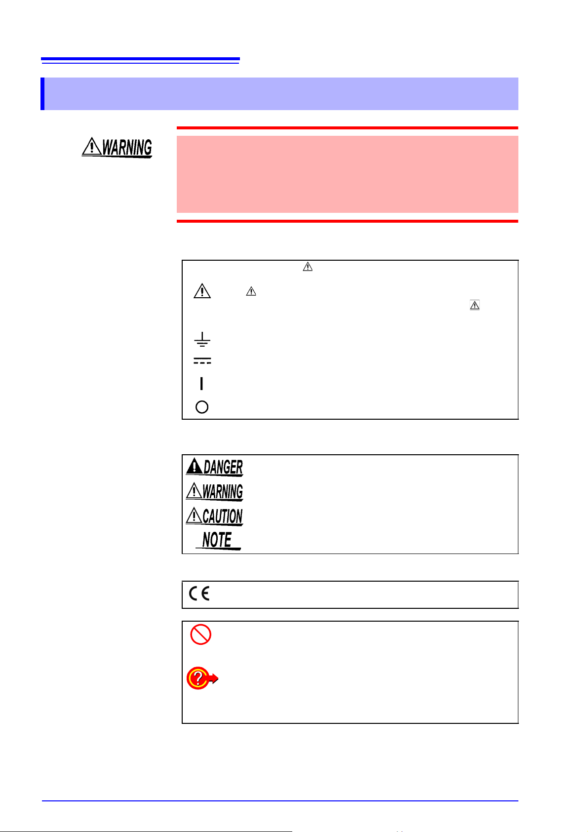
In the manual, the symbol indicates particularly important information
that the user should read before using the instrument.
The symbol printed on the instrument indicates that the user should
refer to a corresponding topic in the manual (marked with the symbol)
before using the relevant function.
The following symbols in this manual indicate the relative importance of cautions
and warnings.
Symbols for Various Standards
Other Symbols
Indicates a grounding terminal.
Indicates DC (Direct Current).
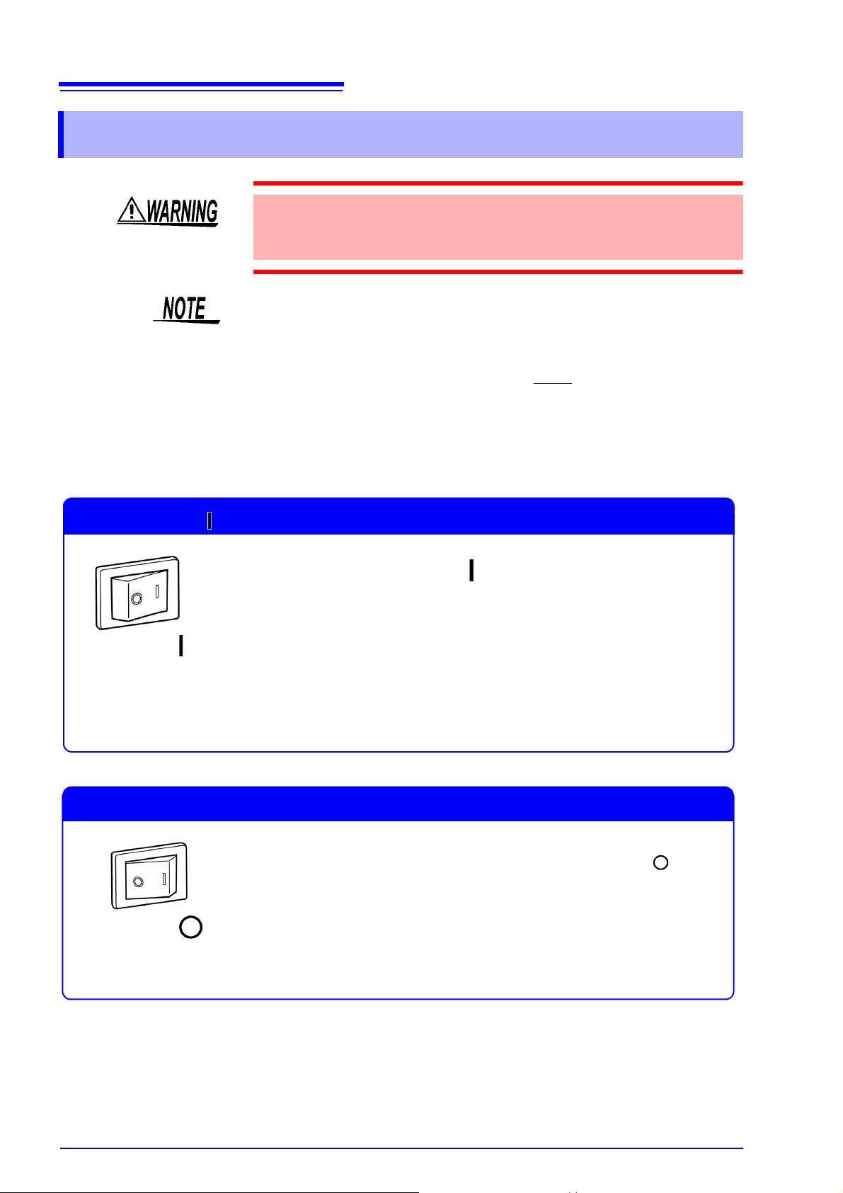
Indicates the ON side of the power switch.
Indicates the OFF side of the power switch.
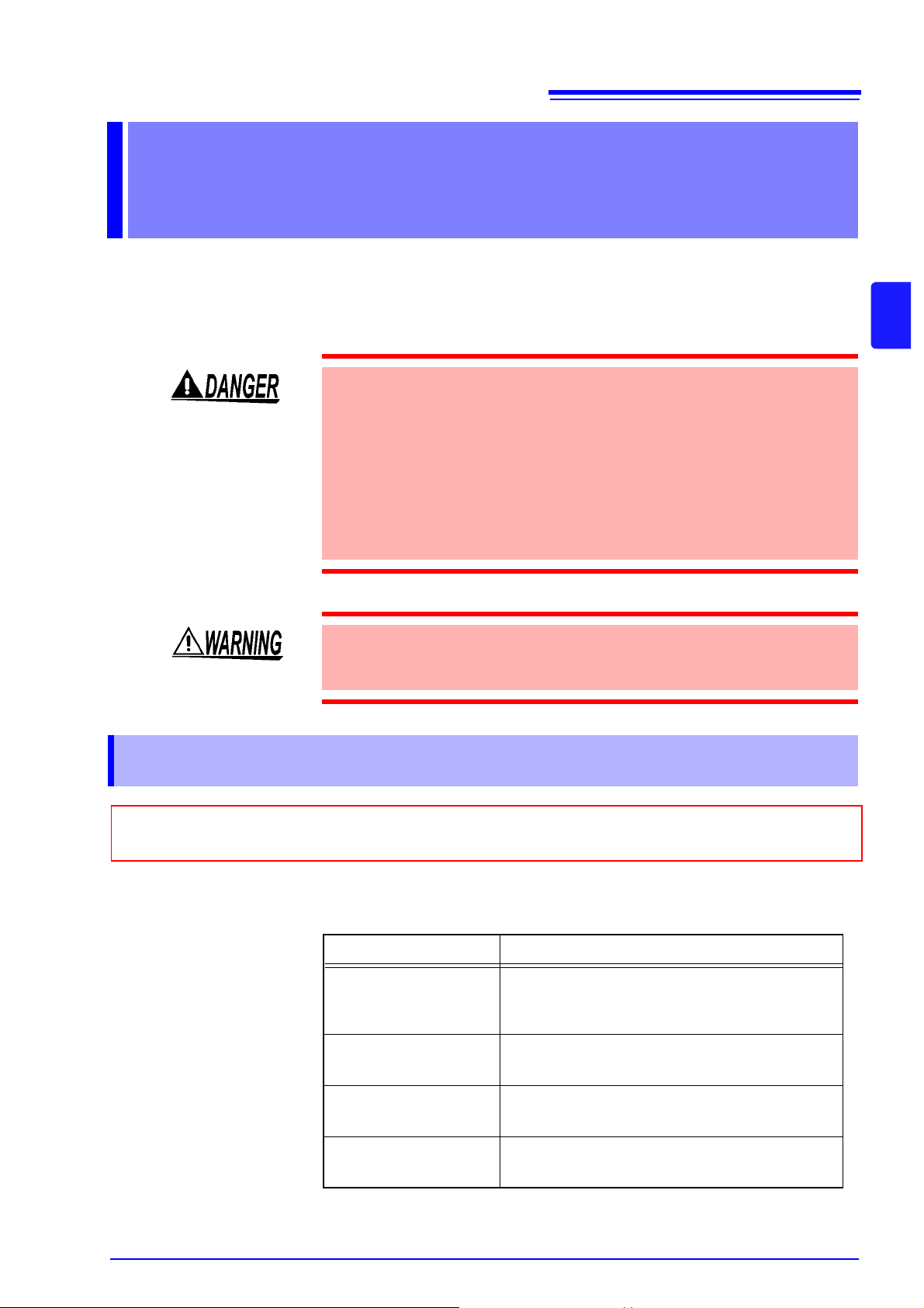
Indicates that incorrect operation presents an extreme hazard that
could result in serious injury or death to the user.
Indicates that incorrect oper ation prese nts a significant hazard that
could result in serious injury or death to the user.
Indicates that incorrect operation presents a possibility of injury to
the user or damage to the instrument.
Indicates advisory items related to performance or correct operation of the instrument.
This symbol indicates that the product conforms to safety regulations set
out by the EC Directive.
Indicates a prohibited action.
(.p)
*
Indicates the location of reference information.
Indicates quick references for operation and remedies for troubleshooting.
Indicates that descriptive information is provided below.
Page 9
3
Safety Information
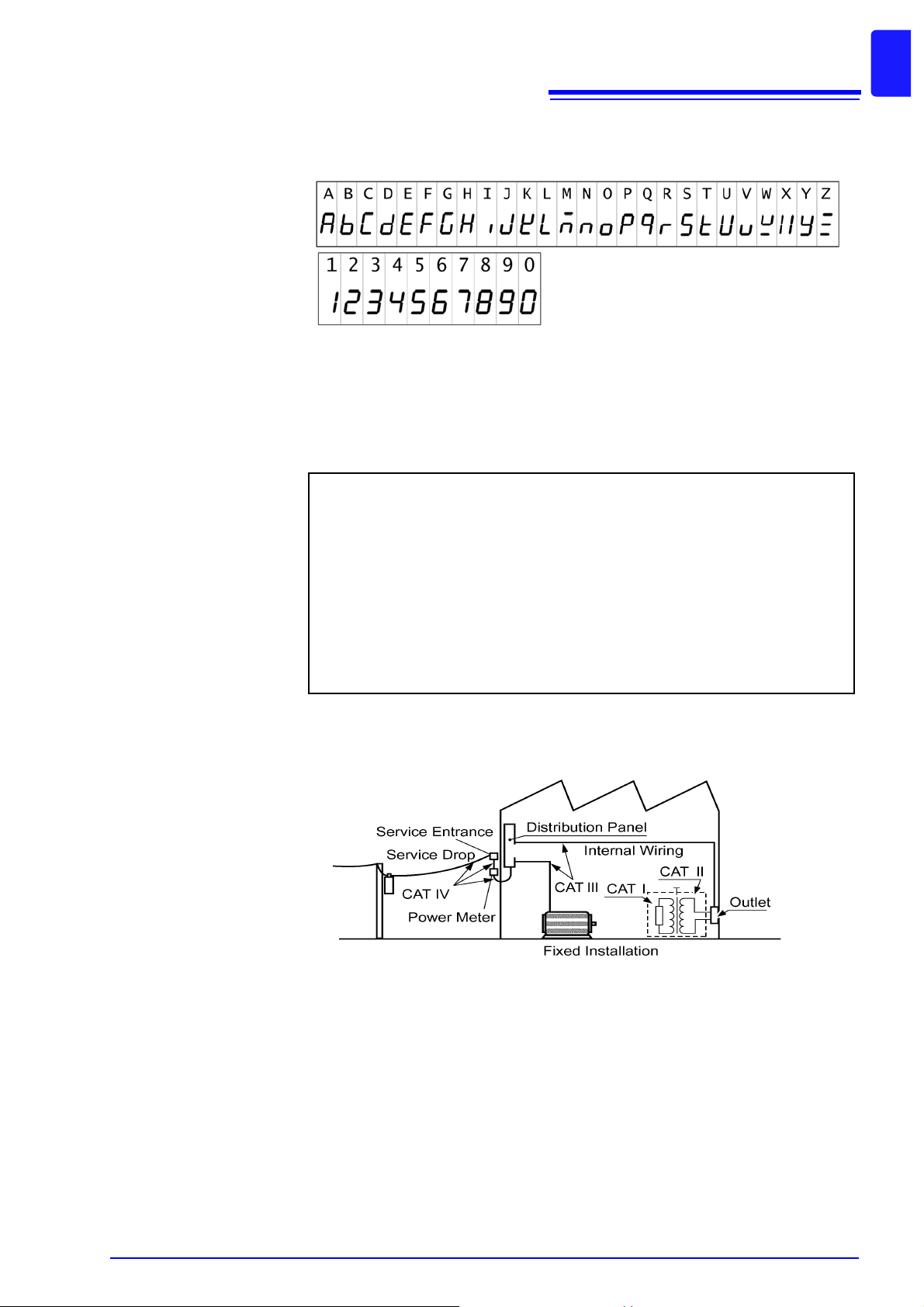
Screen display
The screen of this instrument displays characters in the following manner.
Measurement categories (Overvoltage categories)
This instrument complies with CAT I safety requirements.
To ensure safe operati on of measurement instruments, IEC 6 1010 establishes
safety standards for various electrical environments, categorized as CAT I to
CAT IV, and called measurement categories.
CAT I
CAT II
Secondary electrical circ uits connec ted to an AC ele ctrical o utlet throug h a
transformer or similar device.
Primary electrical circ uits in equi pment conne cted to an AC el ectrical outl et
by a power cord (portable tools, household appliances, etc.)
CAT II covers directly measuring electrical outlet receptacles.
Accuracy
CAT III
CAT IV
Using a measurement instrument in an environment designated wit h a highernumbered category th an that for which the in strument is rated c ould result in a
severe accident, and must be carefully avoided.
We define measurement tolerances in terms of f.s. (full scale), rdg. (reading) and
dgt. (digit) values, with the following meanings:
Primary electrical circuits of heavy equipment (fixed installations) connected directly to the distri but ion pa nel, an d feede rs from the dis tributi on pan el
to outlets.
The circuit from th e servi ce drop to the serv ice e ntranc e, and to t he po wer
meter and primary overcurrent protection device (distribution panel).
(maximum display value)
f.s.
The maximum displayable value. This is usually the name of the currently
selected range.
(reading or displayed value)
rdg.
The value currently being measured and indicated on the measuring instrument.
(resolution)
dgt.
The smallest displayable unit on a digital measuring instrument, i.e., the
input value that causes the digital display to show a "1" as the least-significant digit.
Page 10
4
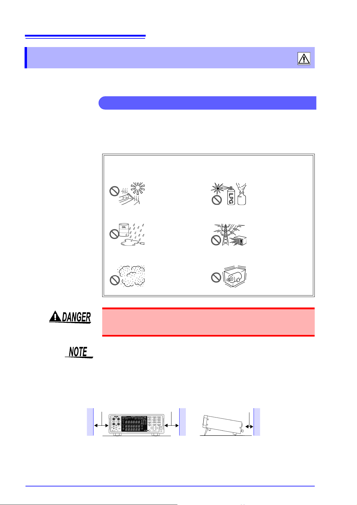
Instrument Install ation and Operating Environment
The instrument can be used with the stand. ( p.12)
It can also be rack-mounted. Appendix (
p.A16)
50 mm or more
10 mm or more
Rear
50 mm or more
Safety Information
Operating Precautions
Follow these precauti ons to ensure s afe opera tion and to obtai n the ful l bene fits
of the various functions.
Operating temperature and humidity:
0 to 40°C (32 ± 104°F), 80%RH or less (non-condensating)
Temperature and humidity range for guaranteed accuracy:
23 ± 5°C (73 ± 9°F), 80% RH or less (non-condensating)
Avoid the following locati ons that could cause an acc ident or damage to the
instrument.
Exposed to direct sunlight
Exposed to high temperature
In the presence of corrosive or explosiv e gases
To av oid electr ic shock, do n ot remov e the instrum ent's cas e. The inter nal components of the instrume nt carry high voltages a nd may become ve ry hot during
operation.
Avoid using near electrically noisy devices, as the noise may impinge upon the
test object and cause unreliable measurements.
Installation Precautions
• The instrument should be operated only with the bottom downwards.
• Do not place the instrument on an unstable or slanted surface.
Exposed to water, oil,
other chemicals, or
solvents
Exposed to high humidity or condensation
Exposed to high levels of particulate dust
Exposed to strong electromagnetic fields
Near electromagnetic
radiators
Subject to vibration
Page 11
5
Preliminary Checks
Measurement Precautions
Safety Information
Before using the instrument the first time, verify that it operates normally to
ensure that the no damage oc curred during stor age or shipping. If you fi nd any
damage, contact your dealer or Hioki representative.
Before using the instrument, make sure that the insulation on the power cord
and test leads is undamaged and that no bare conductors are improperly
exposed. Using the instrument in such conditions could cause an electric
shock, so contact your dealer or Hioki representative for replacements.
• To a void electri cal shock, be ca reful to avoid shorting l ive lines wit h the test
leads.
• To avoid inju ry or damage to the instr ument, do n ot attempt to measure AC
voltage and AC current, or DC voltage exceed ing
(BT3563).
• The maximum rated voltage betwee n input terminals and ground is
DC. Attempting to measure voltages exceeding 70 V (BT3562), 300 V
(BT3563) with respect to ground cou ld damage the instrum ent and result in
personal injury.
• Never connect a bat tery cell or module to a motor or other load while it is
being measured. Doing so may result in a surge voltage, which may damage
the instrument or cause injury.
± 60 V (BT3562), 300 V
± 70 V
• To prevent electrical shock, verify the ratings of the measurement leads
before measurement and exercise care not to measure voltages that exceed
those ratings.
• Do not touch the metallic tip of probes after measuring high-voltage batte ries. Doing so may resu lt in electr ical shock si nce inte rnal ins trume nt components could retain a charge unde r thos e c ond iti on s. (Int er nal di schar ge tim e:
Approx. 20 sec.)
• To av oi d sho rt-c irc ui t ac ciden ts, co nne ct the probe's banana term ina ls to t he
instrument before connecting the probes to the battery.
Page 12

6
Before Connecting and Powering On
Handling the Instru m en t
Handling the Test Leads and Cables
Safety Information
• Use only the specified test leads and cables. Using a non-specified cable may
result in incorrect measurements due to poor connection or other reasons.
• To ens ure cert ified mea suremen t accurac y, allow at least 30 minutes warmup. After warm-up, be sure to execute self-calibration.
See "4.10 Self-Calibration" ( p.69).
• The input circuit ry includes a protecti ve fuse. Measuremen t is not possible
when the fuse is blown.
• This instrument internally stores (backs up) all settings (except memory function and measurement values), such as measurement range, comparator
settings and etc., but only when no operation is performed for a certain time.
Therefore, to preserve settings, do not turn the power off for a short time
(about five seconds) after changing a setting. However, measurement settings made through the RS-232C or GP-IB interface and measurement settings loaded by LOAD
• Select an appropriate measurement range when measuring batteries. Using
a low range such as 3 mΩ to measure a button cell or other battery that has
high internal resistance may result in an open-terminal voltage (approx. 4
V), causing the battery to be charged.
signals of the EXT I/O connector are not memorized.
• Before turning the instrument on, make sure the supply voltage matches that
indicated on the i ts powe r con nec to r. Connection to an im pr op er su ppl y vo ltage may damage the instrument and present an electrical hazard.
• To avoid electrical accidents an d to maintain th e safety spec ifications of this
instrument, connect the power cord only to a 3-contact (two-conductor +
ground) outlet.
To suppress noise, the in strument needs to be set to matc h the frequency of
the power source. Before operating, set the instrument to the frequency of your
commercial power . If the supp ly freque ncy is not set prope rly, measur ements
will be unstable.
See "2.5 Selecting the Line Frequency" ( p.20).
Make sure the power is turned off before connecting or disconnecting the
power cord.
• To avoid damage to the instrument, protect it from physical shock when
transporting and handling. Be especially careful to avoid physical shock from
dropping.
• Do not apply heavy d ownward pres sure wit h the stand exte nded. The stand
could be damaged.
• T o avoid breaking the test leads and cables, do not bend or pull them.
• Avoid stepping on o r pin ching ca ble s, whi ch co uld dam age the cable insul a-
tion.
Page 13

7
1.1 Product Overview
1
Overview Chapter 1
1.1 Product Overview
The Model BT3562, BT3563 Battery Hitester measure battery internal resistance
using a four-terminal, 1-kHz AC method, while simultaneously measuring DC
voltage (electromoti ve force [emf]). The high-precision, fas t measurement performance and extensive interface capabilities make these models ideal for incorporating into battery testing production lines.
Chapter 1 Overview
Page 14

8
1.2 Features
1.2 Features
Simultaneously Measures Battery Internal Resistance and Voltage
The four-terminal AC method measures resistance and DC voltage simultaneously, so battery internal resistance and emf are measured and judged at
once.
High-Precision Measurements
The instrument provide s high-resolution resistance (0.1 μ
surements (10 μV). High precision (
measurements.
± 0.01% rdg.) ensures accurate voltage
Ω) and voltage mea-
High-Speed Meas urements
Simultaneous resis tance and voltage measur ements can be performed as fast
as once every 20 ms.
(Response time of approx. 10 ms + sampling time of approx. 8 ms)
High-voltage measurement
The Model BT3563 supports measurement of high-voltage batteries of up to 300
V (the Model BT3562 supports measurement of up to 60 V).
Comparator Functions
Resistance and volt age measur ement va lues ar e judged in three ca tegor ies (Hi,
IN and Lo), with results clearly di splayed. A compara tor judgment beeper a lso
provides distinc t sounds to indicate pass/fail judgm ents and to faci litate correct
recognition of judgment results.
Statistical Calc ulation Functions
Maximum, minimum and av erag e measurement values, standard dev ia tio n, pr ocess capability indices and other values can be automatically calculated for
applications such as production management. Calculation results can also be
applied as comparator setting values.
Measurement Value Memory Function
The instrument incl udes a Memory function and storage capacity for up to 400
pairs of measurement val ues. When making many sequential me asurements at
high speed and sendin g the me asur ed values to a PC a fter each measu remen t,
the time to switch te st objects can become unsatisfacto rily long. The Memory
function can avoid th e slow-down by sending stor ed measurements in batches
during idle times.
EXT I/O Interface
EXT I/O and RS-232C inter faces are equip ped as standard, supp orting transfer
rates up to 38,400 bps. Model BT3562-01 and BT3563 -01 also supports GP -IB
and analog output.
Printing Measurement Values and Statistical Results
Connect the optional Model 9670 Pr inter (option) to print measurement values
and statistical calculation results.
Page 15

9
Front Panel
POWER Switch
Turns the instrument on and off (Standby).
Turns the power on and off (standby).
Off (standby) R On (cancel standby)
On (press and hold for 1 second) R Off (standby)
(The main power switch is located on the back of the
instrument.)
Input Terminals (INPUT)
Connect the optional test leads.
See
"2.3 Connecting the Optional T est Leads" ( p.17).
Operating Keys
( p.11)
Sub Display
( p.10)
SOURCE-H
SOURCE-L
SENSE-H
SENSE-L
Main Display
( p.10)
See
"2.4 T u rn ing the P ow e r O n an d Off" ( p.18)
1.3 Names and Functions of Parts
1.3 Names and Functions of Parts
1
Chapter 1 Overview
Page 16
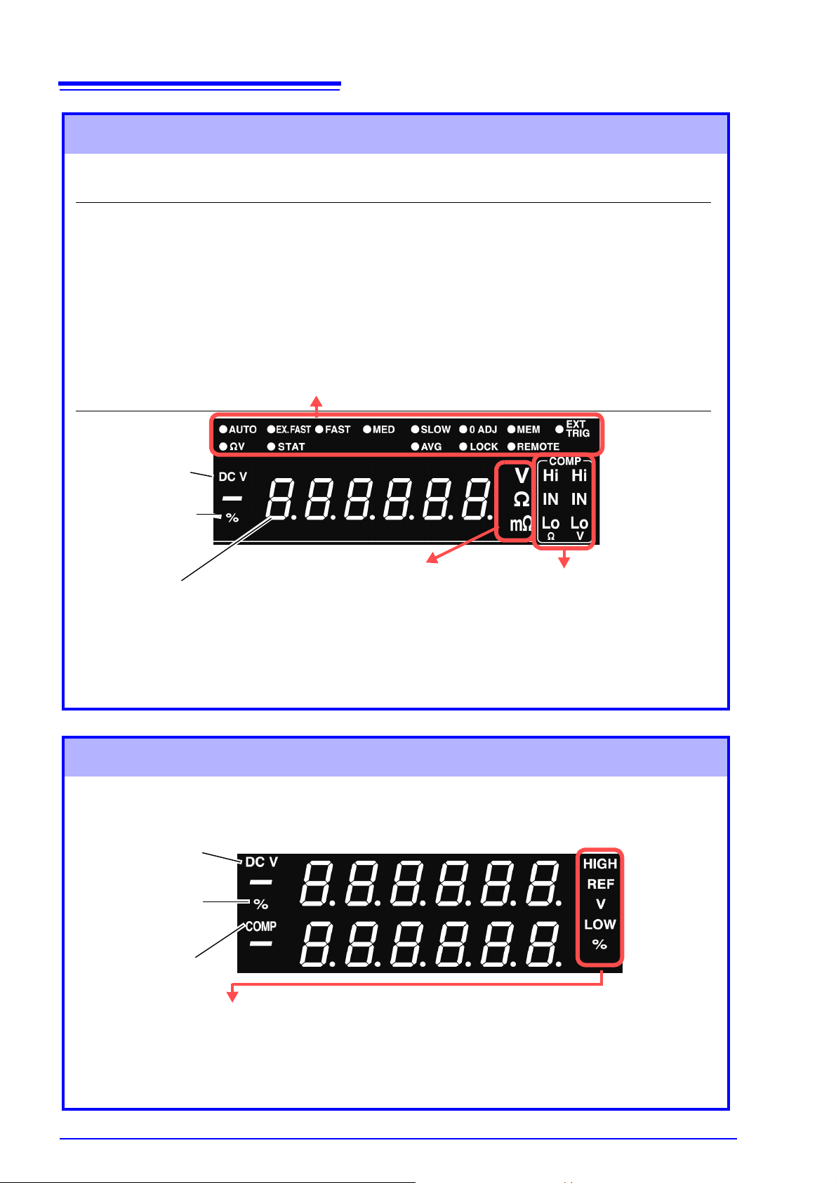
10
Lit when measuring
voltage.
Indicates percentage
units during relative
value com parator operation.
Shows measured
value or setting item.
Main Display
(Upper row)
AUTO
Lit when measuring with Auto-Ranging.
EX.FAST, FAST, MED, SLOW
The selected Sampling Rate is lit.
0 ADJ
Lit when measuring in a range for
which Zero-Adjustment has been performed.
MEM
Lit when the Memory function is enabled.
EXT TRIG
Lit when the External Trigger function
is enabled.
(Lower row)
ΩV
Lit when the ΩV (Resistance and
Voltage measurement) mode is selected.
STAT
Lit when the Statistical Calcula tion
function is enabled.
AVG
Lit when measuring with the Averaging setting enabled.
LOCK
Lit when the keys are locked.
REMOTE
Lit during communications.
The current measu rement mode is indicated wh ile measuring, and the setti ng item is displayed while
making settings .
Shows Comparator Decision Result.
Hi
Indicates that the measured value is
above the upper threshold.
IN
Indicates that the m e as ure d value is between the upper an d l ower thresholds.
Lo
Indicates that the m eas ure d v al ue is below the lower threshold.
Units of displayed measuremen t
V
Unit of voltage
Ω
Unit of resistance (lit w hen the 3
Ω to 3000 Ω range is selected)
mΩ
Unit of resistance (lit w hen the 3
mΩ το 300 mΩ range is selected)
Indicates Voltage measurement mode
Indicates percentage
units during relative value
comparator operation
While measuring, indicates the Comparator
function is enabled.
HIGH, LOW Indicates that absolute value comparator operation is enabled
(while measuring), and also when setting.
REF, % Indicates that relative value comparator operation is enabled
(while measuring), and also when setting.
V Indicates voltage measurement units.
Upper and lower thresholds and other settings are displayed (when set).
Sub Display
1.3 Names and Functions of Parts
Page 17
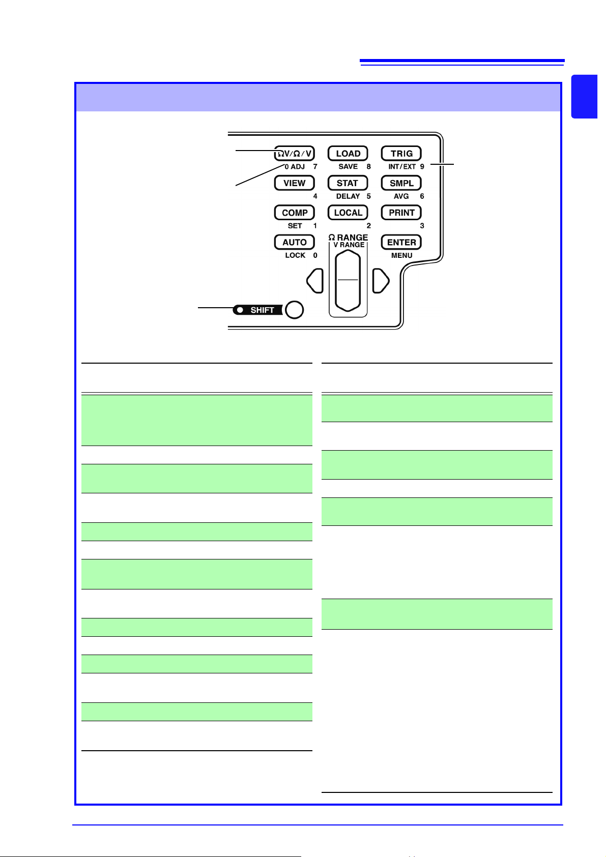
Operating Keys
To use a function marked on a
key, just press the key.
To use a function printed under a key (blue letter), press
the SHIFT key first (and confirm the SHIFT lamp is lit),
and then the key.
SHIFT Lamp
Use as ten-keys to
enter numer ic al values.
(Numerical values
can be used with
the RANGE key.)
[ ]: Enabled after pressing the SHIFT key (SHIFT lamp lit ).
Operating
Key
Description
ΩV/ Ω/ V
Selects Measurement mode.
(Resistance and voltage measurement, Resistance measur ement or
Voltage measurement)
[0 ADJ]
Executes Zero-Adjustment.
LOAD
Loads a saved measurement configuration (Panel settings).
[SAVE]
Saves the current measurement configuration (Panel settings).
TRIG
Executes a Manual Trigger event.
[INT/EXT ]
Selects internal/external triggering.
VIEW
Switches the view mode of the ΩV
mode.
STAT
Displays and sets Statistical Calculation results.
[DELAY]
Sets the Trigger Delay.
SMPL
Selects the Sampling Rate.
[AVG]
Activates Averaging function settings.
COMP
Switches the Comparator function on
and off.
[SET]
Activates Comparator function setting.
LOCAL
Cancels remote control (RMT) and reenables key operations.
Operating
Key
Description
PRINT
Sends measurement values and statistical calculation results to the printer.
AUTO
Switches between Auto and Manual
range selection.
[LOCK]
Switches the Key-Lock function on and
off.
ENTER
Applies settings.
[MENU]
Selects various operating functions
and settings.
Ω RANGE
Up/Down:
Changes setting value or numerical
value, and sets the resistance measurement range.
Left/Right:
Moves the setting item or digit.
[V
RANGE]
Up/Down:
Sets voltage measurement range.
SHIFT
• Enables the functions of the operating keys marked in blue.
The lamp is lit when the SHIFT
state is active.
• Cancels settings in various setting
displays. (Returns to the Measurement display without applying settings.) However, this does not apply
to Menu display. However, from a
menu item display, changed settings are not canceled, but
accepted as the display returns to
measurement display (except after
Zero-Adjustment clear or resetting).
11
1.3 Names and Functions of Parts
1
Chapter 1 Overview
Page 18
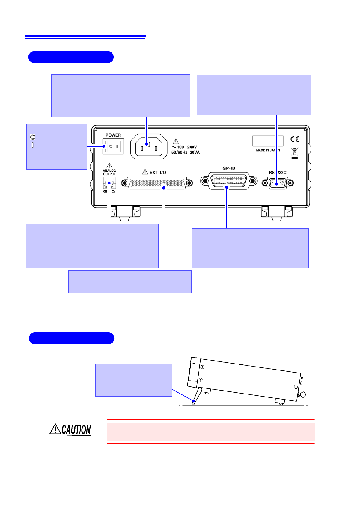
12
EXT I/O Connector
Connect here to use the EXT I/O interface.
GP-IB Connector (Model BT3562-01,
BT3563-01 only)
Connect here to use the GP-IB interface.
See " Attaching the Connector" ( p.99).
Power Inlet
Connect the supplied power cord here.
See "2.2 Connecting the Power Cord" ( p.16).
RS-232C Connector
Connection for the printer or RS-232C
interface.
See
" Attaching the C onne ctor" ( p.99).
* The illustration shows the Model BT3563-01 Battery Hitester (GP-IB version).
See "Chapter 5 External Control (EXT I/O)" ( p.75 )
Rear Panel
Analog output connector
(Model BT3562-01, BT3563-01 only).
Connect when using analog output (of resistance measured values).
See "Chapter 8 RS-232C/GP-IB Inter fac es"
( p.97)
Main power switch
: Main power off
:Main power on
See "2.4 Turning the
Power On and Off"
( p.18)
Side View
Stand
Can be opened to tilt the
front panel upwards.
1.3 Names and Functions of Parts
Do not apply heavy downward pressure with the stand e xtended. The stand
could be damaged.
Page 19
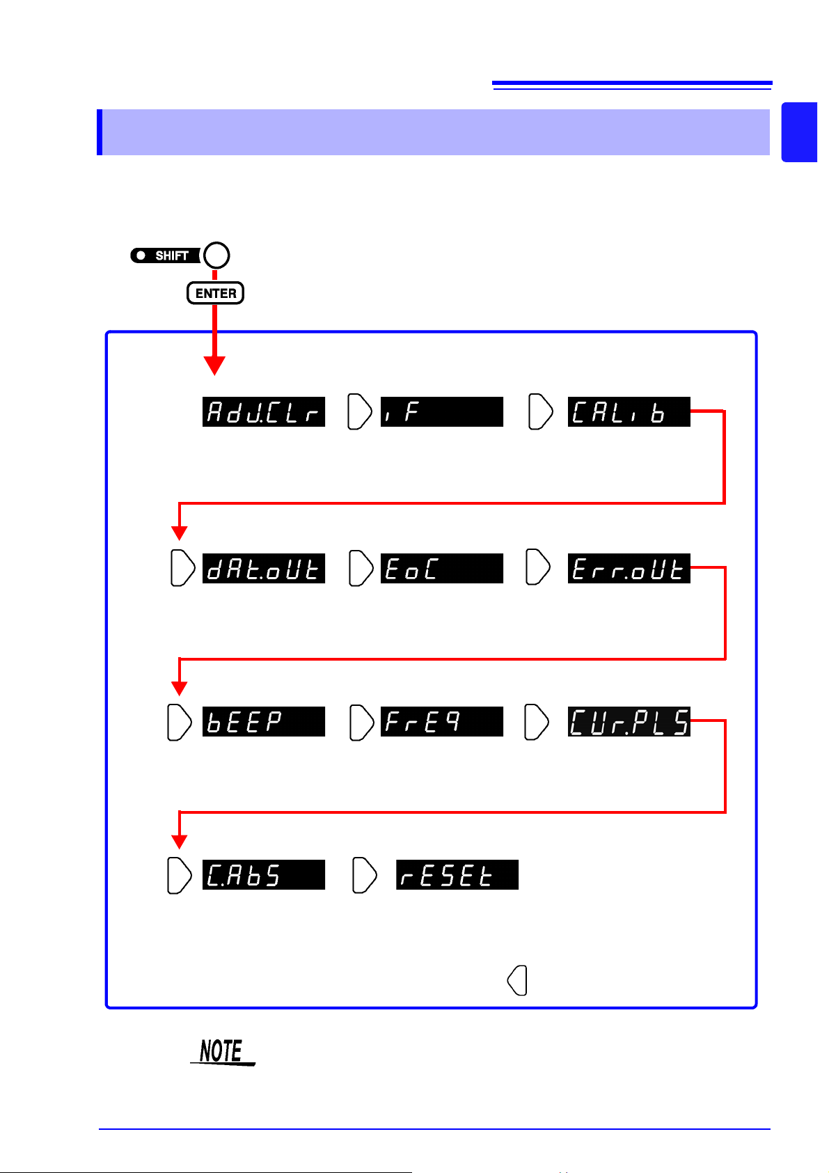
13
ERR Output Selection
display (
p.80)
Zero-Adjustment Clear
display (
p.31)
Interface Selection
display (
p.101)
Self-Calibration setting
display (
p.69)
Measurement Value Output
function setting display
( p.70)
Key Beeper setting
display (
p.71)
Line Frequency set-
ting display
(
p.20)
Measurement Current
Pulse Output
display(
p.57)
(SHIFT Lamp lit)
The Menu display appears.
(Main Display)
The up/down RANGE key change s the setting
shown on the Sub Display.
Pressing this key returns to the
previous item display.
EOM-signal setup dis-
play (
p.80)
Configuring the Absolute
Value Judgment display
( p.51)
Reset display
(
p.72)
1.4 Menu Display Sequence (SHIFT → ENTER)
1.4 Menu Display Sequence (SHIFT → ENTER)
Various auxiliary settings can be performed from the menu item displays.
1
Chapter 1 Overview
Settings on the menu item displays are applied and saved internally when
changed.
Page 20
14
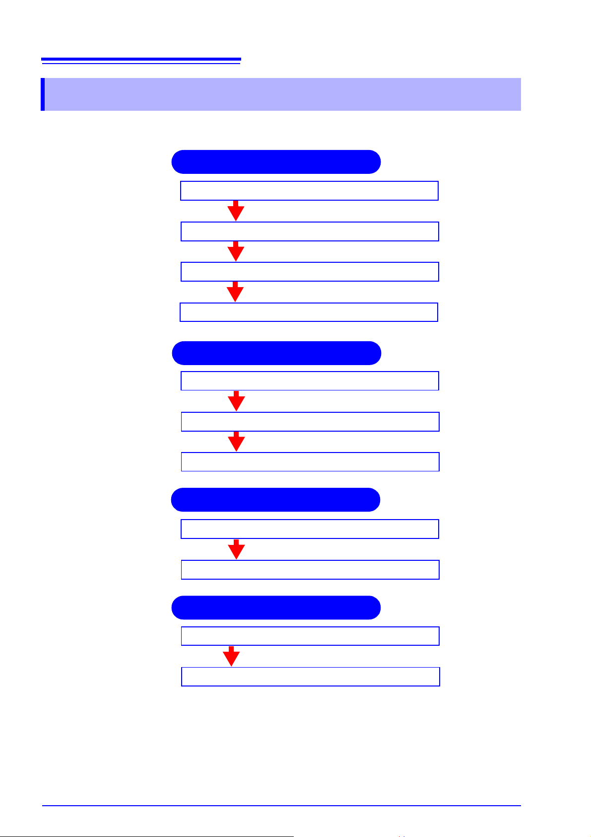
Selecting the line frequency ( p.20)
Turning the power on ( p.18)
Connecting the test leads ( p.17)
Connecting the power cord ( p.16)
Selecting sampling rate ( p.30)
Selecting measurement range ( p.27)
Selecting measurement mode ( p.26)
Executing zero-adjustment
Short the test leads together ( p.31)
Measurement Preparations
Instrument’s Settings
Zero-Adjustment
Read the measured value ( p.34)
Connect the test leads to a test object.
Measurement Start
1.5 Measurement Flowchart
1.5 Measurement Flowchart
The basic measurement process flow is as follows:
For details about the fun ction s that can be appl ied to m easurem ent val ues suc h
as comparator, trigger and averaging functions, refer to "Chapter 4 Applied
Measurement" ( p.37).
Page 21
2.1 Preparation Flowchart
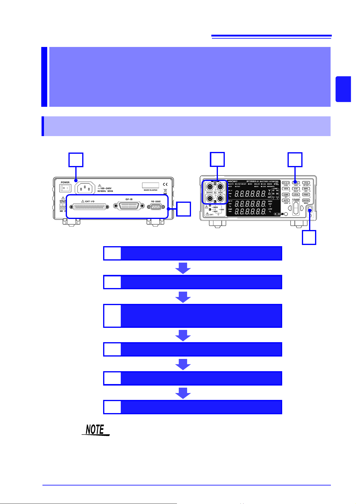
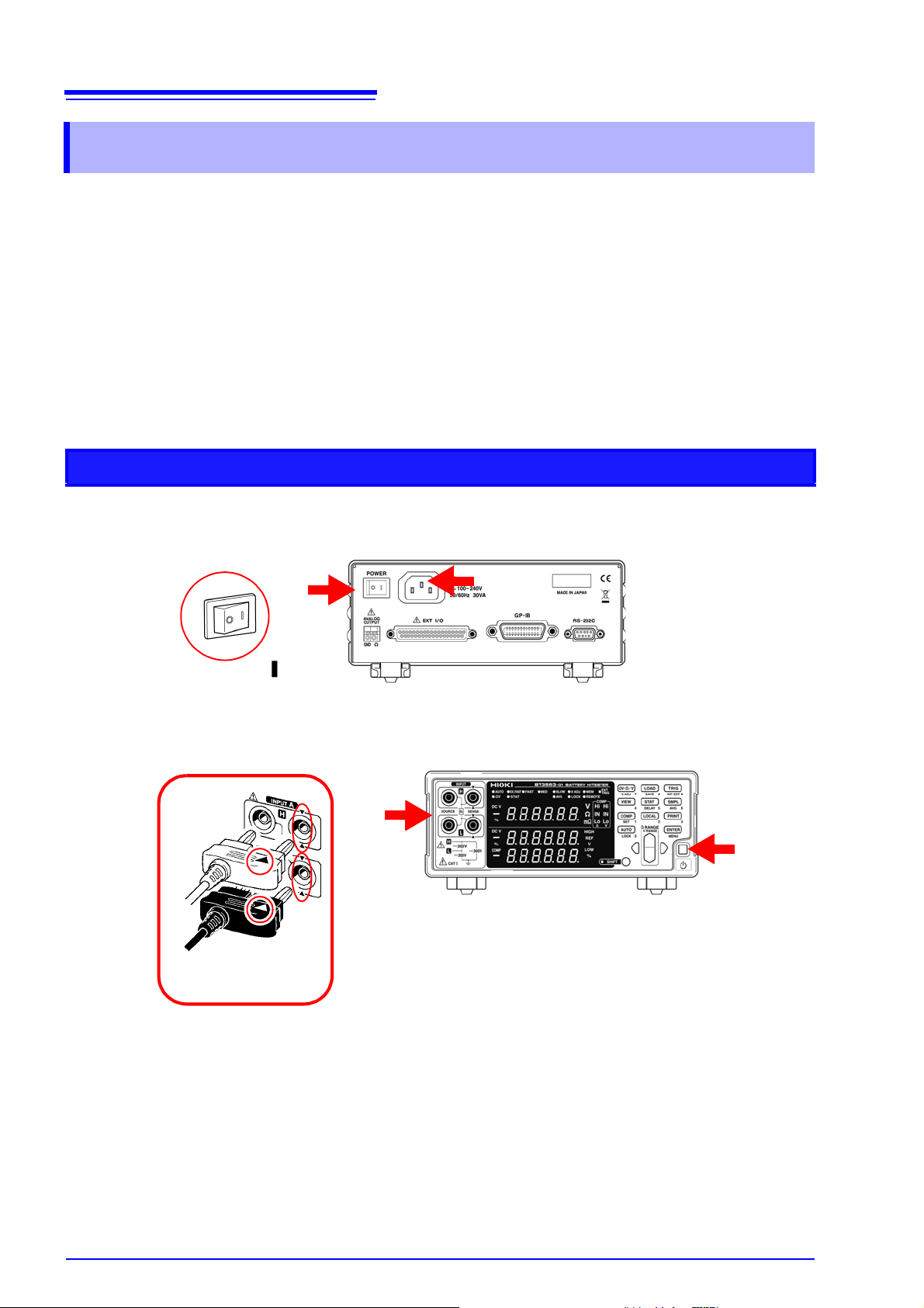
Rear Panel
2
1
4
( p.17)( p.16)
( p.18)
3
5
Front Panel
Measurement
Preparations Chapter 2
2.1 Pre paration Flowchart
This procedure de scr ib es inst ru me nt pr e par at ions such as making connect io n s and tu r ni ng po we r on.
15
2
Chapter 2 Measurement Preparations
1
2
3
4
5
6
Connecting the power cord.
Connect the test leads to the instrument.
Connect the EXT I/O connector and interface connector.
Turn the power on.
Set measurement settings.
Start measurement.
Verify that the instrument’ s line frequency is correctly set w hen using it for the
first time and after initialization following repair or recalibration.
See "2.5 Selecting the Line Frequency" ( p.20).
( p.16)
( p.17)
( p.99)
( p.18)
( p.21)
Page 22
16
12
Rear Panel
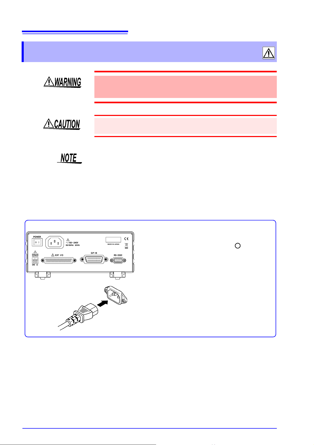
1. Confirm that the instrument's Main power
switch (rear panel) is OFF(
).
2. Check that the power supply voltage ( 100
V to 240 V) is correct, and connect the
power cord to the power inlet socket on
the rear of the instrument.
3. Plug the power cord into the AC outlet.
2.2 Connecting the Power Cord
2.2 Connecting the Power Cord
To a void electrical accidents and t o maintain the safety speci fications of this
instrument, connect the power cord only to a 3-contact (two-conductor +
ground) outlet.
To avoid damaging the power cord, grasp the plug, not the cord, when unplugging it from the power outlet.
To suppress noise, the instrument needs to be set to match the line frequency.
Before operating, set the instrument to the frequency of your commercial
power. If the supply frequency is not set properly, measurements will be unstable.
See "2.5 Selecting the Line Frequency" ( p.20).
Make sure the power is turned off before connecting or disconnecting the
power cord.
Page 23
2.3 Connecting the Optional Test Leads
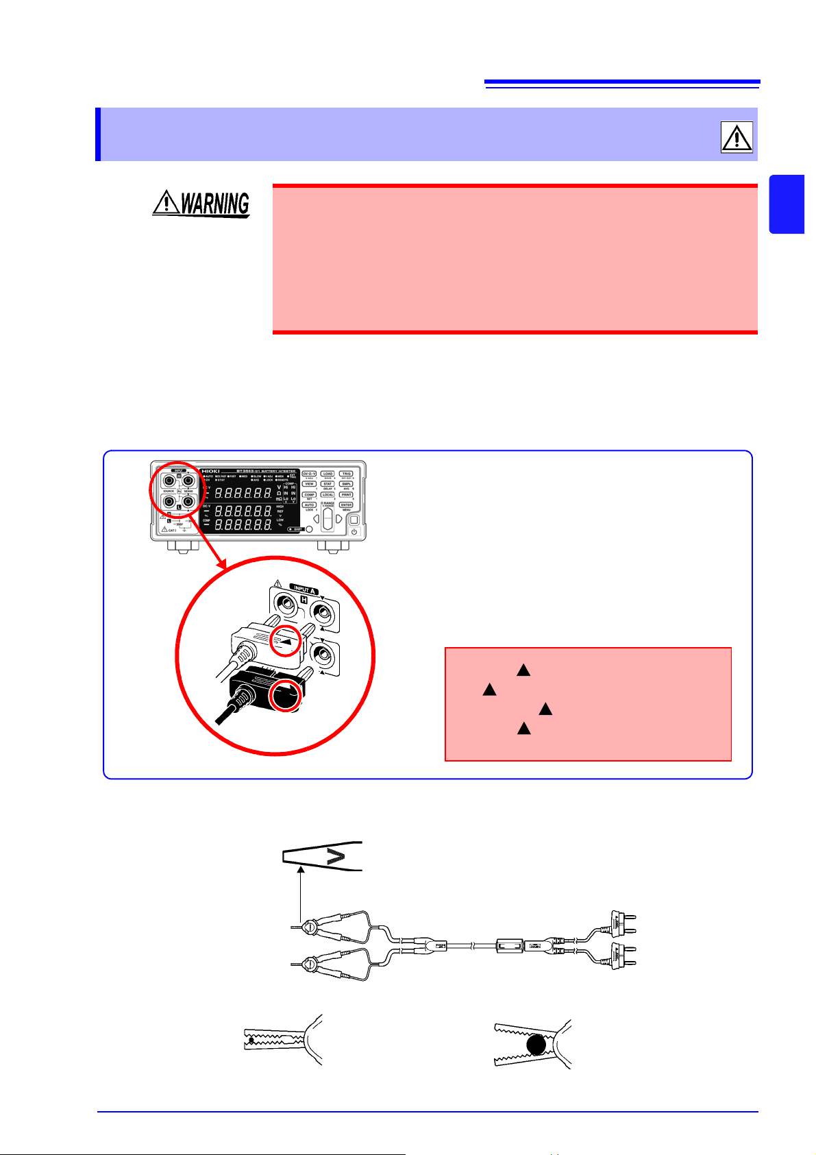
Plug the mark on the red lead into the
red marked jack on the instrument,
and plug the mark on the black lead int o
the black marked jack on the instrument.
Example: Optional model 9287-10 CLIP TYPE LEAD
Black Lead
Red Lead
1. Confirm that the instrument's Power
switch is OFF.
2. Verify that nothing is connected to the tips
of the four-terminal measurement leads.
3. Connect four-terminal test leads such as
the 9287-10 CLIP TYPE LEAD to INPUT
A.
SOURCE
SENSE
SENSE
SENSE
SOURCE
SOURCE
SOURCE
SENSE
Red
Black
Red
Black
The side with “V” mark is SENSE.
When clippi ng a t hi n li ne
(Clip the line at the tip,
serrated part of the
jaws.)
When clipping a thick line
(Clip the line at the
deep, non-serrated part
of the jaws.)
2.3 Connecting the Optional Test Leads
• To prevent an accident caused by short-ci rcuiting the bat tery, be sure to verify
that nothing is connected to the tips of the measurement leads before connecting the leads to or discon necting them from the instrument. ( Contact between
the banana terminals while the tips of the measurement leads are connected
to the battery will short-circuit the battery, possibly resulting in serious injury.)
• To prevent electrical shock, verify the ratings of the measurement leads before
measurement and ex ercise care not to measure voltages that exceed those
ratings.
Test leads are not included as standard accessor ies with the instrument, so the
appropriate options need to be purchased separately or constructed according to
the user’s application requirements. To constr uct custom test leads, ref er to "Pre-
cautions for Making Custom Test Leads"(
terminals on this instrument consist of four separate banana jacks.
See "Appendix 1 Precautions for Making Custom Test Leads"( p.A1).
p.A1). The resistance measurement
17
2
Chapter 2 Measurement Preparations
About Test Leads ______________________________________________
(Example: Model 9287-10 CLIP TYPE LEAD)
Page 24
18
Turn on the main power switch on ( ) the rear of the instrument.
The instrument will st art up i n the standby state in which it was last
turned off. (The instrument ships in the standby state.)
Turning On ( ) the Main Power Switc h (Rear of In strument)
Power ON
Turn off the main power switch on the rear of the instrument.( ).
Turning the Power Off
Power OFF
2.4 Turning the Power On and Off
2.4 Turning the Power On and Off
Before turning the ins trument on, make su re the supply voltage m atches that
indicated on the its power co nnector. Connection to an improper supply voltage may damage the instrument and pres ent an electr ical haza rd .
• The measurement setting state is the same as when the power was previously turned off (backup).
To preserve changes to settings, wait a short time (about five seconds) after
changing a setting before turning power off.
• However, measurement settings made through the RS-232C or GP-IB interface and meas ur eme nt s etti ngs l oad ed by LO AD
nector are not memorized.
• Before starting to measure, allow 30 minutes for warm-up.
After warm-up, be sure to perform a self-calibration.
See "4.10 Self-Calibration" ( p.69).
signals of the EXT I/O con-
Page 25
19
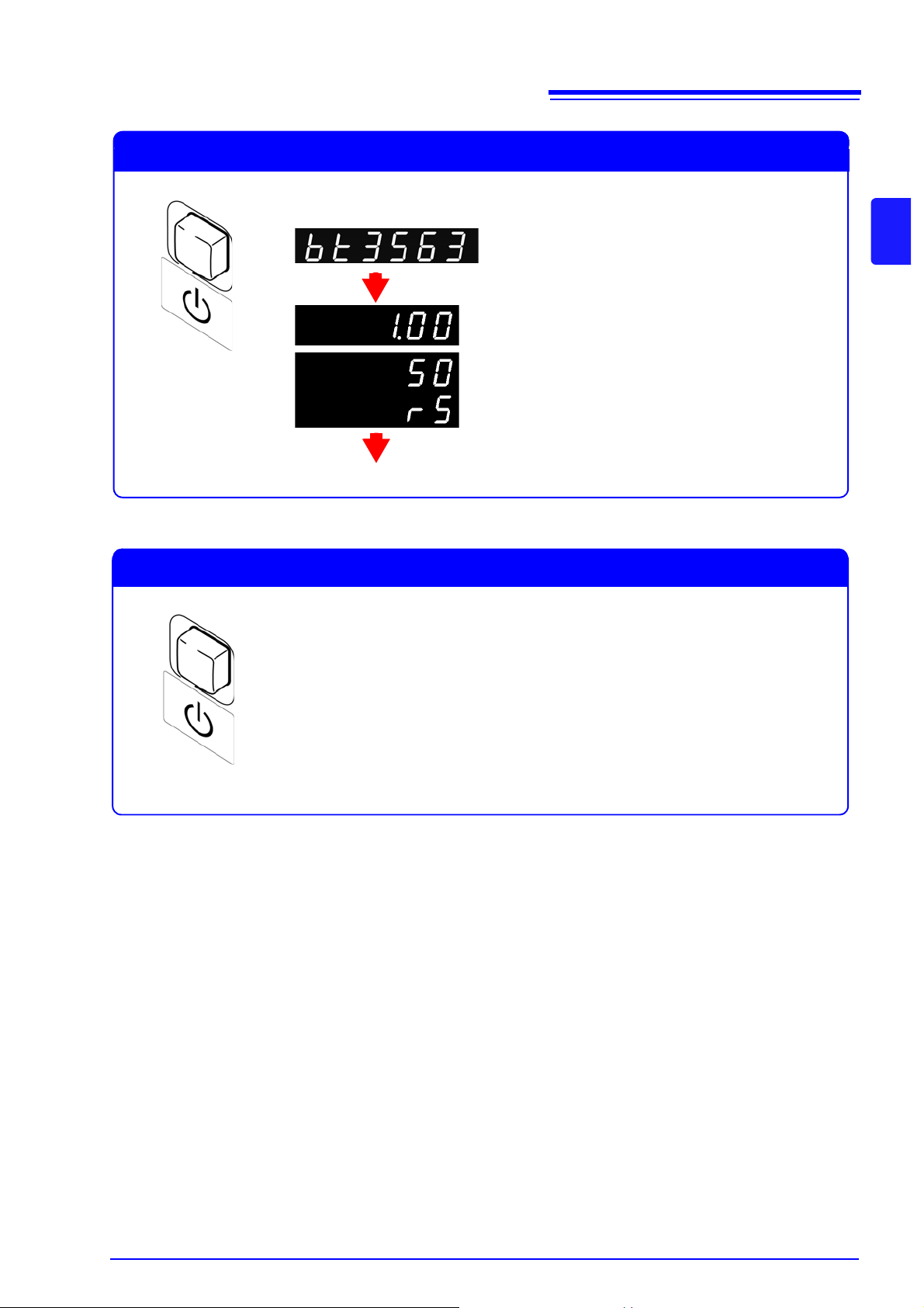
Press the power switch on the front of the instrument while it is in the
standby state.
Cancelling the Standby State
(Main Display)
Software version
(Sub Display)
Line frequency
Interface
(Main Display)
Model name
The measurement display appears.
Press and hold the power switch on the front of the instrument for
approximately 1 second while it is in the operating state.
Placing the Instrument in the Standby State
2.4 Turning the Power On and Off
2
Chapter 2 Measurement Preparations
Page 26
20
(Main Display)
(Sub Display)
(Main Display)
(Sub Display)
(Main Display)
(Sub Display) flashing
2.5 Selecting the Line Frequency
2.5 Selecting the Line Frequency
The instrument's power supply frequency must be set in order to eliminate noise.
Although the power sup ply frequency setting is co nfigured automatica lly ("AUTO") by defaul t, it can also be
set manually. Measured values will not stabilize if the power supply frequency is not set properly.
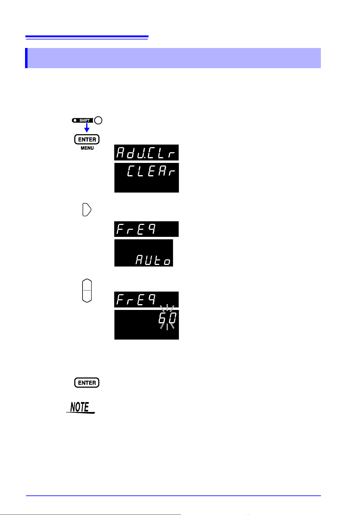
1
2
3
(The SHIFT indicator lights up.)
The Menu display appears.
Select the Line Frequency setting display.
See "1.4 Menu Display Sequence (SHIFT → ENTE R ) " ( p.13 ).
Select the frequency of the AC mains supply being used.
4
AUTO.... Automatic configuration of power supply frequency
50..........50 Hz
60..........60 Hz
Applies settings and returns to the Measurement displ ay.
• When set to aut omatic configuratio n (AUTO), a power supply frequency of
either 50 Hz or 60 Hz will b e automatically detected whenever the instr ument is turned on or reset.
• Changes in the p ower supply frequency occurrin g at other times w ill not be
detected.
• The power supply fr equen cy will be se t to eit her 50 Hz or 60 Hz, wh ichever
is closer.
Page 27
3.1 Pre-Operation Inspection
Before using the instrument for the first time, verify that it operates normally to ensure that no damage
occurred during storage or shipping. If you find any damage, contact your dealer or Hioki representative.
Measurement Chapter 3
Before starting measurement, please read Operating Precautions (Page 4) and
"Chapter 2 Measurement Preparations" ( p.15).
• To a void electri cal shock, be ca reful to avoid shorting l ive lines wit h the test
leads.
• To avoid inju ry or damage to the instr ument, do n ot attempt to measure AC
voltage and AC current, or DC voltage exceedi ng
(BT3563).
• The maximum rated voltage betwee n input terminals and ground is
DC (BT3562 (-01)),
ages exceeding 70 V with res pect to ground could damage the instrument
and result in personal injury.
± 300 V DC (BT3563 (-01)). Attempting to measure volt-
± 60 V (BT3562), ± 300 V
21
3
Chapter 3 Measurement
± 70 V
To prevent electrical shock, verify the ratings of the measurement leads before
measurement and ex ercise care not to measure voltages that exceed those
ratings.
3.1 Pre-Operation Inspection
Before using the i nstrument, p erform the f ollowing inspection to ensure th at it is
operating properly.
Check Point Check Contents
Instrument Chassis
(both front and rear panels)
Test Leads and Power
Cord
• No damage or cracks
• No internal circuitry is exposed
• Metal parts that should be insulated are not
exposed
Good Test Sample • Measures as good and displays the correct
measurement value
Bad Test Sample • Measures as bad and displays the correct
measurement value
If the inspection reveals a defect, stop using the instrument and contact your
dealer or Hioki representative.
Page 28
22
Required items: Lithium-ion battery (30 mΩ)
Test leads: Model 9770 PIN TYPE LEAD are used here.
Measurement
conditions:
Measurement mode.................. ΩV (Resistance and Voltage measurement)
Range....................................... 30 m
Ω, 6 V
Sampling rage .......................... SLOW
Zero adjustment........................ Enabled
3
1
Power ON
2
4
Black Lead
Red Lead
Example: Model 9770
3.2 Basic Measurement Example
3.2 Basic Measurement Example
The following example describes the measurement process.
Example: Measuring resistance and voltage of a 30 mΩ lithium-ion battery
Preparations
1
2
Connect the power cord.
See "2.2 Connecting the Power Cord" ( p.16).
Connect the test leads.
See "2.3 Connecting the Optional Test Leads" ( p.17).
3
4
Turn the main power switch on.
See "2.4 Turning the Power On and Off" ( p.18).
See "2.5 Selecting the Line Frequency" ( p.20).
Cancel the standby state.
See "2.4 Turning the Power On and Off" ( p.18).
Page 29
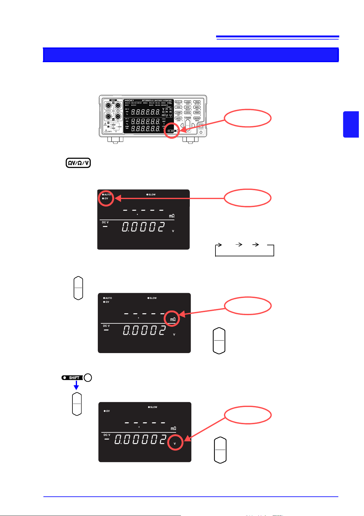
Instrument Settings
SHIFT not lit
The measurement mode changes each time
you press this key. Select Ω to measure only
resistance, or V to measure only voltage.
ΩV
Ω
V
ΩV lit
Increase the resistance measurement range.
Decrease the resistance measurement range.
mΩ lit
Increase the voltage measurement range.
Decrease the voltage measurement range.
V lit
23
3.2 Basic Measurement Example
5
6
Confirm the SHIFT lamp is not lit.
If this is lit, press the SHIFT key to turn it off.
3
Chapter 3 Measurement
Select the Resistance Measurement mode.
(Here, resistance and voltage measurement is selected.)
See "3.3 Selecting Measurement Mode" ( p.26).
7
8
Set the measurement range. (Here, 30 mΩ range is selected.)
See "3.4 Setting Measurement Range" ( p.27).
(SHIFT Lamp lit)
Set the voltage measurement range. (Here, the 6 V setting has been selected.)
See "Voltage measurement range" ( p.28)
Page 30
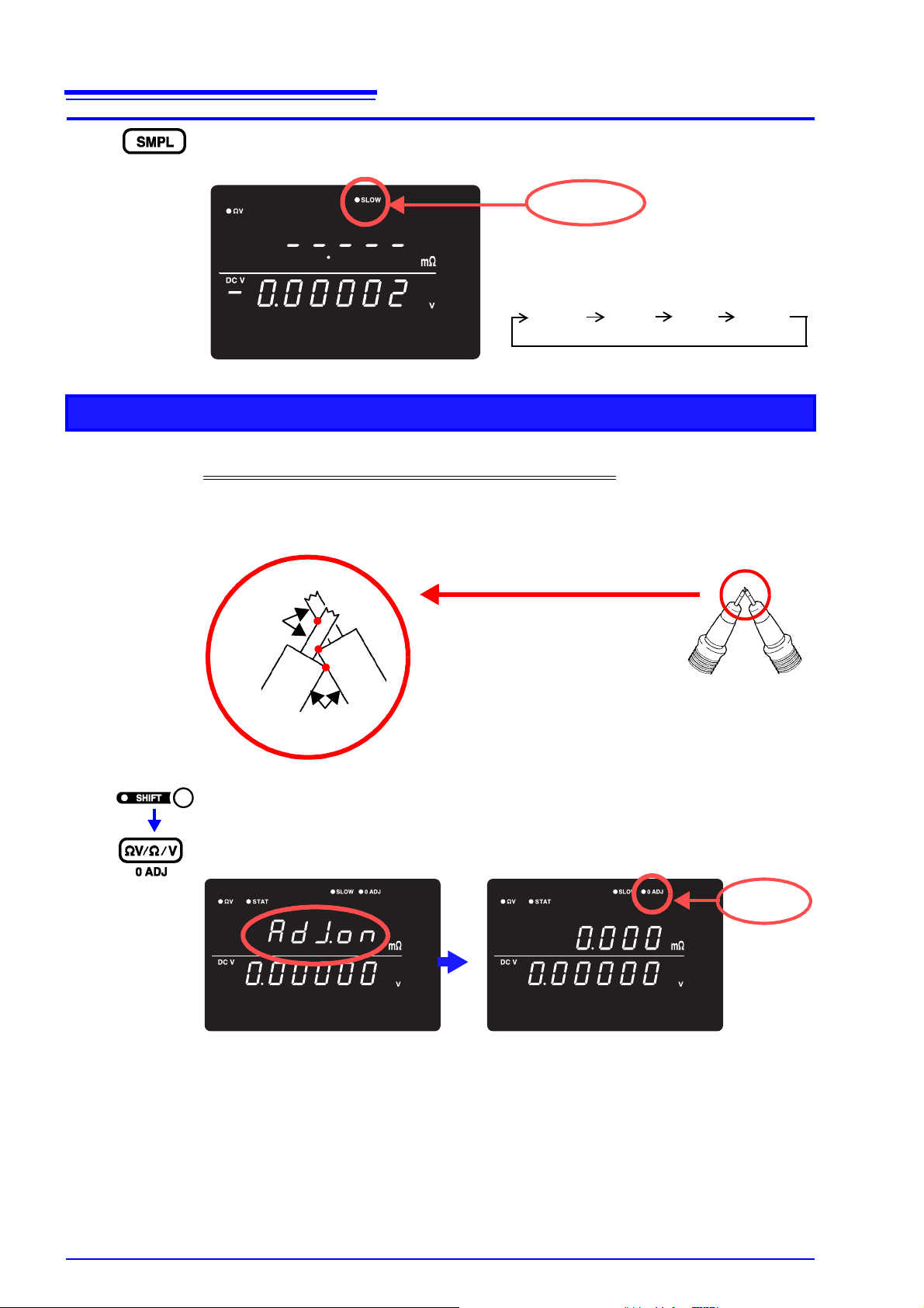
24
The sampling rate changes each time you
press this key.
EX.FAST
FAST
SLOW
MED
SLOW lit
Bring the pins into contact at 3 points.
• Internal conductor and internal condu cto r
• Internal conductor and external cond uct or
• External conductor and external conductor
Model 9770
Internal
conductor
External
conductor
0ADJ lit
3.2 Basic Measurement Example
9
Set the sampling rate. (Here, SLOW is selected.)
See "3.5 Setting Sampling Rate" ( p.30).
Zero-Adjustment
10
Short the test leads together.
Proper Zero-Adjustment is not possible with incorrect wiring.
See "3.6 Zero-Adjust Function" ( p.31).
Example: Model 9770 Pin Type Lead
11
(The SHIFT indicator lights up.)
Execute Zero-Adjust.
After zero-adjustment, the display returns to the measurement mode.
“Err.02” appears if Zero-Adjustment fails. Verify that the test lead tips are properly shorted,
and try zero-adjustment again.
Page 31

Measurement
Measured Resistance
Measured Voltage
25
3.2 Basic Measurement Example
12
13
Connect the test leads to a battery.
Open-terminal voltages for the instrument are as follows:
3 m
Ω and 30 mΩ ranges: 25 V peak
300 m
Ω range: 7 V peak
3
Ω to 3000 Ω: 4 V peak
These voltages derive from the load associated with charging the 1.2 uF
capacitor inside the instr um ent.
• The open-terminal voltage for the 3 m
4 V approximately 500 ms after the terminal is placed in the open state.
• When building a measurem ent line usin g scanner s, use a relay with a dielectric strength that is greater than or equa l to the open-terminal voltage for the
range being used.
Read the measured resistance and voltage.
3
Chapter 3 Measurement
Ω, 30 mΩ, and 300 mΩ ranges peaks at
See "3.7 Displaying Measurement Results" ( p.34).
See "10.3 Error Display" ( p.183).
Please refer to "Before returning for repair." of "Measured value is unstable." (
p.182) as a measurement and attention.
Page 32

26
SHIFT not lit
ΩV mode
(Resistance and Voltage measurement) measurement)
Ω mode
(Resistance measuremen t)
V mode
(Voltage measurement)
“Ω” or “mΩ” lit
“ΩV” indicates the
ΩV mode is selected
3.3 Selecting Measurement Mode
3.3 Selecting Measurement Mode
Select the measurement mode from ΩV (both resistance and voltage measurement), Ω (resistance measurement only) or V (voltage measurement only).
1
2
Confirm the SHIFT lamp is not lit.
If this is lit, press the SHIFT key to turn it off.
Switches the displayed measurement mode.
Each key-press switches the measurement mode.
The fastest measur ements are provided by selecting the Ω or V mode when
measuring resistance or voltage, respectively.
See " Sampling Time" ( p.174).
Page 33

27
Ω lit
mΩ lit
When the 3 Ω range is selected
When the 300 m
Ω range is
selected
Increase the resistance measurement range.
Decrease the resistance measurement range.
3.4 Setting Measurement Range
3.4 Setting Measurement Range
This section descr ibes how to set the measure ment range for resistanc e or voltage me asureme nt. For resi stance measurement, yo u ca n sel ect fr om s even r ang es from 3 mΩ to 3000 Ω. For volta ge me as ureme nt, y ou
can select from two ranges fro m 6 V to 60 V (for the Model BT35 62[-01]) or thr ee ranges f rom 6 V to 300 V
(for the Model BT3563[- 01]). There is also an auto-ran ge function , which determi nes the optimal range automatically.
Resistance measurement range
3
Chapter 3 Measurement
1
2
Select the resistance measurement range.
The position of the decimal point and unit of measure ment on the dis play wil l
be switched according to the selected range.
Select the range to use.
Pressing the up or down keys while in auto-range mode will cancel auto-ranging,
leaving the current measurement range as the manually set range.
Page 34

28
V lit
V lit
When the 60 V range is selected
When the 6 V range is
selected
Increase the voltage measurement range.
Decrease the voltage measurement range.
3.4 Setting Measurement Range
Voltage measurement range
1
Select the range to use.
2
ΩV lit
Select the voltage measurement range.
The position of th e d ec im al poi nt and uni t o f m eas urem ent on the di sp lay w il l
be switched according to the selected range.
Page 35

Auto-Ranging
AUTO lit
29
3.4 Setting Measurement Range
When manual range selection is enabled, pressing this enables auto-ranging.
The most suitable measurement range is then selected automatically.
3
Chapter 3 Measurement
The auto-range setting (on/off) for the ΩV function applies to both resistance and
voltage measurement.
Switching from
Auto
-ranging back to
Manual
range selection
Press the AUTO key again. The range can now be changed manually.
• Depending on the state of the test object, auto -ranging ma y be unstable. In
this case, select the range manually, or increase the Delay time.
• Auto-ranging is not available when Comparator or Memory functions are
enabled (ON).
• Refer to "Specifications" ( p.173) for details about accuracy.
Resistance Measurement Mode
Range Displayed Values
Measured Current Open-Terminal Voltage
3 mΩ -0.1000 to 3.1000 mΩ 100 mA
30 mΩ -1.000 to 31.000 mΩ 100 mA
300 mΩ -10.00 to 310.00 mΩ 10 mA
3 Ω -0.1000 to 3.1000 Ω 1 mA
30 Ω -1.000 to 31.000 Ω 100 μA
300 Ω -10.00 to 310.00 Ω 10 μA
3000 Ω -100.0 to 3100.0 kΩ 10 μA
About 4 Vpeak.
6 V -6.00000 v to ±6.00000 V -- --
60 V -60.0000 v to ±60.0000 V -- --
*1
300 V
-300.000 v to ±300.000 V -- --
*1: BT3563 only
Page 36

30
EX.FAST FAST MEDIUM SLOW
3.5 Setting Sampling Rate
3.5 Setting Sampling Rate
The sampling rat e can be selec ted fr om EX .FAST , FAST, M ED IUM and SLOW.
Slower sampling rates generally provide greater measurement precision.
Selects the sampling rate
• Measurements are es pecially susceptible to interference from the environment when EX.FAST is selected, so countermeasures such as shielding or
twisting of test leads, ca bles and wiring ar ound the test objec t may be necessary.
See "Appendix 1 Precautions for Making Custom Test Leads" ( p.1)
• When SLOW sampli ng is selected, self-ca libration is execut ed during each
measurement. At other sampling rates, self-calibration is executed manually
or automatically every 30 minutes.
See "4.10 Self-Calibration" ( p.69).
• Refer to the specifications for details of sampling rates.
See " Sampling Time" ( p.174).
Page 37

3.6 Zero-Adjust Function
Connection
Connection
SENSE-H SENSE-L
SOURCE-H SOURCE-L
at zero adjustment at measurement
Execute zero adjustme nt before measuring to nullify any res idual offset voltage
from the instrument or measurement environment. Measurement accuracy specifications are applicable after zero adjustment. Zero adjustment can also be executed by the 0ADJ terminal of the EXT I/O connector.
See "5.2 Signal Descriptions" ( p.76).
31
3.6 Zero-Adjust Function
Wiring Method for Zero-Adjustment
Before executing zero adjustment, connect the test leads (probes) as follows:
1. Connect SENSE-H to SENSE-L.
2. Connect SOURCE-H to SOURCE-L.
3. Connect the joined SENSE and SOURCE leads together as shown below.
Executing Zero-Adjustment
1
Position the measurement leads in the actual measurement state.
Since the amount of zero adju stment var ies wi th the posi tion and st at e of t he mea-
surement leads (probes) (i.e., their length, shape, position, etc.), the measurement leads must be position ed in the actual measurement state before performing
zero adjustment.
3
Chapter 3 Measurement
These variations are particularly pronounced in the 3 mΩ and 30 mΩ ranges, so
be sure to position the leads in same state as will be used to perform actual measurement when using those configurations.
Page 38

32
Red
SOURCE
SOURCE
SOURCE
SENSE
SENSE
SENSE
Correct
Incorrect
Red
Black
Black
SOURCE
SENSE
Bring the "V" marks together at the
same position.
Model 9770 (Option)
Model 9453 (Option)
Perform zero adjustment with
the alligator clips and lead rods
placed as above.
Internal
conductor
External
conductor
Bring the pins into contact
at 3 points.
Model L2100 (Option)
Each sensor pin has a line affixed to its base.
When using the zero-adjust feature, align
these lines in the same direction.
Model 9454
ZERO ADJUSTMENT BOAR
Line
0ADJ lit
3.6 Zero-Adjust Function
2
Short the test leads together.
Proper zero adjustment is not possible with incorrect wiring.
Example: Model 9287-10 CLIP TYPE LEAD
3
(The SHIFT indicator lights up.)
Zero-adjust display appears.
After measurement, the mea sured value of the compensati on applied by the zero-adjust
function is displayed.
The range of zero adjustment is up to 1000 dgt.
Page 39

Clearing Zero-Adjustment
(Main Display)
(Sub Display) flashing
(Main Display)
33
3.6 Zero-Adjust Function
1
2
If Err02 is displayed
(The SHIFT indicator lights up.)
The Menu display appears.
The zero-adjust value is cleared. (0ADJ not lit)
Indicates that zero adjustment could not be executed, either because the
range to be adjusted exce eds
exists.
The zero adj us t fu nc ti o n i s canceled, so repe at t he op e r at io n a f ter co rr ecting
the cause of the error.
• Zero adjustment is limited to ± 1000 dgt. (all ranges)
• Perform zero adjustment for each range that will be used in measurement.
• When using the auto-range function, perform zero adjustment for all ranges.
• When using the
according to the resistance measurement range zero-adjust state.
• Zero-adjustment values are retained even when power is turned off.
• The 0ADJ terminal of the EXT I/O connector also executes zero adjustment.
See "5.2 Signal Descriptions" ( p.76).
• Zero adjustment is very difficult with the delicate probe tips of the Model
L2100 and 9771 Pin Type Leads. Refer to " Wiring Method for Z ero-Adjustment" ( p.31) to use other leads when executing zero adjustment.
ΩV function, the 0ADJ indicator lights up or turns off
± 1000 dgt, or a measurement fault c ondition
3
Chapter 3 Measurement
Page 40

34
Measured Voltage
Measured Resist anc e
Measured Resistance
Measured Voltage
3.7 Displaying Measurement Results
3.7 Displaying Measurement Results
In the ΩV mode , resistance measurements appear on the upper display, and
voltage measurements appear on the lower display.
In the
Ω mode, resistance measurements appear on the upper display.
In the V mode, voltage measurements appear on the upper display.
Page 41

Measurement Fault Detection
If a measurement does not execute properly, a measurement fault
“- - - - -” is indicated on the display.
In addition, a measurem ent fault signal (ERR) is outpu t at the EXT I/O connector.
See " ERR Output" ( p.79).
A measurement fault is displayed in the following cases.
• When a test lead is not connected to the test object
• When the resistance of the measured object is over-range
Example: Attempting to measure 30 Ω with the 300 mΩ range selected.
• When there is a break in a probe wire
• When the contact resistance is high due to probe wear, dirt, or other factors,
or when the wiring resistance is high (see chart below)
• If the circuit protection fuse is blown
See "10.1 Troubleshooting" ( p.181).
Levels at which a measurement fault is detected
A measurement fault will result when the resistance values (contact resistance +
wiring resistance + test object resistance) between the source H and L or the
sense H and L leads is greater than or equal to the values in the following table:
35
3.7 Displaying Measurement Results
3
Chapter 3 Measurement
Range SOURCE H-L SENSE H-L
3 mΩ 3 Ω 3 Ω
30 m
Ω 3 Ω 3 Ω
300 m
Ω 20 Ω 20 Ω
3
Ω 200 Ω 20 Ω
30
Ω 2 kΩ 200 Ω
300
Ω 6 kΩ 2 kΩ
3000
Ω 6 kΩ 20 kΩ
*Large contact resistance and/or wiring resistance values may increase the error
component in measur ed value s. (Accurac y is not guar anteed when the sum of
contact resistance and wiring resistance is greater than or equal to 20 Ω [for the
3 mΩ and 30 mΩ ranges, 2 Ω].)
*The instrument may be unable to detect measure ment faults when the mea-
surement lead capacitance is greater than or equal to 1 nF.
Page 42

36
3.7 Displaying Measurement Results
Overflow Display
Overflow is indicate d by “OF” or “-OF” on t he display , caused by one of the fo llowing:
Display Condition
OF
-OF
• The measured value exceeds the limit of the current
measurement range
• The test object impedance exceeds the input level.
• When the result of relative value calculation is larger
than +99.999%.
• The measured value is below the limit of the current
measurement range
• The test object impedance exceeds the input level (in
the negative direction).
• When the result of relativ e value calculation is smaller
than -99.999%.
Page 43

37
Applied
Measurement Chapter 4
This chapter describes advanced operations employing the Comparator, Statistical Calculation and Memory functions.
Judge measurement values
against specified thresholds
Measure when trigger events occur Trigger Function
Output averaged measurement val-
ues
Display the results of calculation ex-
pressions applied to measurement
values
Store measurement values Memory Function
Lock the keys Key-Lock Function
Save measurement configurations Panel Save Function
Load saved measurement configura-
tions
Increase measurement precision Self-Calibration
Output measurement values via the
RS-232C interface according to trigger input timing
Comparator Function
Averaging Function
Statistical Calculation Functions
Panel Load Function
Measurement Value
Output Function
( p.38)
4
( p.55)
Chapter 4 Applied Measurement
( p.59)
( p.60)
( p.64)
( p.66)
( p.67)
( p.68)
( p.69)
( p.70)
Enable/disable ke y- pres s beeps Key Beeper Setting
Re-initialize the instrument Reset Function
( p.71)
( p.72)
Page 44

38
4.1 Comparator Function
4.1 Comparator Function
The comparator functi on compares measur ed values to prese t upper and lower
thresholds, judges the measurements according to their relative levels within the
preset range, and indicates the results of the comparisons.
Comparator thresholds can be set either by specifying upper and lower thr esholds, or by specifying a reference value and tolerance.
Comparator results ca n be indicated by the Hi, IN and Lo LEDs, beeper sound
and signal output at the EXT I/O connector.
See "Chapter 5 External Control (EXT I/O)" ( p.75).
The comparator setting process flow is as follows:
Display the comparator settings
1
Set the comparator judgment beeper
2
Select the comparator execution mode
3
(Auto or Manual/External)
Select resistance measurement
(If you do not need to configure resistance settings,
4
proceed to step 7.)
Select the resistance comparison method.
5
(absolute or relative value) for the comparator
Specify the resistance upper and lower thresholds
6
(or reference value and tolerance).
Select voltage measurement
7
Select the voltage comparison method
8
(absolute or relative value) for the comparator
Specify the voltage upper and lower thresholds
9
(or reference value and tolerance)
Apply your comparator settings
10
Enable the Comparator function
11
Page 45

4.1 Comparator Function
Example:
Set the upper and low er thresh olds for r esist an ce and volt age in the ΩV mode (300
mΩ range), and indicate whether the measurement value exceeds the upper or
lower thresholds by sounding the beeper.
Resistance : Upper threshold value 150.00 mΩ, Lower threshold value 100.00 mΩ
Voltage : Upper threshold value 15.2000 V, Lower threshold value 15.0000 V
COMP not lit
ΩV lit
Increase the resistance measurement range.
Decrease the resistance measurement range.
mΩ lit
V lit
Increase the resistance measurement range.
Decrease the resistance measurement range.
Comparator Setting Example 1 (Upper and Lower Threshold Judgment)
This example describes the comparator setting method.
1
Confirm that the Comparator function is OFF.
First make sure the Comparator function is disabled. Settings cannot be changed while
the Comparator function is enabled. Press the COMP key, if necessary, to disable the
Comparator function.
39
4
Chapter 4 Applied Measurement
2
3
4
Select the ΩV measurement mode.
Select the Resistance measur ement range (f or this ex ample, th e 300 mΩ range).
Select the voltage measurement range (for this exampl e, the 60 V range).
Page 46

40
oFF flashing
HL flashing
A flashing
r flashing
4.1 Comparator Function
5
6
The Comparator setting display appears.
Set the comparator judgment beeper (for this example, select HL).
oFF........no beeps sound
HL..........beeps repeatedly (when measurements are Hi or Lo)
in ...........beeps continuously (when measurements are IN)
btH1.......beeps continuously while measurements are within the thresholds (IN), and
beeps repeatedly when measurements are Hi or Lo.
btH2.......beeps once when measurements move into the threshold range (IN), and beeps
repeatedly when measurements go Hi or Lo.
7
8
Press so that the indicated position blinks, and select the comparator execution
mode (for this example, Auto).
A............ Auto Comparator (default setting)
E............ Manual Comparator
Press so that the indicated position blinks, and select resistance.
r.............Resistance
u ............Voltage
Page 47

41
HIGH & LOW flashing
Or
ten-keys
For this example,
Upper Threshold: 150 m
Ω
Upper Threshold: 100 mΩ
Select a digit
Select numerical value
Select a digit to change by moving the blinking location, then select the new numerical value.
Using the RANGE keys: Using the ten-keys:
Press the numeric keys corresponding to the digits to
be entered.
u flashing
4.1 Comparator Function
9
10
Press so that the indicated position blinks, and select the comparison method for
the comparator (here, HIGH/LOW).
HIGH, LOW..... Compare by upper and lower thresholds (default setting)
REF, % ............ Compare by reference value and tolerance
Switch to the upper/lower threshold setting display, and specify the thresholds.
4
Chapter 4 Applied Measurement
To enter the current measurement as the setting value: AUTO key
(Press on a screen other than the upper/lower threshold setting display.)
To enter the result of statistical calculation as the setting value: STAT key
(Press on a screen other than the upper/lower threshold setting display.)
See " Upper and Lowe r Th resho lds Se tti ng (b y Ref eren ce Value and Tolerance)" ( p.50).
Press so that the indicated position blinks, and sel ect voltage.
11
r.............Resistance
u............Voltage
Page 48

42
HIGH & LOW flashing
Or
ten-keys
For this example,
Upper Threshold: 15.2 V
Upper Threshold: 15 V
COMP lit
Measured Resistance
Judgment Result
Measured Voltage
Upper Threshold Value < Measured Value
Lower Threshold Value ≤
Measured Value ≤ Upper Threshold Value
Measured Value < Lower Threshold Value
4.1 Comparator Function
12
13
14
Press so that the indicated position blinks, and select the comparison method for
the comparator (here, HIGH/LOW).
HIGH, LOW.....Compare by upper and lower thresholds (default setting)
REF, %.............Compare by reference value and tolerance
Switch to the upper/lower threshold setti ng display, and specify the thresholds.
Applies setting and returns to the Measurement display.
The comparator function is enabled.
15
To cancel the settings: SHIFT key
Connect a test object and judge the measured value.
In the ΩV mode, you can verify comparator settings by pressing the VIEW key.
See
" Switching Between Measurement Value and Comparator Setting Displays" ( p.54).
Page 49

4.1 Comparator Function
Example:
Set a referen ce valu e and to lerance in the ΩV mode (3 Ω range), and set the beeper
to sound while measured values are within tolerance.
Resistance : Reference value 1.5 Ω, Tolerance 5%
Voltage : Reference value 4.2 V, Tolerance 0.5%
COMP not lit
ΩV lit
Increase the resistance measurement range.
Decrease the resistance measurement range.
Ω lit
• The upper and lower thre sholds are saved as the displa yed counts (inde pendent of measurement mode and range). Therefore, changing the measurement mode or range resu lts in the same di splay c ounts represen ting different
absolute values.
Example:
To specify the lower threshold as 150 m
Switching to the 3
old to 1.5
• The instrument can also base judgments on the absolute value of voltage
measured values (to prevent Lo judgments when the positive and negative
terminals are connected backwards).
See "Configuring the Absolute Value Judgment Function (Voltage)" ( p.51)
Ω.
Ω range after making this setting changes the lower thresh-
Ω in the 300 mΩ range, enter “15000”.
Comparator Setting Example 2 (Reference Value and Tolerance Judgment)
This example describes the comparator setting method.
43
4
Chapter 4 Applied Measurement
1
2
3
Confirm that the Comparator function is OFF.
First make sure the Comparator function is disabled. Settings cannot be changed while
the Comparator function is enabled. Press the COMP key, if necessary, to disable the
Comparator function.
Select the ΩV measurement mode.
Select the measurement range (for this example, the 3 Ω range).
Page 50

44
V lit
oFF flashing
in flashing
A flashing
4.1 Comparator Function
4
5
6
Select the voltage measurement range (for this example, the 6 V range).
The Comparator setting display appears.
Set the comparator judgment beeper (for this example, select In).
7
oFF........no beeps sound
HL..........beeps repeatedly (when measurements are Hi or Lo)
in ...........beeps continuously (when measurements are IN)
btH1.......beeps continuously while measurements are within the thresholds (IN), and
beeps repeatedly when measurements are Hi or Lo.
btH2.......beeps once when measurements move into the threshold range (IN), and beeps
repeatedly when measurements go Hi or Lo.
Press so that the indicated position blinks, and select the comparator execution
mode (for this example, Auto).
A............ Auto Comparator (default setting)
E............ Manual Comparator
Page 51

45
r flashing
REF & % flashing
Or
ten-keys
For this example,
Reference value: 1.5
Ω
Tolerance: 5%
Select a digit
Select numerical value
Select a digit to change by moving the blinking location, then select the new numerical value.
Using the RANGE keys: Using the ten-keys:
Press the numeric keys corresponding to the digits to
be entered.
4.1 Comparator Function
8
9
Press so that the indicated position blinks, and select resistance.
r.............Resistance
u............Voltage
Press so that the indicated position blinks, and select the comparison method for
the comparator (here, REF/%).
4
Chapter 4 Applied Measurement
HIGH, LOW..... Compare by upper and lower thresholds (default setting)
REF, % ............ Compare by reference value and tolerance
10
Switch to the Ref/% threshold setting display, and specify the thresholds.
To enter the current measurement as the setting value: AUTO key
(Press on a screen other than the upper/lower threshold setting display.)
To enter the result of statistical calculation as the setting value: STAT key
(Press on a screen other than the upper/lower threshold setting display.)
See " Upper and Lowe r Th resho lds Se tti ng (b y Ref eren ce Value and Tolerance)" ( p.50).
Page 52

46
u flashing
REF & % flashing
Or
ten-keys
For this example,
Reference value: 4.2 V
Tolerance: 0.5%
COMP lit
4.1 Comparator Function
11
12
Press so that the indicated position blinks, and select voltage.
r.............Resistance
u ............Voltage
Press so that the indicated position blinks, and select the comparison method for
the comparator (here, REF/%).
HIGH, LOW.....Compare by upper and lower thresholds (default setting)
REF, %.............Compare by reference value and tolerance
13
14
Switch to the Ref/% threshold setting dis play, and specify the thresholds.
Applies setting and returns to the Measurement display.
The comparator function is enabled.
To cancel the settings: SHIFT key
Page 53

47
Voltage measurements are displayed as their relative percentage offset
from the reference value (%)
Resistance measure men ts ar e displa ye d as
their relative percentage offset from the reference value (%)
Judgment Result
Measured resistance - Reference value
=
Reference value
x 100
Relative
percentage
Upper Threshold Value of setting range < Measured value
Lower Threshold Value of setting range ≤ Measured value ≤ Upper
Threshold Value of setting range
Measured value < Lower Threshold Value of setting range
4.1 Comparator Function
15
Connect a test object and judge the measured value.
In the ΩV mode, you can verify comparator settings by pressing the VIEW key.
See
" Switching Between Measurement Value and Comparator Setting Displays" ( p.54).
4
Chapter 4 Applied Measurement
The instrument can als o base judgment s on the absolu te value of voltag e measured values (to prevent Lo judgments when the positive and negative terminals
are connected backwards).
See "Configuring the Absolute Value Judgment Function (Voltage)" ( p.51)
Page 54

48
(Main Display)
(Main Display)
4.1 Comparator Function
Comparator Judgment Beeper Setting
Four beeper settings are available to audibly indicate comparator judgment results.
1
2
(The SHIFT indicator lights up.)
The Comparator setting display appears.
Set the comparator judgment beeper.
oFF........no beeps sound
HL..........beeps repeatedly (when measurements are Hi or Lo)
in ...........beeps continuously (when measurements are IN)
btH1.......beeps continuously while measurements are within the thresholds (IN), and
beeps repeatedly when measurements are Hi or Lo.
btH2.......beeps once when measurements move into the threshold range (IN), and beeps
repeatedly when measurements go Hi or Lo.
• The beeper does not sou nd when the comparator ju dgment beeper se tting
is disabled (oFF).
• The beeper does not sound when there is no judgment result.
See " Comparator Judgment Results" ( p.53).
Comparator Execution Mode Setting
Comparator judgment exec ution is selected by setting the auto or manual/exter nal comparator mode. Comparator judgment can be enabled and disabled by EXT I/O signals. Refer to Input Signals (Page 77).
(The SHIFT indicator lights up.)
1
The Comparator setting display appears.
2
Press so that the indicated position blinks, and set the comparator execution
mode.
A............Auto comparator (comparator results are always output [default setting])
E............Manual comparator (comparator results are output only when the MANU EXT I/
O input is enabled [ON])
The auto setting is appropriate for normal use. Use the manual/external setting
when you need to control comparator judgment timing.
Page 55

Comparator Threshold Method Selection
Two methods are available for setting comparator thresholds.
49
4.1 Comparator Function
1
2
(The SHIFT indicator lights up.)
The Comparator setting display appears.
Press so that the indicated position blinks, and set the comparator threshold
method.
4
Chapter 4 Applied Measurement
HIGH, LOW..... Compare against specified upper and lower thresholds (default setting
method)
REF, % ............ Compare against upper and lower thresholds internally calculated from a
specified reference value and tolerance
About comparisons based on a reference value and tolerance
When the reference value and tolerance method is selected, thresholds are calculated as
follows:
Upper threshold = reference value X (100 + tolerance [%]) / 100
Lower threshold = reference value X (100 - tolerance [%]) / 100
Measured values a re displayed as a percentage relative to the reference value, calculated as follows:
Relative value = (measured value - reference value) / reference value X 100 [%]
Page 56

50
Or
ten-keys
For example,
Upper Threshold: 150 m
Ω
Lower Threshold: 100 mΩ
Select a digit
Select numerical value
Select a digit to change by moving the blinking location, then select the new numerical value.
Using the RANGE keys: Using the ten-keys:
Press the numeric keys corresponding to the digits to
be entered.
4.1 Comparator Function
Upper and Lower Thresholds Setting
(by Reference Value and Tolerance)
1
2
3
(The SHIFT indicator lights up.)
The Comparator setting display appears.
Press so that the indicated position blinks, and select resistance or voltage.
r.............Resistance
u ............Voltage
Select the threshold setting display, and enter upper and lower threshold values.
Page 57

4.1 Comparator Function
To enter the current measurement as the setting value: AUTO key
Press on a screen other than the upper/lower threshold (reference value/tolerance) setting displ ay. This key is used as a numeric key on the up per/lower
threshold (reference value/tolerance) setting display.
The current measurement v alu e is set as th e uppe r or lower thres ho ld ( duri ng
upper/lower threshold setting), or as the reference value (during reference
value and tolerance setting). If the measured value is faulty or
ignored (not entered).
To enter a statistical calculation result as the setting value: STAT key
Press on a screen other than the upper/lower threshold (reference value/tolerance) setting displ ay. This key is used as a numeric key on the up per/lower
threshold (reference value/tolerance) setting display.
The result of statistical calculation is set as follows:
± OF, it is
51
During upper/lower
threshold setting
During reference value
and tolerance setting
Where “
No setting occurs if statistical calculation is disabled and no statistical calcula-
tion result exists.
See "4.5 Statistical Calculation Functions" ( p.60).
Setting thresholds from the AUTO and ST AT keys is possible only when the
selected (blinking) character is non-numeric.
Threshold and reference values can be set from 0 to 99999 (or 999999 for voltage), and toleranc e can be set from 0.000 to 99.999 %. Negative values are
not settable. E ntries using statistical c alculation results that exceed the valid
range are restricted to the range limit.
σ” represents population standard deviation (σ
Upper threshold = average value + 3
Lower threshold = average value - 3σ
Reference value = average value
Tolerance = 3
σ / average value X 100%
Configuring the Absolute Value Judgment Function (Voltage)
This section descri bes how to configure functionality for acqui ring the absolute
value of the voltage measured value when judging comparators, allowing a judgment to be made based on the absolute value of the volta ge even if polar ity is
reversed when the probes are connected to the battery.
σ
4
Chapter 4 Applied Measurement
).
n
1
Ordinarily, conne cting th e probes wi th the pol arity r ever sed resu lts in a negativ e
voltage measured valu e, yi eldin g a Lo comp arato r judgm ent re sult. To g enera te
an IN judgment whenever the reading falls within the specified range, even if the
probes have been conne cted backwards (resulting in a negative volta ge measured value), set the absolute value judgment function to "On."
This function is configured on the menu screen.
(The SHIFT indicator lights up.)
The menu screen is displayed.
Page 58

52
COMP lit
4.1 Comparator Function
2
Display the absolute value judgment function configuration screen.
See "1.4 Menu Display Sequence (SHIFT → ENTER)" ( p.13)
3
Set the absolute value judgment function to either "On" or "Off."
on
.........................
oFF...................Absolute value judgment function off.
Accept the setting and return to the measurement screen.
Absolute value judgment function on.
4
For example, the following judgment results would be obtained when connecting
the probes backwards to a 3.7 V battery (resulting in a displayed voltage measured value of -3.7 V) with an upper threshold of 3.9 V and a lower threshold of
3.6 V:
Absolute value judgment function off: Lo
Absolute value judgment function on: IN
Enabling and Disabling the Comparator Function
Enables the comparator
When the comparator i s enable d, the foll owing key o perations a re disable d
to avoid inadvertent operations.
ΩV/Ω/V key (Measurement mode setting)
•
• SHIFT
• SHIFT
• AUTO key (Auto-ranging setting)
• SMPL key (Sampling rate setting)
• SHIFT
• SHIFT
• SHIFT
• SHIFT
• Range keys
When the comparator is enabled, auto-ranging is automatically disabled.
→ ΩV/Ω/V key (Zero-Adjustment)
→ COMP key (Comparator setting)
→ SMPL key (Averaging setting)
→ TRIG key (Trigger source setting)
→ ENTER key (Menu display)
→ STAT key (Delay setting)
Page 59

53
Upper Threshold Value < Measured Value
Lower Threshold Value ≤ Measured Value ≤ Upper Threshold Value
Measured Value < Lower Threshold Value
Ω : Resistance
V : Measurement
4.1 Comparator Function
Comparator Judgment Results
Resistance and voltage measurements are judged independently. Both judgment results are indicated on the display.
Judgment Operation The comparator c ompares measured values with the p reset threshold values,
and judges whether the measurement is within the thr esholds. Resistance and
voltage measurements are judged independently.
The absolute value of the measurement is compared to the upper and lower
thresholds.
When the absolute value judgment function is on, the absolute value of the measured value is compared to the upper and lower thresholds.
4
Chapter 4 Applied Measurement
PASS/FAIL
Judgment Output
Measurement fault values are judged as follows:
Display Judgment
- - - - -
OF
-OF
Judgment results (Hi, IN or Lo for both resistance and voltage) are output to EXT
I/O connecto rs.
Additionally, the in strument can generate PAS S/FAIL judgment output to facilitate easy judgme nts. In this configuration , i t ou tputs a PASS judgment when t he
resistance and voltage are both IN and otherwise a FAIL judgment.
See " Output Signals" ( p.78).
With the relative valu e com parison method (thr esholds defin ed by a ref erence
value and toleranc e), the upper an d lower thre sholds are c alculated inter nally
for comparison w ith me asur ements . There fore, even if a rela tive display value
is equal to a judgment threshold (tolerance limit), it may be judged Hi or Lo.
No judgment
Hi (exceeds the upper threshold)
Lo (less than the lower threshold)
Page 60

54
Example:
Resistance: Upper threshold value 150.00 mΩ, Lower threshold value 100.00 mΩ
Voltage: Upper threshold value 15.2000 V, Lower threshold value 15.0000 V
Resistance and voltage measurement display
(Shows resistance and voltage measurement values simultaneously)
Resistance measurement and comparator
display (Shows resistance measurement and
resistance comparator setting values)
Voltage measurement and comparator display (Shows voltage measurement and voltage comparator setting values)
4.1 Comparator Function
Switching Between Measurement Value and Comparator Setting Displays
In ΩV mode, both resistance and voltage measurement values are displayed.
Although comparator setting values are not normally displayed when the comparator is enabled , they can b e dis playe d for conf irma tion by the dis play s witching function.
Press this key to switch the display between measurement values
and comparator setting values.
Measurement display switching is available only with the comparator
enabled, and in the ΩV mode.
Use it to confirm comparator setting values.
Page 61

4.2 Trigger Function
EXT TRIG lit
Trigger Source Settings
Two trigger sources are available: internal and external.
Internal Trigger Trigger signals are automatically generated internally.
External Trigger Trigger signals are provided externally or manually.
(The SHIFT indicator lights up.)
55
4.2 Trigger Function
(free-run)
Measurement with
External Triggering
Switches the selected trigger source.
EXT.TRIG lit................. External triggering is selected.
EXT.TRIG not lit........... Internal triggering is selected.
An external trigger can be applied in three ways.
• Applying a trigger manually by operating key
Pressing the TRIG key causes one measurement.
• Applying a trigger at the EXT I/O connector
Grounding the TRIG
causes one measurement.
See " Input Signals" ( p.77).
• Applying a trigger through RS-232C or GP-IB interface
Sending the
measurement.
∗TRG command via the RS-232C or GP-IB interface causes one
terminal of the EXT I/O connector on the rear panel
4
Chapter 4 Applied Measurement
• When Internal triggeri ng is e nab led, e xternal inpu t at th e EX T I/O TRIG terminal and the
• The normal state of operation with the front panel controls is continuous
measurement. Setting the trigger source to Internal enables the free-run
condition in which triggering occurs continuously. When the trigger source is
set to External, a measurement occurs each time an external trigger is
applied. Continuous mea surement can be disabled via RS -232C or GP-IB
interface signals, i n whic h case trigg ering oc curs on ly when signa led by the
external host (PC or PLC).
See " Triggering System Description" ( p.146) .
∗TRG command are ignored.
Page 62

56
(Main Display)
(Sub Display)
The current setting blinks.
(Sub Display)
(Sub Display)
Or ten-keys
(Sub Display)
4.2 Trigger Function
Trigger Delay Settings
Specify the delay from the moment a trig ger is applied to the s tart of measurement. By us ing this function,
even when a trigger is applied i mmediately after connecting a test object, the start of measurement can be
delayed to allow sufficient time for the measurement value to stabilize. Trigger delay can be set with 1 ms resolution from 0.000 to 9.999 seconds.
(The SHIFT indicator lights up.)
1
The Trigger Delay setti ng display appears.
2
Select ON.
3
The numerals indicating the trigger del ay blink.
4
Set the trigger delay.
5
Disabling the Trigger Delay Function
Applies setting and returns to the Measurement display.
To cancel the settings:
(The SHIFT indicator lights up.)
1
SHIFT key
2
3
The Trigger Delay setti ng display appears.
Select OFF.
The Trigger Delay is disabled.
Page 63

57
4.3 Measurement Current Pulse Output Function
4.3 Measurement Current Pulse Output Function
When using multipl e instruments to take measur ements at the same time, you
may experience interfer ence as a result of ele ctromagnetic in duction caused by
the devices' measurement currents, causing measured values to gradually oscillate between increasi ngly large values. To prevent this phenomenon, the measurement current p ulse output function can be used to appl y the measurement
current only while m easurement is being performed. (This funct ionality is only
available during external trigger measurement or while continuous measurement
is off.)
When this function is t urned on, the m easurement curr ent is only appl ied at the
time of measurement. By staggering the timing of trigger measurement, measurement current interference can be eliminated.
4
1
2
3
4
(The SHIFT indicator lights up.)
The menu screen is displayed.
Display the measurement current pulse function configuration screen.
See "1.4 Menu Display Sequence (SHIFT → ENTER)" ( p.13)
Set the constant current pulse function to either "On" or "Off."
on.................... Measurement current pulse function on.
oFF.................. Measurement current pulse function off.
Accept the setting and return to the measurement screen.
Chapter 4 Applied Measurement
Page 64

58
Measurement processing triggered by external TRIG signal or "READ?" command
Applied only during measurement (including trigger delay time).
Measurement current is applied continuously.
Measurement and current application when using external trigger measurement
or when continuous measurement is off (:INIT:CONT OFF)
Measurement current application when using normal internal trigger measurement
(The measurement current is applied continuously when measurement current pulse mode is off.)
Measurement
Measurement
Measurement
Measurement
current
current
4.3 Measurement Current Pulse Output Function
Measurement current application timing when measurement current pulse mode is on
When the measureme nt curr ent pulse ou tput fun ction is on, th e belo w is adde d
to the sampling time.
When using the ΩV mode: +1 ms
When using the Ω mode: +4 ms
Page 65

59
(Main Display)
(Sub Display)
The current setting blinks.
(Sub Display)
Or
ten-keys
(Sub Display)
4.4 Averaging Function
4.4 Averaging Function
The Averaging Function av erages measurement values for outp ut. This function can minimize instabilit y of
displayed values. The number of samples to average can be set from 2 to 16.
1
2
3
4
(The SHIFT indicator lights up.)
The Averaging Function setting display appears.
Select ON.
The number of samples to average setting blinks.
Select the number of samples to average.
4
Chapter 4 Applied Measurement
5
The Average Measurement display appears. (AVG lit)
To cancel the settings:
Disabling the Averaging Function
1
(The SHIFT indicator lights up.)
The Averaging Function setting display appears.
Select OFF.
2
3
The Averaging Function is disabled. (AVG not lit)
When the internal trigger is used for cont inuous measurement ( free-run), the
display shows th e moving av erag e. Otherwi se, the d ispl ay sho ws the in tegrating average.
See "4.2 Trigger Function" ( p.55).
SHIFT key
Page 66

60
n
x
x
=
n
xnx
−
=
22
σ
1
22
−
−
=
n
xnx
s
16−
−
=
n
LoHi
Cp
σ
1
6
2
−
−+−−
=
n
xLoHiLoHi
CpK
σ
4.5 Statistical Calculation Functions
4.5 Statistical Calculation Functions
The mean, maximum, minimum, standard deviation of population, standard deviation of sample and process capability ind ices are cal culated and d isplayed for
up to 30000 measurement values.
The calculation formulas are as follows:
Mean
Standard deviation of population
Standard deviation of sample (=
Process capability index (dispersion)
Process capability index (bias)
• In these formulas, n represents the number of valid data samples.
• Hi and Lo are the upper and lower thresholds of the comparator.
• The process capability indices represent the quality achievement capability
created by a process, wh ich is the breadth of the dispers ion and bias of the
process' quality. Generally, depending on the values of Cp and CpK, proce ss
capability is evaluated as follows:
Cp, CpK>1.33........................ Process capability is ideal
1.33 ≥ Cp, CpK>1.00............. Process capability is adequate
1.00 ≥ Cp, CpK...................... Process capability is inadequate
(=
σ
)
n
σ
)
n-1
• When only one val id data sample exists, standar d deviation of sam ple and
process capability indices are not displayed.
• When
• The upper limit o f Cp and CpK is 9 9.99. Values of Cp and CpK>99.99 are
• Negative values of CpK are handled as CpK=0.
• When comparator, range or auto-ranging settings are changed while statisti-
• When normal measurement values and relative display values (%) are
σ
is 0, Cp and CpK are 99.99.
n-1
displayed as 99.99.
cal data is displayed, the display of Cp and CpK values changes to “- - . - -”.
mixed, correct calculation results cannot be obtained.
Page 67

4.5 Statistical Calculation Functions
(Main Display)
(Sub Display)
(Sub Display)
(Main Display)
(Sub Display)
(Sub Display)
Enabling/Disabling the Statistical Calculation Function
61
1
2
(press three times)
3
The Statistical Calculation display appears.
The function enable/disable display appears.
Enable or disable the Calculation Function on the Sub Display.
on.......... enables the calculation function on.
oFF ....... disables the calculation function off.
Applies setting and returns to the Measurement display.
To cancel the settings:
• Statistical Calculation function setting (ON, OFF) is not av ailable when the
Comparator is enabled.
• If Statistical Calculati on is turned off and then back on without fir st clearing
calculation results, it re sumes c alculating from the poin t when it was tu rned
off.
• The Statistical Calculation function slows measurements when it is ON.
SHIFT key
4
Chapter 4 Applied Measurement
Clearing Statistical Calculation Results
1
The Statistical Calculation display appears.
2
The Clearing screen will appear.
(press once)
Clears statistical cal culation results.
3
Page 68

62
(Main Display)
(Sub Display)
(Sub Display)
4.5 Statistical Calculation Functions
Automatic Clearing of Statistical Calculation Results after Printi ng
The instrument can be set to automatic ally clear stati stical calcu lation results after results are output to the
printer.
1
2
3
4
(Press twice)
The Statistical Calculation display appears.
Bring up Auto Clearing After Printing in the Setup screen.
Turn Automatic Clearing After Printing on or off.
on.......... Automatically clears statistical calculation results after they are
output to the printer.
oFF........ Does not clear the results themselves.
Applies setting and returns to the Measurement display.
To cancel the settings:
SHIFT key
Importing Data
Pressing the TRIG key while Statistical Calculati on is ON executes one of the following operations:
• External Trigger: Tak es one measure ment and perfo rms statistical c alculation on the result
• Internal Trigger: Performs statistical calculation on the value displayed
immediately after pressing
• ∗TRG command executes the same operation.
• Grounding the TRIG
operation.
terminal of the EXT I /O connector ex ecutes the same
Confirming Statistical Calculation Results
1
The Statistical Calculation display appears.
2
The indication on the display changes as follows with each key-press.
Page 69

Example: when the ΩV mode is selected
Valid data
Mean
Maximum
Data Sample
No.
Minimum
Data Sample
Cp
CpK
Total data count of voltage measurement
Mean of voltage measurement
Maximum of voltage
measurement
Minimum of vo ltage
measurement
Standard deviation of
population of voltage
Standard deviation of
sample of voltage
measurement
Process capability indices
of voltage measurement
(not displayed in Ω mode)
(not displayed in V mode)
Total data count of resistance me asurement
Mean of resistance measurement Maximum of resistance measurement
63
4.5 Statistical Calculation Functions
Minimum of resistance measurement Standard deviation of population
of resistance measurement
Process capabilit y ind ice s of r esist anc e
measurement
ON/OFF setting Auto Clearing After Printing setup Clear setup
Standard deviation of sample of resistance measurement
4
Chapter 4 Applied Measurement
Sending Statistical Calculation Results to the Printer
• When a valid data count (meas urement fault other than ± OF) is zero, no
calculation result is displayed.
• When only one valid data s ample exists, standard deviation of sa mple and
process capability indices cannot be displayed.
• When comparator, range or auto-ranging settings are changed while statistical data is displayed, the display of Cp and CpK values changes to “- - . - -”.
With the statistical calculation results displayed, press the PRINT key.
The statistical calculation results are output to the optional printer.
See "Chapter 6 Printer (Optional)" ( p.87).
Page 70

64
MEM lit
MEM lit
4.6 Memory Function
4.6 Memory Function
The Memory function is only available via communication commands.
When the Memory fun ction is enabled, measurement values are stored in the
instrument’s internal memory according to trigger input sequence (up to 400 values). Stored data can be downloaded later upon command.
When measuring usi ng a scanner to s witch multipl e test obje cts, switch ing time
can be quite long if m easurement value s are downloaded to the PC after each
measurement. Test cy cle time can be minimized by using this function to st ore
measurement value s internally until all chan nel measurements are finis hed, at
which time the stored values are downloaded together during the next idle
period.
1
2
3
4
Select the RS-232C or GP-IB interface.
See " Selecting the Interface" ( p.101).
Send the command to enable the Memory function.
:MEMory:STATe ON
The MEM indicator lights.
Measurement values are stored.
When a trigger is applied by the TRIG key, TRIG EXT I/O input signal or
TRG command, the MEM indicator blinks once and the measured value is
∗
stored.
If an external trigger source is selected, one measurement is stored after
each trigger event. In the internal triggering case, the first measurement value after triggering is stored. Apply a trigger as many times as is necessary.
Page 71

65
4.6 Memory Function
5
Send the command to download the data from memory.
:MEMory:DATA?
The stored measurement values are returned in response.
:MEM:DATA?
1, 290.60E-3, 1.3924E+0
2, 290.54E-3, 1.3924E+0
3, 290.50E-3, 1.3923E+0
4, 290.43E-3, 1.3923E+0
5, 290.34E-3, 1.3924E+0
END
The “END” character is sent as the last line of the data.
To download stored data one measurement at a time, send this command:
:MEMory:DATA? STEP
The instrument sends one stored data object and enters the wait state.
When the instrument receives an “N” from the PC or other device, the next
stored data object is sent.
Repeat until the last data object is downloaded.
When all stored data has been downloaded, the instrument sends an “END”
character.
:MEM:DATA? STEP
1, 290.60E-3, 1.3924E+0
N (sent from PC)
2, 290.54E-3, 1.3924E+0
N (sent from PC)
3, 290.50E-3, 1.3923E+0
N (sent from PC)
4, 290.43E-3, 1.3923E+0
N (sent from PC)
5, 290.34E-3, 1.3924E+0
N (sent from PC)
END
4
Chapter 4 Applied Measurement
6
To clear the instrument's memory, send it the following command.
:MEMory:CLEAr
Unless the memory is cleared, measurement data continues to be stored
upon each trigger event.
• The instrument's memo ry st or age capaci ty is 400 m eas urements. Be aware
that attempting to store m ore data (by applying a tr igger) results in no thing
further being stored.
• Refer to Chapter 8 RS-232C/GP-IB Interfaces (Page 97),
for details about the communication methods and sending and receiving
commands.
• When the Memory function is enabled, auto-ranging is not available.
• Memory contents are cleared when performing the following operations:
When enabling the Memory function (off to on)
When changing the measuremen t range
When changing comparator settings
When sending the
When Reset is executed from the menu display
When sending ∗
When sending :SYSTem:RESet
When turning power on
:Memory:Clear command
RST
Page 72

66
LOCK lit
4.7 Key-Lock Function
Disabling the Memory Function
1
2
Send the command to enable the Memory function Off.
:MEMory:STATe OFF
The Memory function is disabled. (MEM not lit)
4.7 Key-Lock Function
Executing Key-Lo ck disables the opera ting keys on the front of the i nstrument.
This function can be useful for protecting settings.
(The SHIFT indicator lights up.)
Enable the Key-Lock function.
Disabling Key-Lock
• Even if the power s upply is interrupted, the Key-Lock function is not canceled.
•The TRIG key remains operational.
(The SHIFT indicator lights up.)
Disable the Key-Lock function. (LOCK is not lit)
When communicating by remote control, the remote control status is canceled.
Page 73

4.8 Panel Save Function
(Main Display)
(Sub Display)
The panel number blinks.
Or
ten-keys
(Sub Display)
(To save measurement settings as Panel No. 3)
The current measurement setting state is stored (saved) in non-volatile memory.
Up to 126 sets of measurement states can be saved.
The measurement settings (state) at the time this function is executed are
saved.
Saved measurement states can be reloaded using the Panel Load function,
described later.
67
4.8 Panel Save Function
1
2
3
(The SHIFT indicator lights up.)
The Panel Saving display appears.
Select the panel number to save.
When selecting a saved panel, “USEd” is displaye d .
Saves the measurement setting state and returns to the Measurement display.
To cancel the settings:
SHIFT key
4
Chapter 4 Applied Measurement
Saved Items
• If you select a Panel number that was previously saved and press the
ENTER key, the contents are overwritten.
• The Key-Lock state can be saved only by the
command.
• Measurement mode setting • Switching displays setting
• Range setting • Delay setting
• Auto-ranging settin g • Zero-Adjust settin g
• Sampling rate setting • Averaging setting
• Comparator settings • Key-Lock
• Internal/External trigger setting • Statistical Calculation setting
(The absolute value judgment function setting is not saved.)
:SYSTem:SAVE remote
Page 74

68
(Main Display)
(Sub Display)
The panel number blinks.
Or
ten-keys
(Sub Display)
(To load measurement settings from Panel No.3)
4.9 Panel Load Function
4.9 Panel Load Function
Loads the measurement settings saved by the Panel Save function from internal
non-volatile memory.
1
2
3
The Panel Loading display appears.
Select the panel number to load.
Loads the measurement setting state and returns to the Measurement
display.
To cancel the settings:
• If an unsaved Panel No. is selected, a warning beep sounds when you
press ENTER key.
• When selecting a Pane l No. with the up/down RANGE keys, only the numbers of previously saved panels appear.
• Loading can also be executed using the TRIG
LOAD6
See " Input Signals" ( p.77).
pins of the EXT I/O interface.
SHIFT key
signal and the LOAD0 to
Page 75

4.10 Self-Calibration
(Main Display)
(Sub Display)
The current setting blinks.
The self-calibration function adjusts offset voltage and gain drift of the instrument’s internal circuitry to improve measurement precision.
The instrumen t’s measurement accuracy s pecifications depend o n self-calibration, so it must be executed frequently. In particular, always execute self-calibration after warm-up and wh en the ambient temperature changes by m ore than
°C. However, regardless of this setting, self-calibration is executed during
2
every measurement when SLOW sampling is used.
Self-calibration can be executed by the following two methods:
69
4.10 Self-Calibration
1
2
Auto Executes self-calibration automatically once every 30 min-
utes.
Manual Self-calibr ation can b e execut ed manual ly by applying a CA L
input signal (grounding t he CAL termin al of the EXT I/O c onnector).
It can also be executed with the SYSTem:CALibration command.
(The SHIFT indicator lights up.)
The Menu display appears.
The Self-Calibration setting display appears.
See "1.4 Menu Display Sequence (SHIFT → ENTER)" ( p.13).
p.140)
(
4
Chapter 4 Applied Measurement
3
4
Self-calibration r equires about 55 ms, during whi ch measurement processing
is temporarily suspe nde d.
Select Auto or Manual on the Sub Display.
AUto..... Auto self-calibration
in........... Manual self-calibration
Applies setting and returns to the Measurement display.
Page 76

70
(Main Display)
(Sub Display)
The current setting blinks.
4.11 Measurement Value Output Function
4.11 Measurement Value Output Function
This function causes output of measured values via the RS-232C interface in the
same sequence as trigger input.
This function is useful when measuring u sing internal (free-ru n) triggering, and
for obtaining measured values on a PC when using a fo otswitch for triggering.
1
2
3
4
(The SHIFT indicator lights up.)
The Menu display appears.
The Measurement Value Output function setting display appears.
See "1.4 Menu Display Sequence (SHIFT → ENTER)" ( p.13).
Turn Measurement Value Output Function on or off.
on.......... enables the measurement value output function on.
oFF........disables the measurement value output function off.
Applies setting and returns to the Measurement display.
5
The measured value is output from the RS-232C interface when you
press the
terminal.
Set the PC to the receiving state beforehand. When a measurement
value is received, the PC should perform appropriate processing
such as recording or displaying, then re-enable the receiving state.
• When external trigger ing is enabled, a measurement is performed and the
value is sent after eac h trigger event. When inter nal triggering is enable d,
the first value measured after triggering is sent.
• The measurement output function is not applicable to the GP-IB interface or
printer.
TRIG key or when a signal is applied to the EXT I/O TRIG
Page 77

4.12 Key Beeper Setting
(Main Display)
(Sub Display)
The current setting blinks.
Select whether a bee p sounds w hen an o perating ke y on the front of the in strument is pressed.
71
4.12 Key Beeper Setting
1
2
3
4
(The SHIFT indicator lights up.)
The Menu display appears.
The Key Beeper setting display appears.
See "1.4 Menu Display Sequence (SHIFT → ENTER)" ( p.13).
Select the key beeper state on the Sub Display.
on.......... Key beeper enabled.
oFF ....... Key beeper disabled.
Applies setting and returns to the Measurement display.
4
Chapter 4 Applied Measurement
Page 78

72
(Main Display)
(Sub Display)
The current setting blinks.
(Sub Display)
When SYS (system reset) is selected
4.13 Reset Function
4.13 Reset Function
The reset function can be used to re-initialize current measurement settings
(excluding saved panel data) to their fact ory defaults, or to re- initialize all measurement settings including saved panel data to factory defaults.
1
2
3
4
(The SHIFT indicator lights up.)
The Menu display appears.
The Reset display appears.
See "1.4 Menu Display Sequence (SHIFT → ENTER)" ( p.13).
Select the Reset method on the Sub Display.
SEt........ Reset (initializes measurement settings other than those stored
with Panel Save)
SYS....... System Reset (initialize all measurement settings)
ENTER blinks.
5
Executes the Reset.
To cancel the settings:
System Reset also initializes Panel Save data.
SHIFT key
Page 79

Initial Factory Default Settings
Description Default
Measurement Mode
73
4.13 Reset Function
ΩV
Resistance Measurement Range
Voltage Measurement Range 6 V
Auto Range ON
Zero-Adjust OFF
Delay OFF
Delay Time 0.000s
Sampling Rate SLOW
Averaging Function OFF
Average Times 2
Self-Calibration AUTO
Continuous Measurement ON
Trigger Source Internal trigger
Line Frequency AUTO
Key Beeper Setting ON
Key-Lock Function OFF
Comparator OFF
Comparator Threshold Method
(resistance and voltage)
3 mΩ
Hi, Lo
4
Chapter 4 Applied Measurement
Comparator Upper Threshold
(resistance and voltage)
Comparator Lower Threshold
(resistance and voltage)
Comparator Judgment Beeper OFF
Comparator Execution Mode AUTO
Statistical Calculation Functions OFF
Automatic Clearing of Statistical
Calculation Results
Interface RS-232C
Baud Rate 9600 bps
GP-IB Address 1
GP-IB Delimit er LF
Print Interval 0 (The interval print disabled)
Error Output ASync
Measurement Value Output Function OFF
EOM Output
EOM Pulse Width 1 ms
0
0
OFF
HOLD
Measurem ent current pulse function OFF
Comparator absolute value judgment function
OFF
Page 80

74
4.13 Reset Function
Page 81

5.1 Overview
External Control
(EXT I/O) Chapter 5
5.1 Overview
75
External Control
Input Functions
External Output
Terminal Functions
• External trigger input (TRIG)
• Select Panel No. to load (LOAD0
• Zero-adjust signal input (0ADJ
• Print Signal input (PRINT
• Self-calibration signal input (CAL
• Manual comparator judgment input (MANU
• End-of-Conversion signal output (EOM)
• Reference signal output (INDEX
• Measurement Fault signal output (ERR
• Comparator decision signal outp ut (R-Hi
FAIL
)
T o avoid electric shock or damage to the equipment, always observe the
following precautions when connecting to the EXT I/O terminals.
• Alway s turn off the power to the instrument and to any devices to be
connected before making connections.
• Dur ing operation, a wire becoming dislocated and contacting another
conductive object can be serious hazard. Make sure that connections
are secure and use screws to secure the external connectors.
• E nsure that devices and systems to be connected to the EXT I/O ter-
minals are properly isolated.
)
to LOAD6)
)
)
)
)
)
, R-IN, R-Lo, V-Hi, V-IN, V-Lo, PASS,
5
Chapter 5 External Control (EXT I/O)
To avoid damage to the instrument, observe the following cautions:
• Do not apply voltage o r curren t to the EX T I/O term inals that e xceeds their
ratings.
• When driving r elay s, b e su re t o ins tall di odes to a bsor b co unter-el ectr omo-
tive force.
Be careful not to short-circuit ISO_5V to ISO_COM.
•
See: "5.2 Signal Descriptions" ( p.76)
Page 82

76
EXT I/O Connector (Instrument Side)
Connector: (Instrument Side)
37-pin D-sub female with #4-40 screws
Mating Connectors:
DC-37P-ULR (solder type) /
DCSP-JB37PR (pressure weld type)
Japan Aviation Electronics Industry Ltd.
TRIG
(Reserved)
(Reserved)
LOAD1
LOAD3
LOAD5
MANU
ISO_5V
ISO_COM
ERR
R_HI
R_LO
V_IN
(Reserved)
(Reserved)
(Reserved)
(Reserved)
PASS
(Reserved)
0ADJ
CAL
LOAD0
LOAD2
LOAD4
LOAD6
PRINT
ISO_COM
EOM
INDEX
R_IN
V_HI
V_LO
(Reserved)
(Reserved)
(Reserved)
(Reserved)
FAIL
12345678910111213141516171819
202122232425262728293031323334353637
5.2 Signal Descriptions
5.2 Signal Descriptions
Pinout
Pin
Signal name I/O Function Logic Pin Signal name I/O Function Logic
External trigger
1TRIG
(Reserved)
2
(Reserved)
3
LOAD1
4
LOAD3
5
LOAD5
6
7
MANU
8
ISO_5V
9
ISO_COM
10
ERR
11
R_HI
12
R_LO
13
V_IN
(Reserved)
14
(Reserved)
15
(Reserved)
16
(Reserved)
17
PASS
18
(Reserved)
19
IN
−
−
−
−
Load no. bit 1 Neg Level
IN
Load no. bit 3 Neg Level
IN
Load no. bit 5 Neg Level
IN
Comparator manu-
IN
al control
Isolated 5 V power
−
output
Isolated common
−
signal ground
Measurement fault Neg Level
OUT
HI resistance
OUT
judgment result
LO resistance judg-
OUT
ment result
IN voltage judg-
OUT
ment result
− −
OUT
− −
OUT
− −
OUT
− −
OUT
PASS judgment re-
OUT
sult
− −
OUT
Pos: positive, Neg: negative, −: not applicable
Pos/
Neg
−
−
Neg Level
−
−
Neg Level
Neg Level
Neg Level
Neg Level
Edge
−
−
−
−
−
−
−
−
−
20 0ADJ
CAL
21
LOAD0
22
LOAD2
23
LOAD4
24
LOAD6
25
26
PRINT
27
ISO_COM
28
EOM
29
INDEX
30
R_IN
31
V_HI
32
V_LO
(Reserved)
33
(Reserved)
34
35
36
37
(Reserved)
(Reserved)
FAIL
Reserved pins are not connected inside the instrument.
Zero adjustments Neg
IN
Self-calibration
IN
execution
Load no. bit 0 Neg Level
IN
Load no. bit 2 Neg Level
IN
Load no. bit 4 Neg Level
IN
Load no. bit 6 Neg Level
IN
Print measured val-
IN
ue
Isolated common
-
signal ground
End of measurement Neg Edge
OUT
Analog measure-
OUT
ment finished
IN resistance
OUT
judgment result
Hi voltage judgment
OUT
result
Lo voltage judgment
OUT
result
−−
−
−−
−
−
−
OUT
−−
−−
Judgment result
FAIL
Edge
Neg
Edge
Neg Edge
−
Neg Edge
Neg Level
Neg Level
Neg Level
Neg
Level
−
−
−
−
−
Do not connect to reserved pins.
The connector frame is connected to (continuous with) both the instrument's
case (the metal cabinet surrounding the instrument) and the power inlet's protective ground pin. Note that the frame is not isolated from the ground.
Page 83

Input Signals
77
5.2 Signal Descriptions
LOAD0 to
LOAD6
Select a Panel No. to load and apply a TRIG signal t o load the sele cted Panel
No. and measure. LOAD0
When a TRIG sign al is applied, if LOAD 0
the previous trigger event, panel settings are not loaded. In this case, using
external triggering, one me asur ement is taken as usu al when the TRIG
applied.
Panel
No.
...
122
123
124
125
126
0: HIGH: Open or from 5 V to 24 V
1: LOW: 0 V to 0.9 V
LOAD6
∗
1
2
3
4
5
6
7
8
∗
0 0 0 0 0 0 0
0 0 0 0 0 0 1
0 0 0 0 0 1 0
0 0 0 0 0 1 1
0 0 0 0 1 0 0
0 0 0 0 1 0 1
0 0 0 0 1 1 0
0 0 0 0 1 1 1
0 0 0 1 0 0 0
1 1 1 1 0 1 0
1 1 1 1 0 1 1
1 1 1 1 1 0 0
1 1 1 1 1 0 1
1 1 1 1 1 1 0
1 1 1 1 1 1 1
is the LSB, and LOAD6 is the MSB.
through LOAD6 are unchanged from
signal is
LOAD5 LOAD4 LOAD3 LOAD2 LOAD1 LOAD0
∗ When a TRIG signal is applied with LOAD0 to LOAD6 set to all 1's or all 0's,
no Panel Load occurs.
• At least 70 ms is requ ired for the setting s to change after executi ng a Panel
Load (the actual time depend s on the particular
rate
).
• When set to external trigger mode, one measurement is taken upon load completion.
function, range and sampling
5
Chapter 5 External Control (EXT I/O)
TRIG When the external trigger, one measurement is taken each time the TRIG signal
transitions from High to Low.
This trigger signal is ignored when internal triggering is enabled.
Trigger function s are also avai lable for stat istical calc ulation, recor ding to memory and output of measured values (valid also with internal triggering).
CAL When manual self-calibration is selected with EX.FAST, FAST or MEDIUM sam-
pling rate, self-calib ration begins when the CAL
Low.
Self-calibration takes about 55 ms.
When SLOW sampling is selected, the CAL
See "4.10 Self-Calibration" ( p.69).
signal transitions from Hi gh to
signal is ignored.
Page 84

78
5.2 Signal Descriptions
0ADJ Zero adjustment execute s once when the 0ADJ signal tran sitions from High to
Low.
PRINT The current measurement valu e prints when the PRINT signal transitions from
High to Low.
MANU When the MANU comparator mode is selected, comparator judgment is enabled
while the MANU
See " Comparator Execution Mode Setting" ( p.48).
Output Signals
ERR Indicates a measurement fault.
The Synchronous ERR
with EOM
output to follow actual (asynchronous) contact of the probes with the test object.
See " ERR Output" ( p.79).
signal is Low.
output setting causes ERR output to be synchronous
output, while with the Asynch ronous ERR output setting causes ERR
INDEX The INDEX si gnal is ou tput during the Trigger Wait, Delay , Self-Calibr ation and
Calculation states.
This signal is not outp ut w hil e m eas ur in g th e r es ist a nc e of tes t ob je cts . T h is signal transitions from Hi (Off) to Lo (On) to indicate that the test object can be
removed.
EOM This signal indicates the end of a measurement (End-Of-Conversion).
output (when
R-Hi, R-IN, R-Lo
This signal indicates wh en comparator ju dgment results and ERR
SYNC is enabled) are available.
These are the results of comparator decision.
V-Hi, V-IN, V-Lo
PASS This signa l indicates when b oth resistance a nd voltage judgm ent results a re IN
(
ΩV mode).
It transitions to Low (ON) when both the resistance and voltage judgment results
are IN.
Ω and V modes, this signal is the same as R-IN and V-IN outputs, respec-
In the
tively.
FAIL This signal transitions to Low (ON) when PASS is High (OFF).
• I/O signals should not be used while measurement settings have been
changed.
•The EOM
• If it is not necessary to change the measurement conditions, set LOAD0
through LOAD6 to either Hi or Lo.
• To av oi d erro neo us comparato r judgm ents, both the PASS
should be checked.
and INDEX signals are initialized HIGH (OFF) at power on.
and FAIL signals
Page 85

ERR Output
79
5.2 Signal Descriptions
The ERR output signal indicates the occurrence of measurement fault conditions
(such as open test leads, or a bad contact).
There are two ERR output methods.
Synchronized
with EOM Output (SYNC)
Asynchronous
with EOM Output (ASYNC)
Measurement faults detected whi le mea suring (n ot while awaiting trig ger or du ring delay or calculation intervals), are indicated by ERR output synchronous with
EOM output (the end-of-measurement signal).
ERR Output Low ( On ):A measurem en t f au lt has prevented correc t mea s ure me nt
ERR Output High (Off):Correct measurement obtained (OF or -OF: Out-of-range
cases are included)
Measurement faults (test lead connection conditions) are output in real time. The
output is asynchronous with the TRIG
ERR Output Low (On):Measurement fault condition (open test leads, or a bad
contact)
ERR Output High (Off):Test lead connections are normal
signal and EOM output.
5
Chapter 5 External Control (EXT I/O)
Page 86

80
(Main Display)
(Sub Display)
The current setting blinks.
(Main Display)
(Sub Display)
The current setting blinks.
Or ten-keys
5.2 Signal Descriptions
Instrument Settings
Measurement Fault Output Signal (ERR) Settin g
1
2
3
4
(The SHIFT indicator lights up.)
The Menu display appears.
Select the ERR Output Selection display.
See "1.4 Menu Display Sequence (SHIFT → ENTER)" ( p.13).
Select the type of signal to be output on the Sub Display.
SynC.......... Synchronous output (synchronized with EOM output)
ASynC .......Asynchronous output (not synchronized with EOM output)
Applies settings and returns to the Measurement displ ay.
Setting the EOM Signal
1
2
3
4
(The SHIFT indicator lights up.)
The Menu display appears.
Select the EOM-signal setup display.
See "1.4 Menu Display Sequence (SHIFT → ENTE R ) " ( p.13 ).
Choose the output method for the EOM signal.
HoLd.......... Holds the EOM signal after measurement.
→ Go to Step 5.
PULSE....... Outputs the specified pulse after measurement.
→ Go to the next step.
(When PULSE is selected)
The number representing the pulse width of the EOM signal will start blinking.
Set the pulse width in ms.
5
Applies settings and returns to the Measurement displ ay.
Page 87

5.3 Timing Chart
Contact State
*1 ERR
Output
(Err Output ASYNC Setting)
TRIG
Input
Measurement start signal
INDEX
Output
Reference Signal
EOM
Output
End-of-Measurement Signal
Comparator Result
*2 ERR
Output
(Err Output SYNC Setting)
Contact
Open
End of Conversion
Measuring
*1: For details, see “"ERR Output"( p.79).”
*2: When ERR output is set to the SynChronous mode, measurement fault detection results can be obtained
when measurement is finished, as with comparator results.
t1 t1
t2
t3
t4 t5 t6
ON OFF
ON
OFF
OFF
ON
OFF
ON
Measuring Measuring
t3
t4 t5
* INDEX Output
Reference Signal
* EOM
Output
End-of-Measurement
Signal
Comparator Result
* When the EOM signal is set to PULSE, the signal will remain on only for the specified period upon com-
pletion of conversion.
t6
OFF
ON
ON
OFF
External Trigger Timing Chart
81
5.3 Timing Chart
5
Internal Trigger Timing Chart
Chapter 5 External Control (EXT I/O)
Page 88

82
When the Statistical Calculation function is enabled 0.3 ms
When the reference value/tolerance method of
comparator decision is selected
0.15 ms
5.3 Timing Chart
Description
t1
ERR Output response
*1
time
t2 Measurement trigg er
pulse width
t3 Delay Time per setting
t4 Measurement time
t5 Calculation time
t6 EOM Output pulse width When the external trigger is selected
*2
*3
Time
1.5 ms
0.5 ms or more.
See " Trigger Delay Settings" ( p.56).
ΩV mode
EX.FAST 7.8 ms
FAST 23.8 ms
MEDIUM 83.8 ms
69.8 ms
SLOW 258.8 ms
252.2 ms
0.3 ms
HOLD setting : Holds until the next trigger is detected
PULSE setting : Remains only for the specified pulse width
See " Instrument Settings" ( p.80).
When the internal trigger is selected
HOLD setting : EX.FAST 1 ms, FAST 5 ms, MEDIUM 20 ms (50 Hz line
frequency setting)/ 16 ms (60 Hz line frequency setting), SLOW 50 ms
PULSE setting : Remains only for the specified pulse width
Ω mode or V mode
EX.FAST 3.4 ms
FAST 11.4 ms
MEDIUM 41.4 ms (50 Hz line fre-
quency setting)
34.4 ms (60 Hz line frequency setting)
SLOW 156.4 ms (50 Hz line fre-
quency setting)
149.8 ms (60 Hz line frequency setting)
*1: For details, see “"ERR Output"( p.79).”
: About t4 measurement time
*2
When averaging is enabled, the running average is obtained with internal triggering, so measurement time
t4 does not change. The measurement time for external triggering is as follows:
With SLOW sampling
ΩV (t4 - 57.8) X n + 57.8 ms (50 Hz)
(t4 - 51.2) X n + 51.2 ms (60 Hz)
Ω or V (t4 - 56.4) X n + 56.4 ms (50 Hz)
(t4 - 49.8) X n + 49.8 ms (60 Hz)
With other than SLOW sampling
ΩV (t4 - 2.8) X n + 2.8 ms
Ω or V (t4 - 1.4) X n + 1.4 ms
(n represents the number of values averaged)
: About t5 calculation time
*3
In the following cases, add the indicated times to calculation time t5:
Page 89

5.4 Internal Circuitry
Internally Isolated 5 V
Internally Isolated
Common Signal Ground
8 ISO5V
10Ω
Internally Isolated 5 V
8 ISO5V
10 ERR
Internally Isolated
Common Signal Ground
2kΩ
1kΩ
Do not apply external power
PLC, etc. (Controller)
PLC, etc. (Controller)
Input
Output
Common
Common
Zener Voltage
30 V
1 TRIG
4 LOAD1
5 LOAD3
6 LOAD5
7 MANU
20 0ADJ
21 CAL
27 ISOCOM
11 RHI
12 RLO
13 VIN
18 PASS
28 EOM
29 INDEX
30 RIN
37 FAIL
27 ISOCOM
9 ISOCOM
9 ISOCOM
Input Circuit
Output Circuit
.
.
.
.
.
.
.
.
.
.
.
.
.
.
.
.
.
.
22 LOAD0
23 LOAD2
24 LOAD4
25 LOAD6
26 PRINT
31 VHI
32 VLO
83
5.4 Internal Circuitry
5
Chapter 5 External Control (EXT I/O)
Page 90

84
Input Circuit
Connection Examples
Switch Connections Relay Connections
input
BT3562, BT3563
BT3562, BT3563
BT3562, BT3563 BT3562, BT3563
input
PLC Output (Source Output) Connections
PLC Output (Sink Output) Connections
Input inputOutput
Output
Common
Common
5.4 Internal Circuitry
Electrical Specifications
Input Signals
Output Signals
Internally Isolated
Power Output
Input type Optocoupler-isolated, non-voltage contact inputs
Input asserted (ON) voltage 1 V or less
Input de-asserted (OFF) voltage Open or 5 to 30 V
Input asserted (ON) current 3 mA/ch
Maximum applied voltage 30 V
Output type Optocoupler-isolated npn open-collector outputs
Maximum load voltage 30 V
Maximum output current 50 mA/ch
Residual voltage 1 V (10 mA), 1.5 V (50 mA)
Output Voltage 4.5 to 5.0 V
Maximum output current 100 mA
External power input none
Connection Examples
(source input, active- low)
(current sink, active-low)
Page 91

85
Output Circuit
Connection Examples
BT3562, BT3563
BT3562, BT3563
BT3562, BT3563
BT3562, BT3563
BT3562, BT3563
BT3562, BT3563
Input
Output
Common
PLC Input (Source Input) Connections
Active-Low Logic Output
PLC Input (Sink Input) Connections
Wired OR
LED ConnectionRelay Connections
Output Output
Output
Output
Output
Active-Low
Logic Output
Output
Input
Common
5.4 Internal Circuitry
5
Chapter 5 External Control (EXT I/O)
Page 92

86
5.5 External Control Q&A
5.5 External Control Q&A
Common Questions Answers
How do I connect external trigger input?
Which pins are common ground for input and
output signals?
Are the common (signal ground) pins shared
by both inputs and outputs?
How do I confirm output signals?
How do I troubleshoot input (control) signal
issues?
Are the comparator decision signals retained
during measurement (or can they be off)?
Why would the EOM signal not be detected?
Connect the (active low) TRIG input pin to an ISO_COM pin u si ng a
switch or open-collector output.
The ISO_COM pins.
Both common ground pins can be shared by inputs and outputs.
Confirm voltage w avef orms with an osc illos cope. To do this, the output pins such a s EOM
pulled up (through several k
For example, if triggering does not operate properly, bypass the
PLC and short the TRIG pin directly to an ISO_COM pin. Be careful
to avoid power shorts.
The state is determined at the end of measurement, and is off once
at the start of measurement.
Try using the Pulse setting for EOM output.
When the measurement time is short and EOM output is set to
Hold, the time to de-assert may be too short to be detected by the
PLC. When the EOM output is set to Pulse, the signal is asserted
(ON) for the specified pulse width before turning off.
and comparator decision outputs need to be
Ω).
What situations cause measurement faults to
occur?
Is a connector or flat cable for connection provided?
Is direct connection to a PLC possible?
Can extern al I/O be used at the same ti me as
RS-232C or other communica tio ns ?
How should external power be connected?
Can free-running measured values be
acquired using a footswitch?
An error is displayed in the following cases:
• A probe is not connected
• A contact is unstable
• A probe or measurement object is dirty or corroded
• Measurement object resistance is much higher than the measurement range
A solder-type connector is supplied. The cable must be prepared at
the user's side.
Direct connection is supported for relay or open-collector outputs
and positive-ground opt ocoup ler inp uts . (Before conn ecting , conf irm
that voltage and current ratings will not be exceeded.)
After setting up communications, it is possible to control measurement with the TRIG
communications interface.
The instrument's external I/O input and output signals all operate
from an internal isolated power source, so power must not be supplied from the PLC side.
Please use the free software for acquiring measured values available for download from our website.
signal while acquiring measurement data via a
Page 93

87
Printer (Optional) Chapter 6
The following items can be printed using the optio nal Model 9670 Pri nter, 9638
RS-232C Cable, 9671 AC Adapter and 9237 Recording Paper:
• Measurement values and decision results
• Statistical calculation results
The following items are required to use the 9670 Printer.
• Model 9670 Printer (Sanei Elec tric Model BL-80RSII, supplied with a roll of
thermal paper)
• Model 9671 AC Adapter (Sanei Electric Model BL-100W)
• Model 9237 Recording Paper (thermal paper 80 x 25 m, 4 rolls)
• Model 9638 RS-232C Cable
To use the printer with a battery:
• Model 9672 Battery Pack (Sanei Electric UR-100 or UR-121)
• Model 9673 Battery Charger (Sanei Electric NC-LSC01)
• The 9670 Printer does not includ e a charging function for the 9672 Battery
Pack. Use the 9673 Battery Charger to charge it.
• Read the manuals supplied with the printer and battery charger for the operating procedures.
• As much as possible, avoid prin ting in hot and humid env ironments. Otherwise, printer life may be severely shortened.
• Please use only the specifie d recording paper. Using non-specif ied paper
may not only result in faulty printing, but printing may become impossible.
• If the recording paper is skewed on the roller, paper jams may result.
• Printing is not possible if the front and back of the recording paper are
reversed.
6
Chapter 6 Printer (Optional)
Page 94

88
6.1 Connecting the Printer
6.1 Connecting the Printer
Because electric shoc k and instrument damage haza rds are present, always
follow the steps below when connecting the printer.
• Always turn off the instrument and the printer before connecting.
• A serious hazard can occur if a wire becomes dislocated and contacts
another conductor during operation. Make certain connections are secure.
If using a cable other than the 9638 RS-232C Cable, the connector at the
instrument end should be a molded type. The metal type (with hooks preventing the surface from being flat) will not fit due to the instrument's design.
The requirements for a printer to be connected to the instrument are as
follows.
Confirm compatibility and make the appropriate settings on the printer
before connecting it to the instrument .
• Interface ................................ RS-232C
• Characters per line................ At least 40
• Communication speed .......... 9600 bps
• Data bits................................ 8
• Parity..................................... none
• Stop bits ................................ 1
• Flow control........................ ... none
Page 95

Connecting the 9670 PRINTER to the Instrument
1. Confirm that the instrument and
9670 Printer are turned off.
2. Connect the 9671 AC Adapter
to the 9670 Printer, and insert
the power plug into an outlet.
3.
Connect the 9638 RS-232C
Cable
to the RS-232C connectors on the instrument and
printer.
4. Turn the instrument and printer
on.
Model 9638 RS-232C Cable
3
For battery operation, use a fully charged
Model 9672 Battery Pack .
See: " Charging the Battery Pack" ( p.91).
Model 9671 AC Adapter
2
4
Model 9670 PRINTER
Model BT3562 (BT3562-01)
25 ................................ 14
Model 9670 (25-pin) Connector
Model BT3562(-01) (9-pin) Connector
Pin
Signal
Name
Function
2 TxD Transmit Data
3 RxD Receive Data
7 GND Signal or Common Ground
4 RTS Request to Send
5 CTS Clear to Send
Function
Signal
Name
Pin
Receive Data RxD 2
Transmit Data TxD 3
Signal or Common Ground GND 5
6 7 8 9
1 2 3 4 5
13 ........................................ 1
89
6.1 Connecting the Printer
Connector Pinouts
6
Chapter 6 Printer (Optional)
Page 96

90
Paper insertion slot
Cut the paper horizontally.
Note the paper orientation!
OK
Load the recording paper into the 9670
Printer.
Model 9670 PRINTER
Handling and Storing Recording Paper
The recording paper is thermally and chemi cally sens itized. Ob serve the following precautions to avoid paper discoloration and fading.
Avoid exposure to direct sunlight.
Do not store thermal
paper above 40°C or
90% RH.
Avoid stacking with wet
Diazo copy paper.
Avoid exposure to volatile organic solvents like
alcohol, ethers and ketones.
Avoid contact with adhesive tapes like soft vinyl chloride and
cellophane tape.
6.1 Connecting the Printer
Loading Recording Paper
• Store thermal paper where its temperature will not exceed 40°C.
• The paper will deteriorate if exposed to light for a long time, so do not
remove rolls from their wrappers until ready to use.
• Make photocopies of recording printouts that are to be handled or stored for
legal purposes.
Page 97

Charging the Battery Pack
Align the marks on the
battery pack and charger
Battery Pack
1
2
1. Plug the charger power cord into an outlet.
2. Insert the battery pack by sliding it in the direction indicated by the arrow.
91
6.1 Connecting the Printer
Installing the Battery Pack in the Printer
1. Remove the battery compartment cover by sliding it in the direction indi-
cated by the arrow.
2. Install the battery pack with its arrow pointing as shown at the left.
6
Chapter 6 Printer (Optional)
Page 98

92
(Main Display)
(Sub Display)
The current setting blinks.
Or
ten-keys
6.2 Selecting the Interface
6.2 Selecting the Interface
1
2
3
(SHIFT Lamp lit)
The Menu display appears.
Select the Interface Selection display.
See "1.4 Menu Display Sequence (SHIFT → ENTE R ) " ( p.13 ).
Select Printer on the Sub Display.
rS............ RS-232C
GP-Ib ...... GP-IB
Prn.......... Printer
Set the print interval time.
0000.........................Interval printing is OFF. (Printing is carried out once when
PRINT key is pressed.)
0001 to 3600............Sets the print interval time in seconds.
4
Applies setting and returns to the Measurement display.
6.3 Setting of the 9670 Printer
Turn the 9670 Printer on while holding the FEED button.
Then press SELECT to set as needed according to print resu lts .
Model 9670 can be used with factory default settings.
The settings are as follows:
International char = Japan
Print mode = Graphic
Character set = 24Dot ANK Gothic type
Select switch = Available (ON)
Baud rate = 9600 bps
Bit length = 8bit
Parity = Non
Data control = SBUSY
Paper selection = Normal paper
Upright/inverted = Upright printing
Auto power off = Available (ON) [as needed]
Battery mode = Invalidity (OFF) [as needed]
Page 99

93
6.4 Printing
6.4 Printing
Printing Measured Values and Decision Results_____________________
From the Measurement display, press the PRINT key or ground the PRINT pin in
the EXT I/O connector to print the measured value and decision result.
• When using the external trigg er, if you want to print after a triggered measurement finishes, connect the EOM
nal.
• To print all measurements continuously, connect the EOM
PRINT
• When the statistical calculation function is on and the internal trigger is
selected, the TRIG key or TRIG
printing of the current measurement value.
• Valid counts are 1 to 30000. Above 30000, the count returns to 1.
signal and enable the internal trigger.
signal of the EXT I/O to the PRINT sig-
signal to the
signal will trigger statistic al calculation and
Interval Printing________________________________________________
This function allows you to automatically print out measurement results at preset
intervals. The print interval time must be set from the Interface Selection display.
See "6.2 Selecting the Interface" ( p.92).
The setting range is 1 to 3600 seconds.
When the print i nterval time is set to "0", in terval printing is disabl ed, and only
normal printing is carried out.
Operation when interval printing is selected:
1. Start printing by pressing the PRINT key or sending the PRINT
EXT I/O.
2. Elapsed time (hours/min utes/seconds) and meas urement values are printed
automatically at intervals corresponding to the preset interval time.
3. Stop pri nti ng by pr essi ng t he PRINT key or sending the PRINT
I/O again.
• When the printed elapsed time reach es 100 ho ur s, it re se ts to 00:00:00 and
continues from zero.
(Example)
After 99 hours, 59 minutes and 50 seconds: 99:59:50
After 100 hours, 2 minutes and 30 seconds: 00:02:30
• Selecting a display other than the measurement display causes interval
printing to stop.
signal via
signal via EXT
Printing Statistical Calculation Results_____________________________
6
Chapter 6 Printer (Optional)
From the Statistical Calculation display, press the PRINT key to pr int statisti cal
calculation resul ts. If no valid data exists , only the data count is printed. When
only one valid data sample exists, standard deviation of sample and process
capability indices cannot be printed.
Page 100

94
Statistical Calculations (Comparator ON)
*** RESISTANCE ***
Number 85
Valid 85
Average 13.06mOhm
Max 13.78mOhm( 74)
Min 12.10mOhm( 3)
Sn 0.38mOhm
Sn-1 0.38mOhm
Cp 1.32
CpK 0.09
Comp Hi 40
Comp IN 45
Comp Lo 0
*** VOLTAGE ***
Number 85
Valid 85
Average 10.0074 V
Max 10.0197 V ( 57)
Min 9.9938 V ( 31)
Sn 0.0068 V
Sn-1 0.0068 V
Cp 0.35
CpK 0.32
Comp Hi 10
Comp IN 59
Comp Lo 16
Measurement values
(V mode)
100 3.70079 V
101 -58.3306 V
102 203.086 V
Measurement values
(
ΩV mode)
1 2.5375mOhm, 4.70056 V
2 - 0.9730mOhm, 4.70055 V
3 15.142mOhm,-0.00002 V
4 160.68mOhm, 267.031 V
5 15.039 Ohm,- 50.254 V
6 200.12 Ohm, 11.3176 V
7 2.9984kOhm,-11.3099 V
8 0.1615 Ohm,-4.70054 V
9 0.166 Ohm,- 4.7006 V
10 0.16 Ohm,- 4.700 V
Measurement values
(
Ω mode)
43 17.855mOhm
44 0.641 Ohm
45 1.9984kOhm
With erroneous measurement values
90 O.F. ,-4.70053 V
91 1.0647 Ohm, O.F.
92 O.F. , O.F.
93 - O.F. , 4.70051 V
94 -------- ,------- 95 Invalid , Invalid
With the Comparator ON
50 5.033 Ohm Hi, 1.60427 V IN
51 5.033 Ohm Hi,-0.00001 V Lo
52 17.855mOhm IN
53 18.354mOhm Hi
54 15.322mOhm Lo
55 4.70072 V IN
56 -4.70070 V Lo
With comparator reference percentages
3120 28.653 % Hi, 0.111 % Hi
3121 - 0.192 % Lo,- 0.001 % IN
3122 O.F. Hi, 0.317 % Hi
Interval print
00:00:00 16.020mOhm, 3.70052 V
00:00:01 16.015mOhm, 3.70052 V
00:00:02 16.010mOhm, 3.70052 V
00:00:03 16.006mOhm, 3.70051 V
00:00:04 16.002mOhm, 3.70052 V
00:00:05 15.999mOhm, 3.70051 V
00:00:06 15.998mOhm, 3.70051 V
Max/Min count
6.4 Printing
Example Printouts _____________________________________________
Measurement values i ndicated as "Inva lid" cannot be dis played by the ins trument.
The number of statistical calculation results indicated as “Valid” equals the
count of valid data excluding measurement faults and overflows.
 Loading...