


9743-10
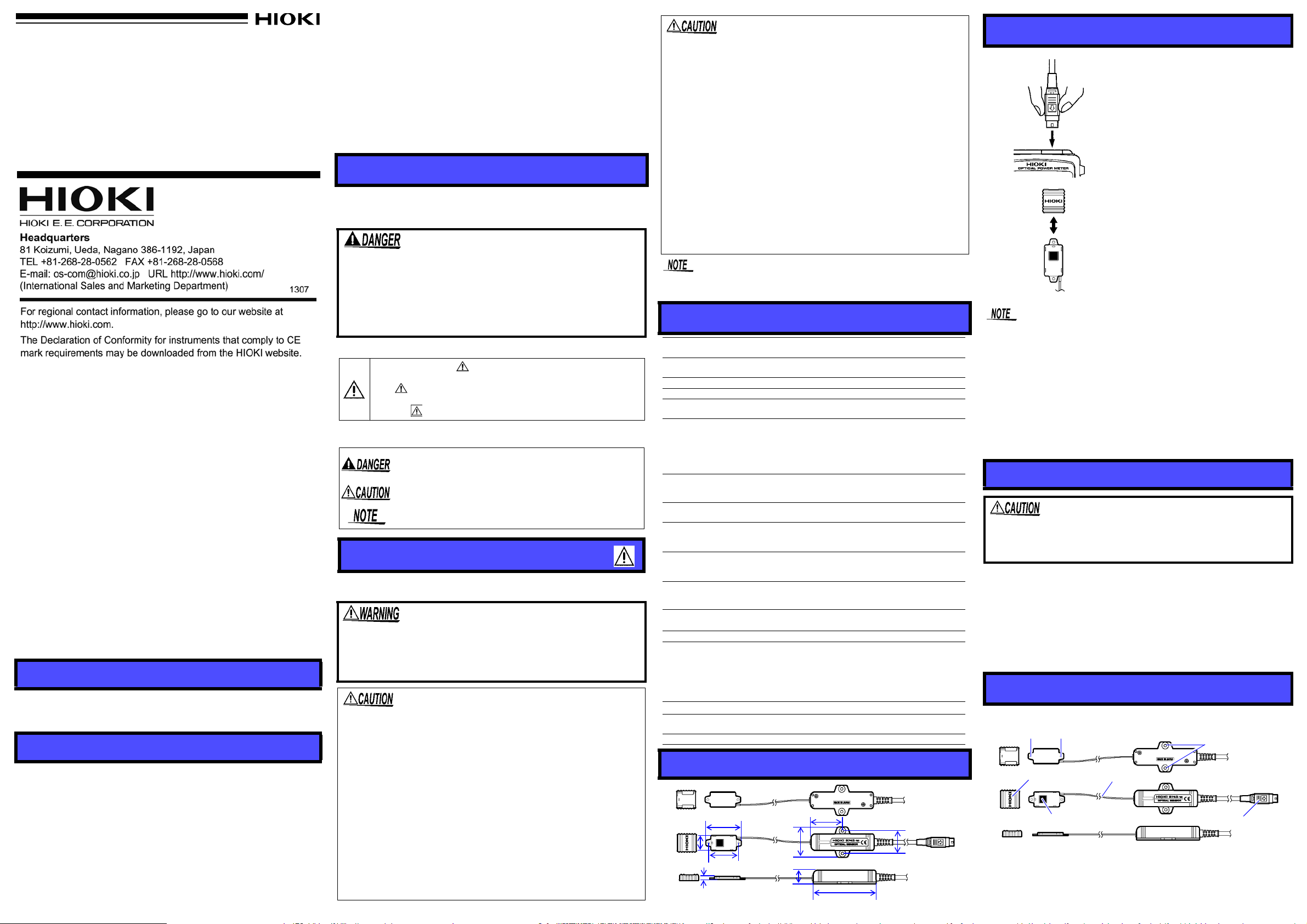
光センサ
OPTICAL SENSOR
取扱説明書 / Instruction Manual
2013 年 9 月 改訂 2 版 Printed in Japan
9743B980-02 13-09H
9743-10
安全について
受光面
センサコネクタ
センサカバー
中継ケーブル
受光部取付けネジ穴(φ2.7)
本体部取付けネジ穴
(φ3.5)
1. 3664 本体の電源が OFFになっているこ
とを確認します。
2. 9743-10 光センサコネクタの矢印がある
面を上にして 3664 の光センサ接続端子
に差し込みます。
3. 3664 本体の電源を ON にします。
3664 画面に Err1 が表示される場合は
3664 が本器に対応していません。
「はじめに」を参照し、3664 にセンサ
データを設定してください。
4. 光センサのセンサカバーをとりはずし
ます。
5. 光を入射します。
84 mm
4.3 mm
18 mm
40 mm
20 mm
47 mm
42 mm
40 mm
30 mm
本器を安全にご使用いただくために、また機能を十二分に活用いただくため
に、下記の注意事項をお守りください。
使用前の確認
• 使用前には、保存や輸送による故障がないか、点検と動作確認をしてから使
用してください。故障を確認した場合は、お買上店 ( 代理店 )か最寄りの営
業所にご連絡ください。
• ケーブルの被覆が破れたり、金属が露出していないか、使用する前に確認し
てください。損傷がある場合は、お買上店 ( 代理店 ) か最寄りの営業所にご
連絡ください。
測定方法
この機器は IEC 61010 安全規格に従って、設計され、試験し、安全
な状態で出荷されています。測定方法を間違えると人身事故や機器
の故障につながる可能性があります。取扱説明書を熟読し、十分に
内容を理解してから操作してください。万一事故があっても、弊社
製品が原因である場合以外は責任を負いかねます。
安全記号
使用者は、取扱説明書内の マ-クのあるところは、必ず読み
注意する必要があることを示します。
使用者は、機器上に表示されている
て、取扱説明書の
してください。
取扱説明書の注意事項には、重要度に応じて以下の表記がされています。
操作や取扱いを誤ると、使用者が死亡または重傷につながる危険性が
極めて高いことを意味します。
操作や取扱いを誤ると、使用者が死亡または重傷につながる可能性が
あることを意味します。
操作や取扱いを誤ると、使用者が傷害を負う場合、または機器を損傷
する可能性があることを意味します。
製品性能および操作上でのアドバイス的なことを意味します。
使用上の注意
この取扱説明書には本器を安全に操作し、安全な状態に保つのに要する情報や
注意事項が記載されています。本器を使用する前に下記の安全に関する事項を
よくお読みください。
マ-クの該当箇所を参照し、機器の操作を
マ-クのところについ
センサの受光面は照射されたレーザ光を反射します。反射光も場合に
よっては目に危険なレベルになり、視力障害や失明にいたる場合があ
りますので十分注意してください。
仕様
測定波長
測定パワー
最大定格
受光素子
受光サイズ
測定確度
波長設定初期値
3664
光パワーメー
(
タ)
アナログ出力(
光パワーメータ)
使用温湿度範囲
保存温湿度範囲
確度保証温湿度範囲
確度保証期間
使用場所
外形寸法
質量 約
適合規格 安全性 :
付属品 取扱説明書
380~450 nm
校正波長にて
100 mW (+20 dBm)
Si
フォトダイオード
約
10 mm×10 mm
4.3
%
±
校正条件:校正波長
基準波長)、校正パワー
ビームをセンサ中心に垂直入射、
との組み合わせにおいては±
400 nm, 403 nm, 405 nm, 408 nm
3664
にて波長設定メモリの初期値として上記が設定さ
れる(変更不可)
3664
約
0.7 V
0~40℃, 80%rh
-10~50℃, 80%rh
23±5 ℃, 80%rh
1
年間
高度
2000
受光部:約
本体部:約
受光部ー本体部間ケーブル長:約
ケーブル長:約
100 g
EMC
-50 dBm~+20 dBm
全面照射にて
405 nm(405 nm±5 nm
100 μW
(測定確度の校正条件入力において)
以下(結露なきこと)
以下(結露なきこと)
以下
m 以下、屋内
20W×47H×4.3D mm
(ケーブル部、カバー含まず)
40W×84H×18D mm
(ケーブル部、突起物含まず)
2000 mm
EN61010
:
EN61326
汚染度
2
5 %
、約 φ
3664
光パワーメータ
160 mm
1.5mm
内の弊社
の平行
• 光センサの脱着時は、必ず矢印があるコネクタ部を持って引き抜いてくださ
い。コネクタ部以外を持って引っ張っても、取り外すことができません。
• 受光面の汚れ、損傷を防ぐため、測定しないときは受光面にセンサカバーを
してください。
• とりはずしたセンサカバーを紛失しないようご注意ください。
• センサカバーの取付けには方向性があります。HIOKI のロゴが図の向きにな
るようにセンサカバーを装着してください。
受光面のクリーニング
はじめに
このたびは、HIOKI 9743-10 光センサ をご選定いただき、誠にありがとうご
ざいます。この製品を十分にご活用いただき、末長くご使用いただくために
も、取扱説明書はていねいに扱い、いつも手元に置いてご使用ください。
本器をはじめてお使いになる際には 3664光パワーメータ のソフトウェアバー
ジョンをご確認ください。
3664 のソフトウェアバージョンは 3664 電源投入時に画面において「3664」の
下に表示されます。バージョン 1.02 以降の 3664 では本器をそのままお使いい
ただけます。バージョン 1.01 以前で本器に未対応の 3664 に接続した場合、
3664の画面に Err1が表示され測定することができません。3664の画面に Err1
が表示された場合は弊社 web サイト (http://www.hioki.co.jp) より 3664 用の
センサデータ設定ソフトウェア(Hioki 3664 Setup Utility)をダウンロード
し、3664 をセットアップしてください。3664 のセンサデータ設定の詳細はダ
ウンロードファイルに添付されている資料をご覧ください。
概要
9743-10 光センサは、3664 光パワーメータ用の光センサです。測定波長 380
~ 450 nm、最大 100 mW まで測定可能です。
点検
本器がお手元に届きましたら、輸送中において異常または破損がないか点検し
てからご使用ください。万一、破損あるいは仕様どおり動作しない場合は、お
買上店 ( 代理店 ) か最寄りの営業所にご連絡ください。
• 3664の電源が ON の状態で、光センサコネクタの抜差しをしない
でください。3664 本体および光センサの故障の原因になります。
• 光センサの損傷を防ぐため、正確に測定するため、光センサを落
下させたり衝撃を加えないでください。
• 受光面には直接手で触れないでください。受光面が汚れると、性
能を満足しなくなる恐れがあります。
• 受光面は、鋭利なもの(ピンセットの先など)や硬い平面との摩
擦は避けてください。受光面を傷つけると、性能を満足しなくな
る恐れがあります。
• 断線による故障を防ぐため、ケーブルを折ったり引っ張ったりし
ないでください。
• 断線防止のため、光センサコネクタを引き抜くときは、差込部分
(ケーブル以外)を持って抜いてください。
• 極度に集光されたビームを測定する場合は、センサ上の光パワー
密度が過大になり、正確な測定ができないことがあります。また、
センサが劣化する原因になります。センサの感度変化を防ぐため
に、入射パワーが 50 mW 以下の場合は、光パワー密度が 10 mW/
2
以下の条件で使用してください。
mm
• 入射パワーが 50 mW を超える場合は、センサの受光面上のビー
ムサイズが極力大きくなる位置にセンサを設置してください。全
面照射であれば 100 mW の入射が可能です。
• センサ受光部、センサ本体間の中継ケーブルにはストレスがかか
らないようにしてください。
• 本器は防じん・防水構造となっていません。ほこりの多い環境や
水のかかる環境下で使用しないでください。故障の原因になりま
す。
• この機器は室内用に設計されています。安全性を損なわないで 0
℃~ 40 ℃の温度まで使用できます。
正確な測定を行うため、受光面にゴミ、ほこり、汚れが付着しないようにして
ください。また、傷がつかないようにしてください。
各部の名称
取付けネジ穴を使って9743-10の受光部と本体部をネジで固定することができ
ます。
保守・サービス
• 本器の汚れをとるときは、柔らかい布に水か中性洗剤を少量含ませて、軽く
拭いてください。ベンジン、アルコ-ル、アセトン、エ-テル、ケトン、シ
ンナ-、ガソリン系を含む洗剤は絶対に使用しないでください。変形変色す
ることがあります。
• 受光面のクリーニングには、エチルアルコール以外の有機溶剤は使用しない
でください。受光面の劣化の原因となる恐れがあります。
• 故障と思われるときは、
い。輸送中に破損しないように梱包し、故障内容も書き添えてください。輸
送中の破損については保証しかねます。
• 本器の確度維持あるいは確認には、定期的な校正が必要です。
お買上店(代理店)
か最寄りの営業所にご連絡くださ
エチルアルコール以外の有機溶剤は使用しないでください。受光面
の劣化の原因となる恐れがあります。
1. センサカバーをとりはずします。
2. 受光センサ部の受光面をレンズクリーニングペーパのようなほこりの出に
くいもので軽く拭きます。
受光面に繊維が残っている場合は、光学レンズ用エアブラシなどで吹き飛
ばします。
また、汚れがある場合は、綿をほぐして筆のようにした綿棒を用いて、エ
チルアルコールをしみ込ませた状態で軽く拭き取ってください。
外形寸法図
Warranty
Maintenance and Service
9743-10
OPTICAL SENSOR
Instruction Manual
September 2013 Revised edit ion 2 Printed in Japan
9743B980-02 13-09H
84 mm
4.3 mm
18 mm
40 mm
20 mm
47 mm(1.85”)
42 mm(1.65”)
40 mm
30 mm(1.18”)
(0.79”)
(1.57”)
(3.31”)
(0.17”)
(0.71”)
(1.57”)
1. Make sur e power for the 3664
is OFF.
2. Place the 9743-10 optical sensor with the arrow side facing
up and insert into the optical
sensor connector of the 3664.
3. Turn on power for the 3664.
If the 3664 display shows
"Err1", then the 3664 is not
compatible with this device.
Refer to "Introduction",
and
set up your 3664
.
4. Remove the cover of the optical sensor.
5. Irradiate with light.
Detector window
Sensor connector
Sensor cover
Repeater cable
Detector
mounting screw holes
(3.5 mm dia)
mounting screw holes (2.7 mm dia)
Main unit
Warranty mal functions occurring under co nditions of normal use in conformity with the Instruction Manual and Product Precautionary Markings will be repaired free of charge. This warranty is valid for a period
of one (1) year from the da te of purc ha se . Ple as e co nt act the distributor from which you purchased the product for further information on
warranty provisions.
Introduction
Thank you for purchasing the HIOKI Model 9743 -10 OPTICAL
SENSOR. To obtain maximum performance from the device,
please read this manual first, and keep it handy for future reference.
Upon first use of th e 9743-10 , please c onfirm the software
version of your 3664 OPTICAL POWER METER.
The 3664 software version is shown under the "3664" on the display screen at power up. If the 3664 is Version 1.02 or later, the
9743-10 can be used immediately. If the 9743-10 is connected to
a 3664 that is Version 1.01 or earlier, "Err1" will be displayed on
the 3664 screen and measurement will not be possible. If "Err1"
appears on the 3664 display screen, please download the 3664
Sensor Data Setup Software (Hioki 3664 Setup Utility) from our
website (http://www.hioki.co.jp) and set up your 3664. For detailed instructio ns on h ow to perform the se nsor dat a s etup of th e
3664, see the document included with the downloaded files.
Overview
The 9743-10 is an optical sensor for the 3664 OPTICAL POWER
METER capable o f measuring up to 100 mW in the range of wa velengths from 380 to 450 nm.
Inspection and Maintenance
Initial Inspection
When you receive the d evice, inspect it carefully to en sure that no damage occurred during sh ippin g. If dama ge is evide nt, or if it fails to operate according to the specifications, contact your dealer or Hioki
representative.
Preliminary Checks
• Before usi ng the d evi ce the f irst tim e, v eri fy th at i t operates normally
to ensure that the no dama ge occurred durin g storag e or shipp ing. If
you find any damage, contact your dealer or Hioki representative.
• Before usin g the devi ce , mak e su re tha t the ins ul ation on the cables
is undamaged and that no bare conductors are improperly ex po se d.
Using the device in such conditions could cause an electric shoc k,
so contact your dealer or H ioki representative for repair.
• To clean the device, wipe it gently with a soft cloth moistened with
water or mild detergent. Never use solvents such as benzene, alcohol, acetone, ether, ketones, thinners or gasoline, as they can
deform and discolor the case.
• With the exception of ethyl alcohol, avoid using organic solvents to
clean the detector window. These solve nt s c an dam ag e the detector
window.
• If the device seems to be malfunctioning, contact your dealer or
Hioki representative.
• Pack the device so that it will not sustain damage during shipping,
and include a description of existing damage. We cannot accept
responsibility for damage incurred during shipping.
Safety Information
This manual cont ains informa tion and warnings essential for s afe operation of the devi ce and for mai ntaining it i n safe operating condition. Before using it, be sure to carefu lly re ad the followi ng sa fety pre cauti ons.
This device is designed to comply with IEC 61010 Safety
Standards, and has been thoroughly te sted f or safety prior to
shipment. However, mishandling during use could result in
injury or death, as well as damage to the device. B e certain
that you understand the instructions and precaution s in the
manual before use. We disclaim any resp onsibility for accidents or injuries not resulting directly from device defects.
Safety Symbol
In the manual, the symbol indicates particularly important
information that the user should read before using the device.
The symbol printed on the device indicates that the user
should refer to a corresponding topic in the manual (marked
with the symbol) before using the relevant function.
The following symbols in this manual indicate the relative importance
of cautions and warnings.
Indicates that incorrect operation presents an extreme
hazard that could result in serious injury or death to the
user.
Indicates that incorrect operation presents a possibility
of injury to the user or damage to the device.
Indicates advisory items related to performance or correct operation of the
device.
Operating Precautions
Follow these prec autions to ensu re safe o peratio n and to obtai n the fu ll
benefits of the various functions.
The sensor detector window reflects irradiated laser
light. Under certain circumstances even this reflected
light can reach levels dangerous to the eye, potentially causing blurring or loss of vi sion, so pl ease use
sufficient caution when handling.
• To prevent m alfunctions in the 3664 or the optical sensor,
avoid connecting or disconnecting the optical sensor connector while power for the 3664 is ON.
• T o avoid damaging the optical sensor and to ensure accurate
measurements, avoid dropping or applying any physical
shock to the optical sensor.
• Avoid touching the detect or window with your bare hands.
The detector window mu st be clean for the sensor to meet
the specified performance parameters.
• Avoid scratching the detecto r window with sha rp or pointed
objects (e.g., the tips of tw eezers) o r aga inst h ard sur faces.
Damage to the detector window may prevent the sensor
from meeting specified performance parameters.
• To avoid breaking the cables, do not bend or pull them.
• To avoid broken wi res, alway s grasp the plug to discon nect
the optical sensor connector. Avoid pulling on the cable itself.
• When measuring an extremely concentrated beam the optical power density on the sensor may become excessive and
accurate measurement may not be possible. This may also
cause the sensor to wear out. In order to avoid a loss of sensor sensitivity, use the 9743-10 under conditions where the
optical power den si ty i s 10 mW /mm
2
or less when the inci -
dent power is 50 mW or less.
• When the incident power is greater than 50 mW position the
sensor so that the beam size is as la rge as possib le on the
sensor detector window. Incident power of 10 0 mW is pos sible if the full area is irradiated.
• Make sure no stress is applied to the repeater cable between
the sensor main unit and its light-receiving element.
• This device is not designed to be entirely water- or dust-proof.
Do not use it in an especially dusty environment, nor where it
might be splashed with liquid. This may cause damage.
• This device is designe d for use indoors. It ca n be operated
at temperatures between 0 and 40°C (32 and 104°F)
without
degrading safety.
To ensure accurate measurements, make sure the detector window is
free of dust, stains, and any damage.
Specific ations
Measurement
wavelength
Acceptable
power range
Maximum rating 100 mW (+20 dBm) with total irradiation
Detector type Si photodiode
Dimensions of light-
receiving area
Measurement
accuracy
Default wavelength
settings
(Model 3664)
Analog output
(Model 3664)
Operating temperature and humidity
ranges
Storage temperature and humidity
ranges
Accuracy guarantee
for temperature and
humidity
Guaranteed accuracy period
Location for use Indoors, altitude up to 2000 m (6562-ft.)
Dimensions
Mass
Applicable
Standards
Accessory Instruction manual
380 to 450 nm
-50 dBm to +20 dBm at the calibration wavelength
Approx. 10 mm x 10 mm
±4.3%
Calibration conditions: Direct a 100 μW collimated He-Ne
laser beam (approx. 1.5 mm dia) with a wavelength of
633 nm perpendicularly into the center of the sensor.
(Our standard wavelength: 405 nm ±5 nm)
Accuracy is ±5% when the sensor is used with the 3664.
400 nm, 403 nm, 405 nm, 408 nm
These are the default wavelengths stored in memory by
the 3664. They cannot be edited.
Approx. 0.7 V (when measurement precision calibration
conditions are input )
0 to 40°C (32 to 104°F),
80% RH or less (no condensation)
-10 to 50°C (14 to 122°F),
80% RH or less (no condensation)
23 ± 5°C (73 ± 9°F), 80% RH or less
1 year
Light-receiving element : Approx. 20W x 47H x 4.3D mm
(0.79”W x 1.85”H x 0.17”D) (excluding Sensor cover)
Main unit : Approx. 40W x 84H x 18D mm
(1.57”W x 3.31”H x 0.71”D) (excluding projections)
Repeater cable lengths : Approx. 160 mm (6.30”)
Cable lengths : Approx. 2000 mm (78.74”)
Approx. 100 g (3.5 oz.)
Safety :EN61010 Pollution degree 2
EMC :EN61326
Dimensional Diagram
Measurement Procedure
• Always grasp the conne ctor wi th the arr ow to co nnect or di sconnect the optical sensor. You mus t grasp the connecto r to
disconnect the sensor.
• To prevent dust accumulation, stains, and damage, cover the
detector window with the sensor cover when the sensor is
not in use.
• Take care to avoid misplacing the sensor cover.
• Note the correct orientation of the se nsor cover. The HIOKI
logo should face in the direction indicated in the diagram
above.
Cleaning the detector window
With the exception of ethyl alcohol, avoid using organic so lvents to clean the detector windo w. These solvents can damage the detector window.
1.Open the sensor cover.
2.Wipe the de tector window of the se nsor using lens cleani ng
paper or other lint-free material.
If lint remains on the detector window, blow off with an optical
lens airbrush.
If the detector window is soiled, flu ff the tip of a cotton swab.
Moisten the cotton tip in ethyl alcohol and wipe the surface.
Names of Parts
The 9743-10 sensor main unit and its detector may be attached
with screws. (Note the mounting screw holes.)
 Loading...