

Hioki 9675 Instruction Manual
Warranty
9675
CLAMP ON LEAK SENSOR
Instruction Manual
July 2015 Revised edition 8
Printed in Japan
9675A981-08 15-07H
Warranty malfunctions occurring under conditions of normal
use in conformity with the Instruction Manual and Product Precautionary Markings will be repaired free of charge. This warranty is valid for a period of one (1) year from the date of
purchase. Please contact the distributor from which you purchased the product for further information on warranty provisions.
Introduction
Thank you for purchasing the HIOKI Model 9675 CLAMP ON
LEAK SENSOR. To obtain maximum performance from the
product, please read this manual first, and keep it handy for future reference.
Inspection and Maintenance
Initial Inspection
When you receive the product, inspect it carefully to ensure that
no damage occurred during shipping. If damage is e vident, o r if
it fails to operate according to the specifications, contact your
dealer or Hioki representative.
Maintenance and Service
• To clean the product, wipe it gently with a soft cloth moistened with water or mild detergent. Never use solvents such
as benzene, alcohol, acetone, ether, ketones, thinners or
gasoline, as they can deform and discolor the case.
• If the product seems to be malfunctioning, contact your
dealer or Hioki representative. Pack the product so that it will
not sustain damage during shipping, and include a description of existing damage. We cannot accept responsibility for
damage incurred during shipping.
• Use the original packing materials when transporting the
product, if possible.
Safety
This manual contains information and warnings essential for
safe operation of the product and for mainta ining it in safe o perating condition. Before using it, be sure to carefu lly read the fo llowing safety precautions.
This product is designed to comply with IEC 61010
Safety Standards, and has been thoroughly tested for
safety prior to shipment. However, mishandling during
use could result in injury or death, as well as damage to
the product. Be certain that you understand the instructions and precautions in the manual before use. We disclaim any responsibility for accidents or injuries not
resulting directly from product defects.
Safety Symbol
Indicates cautions and hazards. When the symbol is
printed on the product, refer to a corresponding topic in the
Instruction Manual.
Indicates AC (Alternating Current).
Indicates that only insulated conductors suited to the volt-
age of the circuit under test can be measured.
Symbols for various standards
This symbol indicates that the product conforms to regulations set out by the EC Directive.
Indicates the Waste Electrical and Electronic Equipment
Directive (WEEE Directive) in EU member states.
Usage Notes
Follow these precautions to ensure safe operation and to obtain
the full benefits of the various functions.
• Do not measure around a bare conductor. Doing so
may result in short-circuit or electric shock. Take measurements at a location on an insulated wire where
there is sufficient insulation for the circuit voltage.
• This product should only be connected to the secondary side of a breaker, so the breaker can prevent an
accident if a short circuit occurs. Connections should
never be made to the primary side of a breaker,
because unrestricted current flow could cause a serious accident if a short circuit occurs.
• When the clamp sensor is opened, do not allow the
metal part of the clamp to touch any exposed metal, or
to short between two lines.
• To avoid electric shock, do not allow the product to get
wet, and do not use it when your hands are wet.
• To avoid electric shock when measuring live lines,
wear appropriate protective gear, such as insulated
rubber gloves, boots and a safety helmet.
• To avoid electric shock when measuring the ground
conductor on an E (PE) transformer connection site,
be careful not to approach high voltage devices or
conductors. Also, if close to high voltage charging
devices or if measurement is otherwise difficult, first
change the route of the grounding wire.
• Do not use the product where it may be exposed to
corrosive or combustible gases. The product may be
damaged or cause an explosion.
• Do not store or use the product where it could be exposed to
direct sunlight, high temperature or humidity, or condensation. Under such conditions, the product may be damaged
and insulation may deteriorate so that it no longer meets
specifications.
• To avoid damage to the product, protect it from vibration or
shock during transport and handling, a nd be especially careful to avoid dropping.
• Be careful to avoid dropping the product or otherwise subjecting them to mechanical shock, which could damage the
mating surfaces of the core and adversely affect measurement.
• Keep the clamp jaws and core slits free from foreign objects,
which could interfere with clamping action.
• Keep the clamp closed when not in use, to avoid accumulating dust or dirt on the mating core surfaces, which could interfere with clamp performance.
• Measurements are degraded by dirt on the mating surfaces
of the clamp-on sensor , so keep the surfaces clean by g ently
wiping with a soft cloth.
• This product is not designed to be entirely water- or dustproof. To avoid damage, do not use it in a wet or dusty environment.
• This product is designed for indoor use, and operates reliably from 0°C to 50°C.
• This product should be installed an d operated in doors only,
between 0°C and 50°C and 80% RH or less
• Avoid stepping on or pinching the cable, which could damage the cable insulation.
• Keep the cables well away from heat sources, as bare conductors could be exposed if the insulation melts.
• To avoid damaging the sensor cable, do not bend or pull the
cable.
• Note that the product may be damaged if current exceeding
the selected measurement range is applied for a long time.
Correct measurement may be impossible in the presence of
strong magnetic fields, such as near transformers and high-current conductors, or in the presence of strong electromagnetic
fields such as near radio transmitters.
Overview
The Model 9675 CLAMP ON LEAK SENSOR provides voltage
output corresponding to sensed currents up to 10A AC. The
high-permeability magnetic material of the sensor’s core and
magnetic shield enables high-precision measurement of very
weak currents.
The following symbols in this manual indicate the relative
importance of cautions and warnings.
Indicates that incorrect operation presents an extreme
hazard that could result in serious injury or death to the
user.
Indicates that incorrect operation presents a significant
hazard that could result in serious injury or death to the
user.
Indicates that incorrect operation presents a possibility
of injury to the user or damage to the device.
Advisory items related to performance or correct operation of the product.
Specifications
Jaws
Cable
BNC connector
To remove the BNC connector,turn the connector counterclockwise and pull it out.
1. Engage the BNC connec-
tor grooves with the connectorguide projections,
and turn the connector
clockwise to lock the components.
2. Clockwise to lock the
components.
Lock
Connect the BNC connector.
Connector
Guide
BNC connector
grooves
1
2
Load Current Measurement
1. Open the jaws. Orient the
current direction indicator
to the load side and
clamp one conductor at
the center of the clamp.
2. Confirm that the jaws is
fully closed.
Position the clamp with the current direction indicator pointing
toward the load side. (If installed
in the opposite direction,the
phase deviates 180 degrees.)
L
O
A
D
S
O
U
RC
E
Clamp the conductor.
Current direction
indicator
Conductor
OK
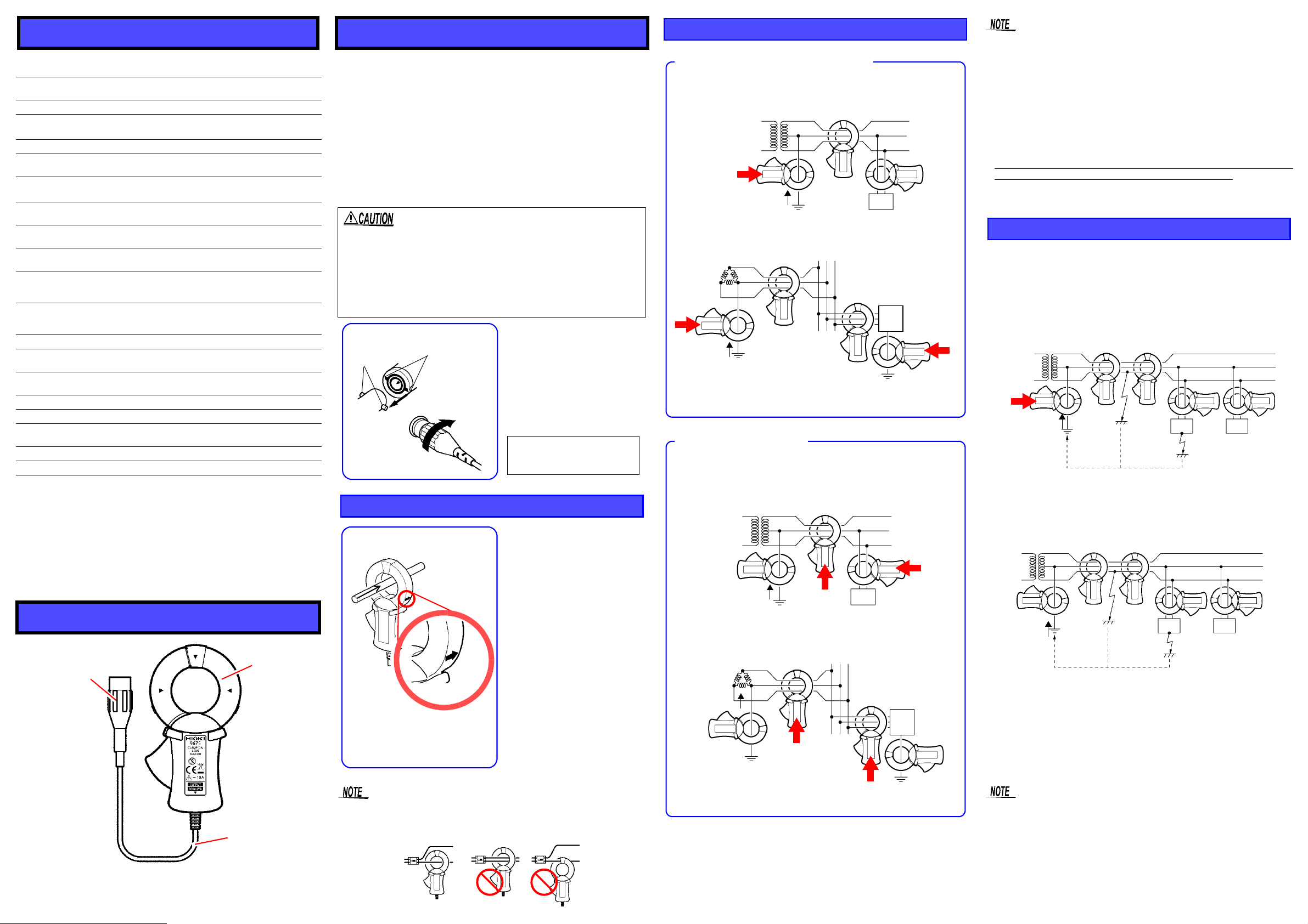
Leak Current Measurement
lg
Attach the clamp around only one conductor.
Ground Conductor Measurement
Single-phase 3-lead circuits
Three-phase 3-lead circuits
Transformer
Load
Device
Load
Device
Leak Current
Clamp
here
Clamp
here
Clamp
here
PE
E (PE)
lg
Leak Current
E (PE)
負荷
機器
Circuit conductors are bundled and clamped in the middle.
See ”Load Current Measurement”.
Bundle Measurement
Load
Device
Load
Device
Transformer
PE
E (PE)
lg
Leak Current
Clamp all three leads
of the circuit.
Clamp all three leads
of the circuit.
Single-phase 3-lead circuits
Three-phase 3-lead circuits
Clamp
here
Clamp
here
Clamp
here
Clamp
here
E (PE)
lg
Leak Current
Checking for insulation faults
1. Measure overall circuit leakage current and determine leak-
age conditions based upon measurement discrepancies.
Normally measured on the ground line of an E (PE) transformer.
Single-phase 3-lead circuits
Load
Device
Load
Device
lg
Leak Current
Clamp
here
E (PE)
2. If current leakage is detected, further bundled measurements
(clamping around bundled conductors) is employed to search
from the source to the load side.
Location A
a
a'
b
b’
Load
Device
Load
Device
lg
Leak Current
E (PE)
of isolation
fault
Location B
of isolation
fault
Accuracy guaranteed for one year at 23 ± 5°C (73 ± 9°F), 80%RH or
less (Opening and Closing of the Sensor: Maximum 10000 times).
Rated primary
10 A AC
current
Output voltage 100 mV AC/A
Amplitude
accuracy
±
1.0% rdg. ± 0.005% f.s. (f.s.: 10 A at the clamp
core center, 45 Hz to 66 Hz)
Phase accuracy within ± 5° (at 50 Hz or 60 Hz)
Amplitude frequency
characteristics
Maximum
input current
Effect of
conductor position
Effect of external
magnetic fields
Remaining electric
current character
Operating
temperature and
humidity range
Storage
temperature and
Within ± 5% at 40 Hz to 5 kHz
(deviation from accuracy)
10 A continuous at 45 Hz to 66 Hz
(Ambient temperature: 50°C
)
within ± 0.1%
(deviation from center)
Max. 7.5 mA
(400 A AC/m corresponds)
1 mA or less (10 A AC, 50/60 Hz on forward and
return lines with 10 mm or less line spacing)
0°C to 50°C (32°F to 122°F)
80%RH or less (no condensation)
-10°C to 60°C (14°F to 140°F)
80%RH or less (no condensation)
humidity range
Location for use Altitude up to 2000 m (6562 feet), Indoors
Standards
applying
Diameter of
able conductor
measur-
(Safety) EN61010
(EMC) EN61326
30 mm (1.18") or less
Me as u r a b l e co n d u c t or Insulated conductor
Cable length Isolated BNC, Approx. 3 m (118.11")
External
dimensions
Approx. 60W x 112.5H x 23.6D mm (2.36"W x
4.43"H x 0.93"D, excluding protrusions)
Mass Approx. 160 g (5.6 oz.)
Accessories Instruction manual (1)
We define measurement tolerances in terms of f.s. (full scale)
and rdg.(reading) values, with the following meanings:
f.s.
(maximum display value or scale length)
The maximum displayable value or the full length of the scale.
This is usually the maximum value of the currently selected
range.
(reading or displayed value)
rdg.
The value currently being measured and indicated on the measuring product.
Parts Names
Measurement Procedure
Preliminary Checks
• Before using the product the first time, verify that it operates
normally to ensure that the no damage occurred during storage or shipping. If you find any damage, contact your dealer
or Hioki representative.
• Before using the product, make sure that the insulation on
the cables is undamaged and that no bare conductors are
improperly exposed. Using the product in such conditions
could cause an electric shock, so contact you r dealer or Hio ki
representative for repair.
Connecting the BNC Connector
• When disconnecting the BNC connector, be sure to release the lock before pulling off the connector . Forcibly
pulling the connector without releasing the lock, or pulling on the cable, can damage the connector.
• To prevent damage to the product and sensor, never
connect or disconnect a sensor while the power is on,
or while the sensor is clamped around a conductor.
• For measurement of single-phase 2-lead circuits, clamp both
leads of the circuit.
• For measurement of three-phase 4-lead circuits, clamp all
four leads of the circuit. If this is not possible, the measurement can also be carried out on the ground lead of the equipment.
• If a strong current (on the order of 100 A) is flowing in an adjacent circuit, accurate measurement may not be possible. Perform the measurement at a sufficient distance from other
current-carrying conductors.
• The frequency of special waveforms such as at the secondary
side of an inverter may not be indicated correctly.
• Do not input a current which exceeds the rated current.
Attach the clamp around only one conductor. Single-phase (2wire) or three-phase (3-wire) c ables clamped together will not
produce any reading.
• If an insulation fault in the wiring has occurred at position “A”
in the illustration, leak current will be detected at position “a”
using overall measurement, but not at position “a'”.
• If an insulation fault in the load equipment has occurred at
position “B” in the illustration, leak current will be detected at
position “b” using overall measurement, but not at position
“b'”.
For detection of intermittent leak current conditions (such as on ly
when a certain piece of equipment is operating), the use of a level recorder will be helpful.
 Loading...