

Page 1

Instruction Manual
For...は専用機種。複数の場合は「/」で区切る。不要の場合はとる。
3532-50
3522-50
LCR HiTESTER
形名を入力。 複数の場合は「/」で区切る。
9593-01
品名を入力。
RS-232C INTERFACE
December 2012 Revised edition 7 9593A983-07 12-12H
Page 2

Page 3

Contents
Introduction i
Chapter 1 Before Use 1
1.1 Check of External Appearance and Accessories 1
1.2 Shipping Precautions
1.3 Points for Attention During Use
1.4 Installing the RS-232C Interface
Chapter 2 Overview 5
2.1 Introduction to the 9593-01 RS-232C INTERFACE 5
2.2 Specifications
Chapter 3 Names of Parts 9
3.1 Controls and Connections 9
Chapter 4 Operation 11
4.1 Setting the RS-232C Communication Conditions 11
4.2 Communication Methods by the RS-232C
4.3 Message Format
4.3.1 Program Message 13
4.3.2 Response Messages 13
4.4 Headers 14
12
13
2
3
4
6
4.5 Data Formats
4.6 Delimiters
4.7 Separators
4.8 Abbreviation of Compound Commands
4.9 Output Queue
4.10 Input Buffer
4.11 Event Registers
15
16
16
17
18
18
19
Chapter 5 Command Reference 21
5.1 Command Summary 21
5.2 Format of Command Explanations
5.3 Particular Commands
5.5 Response Format for Queries as Numerical Value
5.6 Initialization Items
25
26
82
84
Page 4

Chapter 6 Sample Programs 85
Chapter 7 Troubleshooting 93
Index INDEX 1
Page 5
────────────────────────────────────────────────────
Introduction
Thank you for purchasing the HIOKI 9593-01 RS-232C INTERFACE for the
3532-50 and 3522-50 LCR HiTESTERs.
To obtain maximum performance from the product, please read this manual
first, and keep it handy for future reference.
This manual contains information and warnings essential for safe operation
of the product and for maintaining it in safe operating condition. Before
using the product, be sure to carefully read the following safety notes.
The following symbols in this manual indicate the relative importance of
cautions and warnings.
i
WARNING
CAUTION
NOTE
Indicates that incorrect operation presents a significant
hazard that could result in serious injury or death to
the user.
Indicates that incorrect operation presents a possibility
of injury to the user or damage to the product.
Advisory items related to performance or correct operation
of the product.
────────────────────────────────────────────────────
Page 6

ii
────────────────────────────────────────────────────
────────────────────────────────────────────────────
Page 7

1
────────────────────────────────────────────────────
Chapter 1
Before Use
1.1 Check of External Appearance and Accessories
When you receive the product, inspect it carefully to ensure that no damage
occurred during shipping.
In particular, check the accessories, panel switches, and connectors. If
damage is evident, or if it fails to operate according to the specifications,
contact your dealer or Hioki representative.
(1) 9593-01 RS-232C INTERFACE
(2) This instruction manual
────────────────────────────────────────────────────
1.1 Check of External Appearance and Accessories
Page 8
2
────────────────────────────────────────────────────
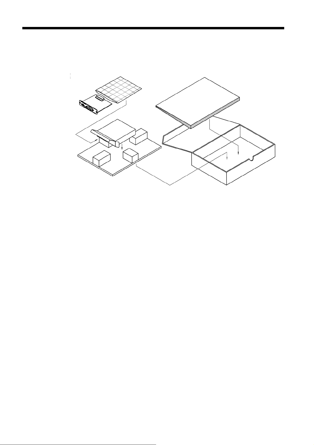
1.2 Shipping Precautions
If reshipping the unit, preferably use the original packing.
If this is not available, use the following procedure.
1. Wrap the unit in plastic sheeting.
2. After wrapping cushioning material around the unit, pack it into a
cardboard box, and then seal up the box with adhesive tape.
────────────────────────────────────────────────────
1.2 Shipping Precautions
Page 9

3
────────────────────────────────────────────────────
1.3 Points for Attention During Use
(1) If you change the communication condition of the 3532-50/3522-50 while
using it, you should immediately turn the power off and on again. If you do
not do so, the communication conditions will not be changed to the new one.
(2) Always be sure to secu
re the RS-232C cable to the 9593-01 unit by tightening up the fixing screws
provided.
(3) Program messages sent just after the power has been turned on are executed
after the self test has terminated.
(4) It is vital that the proper data format is used when inputting commands with
data values to the 3532-50/3522-50 units.
(5) For details of the various functions, refer to the instruction manuals for the
3532-50/3522-50 units.
────────────────────────────────────────────────────
1.3 Points for Attention During Use
Page 10
4
────────────────────────────────────────────────────
1.4 Installing the RS-232C Interface
WARNING
CAUTION
To avoid electric shock accident, before removing or replacing an
input module, confirm that the instrument is turned off and that the
power cord and connection cables are disconnected.
The mounting screws must be firmly tightened or the input unit may
not perform to specifications, or may even fail.
To avoid the danger of electric shock, never operate the product
with an input module removed. To use the product after removing
an input module, install a blank panel over the opening of the
removed module.
When inserting in the interface, hold the metal plate. Directly touching
the board may cause static electricity and lead to damage of the
instrument. (Using the wrist strap for preventing static electricity when
inserting is recommended.)
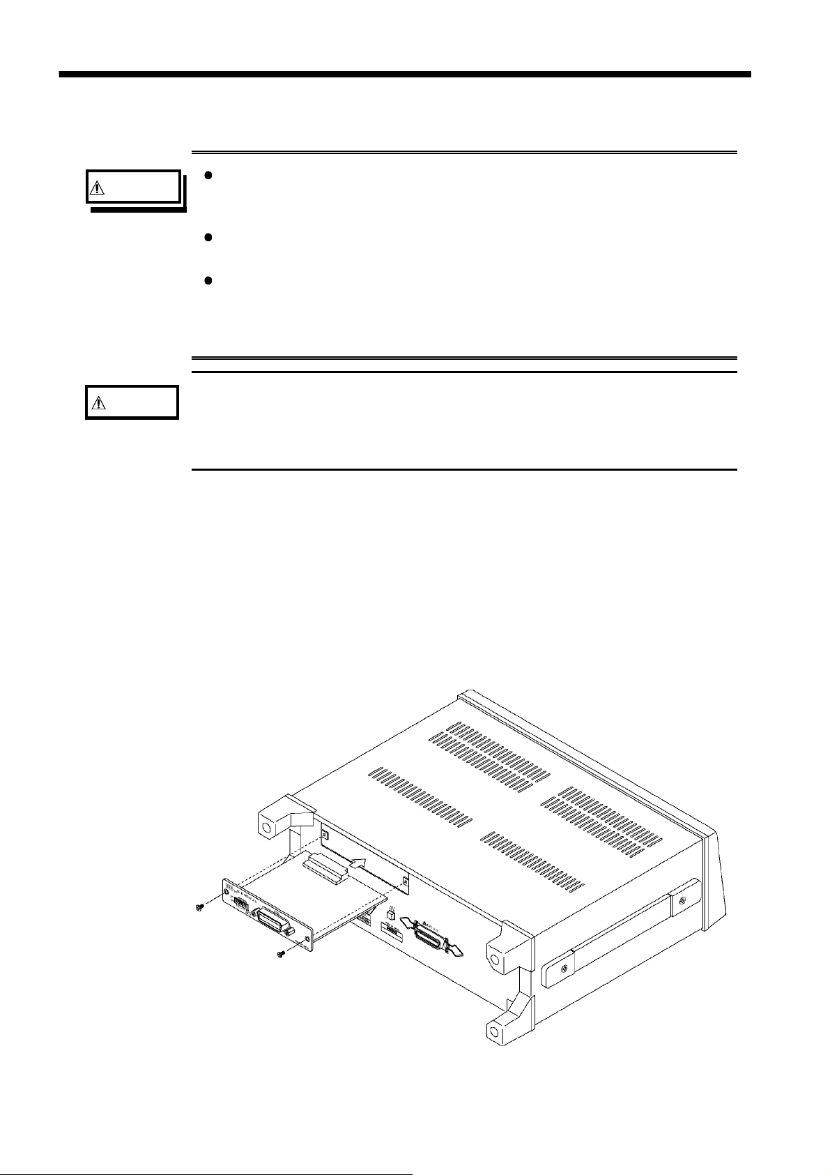
The space for fitting the 9593-01 RS-232C INTERFACE in the rear panel of
the 3532-50/3522-50 are covered with a blanking plate. Follow these three
steps to install the 9593-01 interface:
1. Remove the fixing screws, and take off the blanking plate.
2. Insert the 9593-01 RS-232C INTERFACE into the exposed slot in the rear
of the unit in the figure below.
3. Push the 9593-01 firmly into place, and fix with the screws removed in
step 1.
────────────────────────────────────────────────────
1.4 Installing the RS-232C Interface
Page 11

5
────────────────────────────────────────────────────
Chapter 2
Overview
2.1 Introduction to the 9593-01 RS-232C INTERFACE
By connecting the 9593-01 RS-232C INTERFACE to the 3532-50 or the
3522-50 LCR HiTESTER, it is possible to control the main unit via the RS232C bus.
────────────────────────────────────────────────────
2.1 Introduction to the 9593-01 RS-232C INTERFACE
Page 12
6
(
)
────────────────────────────────────────────────────
2.2 Specifications
Transfer system Start-stop synchronization
Baud rate 2400, 4800, 9600, 19200 bps
Data length 7or8bits
Parity Even, odd, or none
Stop bits 1or2bits
Delimiter CR+LF, CR
Handshake hardware
Selected by DIP switch.
Electrical characteristic
NOTE
Input voltage levels
Output voltage levels
(load impedance 3 kΩto 7 kΩ)
+5 V to +15 V
-15 V to -5 V
+5 V to +9 V
-9 V to -5 V
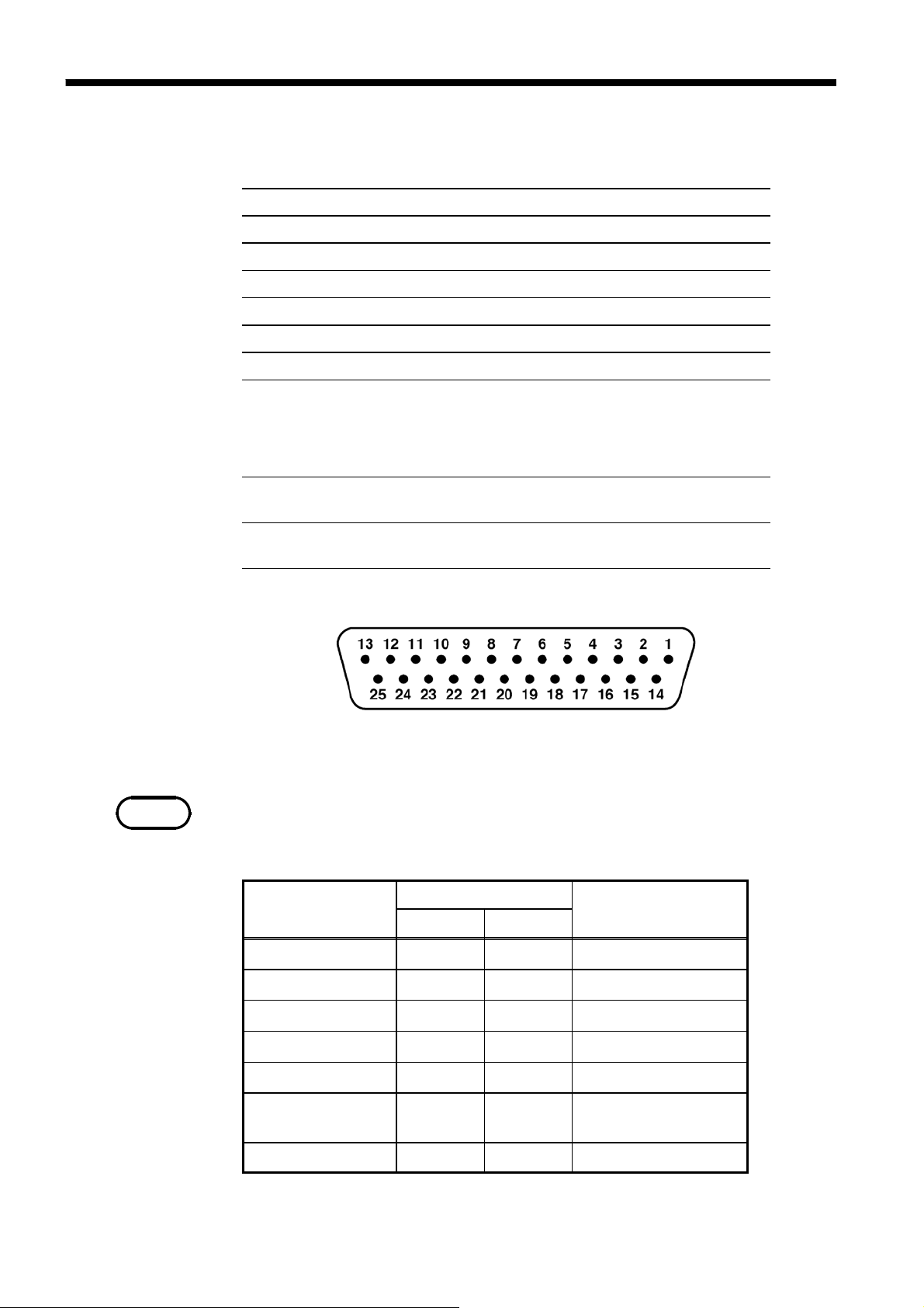
Connector
RS-232C Interface Connector Pin Assignments
D-subminiature 25-pin female
The connector on the 9593-01 is for terminal (DTE).
Signal Assignments and Explanation
Connector (Dsub)
Pin number
RS-232C CCITT
Circuit
ON
OFF
ON
OFF
Description
2 BA(TxD) 103
3 BB(RxD) 104
4 CA(RTS) 105
5 CB(CTS) 106
7 AB(GND) 102
20 CD(DTR) 108/2
Other pins
────────────────────────────────────────────────────
2.2 Specifications
Transmitted Data
Received Data
Request to Send
Clear to Send
Signal Ground
Data Terminal
Ready
Unused
Page 13

7
(
(
)
A
(
────────────────────────────────────────────────────
Connecting method
When connecting to the controller (DTE), use a cross cable which meets the
connector specifications of both sides of the 9593-01 and the controller.
When connecting to the PC/AT:
9593-01 PC/AT
BA (TxD) 2
BB (RxD) 3
CA (RTS) 4
CB (CTS) 5
CC (DSR) 6
AB (GND) 7
DTR) 20
CD
D-subminiature 25-pin
male
9593-01 PC/AT
BA (TxD) 2
BB (RxD) 3
CA (RTS) 4
CB (CTS) 5
CC (DSR) 6
B (GND) 7
CF (DCD) 8
DTR) 20
CD
2 BB (RxD)
3 BA (TxD)
8 CB (CTS)
7 CA (RTS)
4 CD (DTR)
5 AB (GND)
6 CC (RI)
D-subminiature 9-pin
female
2 BB (RxD)
3 BA (TxD)
1 CF (DCD)
4 CD (DTR)
5 AB (GND)
7 CA (RTS)
8 CB (CTS)
6 CC
DSR
D-subminiature 25-pin
male
D-subminiature 9-pin
female
────────────────────────────────────────────────────
2.2 Specifications
Page 14

8
pty
────────────────────────────────────────────────────
Handshake
(1) Controls when receiving
When the receiving buffer is more than 85% full, to indicate to the controller
that the empty buffer capacity is low (RTS is set to Low).
Processing of data in the buffer continues, and when the receiving buffer is
less than 25 % full, to indicate to the controller that there is ample buffer
capacity (RTS is set to Hi)
85%
Amount of input
buffer used
25%
Buffer em
RTS
Hi
Low
(2) Controls when transmitting
When CTS is Low, transmission is suspended; it is Hi transmission resumes.
────────────────────────────────────────────────────
2.2 Specifications
Page 15

9
────────────────────────────────────────────────────
Chapter 3
Names of Parts
3.1 Controls and Connections
(1) Initial Screens
During communications (in the remote state), the
remote state is displayed on the screen.
Press this key to resume the normal state (local state).
LOCAL
key to release the
During communications, the initial screen is forcibly displayed excluding the
following conditions.
・
When executing OPEN/SHORT correction or sending the execution
command (correction execution screen appears).
・
When the magnification display screen appears.
────────────────────────────────────────────────────
3.1 Controls and Connections
Page 16
10
r
────────────────────────────────────────────────────
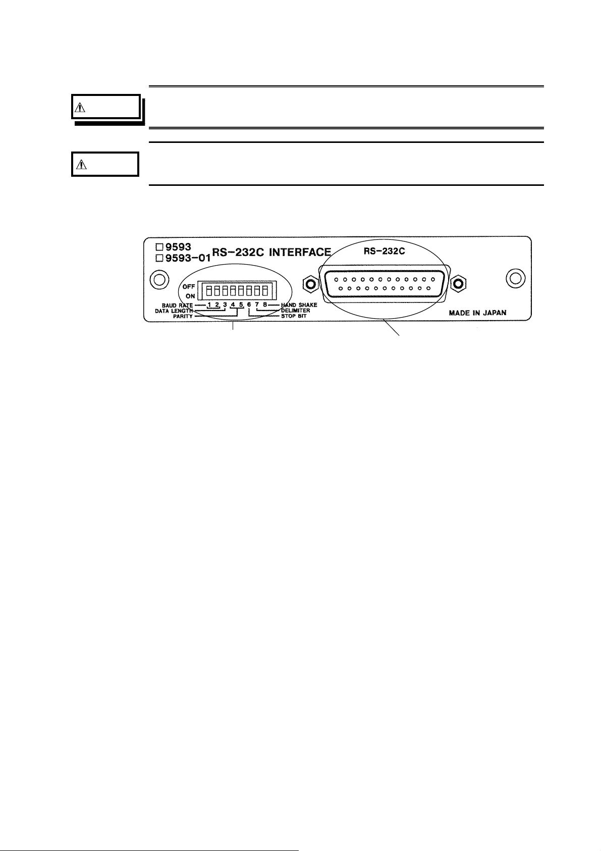
(2) 9593-01 RS-232C INTERFACE
WARNING
CAUTION
To avoid electrocution, turn off the power to all devices before
pluggingor unplugging any of the RS-232C INTERFACE connectors.
To avoid damage to the product, do not short-circuit the output
terminal and do not input voltage to the output terminal.
Commu ni cation condition settingswitches
RS-232C connecto
Communication condition setting switches
These are used to set the communication condition of the 3532-50/3522-50
units on the RS-232C bus. For how to set these switches, refer to Section
4.1, "Setting the RS-232C Communication Conditions."
RS-232C connector
Connect the RS-232C cable to this connector.
────────────────────────────────────────────────────
3.1 Controls and Connections
Page 17

11
────────────────────────────────────────────────────
Chapter 4
Operation
4.1 Setting the RS-232C Communication Conditions
・
Use the communication condition setting switches on the RS-232C panel to
set the communication condition.
NOTE
・
On dispatch from the factory, this address is initially set to 00000000.
If you change the communication condition while the 3532-50 or 3522-50
is being used, then you should immediately turn the power off and on
again.
If this is not done, the communication condition will not be changed to the
new one.
Bits Description
1
Baud rate
2
3 Data length
4
Parity
5
6 Stop bits
7 Delimiter
8 Handshake
0: OFF 1: ON
Bits Description
1 2 Baud rate
0 0
0 1
1 0
1 1
3 Data length
0
1
4 5 Parity
9600
4800
2400
19200
8bits
7bits
6 Stop bits
0
1
7 Delimiter
0
1
1bit
2bits
CR+LF
CR
0 0
0 1
1 0
1 1
None
None
Even
Odd
When using with the personal computer, set bit 8 to 0.
When using with the optional 9442 printer, set all bits to 1.
────────────────────────────────────────────────────
4.1 Setting the RS-232C Communication Conditions
Page 18

12
y
p
────────────────────────────────────────────────────
4.2 Communication Methods by the RS-232C
・
In order to control the 3532-50/3522-50 by the RS-232C, there are
several kinds of messages.
・
Of these, program messages are those received by the 3532-50/3522-
50 from the computer, while response messages are those sent from
the 3532-50/3522-50 to the computer.
Command messages
Messages
Program messages
Res
onse messages
Quer
(1) Program messages
Program messages are command messages or query messages.
・
Command messages are orders for controls of the 3532-50/3522-50,
such as for making measurement condition settings or for reset or the
like.
Example
FREQUENCY
(Command message which sets the frequency)
<data>
messages
・ Query messages are orders for responses relating to results of
operation, results of measurement, or the state of 3532-50/3522-50
settings. (A question mark "?" is suffixed at the end of the command.)
Example FREQUENCY?
(Queries the current frequency)
(2) Response messages
It represents the response data for query messages from the 3532-50/3522-
50.
Example
(Current frequency is 1 kHz.)
Computer
FREQUENCY 1.000E+03
Program messages
3532-50/3522-50
Response messages
────────────────────────────────────────────────────
4.2 Communication Methods by the RS-232C
Page 19

13
────────────────────────────────────────────────────
4.3 Message Format
The commands for the 3532-50/3522-50 are as far as possible mnemonic.
Furthermore, all commands have a long form, and an abbreviated short form.
4.3.1 Program Message
The program message is made up from header and data portions
Example
:
1
2 Space separating header portion and data portion.
3
Command message to set frequency to 1 kHz
FREQUENCY 1000
1 2 3
Header portion
Data portion (ASCII-format text or numeric values.
Some messages have no data portions...query messages, etc.)
A command header can be abbreviated. The whole command form is
referred to as the "long form" and the abbreviated form as the "short form."
In this manual, the short form is written in upper case letters, and then this
is continued in lower case letters so as to constitute the long form. Either of
these forms will be accepted during operation, but intermediate forms will
not be accepted. Further, during operation both lower case letters and upper
case letters will be accepted without distinction.
For "FREQUENCY", either "FREQuency" (the long form) or "FREQ" (the
short form) will be accepted. However, any one of "FREQU", or "FRE" is
wrong and will generate an error.
4.3.2 Response Messages
It represents the response message for query messages from the 353250/3522-50.
Response messages generated by the 3532-50/3522-50 are in long form and
in upper case letters.
Example
FREQUENCY 1.000E+03
(Current frequency is 1 kHz.)
NOTE
────────────────────────────────────────────────────
If an error occurs when the query message is received, the query does not
produce response message.
4.3 Message Format
Page 20

14
────────────────────────────────────────────────────
4.4 Headers
(1) Program message headers
There are three types of header: simple headers, compound headers, and
particular headers.
・Simpleheader
A header consisting of a single word beginning with a letter.
Examples
:HEADer
・ Compound header
A header consisting of a sequence of words separated by colons.
Examples
:BEEPer:KEY, RANGe:AUTO
・Particularheader
A header beginning with an asterisk (*) to indicate that it is a particular
command.
Examples
*
RST
, etc.
, etc.
, etc.
NOTE
(2) Response message
Headers in response messages can be enabled or disabled by using the
"HEADer" command.
Example
(Query message
Response message when headers are on.
1
2 Space separating header portion and data portion.
3
Response message when headers are off.
(Data portion only)
The headers are set to off when powering on.
When frequency is set to 1 kHz:
:FREQUENCY?
asking for the current setting of the frequency.
:FREQUENCY 1000
1 2 3
Header portion
Data portion
1000
)
────────────────────────────────────────────────────
4.4 Headers
Page 21

15
────────────────────────────────────────────────────
4.5 Data Formats
The 3532-50/3522-50 use character string data and decimal numeric data,
and the type used varies according to the command in question.
(1) Character data
Character string data must always begin with an alphabetic character, and
the characters following can be either alphabetic characters or numerals.
Although in character data either upper case letters or lower case letters are
accepted, response messages output by the 3532-50/3522-50 are always in
upper case letters.
Example
(2) Decimal data
:TRIGger INT
The numeric data values are all represented in decimal, in three formats
identified as NR1, NR2 and NR3, and each of these can appear as either a
signed number or an unsigned number. Unsigned numbers are taken as
positive.
Further, if the accuracy of a numerical value exceeds the limit which the
3532-50/3522-50 can deal, it is rounded off. (5 and above is rounded up; 4
and below is rounded down).
NR1 format - integer data.
Examples
+12, -23, 34
NR2 format - fixed point numbers.
Examples +1.23, -23.45, 3.456
NR3 format - floating point numbers.
Examples
+1E-2, -2.3E+4
The term "NRf format" includes all these three formats.
When the 3532-50 or 3522-50 is receiving it accepts NRf format, but when
it is sending response messages it utilizes whichever one of the formats NR1
to NR3 is indicated in the specified command.
Examples
:RANGe +6.012
:RANGe 0.0006E4
────────────────────────────────────────────────────
:RANGe 6
4.5 Data Formats
Page 22

16
────────────────────────────────────────────────────
4.6 Delimiters
The term "delimiter" is used to refer to the following possibilities for
separating data sequences.
The 3532-50 and 3522-50 recognizes either a carriage return (CR) or a
carriage return plus linefeed (CR+LF) as delimiters.
(1) CR (carriage return only)
(2) CR+LF (carriage return plus linefeed)
4.7 Separators
(1) Message unit separator
A semicolon (;) is used as a message unit separator when it is desired to set
out several messages on a single line.
Example
:RANGe:AUTO ON;:BEEP:KEY ON
; *
IDN?
NOTE
When messages are combined in this way, if a syntax error occurs, all
subsequent messages up to the next delimiter will be ignored.
(2) Header separator
In a message which has a header and data, a space (represented by " " in
the examples) is used as the header separator to separate the header from the
data.
Example
:LEVel V
(3) Data separator
If a message has several data items, commas (,) are required as data
separators for separating these data items from one another.
Example
:COMParator:FLIMit:ABSolute
<lower limit> ,<upper limit>
────────────────────────────────────────────────────
4.6 Delimiters
Page 23

17
────────────────────────────────────────────────────
4.8 Abbreviation of Compound Commands
When several compound headers have a common head portion (for example,
:BEEPer:KEY and :BEEPer:COMParator, etc.), then, when and only when
writing them directly following on from one another, this common portion
(:BEEPer: in this example) can be omitted.
This common portion is called "the current path", by analogy with the
general concept of the current directory in the directory structure of UNIX or
MSDOS, and until it is cleared the analysis of following commands is
performed by deeming them to be preceded by the current path which has
been curtailed in the interests of brevity. This manner of using the current
path is shown in the following example:
Normal expression
Abbreviated expression
:BEEPer:KEY ON;:BEEPer:COMParator NG
:BEEPer: KEY ON;COMParator NG
This becomes the current path, and can be
curtailed from the following commands.
The current path is cleared when the power is turned on, when a colon (:)
appears at the start of a command, and when delimiter is detected.
Messages with particular headers can be executed without relation to the
current path. Further, they have no effect upon the current path.
With the 3532-50/3522-50, there are 12 possible current paths:
:APPLication:DISPlay
:BEEPer:
:COMParator:FLIMit:
:COMParator:SLIMit:
:CORRection:
:LEVel:
:LIMiter:
:MEASure:
:RANGe:
:TRIGger:
:USER:
:SCALe:
────────────────────────────────────────────────────
4.8 Abbreviation of Compound Commands
Page 24

18
────────────────────────────────────────────────────
4.9 Output Queue
Response messages accumulate in the output queue and all data are received
and cleared.
The output queue is also cleared when the power is turned off and turned on
again.
The 3532-50/3522-50 have an output queue of 300 bytes capacity. If the
response messages overflow this limit of 300 bytes, a query error is
generated, and the output buffer is cleared
4.10 Input Buffer
The 3532-50/3522-50 have an input buffer of 300 bytes capacity.
When more than 300 bytes of data are transmitted, when the buffer is full
any subsequent bytes received will be ignored.
(When the controller handshake setting is not the same as the 9593-01.)
────────────────────────────────────────────────────
4.9 Output Queue
Page 25

19
────────────────────────────────────────────────────
4.11 Event Registers
The 3532-50/3522-50 include three 8-bit event registers. It is possible to
determine the
status of the unit by reading these registers.
The event register is cleared in the following situations:
・ Whena"*CLS" command is executed.
・ When an event register query is executed. (*
・ When the unit is powered on.
ESR?, :ESR0?, :ESR1?
(1) Standard event status register (SESR)
Standard Event Status Register (SESR) Bit Assignments
)
Bit 7
PON
Bit 6
Bit 5
CME
Bit 4
EXE
Bit 3
DDE
Bit 2
QYE
Bit 1
Bit 0
Power on flag.
When the power is turned on, or on recovery from a power cut,
this bit is set to 1.
Unused.
Command error.
When a command which has been received contains a syntactic or
semantic error, this bit is set to 1.
・ The command is not supported by the 3532-50/3522-50.
・ There is a mistake in a program header.
・ The number of data parameters is wrong.
・ The format of the parameters is wrong.
Execution error.
When for some reason a command which has been received
cannot be executed, this bit is set to 1.
・ The designated data value is outside the set r ange.
・ The designated data value is not acceptable.
・ Execution is impossible because some other function is being
performed.
Device dependent error.
When a command cannot be executed due to some cause other
than a command error, a query error, or an execution error, this
bit is set to 1.
・ Execution is impossible due to an abnormality inside the 3532 -
50/3522-50.
・ During open or short circuit compensation, valid data cannot be
obtained.
Query error.
This bit is set to 1 when a query error is detected by the output
queue control.
・ When the data overflows the output queue.
・ When data in the output queue has been lost.
Unused.
Unused.
────────────────────────────────────────────────────
4.11 Event Registers
Page 26
20
────────────────────────────────────────────────────
(2) Event status registers 0 and 1 (ESR0 and ESR1)
Event Status Register 0 (ESR0) Bit Assignments
Bit 7
Bit 6
COF
Bit 5
LOF
Bit 4
IOF
Bit 3
IUF
Bit 2
IDX
Bit 1
EOM
Bit 0
CEM
Unused
Constant current or constant voltage
Limit overflow
Impedance range overflow
Impedance range underflow
Data sampling completed
Measurement completed
Compensation data measurement completed
Event Status Register 1 (ESR1) Bit Assignments
Bit 7
Bit 6
AND
Bit 5
SLO
Bit 4
SIN
Bit 3
SHI
Bit 2
FLO
Bit 1
FIN
Bit 0
FHI
Unused
Logical product (AND) of comparison results (bit1, bit4)
Second parameter below lower limit
Second parameter within limits
Second parameter above upper limit
First parameter below lower limit
First parameter within limits
First parameter above upper limit
────────────────────────────────────────────────────
4.11 Event Registers
Page 27
21
────────────────────────────────────────────────────
Chapter 5
Command Reference
5.1 Command Summary
Particular Commands
Command Function
*CLS
*ESR?
*IDN?
*RST
*TRG
*TST?
*WAI
Clears event register.
Queries standard event status register (SESR).
Queries device ID.
Device initialization.
Performs sampling once.
Queries the result of the self-test.
Waits until all execution is fully completed.
Commands Specific to the 3532-50・3522-50
Command Function
■
Display function
:APPLication:DISPlay:LIGHt
:APPLication:DISPlay:LIGHt?
:APPLication:DISPlay:M ONItor
:APPLication:DISPlay:MONItor ?
Setting for LCD display.
Queries the setting for LCD display.
Setting for voltage and current monitors.
Queries the setting for voltage and current monitors.
Ref
page
26
26
27
28
29
29
30
Ref
page
31
31
32
32
■
Averaging function
:AVERaging
:AVERaging?
■
Beep sound function
:BEEPer:COMParator
:BEEPer:COMParator?
:BEEPer:KEY
:BEEPer:KEY?
────────────────────────────────────────────────────
Sets the number of measurement times for averaging.
Queries the number of measurement times for averaging.
Sets the beep sound for the comparator.
Queries the beep sound for the comparator.
Sets the beep sound for key input.
Queries the beep sound for key input.
5.1 Command Summary
33
33
34
34
35
35
Page 28
22
────────────────────────────────────────────────────
Command Function
■
External DC bias function
:BIAS
:BIAS?
■
Cable length setting function
:CABLe
:CABLe?
■
Comparator function
:COMParator
:COMParator?
:COMParator:FLIMit
:ABSolute
:ABSolute?
:DEViation
Enables and disables the external DC bias function.
Queries the external DC bias function enablement
Sets the cable length.
Queries the cable length.
Enables and disables the comparator function.
Queries the comparator function enablement.
(first parameter)
Sets the upper and lower limit values (absolute values).
Queries the upper and lower limit values (absolute values).
Sets the reference value and the upper and lower limit values
(deviation percentage values).
:DEViation? Queries the reference value and the upper and lower limit
values (deviation percentage values).
Ref
page
36
36
36
37
37
37
38
38
39
39
:MODE
:MODE?
:PERcent
Sets the first parameter setting mode.
Queries the first parameter setting mode.
Sets the reference value and the upper and lower limit values
(percentage values).
:PERcent?
Queries the reference value and the upper and lower limit
values (percentage values).
:COMParator:SLIMit
:ABSolute
:ABSolute?
(second parameter)
Sets the upper and lower limit values (absolute values).
Queries the upper and lower limit values (absolute values).
:DEViation Sets the reference value and the upper and lower limit values
(deviation percentage values).
:DEViation?
:MODE
:MODE?
:PERcent
:PERcent?
Queries the reference value and the upper and lower limit
values (deviation percentage values).
Sets the second parameter setting mode.
Queries the second parameter setting mode.
Sets the reference value and the upper and lower limit values
(percentage values).
Queries the reference value and the upper and lower limit
values (percentage values).
40
40
41
41
42
42
43
43
44
44
45
45
■
Open and short circuit compensation function
:CORRection:DATA?
:CORRection:OPEN
:CORRection:OPEN?
:CORRection:SHORt
:CORRection:SHORt?
────────────────────────────────────────────────────
5.1 Command Summary
Queries the open and short circuit compensation values.
Enables and disables the open circuit compensation function.
Queries the open circuit compensation function enablement.
Enables and disables the short circuit compensation
Queries the short circuit compensation function enablement.
46
47
48
49
50
Page 29

23
────────────────────────────────────────────────────
Command Function
■
Monitor function
:DISPlay:MONItor?
■
Communication error confirmation
:ERRor?
■
Event register
:ESR0?
:ESR1?
■
Test frequency function
:FREQuency
:FREQuency?
■
Headers
:HEADer
:HEADer?
■
EXT I/O Output
:IO:OUTPut:DELay
Queries the monitored voltage and current.
Queries the RS-232C error.
Queries event status register 0.
Queries event status register 1.
Sets the test frequency.
Queries the test frequency.
Enables and disables headers for the response message.
Queries headers enablement.
Sets the delay time for judgement result output EOM
output period in EXT I/O.
:IO:OUTPut:DELay?
Queries the delay time for judgement result output EOM
output period in EXT I/O.
:IO:RESult:RESet
Sets output of judgment result signal line in EXT I/O.
Ref
page
50
51
51
52
53
53
54
54
―――――
55
―――――
55
56
:IO:RESult:RESet?
■
Test signal level function
:LEVel
:LEVel?
:LEVel:CCURRent
:LEVel:CCURRent?
:LEVel:CVOLTage
:LEVel:CVOLTage?
:LEVel:VOLTage
:LEVel:VOLTage?
■
Limit function
:LIMiter
:LIMiter?
:LIMiter:CURRent
:LIMiter:CURRent?
:LIMiter:VOLTage
:LIMiter:VOLTage?
Queries output of judgment result signal line in EXT I/O.
Sets the test signal level.
Queries the test signal level.
Sets the constant current level value.
Queries the constant current level value.
Sets the constant voltage level value.
Queries the constant voltage level value.
Sets the open circuit voltage level value.
Queries the open circuit voltage level value.
Enables and disables the limit setting function.
Queries the limit setting function enablement.
Sets the current limit value.
Queries the current limit value.
Sets the voltage limit value.
Queries the voltage limit value.
56
55
55
56
56
57
57
58
58
59
59
60
60
61
61
■
Panel load function
:LOAD
────────────────────────────────────────────────────
Transfers the specified panel number.
5.1 Command Summary
62
Page 30

24
────────────────────────────────────────────────────
Command Function
■
Normal testings
:MEASure?
:MEASure:ITEM
:MEASure:ITEM?
■
Parameter settings (*:1 to 4)
:PARAmeter1
:PARAmeter1
(2, 3, or 4)
(2, 3, or 4)
:PARAmeter*:DIGit
:PARAmeter*:DIGit?
■
Test range function
:RANGe
:RANGe?
:RANGe:AUTO
:RANGe:AUTO?
■
Panel saving function
:SAVE
Queries the data item.
Sets test parameter.
Queries test parameter.
Sets displayed parameters.
Queries displayed parameters.
?
Sets the number of displayed digits.
Queries the number of displayed digits.
Sets test range.
Queries test range setting.
Sets the automatic test ranging.
Queries the automatic test range setting.
Saves the test conditions in specified panel number.
Ref
page
63
65
66
67
67
68
68
69
70
71
71
72
:SAVE?
■
Scaling function
:SCALe
:SCALe?
:SCALe:FVALue
:SCALe:FVALue?
:SCALe:SVALue
:SCALe:SVALue?
■
Test speed function
:SPEEd
:SPEEd?
■
Trigger function
:TRIGger
:TRIGger?
:TRIGger:DELAy
:TRIGger:DELAy?
Queries the panel number in which data is saved.
Enables and disables the scaling function.
Queries the scaling function.
Sets the first parameters (a and b) in the scaling function.
Queries the first parameters (a and b) in the scaling function.
Sets the second parameters (a and b) in the scaling function.
Queries the second parameters (a and b) in the scaling
function.
Sets the testing speed.
Queries the testing speed.
Sets the type of trigger.
Queries the trigger setting.
Sets the trigger delay time.
Queries the trigger delay time.
72
73
73
74
74
75
75
76
76
77
77
78
78
■
ID function
:USER:IDENtity
:USER:IDENtity?
────────────────────────────────────────────────────
5.1 Command Summary
Sets the user ID.
Queries the user ID.
79
79
Page 31
25
────────────────────────────────────────────────────
5.2 Format of Command Explanations
Command
(Example)
:AVERaging
■
Sets the number of measurement times for averaging.
1
Syntax :AVERaging <data>
2
3
4
5
<data>
Function
Example
Specifies the syntax for the command (a space is represented by " " in this
1
Error
OFF (character data) or 2 /4/8/16/32/64 (numerical value in NR1
format)
・ Sets the desired number of times for averaging.
・ The numerical value can be in NRf format, but any digits after the
decimal point will be rounded.
Transmission :AVERaging 32
The count for averaging is set to 32.
If <data> is other than character data and numerical value described
above, an execution error occurs.
Executing this command while the open or short circuit compensation
is performed generates an execution error.
syntax).
For a command that has parameters, specifies their format.
2
・
Numeric data values in the following formats
NR1: integer data
NR2: fixed point numbers
NR3: floating point numbers
・
Character data
Specifies the function of the command.
3
These are simple examples of the use of the command.
4
Specifies what types of error may occur.
5
For query commands, this time is the time taken when headers are on.
────────────────────────────────────────────────────
5.2 Format of Command Explanations
Page 32

26
────────────────────────────────────────────────────
5.3 Particular Commands
*CLS
■
Clears the event registers.
Syntax *
Function
Error
CLS
・
Clears all the event registers (SESR, ESR0, ESR1).
・
This has no effect upon the output queue.
If the data parameters are set after this command, a command error occurs.
*ESR?
■
Reads out the contents of the standard event status register (SESR).
Syntax *
Function
Example
ESR?
・
Returns the contents of the standard event status register (SESR) as a numerical
value in NR1 format from 0 to 255, and then clears standard event status register.
・
No header is affixed to the response message.
Response
Bit 5 of SESR has been set to 1.
32
Error
If the response message is longer than 300 bytes, a query error is generated.
128 64 32 16 8 4 2 1
bit 7 bit 6 bit 5 bit 4 bit 3 bit 2 bit 1 bit 0
PON Unused CME EXE DDE QYE Unused Unused
Standard Event Status Register (SESR)
────────────────────────────────────────────────────
5.3 Particular Commands
Page 33

27
────────────────────────────────────────────────────
*IDN?
■
Queries manufacturer's name, model name, and software version.
Syntax *
Function
IDN?
・
The response consists of the name of the manufacturer of the unit, the model
name, and the software version.
・
No header is affixed to the response message.
First field Manufacturer's name
Second field Model name
Third field Fixed for fifty
Fourth field Software version
Example
Error
Response
If the response message is longer than 300 bytes, a query error is generated.
HIOKI,3532,50,V01.01
────────────────────────────────────────────────────
5.3 Particular Commands
Page 34

28
────────────────────────────────────────────────────
*RST
■
Performs device initial setting.
Syntax *
Function
Resets the 3532-50. The items which are reset are listed below.
Test parameters Impedance (Z), phase angle (θ)
Test frequency 1 kHz
Test signal level Open circuit voltage mode (V mode)
V mode set value 1.00 V
CV (constant voltage) set value 1.00 V
CC (constant current) set value 10.00 mA
Limit function OFF
Voltage limit set value 5.00 V
Current limit set value 50.00 mA
Test range AUTO
Open circuit compensation OFF
Short circuit compensation OFF
Trigger setting Internal trigger
Trigger delay time 0 s
Averaging OFF
Test speed setting NORMAL
Beep sound setting ON for key input, OFF for comparator
DC bias function (3522-50 only) OFF
Cable length (3532-50 only) 0 m
Comparator
Panel save All contents clear
Scaling Correction coefficient a: 1.0000, b: 0
Number of displayed digits 5 digits
EXT I/O output Delay time for Judgement Result and EOM
(3522-50, 3532-50 only) Output Period: 0.0 s
RST
Comparator setting mode Both first and second parameters set to absolute
value
Absolute value set values
First parameter Upper and lower limit values: OFF
Second parameter Upper and lower limit values: OFF
Percent set values
First parameter Reference value: 1000
Upper and lower limit values: OFF
Second parameter Reference value: 10
Upper and lower limit values: OFF
___________
Judgment Results Reset: OFF
Error
────────────────────────────────────────────────────
5.3 Particular Commands
If the data parameters are set after this command, a command error occurs.
Page 35

29
────────────────────────────────────────────────────
*TRG
■
Issues external trigger.
Syntax *
Function
Example
Error
TRG
In external trigger mode, performs measurement once.
Transmission :TRIGger EXTernal;
Executing this command in internal trigger mode generates an execution error.
If the data parameters are set after this command, a command error occurs.
Executing this command while the open or short circuit compensation is
performed generates an execution error.
*TST?
■
Requests execution of, and queries the result of, the self test.
Syntax *
Function
TST?
・
Performs the self test of the 3532-50, and returns the result thereof as a numerical
value in NR1 format from 0 to 15.
*
TRG;:MEASure?
・
No header is affixed to the response message.
bit 0 a ROM error occurred
bit 1 a RAM error occurred
bit 2 an I/O error occurred
bit 3 an interrupt error occurred
bit 4 unused
bit 5 unused
bit 6 unused
bit 7 unused
Example
Error
Response
A RAM error (bit 1) and an I/O error (bit 2) have occurred.
If the response message is longer than 300 bytes, a query error occurs.
Executing this command while the open or short circuit compensation is
performed generates an execution error.
6
────────────────────────────────────────────────────
5.3 Particular Commands
Page 36

30
────────────────────────────────────────────────────
*WAI
■
Waits until all execution is fully completed.
Syntax *
Function
Note
WAI
The unit goes into waiting state until the previous operation has been completed.
All of the specific commands are in any case sequential commands except the
:MEASure? query. Therefore, using this*WAI command has an effect upon only
:MEASure? query.
Example
Transmission
When not using the *WAI command
The response for :MEASure? is the test value at frequency of 1 kHz.
When using the *WAI command
The response for :MEASure? is the test value of frequency at 50 Hz.
Error
If the data parameters are set after this command, a command error occurs.
(If the frequency is set to 1 kHz)
:FREQuency 50;:MEASure?
:FREQuency 50;
*
WAI;:MEASure?
────────────────────────────────────────────────────
5.3 Particular Commands
Page 37

31
────────────────────────────────────────────────────
5.4 Commands Specific to the 3532-50・3522-50
:APPLication:DISPlay:LIGHt
■
Setting for LCD display.
Syntax
<data>
Function
Error
:APPLication:DISPlay:LIGHt <data>
ON/OFF (character data)
・
Sets for LCD display.
ON The LCD display and backlight remain on permanently.
OFF The LCD display and backlight remain off permanently.
When OFF is selected, the LCD display and backlight go out approximately 10
seconds after the touch panel is last touched.
If <data> is other than character data described above, an execution error occurs.
Executing this command while the open or short circuit compensation is
performed generates an execution error.
:APPLication:DISPlay:LIGHt?
■
Queries the setting for LCD display.
Syntax
:APPLication:DISPlay:LIGHt?
Function
Error
Returns the setting for LCD display as character data.
ON The LCD display and backlight remain on permanently.
OFF The LCD display and backlight remain off permanently.
If the response message is longer than 300 bytes, a query error is generated.
────────────────────────────────────────────────────
5.4 Commands Specific to the 3532-50
3522-50
・
Page 38

32
────────────────────────────────────────────────────
:APPLication:DISPlay:MONItor
■
Setting for voltage and current monitors (Vmoni, Imoni).
Syntax
<data>
Function
Error
:APPLication:DISPlay:MONItor <data>
ON/OFF (character data)
・
Sets for voltage and current monitors (Vmoni, Imoni).
ON The voltage and current monitors display indications.
OFF The voltage and current monitors do not display indications.
If <data> is other than character data described above, an execution error occurs.
Executing this command while the open or short circuit compensation is
performed generates an execution error.
:APPLication:DISPlay:MONItor?
■
Queries the setting for voltage and current monitors (Vmoni, Imoni).
Syntax
Function
:APPLication:DISPlay:MONItor?
Returns the setting for voltage and current monitors (Vmoni, Imoni) as character
data.
ON The voltage and current monitors display indications.
OFF The voltage and current monitors do not display indications.
Error
If the response message is longer than 300 bytes, a query error is generated.
────────────────────────────────────────────────────
5.4 Commands Specific to the 3532-50
3522-50
・
Page 39

33
────────────────────────────────────────────────────
:AVERaging
■
Sets the number of measurement times for averaging.
Syntax
<data>
Function
Example
Error
:AVERaging <data>
OFF (character data) or 2/4/8/16/32/64 (numerical value in NR1 format)
・
Sets the desired number of times for averaging.
・
The numerical value can be in NRf format, but any digits after the decimal point
will be rounded.
Transmission :AVERaging 32
The count for averaging is set to 32.
If <data> is other than character data and numerical value described above, a
command error occurs.
Executing this command while the open or short circuit compensation is
performed generates an execution error.
:AVERaging?
■
Queries the number of times for averaging.
Syntax
Function
Examples
Error
:AVERaging?
Returns the current setting of the number of times for averaging as character data
or numerical value in NR1 format.
OFF, 2, 4, 8 ,16, 32, 64
Response
If headers are on
If headers are off
If the response message is longer than 300 bytes, a query error is generated.
:AVERAGING 32
32
────────────────────────────────────────────────────
5.4 Commands Specific to the 3532-50
3522-50
・
Page 40

34
────────────────────────────────────────────────────
:BEEPer:COMParator
■
Sets the beep sound for the comparator.
Syntax
<data>
Function
Example
Error
:BEEPer:COMParator <data>
IN/NG/OFF (character data)
Sets the beep sound produced when the comparator makes decisions.
IN When the comparator result is within limits, a beep sound is emitted.
NG When the comparator result is out of limits, a beep sound is emitted.
OFF No beep sound is emitted.
Transmission
When the value is out of limits, a beep sound is emitted.
If <data> is other than character data described above, an execution error occurs.
Executing this command while the open or short circuit compensation is
performed generates an execution error.
:BEEPer:COMParator?
:BEEPer:COMParator NG
■
Queries the beep sound for the comparator.
Syntax
Function
Example
Error
:BEEPer:COMParator?
Returns the beep sound setting for when the comparator makes decision as
character data.
IN When the comparator result is within limits, a beep sound is emitted.
NG When the comparator result is out of limits, a beep sound is emitted.
OFF No beep sound is emitted.
Response
If headers are on
If headers are off
If the response message is longer than 300 bytes, a query error is generated.
:BEEPER:COMPARATOR NG
NG
────────────────────────────────────────────────────
5.4 Commands Specific to the 3532-50
3522-50
・
Page 41

35
────────────────────────────────────────────────────
:BEEPer:KEY
■
Enables and disables the beep sound for key input.
Syntax
<data>
Function
Example
Error
:BEEPer:KEY <data>
ON/OFF (character data)
Sets the beep sound produced each time a key is pressed.
ON A beep sound is emitted.
OFF No beep sound is emitted.
Transmission :BEEPer:KEY ON
When a key is pressed, a beep sound is emitted.
If <data> is other than character data described above, an execution error occurs.
Executing this command while the open or short circuit compensation is
performed generates an execution error.
:BEEPer:KEY?
■
Queries the beep sound for key input.
Syntax
Function
Example
Error
:BEEPer:KEY?
Returns the beep sound setting for when a key is pressed as character data.
ON A beep sound is emitted.
OFF No beep sound is emitted.
Response
If headers are on
If headers are off
If the response message is longer than 300 bytes, a query error is generated.
:BEEPER:KEY ON
ON
────────────────────────────────────────────────────
5.4 Commands Specific to the 3532-50
3522-50
・
Page 42

36
────────────────────────────────────────────────────
:BIAS
Syntax
<data>
Function
Example
Error
:BIAS?
(3522-50 only)
■
Enables and disables the external DC bias function.
:BIAS <data>
ON/OFF (character data)
Turns the external DC bias function on and off.
Transmission
The external DC bias function is turned on.
If <data> is other than character data described above, an execution error occurs.
Executing this command while the open or short circuit compensation is
performed generates an execution error.
(3522-50 only)
■
Queries the external DC bias function enablement.
:BIAS ON
Syntax
Function
Example
Error
:BIAS?
Returns the current enablement state of the external DC bias function as character
data.
ON, OFF
Response
If headers are on
If headers are off
If the response message is longer than 300 bytes, a query error is generated.
:CABLe
■
Sets the cable length.
Syntax
<data>
:CABLe <data>
0/1 (NR1 numerical data)
0: sets to 0 m
1: sets to 1m
:BIAS ON
ON
(3532-50 only)
Function
Example
Error
────────────────────────────────────────────────────
5.4 Commands Specific to the 3532-50
Sets the cable length.
Transmission
The cable length is set to 0 m.
If <data> is other than numerical data described above, an execution error occurs.
Executing this command while the open or short circuit compensation is
performed generates an execution error.
:CABLe 0
3522-50
・
Page 43

37
────────────────────────────────────────────────────
:CABLe?
■
Queries the cable length.
Syntax
Function
Example
Error
:CABLe?
Returns the current cable length setting as NR1 numerical data.
0, 1
Response
If headers are on
If headers are off
If the response message is longer than 300 bytes, a query error is generated.
:COMParator
■
Enables and disables the comparator function.
Syntax
:COMParator <data>
(3532-50 only)
:CABLE 0
0
<data>
Function
Example
Error
ON/OFF (character data)
Turns the comparator function on and off.
Transmission
The comparator function is turned on.
If <data> is other than character data described above, an execution error occurs.
Executing this command while the open or short circuit compensation is
performed generates an execution error.
:COMParator?
■
Queries the comparator function enablement.
Syntax
Function
:COMParator?
Returns the current enablement state of the comparator function as character data.
ON, OFF
:COMParator ON
Example
Error
────────────────────────────────────────────────────
Response
If headers are on
If headers are off
If the response message is longer than 300 bytes, a query error is generated.
:COMPARATOR ON
ON
5.4 Commands Specific to the 3532-50
・
3522-50
Page 44

38
────────────────────────────────────────────────────
:COMParator:FLIMit:ABSolute
■
Sets the lower and upper limit values for the first comparator
parameter as absolute values.
Syntax
<data>
Function
Note
Example
Error
:COMParator:FLIMit:ABSolute <low>,<high>
<low> lower limit value OFF (character data) or numerical value
<high> upper limit value OFF (character data) or numerical value
・
Sets the lower and upper limit values for the first comparator parameter (i.e. the
principal measured value) as absolute numerical values.
・
The numerical value can be in NRf format, but rounding is performed for figures
beyond the last valid decimal place.
The upper and lower limit values which are set as absolute values, and which are
set as percentage values are stored individually.
Transmission :COMParator:FLIMit:ABSolute 1.1234E-06,1.2345E-06
The lower limit value is set to 1.1234E-06 and the upper limit value is set to
1.2345E-06.
If <data> is other than character data or numerical value described above, an
execution error occurs.
Executing this command while the open or short circuit compensation is
performed generates an execution error.
in NR3 format
in NR3 format
:COMParator:FLIMit:ABSolute?
■
Queries the lower and upper limit values which are set as absolute
values for the first comparator parameter.
Syntax
Function
Example
Error
:COMParator:FLIMit:ABSolute?
Returns the lower and upper limit values which are set as absolute values for the
first comparator parameter as character data or numerical value in order.
OFF (character data) or numerical value in NR3 format
Response
If headers are on
If headers are off
If the response message is longer than 300 bytes, a query error is generated.
:COMPARATOR:FLIMIT:ABSOLUTE 1.1234E-06,1.2345E-06
1.1234E-06,1.2345E-06
────────────────────────────────────────────────────
5.4 Commands Specific to the 3532-50
3522-50
・
Page 45

39
────────────────────────────────────────────────────
:COMParator:FLIMit:DEViation
■
Sets the reference value and lower and upper limit values for the first
comparator parameter as deviation percentage (Δ%).
Syntax
<data>
Function
Note
Example
Error
:COMParator:FLIMit:DEViation <ref>,<low>,<high>
<ref> reference value Numerical value in NR3 format
<low> lower limit value OFF (character data) or numerical value in NR3
<high> upper limit value OFF (character data) or numerical value in NR3
・
Sets the reference value and the lower and upper limit values for the first
comparator parameter as deviation percentage.
The reference value and the lower and upper limit values of the % mode and Δ%
mode are common. Therefore this command and the
":COMParator:FLIMit:PERcent" command do the same action.
Transmission :COMParator:FLIMit:DEViation 1.2345E-6,-10.0,10.0
The reference value is set to 1.2345E-06, the lower limit value is set to -10%, and
the upper limit value is set to 10%.
If <data> is other than character data or numerical value described above, an
execution error occurs.
Executing this command while the open or short circuit compensation is
performed generates an execution error.
format
format
:COMParator:FLIMit:DEViation?
■
Queries the reference value and the lower and upper limit values
which are set as deviation percentage (Δ%) for the first comparator
parameter.
Syntax
Function
Note
Example
Error
:COMParator:FLIMit:DEViation?
Returns the reference value and the lower and upper limit values witch are set as
deviation percentage (Δ%) for the first comparator parameter as <ref>, <low>,
<hi> in order.
The reference value and the lower and upper limit values of the % mode and Δ%
mode are common. Therefore this command and the
":COMParator:FLIMit:PERcent" command do the same action.
Response
If headers are on
If headers are off
If the response message is longer than 300 bytes, a query error is generated.
:COMPARATOR:FLIMIT:DEVIATION 1.2345E-6,-10.0,10.0
1.2345E-6,-10.0,10.0
────────────────────────────────────────────────────
5.4 Commands Specific to the 3532-50
3522-50
・
Page 46

40
────────────────────────────────────────────────────
:COMParator:FLIMit:MODE
■
Set
comparator.
Syntax
<data>
Function
Example
Error
:COMParator:FLIMit:MODE <data>
ABSolute/PERcent/DEViation (character data)
・
Sets the first parameter setting mode for the comparator function.
ABSolute Absolute value setting mode (ABS)
PERcent Percentage setting mode (%)
DEViation Deviation percentage setting mode (Δ%)
Transmission :COMParator:FLIMit:MODE PERcent
The percentage setting mode is selected.
If <data> is other than character data described above, an execution error occurs.
Executing this command while the open or short circuit compensation is
performed generates an execution error.
the reference value and
the first parameter setting mode for the
:COMParator:FLIMit:MODE?
■
Queries the reference value and the setting mode of the first
parameter for the comparator.
Syntax
Function
Example
Error
:COMParator:FLIMit:MODE?
Returns the current setting mode for the first parameter for the comparator
function as character data.
ABSOLUTE Absolute value setting mode (ABS) is selected.
PERCENT Percentage setting mode (%) is selected.
DEVIATION Deviation percentage setting mode (Δ%) is selected.
Response
If headers are on
If headers are off
:COMPARATOR:FLIMIT:MODE PERCENT
PERCENT
If the response message is longer than 300 bytes, a query error is generated.
────────────────────────────────────────────────────
5.4 Commands Specific to the 3532-50
3522-50
・
Page 47

41
────────────────────────────────────────────────────
:COMParator:FLIMit:PERcent
■
Sets the reference value and the lower and upper limit values for the
first comparator parameter as percentage.
Syntax
<data>
:COMParator:FLIMit:PERcent <ref>,<low>,<high>
<ref> reference value numerical value in NR3 format
<low> lower limit value OFF (character data) or numerical value
<high> upper limit value OFF (character data) or numerical value
Function
・
Sets the lower and upper limit values for the first comparator parameter (i.e. the
principal measured value) as percentage relative to a reference value.
・
The numerical value can be in NRf format, but rounding is performed for figures
beyond the last valid decimal place.
・
The reference value <ref> cannot be set to OFF.
Note
The upper and lower limit values which are set as absolute values, and which are
set as percentage values are stored individually.
Example
Transmission :COMParator:FLIMit:PERcent 1.2345E-06,-20,20
The reference value is set to 1.2345E-06, the lower limit value is set to -20%, and
the upper limit value is set to 20%.
Error
If <data> is other than character data or numerical value described above, an
execution error occurs.
Executing this command while the open or short circuit compensation is
performed generates an execution error.
in NR1 format
in NR1 format
:COMParator:FLIMit:PERcent?
■
Queries the reference value and the lower and upper limit values
which are set as percentage for the first comparator parameter.
Syntax
Function
Example
Error
────────────────────────────────────────────────────
:COMParator:FLIMit:PERcent?
Returns the reference value and the lower and upper limit values which are set as
percentage for the first comparator parameter as <ref>,<low>,<high> in order.
<ref> Numerical value in NR3 format
<low>, <high> Both are OFF (character data) or numerical value in NR1 format
Response
If headers are on
:COMParator:FLIMit:PERcent?
20,20
If headers are off
:COMPARATOR:FLIMIT:PERCENT 1.2345E-06,-
1.2345E-06,-20,20
If the response message is longer than 300 bytes, a query error is generated.
5.4 Commands Specific to the 3532-50
3522-50
・
Page 48

42
────────────────────────────────────────────────────
:COMParator:SLIMit:ABSolute
■
Sets the lower and upper limit values for the second comparator
parameter as absolute values.
Syntax
<data>
:COMParator: SLIMit:ABSolute <low>,<high>
<low> lower limit value OFF (character data) or numerical value
<high> upper limit value OFF (character data) or numerical value
Function
・
Sets the lower and upper limit values for the second comparator parameter as
absolute numerical value.
・
The numerical value can be in NRf format, but rounding is performed for figures
beyond the last valid decimal place.
Note
The upper and lower limit values which are set as absolute values, and which are
set as percentage values are stored individually.
Example
Transmission :COMParator:SLIMit:ABSolute 1.1234E-06,1.2345E-06
The lower limit value is set to 1.1234E-06, and the upper limit value is set to
1.2345E-06.
Error
If <data> is other than character data or numerical value described above, a
command error occurs.
Executing this command while the open or short circuit compensation is
performed generates an execution error.
in NR3 format
in NR3 format
:COMParator:SLIMit:ABSolute?
■
Queries the lower and upper limit values which are set as absolute
values for the second comparator parameter.
Syntax
Function
Example
Error
:COMParator:SLIMit:ABSolute?
Returns the lower and upper limit values which are set as absolute numerical
values for the second comparator parameter as character data or numerical value
in order.
OFF (character data) or numerical value in NR3 format
Response
If headers are on
If headers are off
If the response message is longer than 300 bytes, a query error occurs.
:COMPARATOR:SLIMIT:ABSOLUTE 1.1234E-06,1.2345E-06
1.1234E-06,1.2345E-06
────────────────────────────────────────────────────
5.4 Commands Specific to the 3532-50
3522-50
・
Page 49

43
────────────────────────────────────────────────────
:COMParator:SLIMit:DEViation
■
Sets the reference value and the lower and upper limit values for the
second comparator parameter as deviation percentage (Δ%).
Syntax
<data>
:COMParator:SLIMit:DEViation <ref>,<low>,<high>
<ref> reference value Numerical value in NR3 format
<low> lower limit value OFF (character data) or numerical value in NR3
<high> upper limit value OFF (character data) or numerical value in NR3
Function
・
Sets the reference value and the lower and upper limit values for the second
comparator parameter as deviation percentage.
Note
The reference value and the lower and upper limit values of the % mode and Δ%
mode are common. Therefore this command and the
":COMParator:SLIMit:PERcent" command do the same action.
Example
Transmission :COMParator:SLIMit:DEViation 1.0000E-3,OFF,5
The reference value is set to
the upper limit value is set to5%.
Error
If <data> is other than character data or numerical value described above, a
command error occurs.
Executing this command while the open or short circuit compensation is
performed generates an execution error.
format
format
1.0000E-3
, the lower limit value is set to
OFF
,and
:COMParator:SLIMit:DEViation?
■
Queries the reference value and the lower and upper limit values for
the second comparator parameter as deviation percentage (△%).
Syntax
Function
Note
Example
Error
:COMParator:SLIMit:DEViation?
Returns the reference value and the lower and upper limit values witch are set as
deviation percentage (△%) for the second comparator parameter as
<ref>,<low>,<hi> in order.
The reference value and the lower and upper limit values of the % mode and△%
mode are common. Therefore this command and the
":COMParator:SLIMit:PERcent" command do the same action.
Response
If headers are on
If headers are off
If the response message is longer than 300 bytes, a query error occurs.
:COMPARATOR:SLIMIT:DEVIATION 1.0000E-3,OFF,5
1.0000E-3,OFF,5
────────────────────────────────────────────────────
5.4 Commands Specific to the 3532-50
3522-50
・
Page 50

44
────────────────────────────────────────────────────
:COMParator:SLIMit:MODE
■
Sets the second parameter setting mode for the comparator.
Syntax
<data>
Function
:COMParator:SLIMit:MODE <data>
ABSolute/PERcent/DEViation (character data)
・
Sets the second parameter setting mode for the comparator function.
ABSolute Absolute value setting mode (ABS)
PERcent Percentage value setting mode (%)
DEViation Deviation percentage setting mode (Δ%)
Example
Transmission :COMParator:SLIMit:MODE PERcent
The percentage setting mode is selected.
Error
If <data> is other than character data described above, an execution error occurs.
Executing this command while the open or short circuit compensation is
performed generates an execution error.
:COMParator:SLIMit:MODE?
■
Queries the setting mode of the second parameter for the
comparator.
Syntax
Function
:COMParator:SLIMit:MODE?
Returns the current setting mode for the second parameter for the comparator
function as character data.
ABSOLUTE Absolute value setting mode (ABS) is selected.
PERCENT Percentage setting mode (%) is selected.
DEVIATION Deviation percentage setting mode (Δ%) is selected.
Example
Response
If headers are on
If headers are off
Error
If the response message is longer than 300 bytes, a query error is generated.
:COMPARATOR:SLIMIT:MODE PERCENT
PERCENT
────────────────────────────────────────────────────
5.4 Commands Specific to the 3532-50
3522-50
・
Page 51

45
────────────────────────────────────────────────────
:COMParator:SLIMit:PERcent
■
Sets the reference value and the lower and upper limit values for the
second comparator parameter as percentage.
Syntax
<data>
Function
Note
Example
Error
:COMParator:SLIMit:PERcent <ref>,<low>,<high>
<ref> reference value Numerical data in NR3 format
<low> lower limit value OFF (character data) or numerical value
<high> upper limit value OFF (character data) or numerical value
・
Sets the lower and upper limit values for the second comparator parameter as
percentage relative to a reference value.
・
The numerical value can be in NRf format, but rounding is performed for figures
beyond the last valid decimal place.
・
The reference value <ref> cannot be set to OFF.
The upper and lower limit values which are set as absolute values, and which are
set as percentage values are stored individually.
Transmission :COMParator:SLIMit:PERcent 1.2345E-06,-20,20
The reference value is set to 1.2345E-06, the lower limit value is set to -20%, and
the upper limit value is set to 20%.
If <data> is other than character data or numerical value described above, an
execution error occurs.
Executing this command while the open or short circuit compensation is
performed generates an execution error.
in NR1 format
in NR1 format
:COMParator:SLIMit:PERcent?
■
Queries the reference value and the lower and upper percent values
which are set as percentage for the second comparator parameter.
Syntax
Function
Example
Error
────────────────────────────────────────────────────
:COMParator:SLIMit:PERcent?
Returns the lower and upper limit values which are set as percentage for the
second comparator parameter as <ref>, <low>, <high> in order.
<ref> Numerical value in NR3 format
<low>, <high> Both are OFF (character data) or numerical value in NR1 format
Response
If headers are on
If headers are off
If the response message is longer than 300 bytes, a query error is generated.
:COMPARATOR:SLIMIT:PERCENT 1.2345E-06,-20,20
1.2345E-06,-20,20
5.4 Commands Specific to the 3532-50
・
3522-50
Page 52

46
────────────────────────────────────────────────────
:CORRection:DATA?
■
Queries the open circuit and short circuit compensation values.
Syntax
Function
:CORRection:DATA?
Returns the open and short circuits compensation values at the currently test
frequency as <residual impedance of short circuit compensation>, <phase angle of
short circuit compensation>, <residual impedance of open circuit compensation>,
<phase angle of open circuit compensation> in order.
Residual impedance Numerical value in NR3 format or OFF (character data)
Phase angle Numerical value in NR2 format or OFF (character data)
When the compensation setting is OFF, or when the set test frequency of the
compensation differs from the current test frequency, returns the character data
"OFF."
Example
Response
If headers are on
If headers are off
The short circuit compensation for the current test frequency is set to OFF, and
open circuit compensation is 247.45 MΩ, -21.58.
Error
If the response message is longer than 300 bytes, a query error is generated.
:CORRECTION:DATA OFF,OFF,247.45E+06,-21.58
OFF,OFF,247.45E+06,-21.58
────────────────────────────────────────────────────
5.4 Commands Specific to the 3532-50
3522-50
・
Page 53

47
────────────────────────────────────────────────────
:CORRection:OPEN
■
Enables and disables the open circuit compensation function.
Syntax
<data>
:CORRection:OPEN <data>
OFF/ALL (character data) or numerical data in NR3 format
3532-50: 42.0E+00 to 5.000E+06
3522-50: 1E-03 to 100.0E+03
Function
・
Enables and disables the open circuit compensation function.
・
The numerical value can be in NRf format, but rounding is performed for figures
beyond the last valid decimal place.
OFF The open circuit compensation is not performed.
ALL The open circuit compensation is performed at all the test
Numerical data The open circuit compensation is performed at the set test
Note
When the compensation is performed at all the test frequencies, about 3 minutes
compensation (using the 3532-50) or about 2 minutes compensation (using the
3522-50) is required. Executing the command which changes test settings during
compensation is performed at all the test frequencies generates an execution error.
Be sure not to execute commands other than commands for checking each status
registers such as*ESR? and :ESR0?.
When the SPOT compensation is performed, it takes about maximum 15 minutes
(1 mHz compensation) for the 3522-50 to read the compensation data.
frequencies.
frequency only (spot compensation).
For DC compensation, set to 0.
Example
Transmission :CORRection:OPEN 1E+3
The open circuit compensation function at 1 kHz is set to ON.
Error
If <data> is other than character data or numerical value described above, an
execution error occurs.
Executing this command while the comparator function is performed generates an
execution error.
────────────────────────────────────────────────────
5.4 Commands Specific to the 3532-50
3522-50
・
Page 54

48
────────────────────────────────────────────────────
:CORRection:OPEN?
■
Queries the open circuit compensation function enablement.
Syntax
Function
:CORRection:OPEN?
Returns the current setting of open circuit compensation function enablement as
character data or a numerical value in NR3 format.
OFF The open circuit compensation function has been set to off.
ALL The open circuit compensation function at all the test
Numerical data The open circuit compensation function at the set test
Example
Response
If headers are on
If headers are off
The open circuit compensation at 1 kHz has been enabled.
Error
If the response message is longer than 300 bytes, a query error is generated.
frequencies has been set to on.
frequency has been set to on (spot compensation).
:CORRECTION:OPEN 1.000E+03
1.000E+03
────────────────────────────────────────────────────
5.4 Commands Specific to the 3532-50
3522-50
・
Page 55

49
────────────────────────────────────────────────────
:CORRection:SHORt
■
Enables and disables the short circuit compensation function.
Syntax
<data>
:CORRection:SHORt <data>
OFF/ALL (character data) or numerical data in NR3 format
3532-50: 42.0E+00 to 5.000E+06
3522-50: 0.000E+00 to 100.0E+03
Function
・
Enables and disables the short circuit compensation function.
・
The numerical value can be in NRf format, but rounding is performed for figures
beyond the last valid decimal place.
OFF The short circuit compensation is not performed.
ALL The short circuit compensation is performed at all the test
Numerical data The short circuit compensation is performed at the set test
Note
When the compensation is performed at all the test frequencies, about 3 minutes
compensation (using the 3532-50) or about 2 minutes compensation (using the
3522-50) is required. Executing the commands which changes test settings
during compensation for all frequency generate an execution error. Be sure not to
execute commands other than that of checking each status registers such as
*
ESR? and :ESR0?.
When the SPOT compensation is performed, it takes about maximum 15 minutes
(1 mHz compensation) for the 3522-50 to read the compensation data.
frequencies.
frequency (spot compensation).
0: compensation for DC
Example
Transmission :CORRection:SHORt 1E+3
The short circuit compensation function at 1 kHz is enabled.
Error
If <data> is other than character data or numerical value described above, an
execution error occurs.
Executing this command while the comparator function is performed generates an
execution error.
────────────────────────────────────────────────────
5.4 Commands Specific to the 3532-50
3522-50
・
Page 56

50
────────────────────────────────────────────────────
:CORRection:SHORt?
■
Queries the short circuit compensation function enablement.
Syntax
Function
:CORRection:SHORt?
Returns the current setting of the short circuit compensation enablement as
character data or a numerical value in NR3 format.
OFF The short circuit compensation function has been set to off.
ALL The short circuit compensation function at all the test
Numerical data The short circuit compensation function at the set test
Example
Response
If headers are on :
If headers are off
The open circuit compensation function at 1 kHz has been enabled.
Error
If the response message is longer than 300 bytes, a query error is generated.
:DISPlay:MONItor?
frequencies has been set to on.
frequency has been set to on (spot compensation).
CORRECTION:SHORT 1.000E+03
1.000E+03
■
Queries the voltage and current monitored parameters.
Syntax
Function
:DISPlay:MONItor?
Returns the monitored parameters as <voltage monitored value> and <current
monitored value> in order.
Voltage monitored value Numerical value in NR2 format
Current monitored value Numerical value in NR3 format
Example
Response
If headers are on
If headers are off
Error
If the response message is longer than 300 bytes, a query error occurs.
:DISPLAY:MONITOR 1.23,0.12E-03
1.23,0.12E-03
────────────────────────────────────────────────────
5.4 Commands Specific to the 3532-50
3522-50
・
Page 57

51
────────────────────────────────────────────────────
:ERRor?
■
Reads out RS-232C communication condition errors.
Syntax
Function
:ERRor?
・
Returns the value of RS-232C communication condition errors as a numerical
value in NR1 format from 0 to 7, and then clears RS-232C communication
condition errors.
・
No header is prefixed to the response message.
Example
Response 4
An overrun error has occurred.
Error
If the response message is longer than 300 bytes, a query error is generated.
:ESR0?
4 2 1
bit 7 bit 6 bit 5 bit 4 bit 3 bit 2 bit 1 bit 0
Unused Unused Unused Unused Unused
Overrun
error
Framing
error
Parity
error
■
Reads out event status register 0.
Syntax
Function
:ESR0?
・
Returns the value of event status register 0 (ESR0) as a numerical value in NR1
format from 0 to 255, and then clears event status register 0.
・
No header is prefixed to the response message.
Example
Response
Bit 2 of ESR0 has been set to 1.
Error
If the response message is longer than 300 bytes, a query error is generated.
128 64 32 16 8 4 2 1
bit 7 bit 6 bit 5 bit 4 bit 3 bit 2 bit 1 bit 0
Unused COF LOF IOF IUF IDX EOM CEM
Event Status Register 0 (ESR0)
4
────────────────────────────────────────────────────
5.4 Commands Specific to the 3532-50
3522-50
・
Page 58

52
────────────────────────────────────────────────────
:ESR1?
■
Reads out event status register 1.
Syntax
Function
ESR1?
・
Returns the value of event status register 1 (ESR1) as a numerical value in NR1
format from 0 to 255, and then clears event status register 1.
・
No header is prefixed to the response message.
Example
Response
Bit 6 of ESR1 has been set to 1.
Error
If the response message is longer than 300 bytes, a query error is generated.
128 64 32 16 8 4 2 1
bit 7 bit 6 bit 5 bit 4 bit 3 bit 2 bit 1 bit 0
Unused AND SLO SIN SHI FLO FIN FHI
Event Status Register 1 (ESR1)
64
────────────────────────────────────────────────────
5.4 Commands Specific to the 3532-50
3522-50
・
Page 59

53
────────────────────────────────────────────────────
:FREQuency
Sets the test frequency.
■
Syntax
<data>
FREQuency <data>
Numerical data in NR3 format
3532-50: 42.0E+00 to 5.000E+06
3522-50: 0 to 100.0E+03
Function
・ Sets the testing frequency.
・
The numerical value can be in NRf format, but rounding is performed for figures
beyond the last valid decimal place.
・
Specify <data> to 0 at DC measurement.
Note
(for 3532-50)
If the test frequency is greater than 100 kHz, the test range which can be set is
limit. If it is greater than 1 MHz, the range of test signal level is limit. When
the test range and the test signal level are greater than each range after changing
frequencies, they are automatically change over the highest range compatible with
this test frequency setting. For details, refer to the 3532-50 instruction manual.
Example
Transmission
The test frequency is set to 1 kHz.
Error
If <data> is other than numerical value described above, an execution error
occurs.
Executing this command while the open or short circuit compensation is
performed generates an execution error.
:FREQuency 1.000E+03
:FREQuency?
Queries the test frequency.
■
Syntax
Function
Example
Error
:FREQuency?
Returns the currently test frequency as a numerical value in NR3 format.
Response
If headers are on
If headers are off
The test frequency has been set to 1 kHz.
If the response message is longer than 300 bytes, a query error is generated.
:FREQUENCY 1.000E+03
1.000E+03
────────────────────────────────────────────────────
5.4 Commands Specific to the 3532-50
3522-50
・
Page 60

54
────────────────────────────────────────────────────
:HEADer
Enables and disables headers for the response message
■
Syntax
<data>
Function
Example
:HEADer <data>
ON/OFF (character data)
・
Sets whether or not the 3532-50 will prefix headers to its response messages.
・
When powering on, <data> is initially set to OFF.
Transmission
Headers are prefixed to response messages.
Error
If <data> is other than character data described above, an execution error occurs.
:HEADer?
Queries headers for the response messages enablement.
■
Syntax
Function
:HEADer?
Returns the setting of headers for the response messages as character data.
:HEADer ON
ON,OFF
Example
Response
If headers are on
If headers are off
Error
If the response message is longer than 300 bytes, a query error is generated.
:HEADER ON
OFF
────────────────────────────────────────────────────
・
5.4 Commands Specific to the 3532-50
3522-50
Page 61

55
────────────────────────────────────────────────────
:IO:OUTPut:DELay
___________
Sets the delay time for Judgement Result Output and EOM
■
Period in EXT I/O.
Output
Syntax
<data>
Function
:IO:OUTPut:DELay <data>
0 to 0.0999 (NR1)
・ Sets the delay time for comparator judgement result output and EOM
period in EXT I/O.
A numeric value in NRf format is accepted but non significant digits are rounded
off so the numeric.
Example
Transmission
Sets the delay time for comparator judgement result output and EOM
period in EXT I/O to 500 μs.
Note
There is an approximate error of 40 μs in the delay time entered for comparator
input from EXT/IO or communicating by interface may lead to the delay time
varying widely. As far as possible, try not to control from external sources when
carrying out measurement.
Error
If <data> is other than numerical value described above, an execution error
occurs.
Executing this command while the open or short circuit compensation is
performed generates an execution error.
___________
EOM
___________
output
:IO:OUTPut:DELay 0.0005
___________
output
period for the setting value. In addition, during measurement, a trigger
:IO:OUTPut:DELay?
Queries the delay time for Judgement Result Output and EOM
■
Output Period in EXT I/O.
Syntax
Function
Example
Error
:IO:OUTPut:DELay?
Returns settings the delay time for comparator judgement result output and EOM
output period in EXT I/O.
Response
If headers are on
If headers are off
The delay time for comparator judgement result output and EOM
EXT I/O set at 50 0 μs.
If the response message is longer than 300 bytes, a query error is generated.
:IO:OUTPUT:DELAY 0.000 5
0.0005
___________
___________
___________
output period in
────────────────────────────────────────────────────
・
5.4 Commands Specific to the 3532-50
3522-50
Page 62

56
────────────────────────────────────────────────────
:IO:RESult:RESet
Sets the Output of Judgment Result Signal Line in EXT I/O.
■
Syntax
<data>
Function
:IO:RESult:RESet <data>
ON/OFF (character data)
・
Resets the judgment results when the start-of-measurement signal (trigger signal)
is input.
・
Example
Updates the measurement results when measurement ends.
Transmission
Sets the judgment results to be updated when measurement ends.
Note
The judgment result signal line indicates judgment results for M or S-HI, M or SIN, M or S-LO and AND for comparator measurement.
Error
If <data> is other than numerical value described above, an execution error
occurs.
Executing this command while the open or short circuit compensation is
performed generates an execution error.
:IO:RESult:RESet?
:IO:RESult:RESet OFF
Queries the Output of Judgment Result Signal Line in EXT I/O.
■
Syntax
Function
Example
:IO:RESult:RESet?
Returns the setting of whether to reset the judgment result signal line in EXT I/O.
Response
If headers are on
If headers are off
The judgment results are set to be updated when judgment ends.
Error
If the response message is longer than 300 bytes, a query error is generated.
:IO:RESULT:RESET OFF
OFF
────────────────────────────────────────────────────
・
5.4 Commands Specific to the 3532-50
3522-50
Page 63

57
────────────────────────────────────────────────────
:LEVel
Sets the test signal level.
■
Syntax
<data>
Function
:LEVel <data>
V/CV/CC (character data)
Sets the test signal level to one of the followings.
V Open circuit voltage level
CV Constant voltage level
CC Constant current level
Example
Transmission
The test signal level is set to constant voltage.
Error
If <data> is other than numerical value described above, an execution error
occurs.
Executing this command while the open or short circuit compensation is
performed generates an execution error.
:LEVel?
Queries the test signal level.
■
:LEVel CV
Syntax
Function
:LEVel?
Returns the test signal level as character data.
V Open circuit voltage level
CV Constant voltage level
CC Constant current level
Example
Response
If headers are on :
If headers are off
The test signal level has been set to constant voltage.
Error
If the response message is longer than 300 bytes, a query error occurs.
LEVEL CV
CV
────────────────────────────────────────────────────
・
5.4 Commands Specific to the 3532-50
3522-50
Page 64

58
────────────────────────────────────────────────────
:LEVel:CCURRent
Sets the constant current value.
■
Syntax
<data>
:LEVel:CCURRent <data>
Numerical data in NR3 format
3532-50: 0.01E-03 and 99.99E-03 (frequency 42 Hz to 1 MHz)
0.01E-03 and 20.00E-03 (frequency 1.001 MHz to 5 MHz)
3522-50: 0.01E-03 and 99.99E-03
Function
Sets the value of the constant current.
・
・
The numerical value can be in NRf format, but rounding is performed for figures
beyond the last valid decimal place.
・
When the test signal frequency is set to a value greater than 1MHz, the range
which can be set is from 10μAto20mA.
Example
Transmission
The constant current value is set to 10 mA.
Error
If <data> is other than numerical value described above, an execution error
occurs.
Executing this command while the open or short circuit compensation is
performed generates an execution error.
:LEVel:CCURRent 10.00E-03
:LEVel:CCURRent?
Queries the constant current value.
■
Syntax
Function
Example
Error
:LEVel:CCURRent?
Returns the value of the constant current as a numerical value in NR3 format.
Response
If headers are on
If headers are off
The constant current value has been set to 10 mA.
If the response message is longer than 300 bytes, a query error is generated.
:LEVEL:CCURRENT 10.00E-03
10.00E-03
────────────────────────────────────────────────────
・
5.4 Commands Specific to the 3532-50
3522-50
Page 65

59
────────────────────────────────────────────────────
:LEVel:CVOLTage
Sets the constant voltage value.
■
Syntax
<data>
:LEVel:CVOLTage <data>
Numerical data in NR3 format
3532-50: 0.010 to 5.000 (frequency 42 Hz to 1 MHz)
0.010 to 1.000 (frequency 1.001 MHz to 5 MHz)
3522-50: 0.010 to 5.000
Function
Sets the value of the constant voltage.
・
・
The numerical value can be in NRf format, but rounding is performed for figures
beyond the last valid decimal place.
Example
Transmission
The constant voltage value is set to 1.234 V.
Error
If <data> is other than numerical value described above, an execution error
occurs.
Executing this command while the open or short circuit compensation is
performed generates an execution error.
:LEVel:CVOLTage?
:LEVel:CVOLTage 1.234
Queries the constant voltage values.
■
Syntax
Function
Example
:LEVel:CVOLTage?
Returns the constant voltage value as a numerical value in NR2 format.
Response
If headers are on
If headers are off
The constant voltage level has been set to 1.234 V.
Error
If the response message is longer than 300 bytes, a query error is generated.
:LEVEL:CVOLTAGE 1.234
1.234
────────────────────────────────────────────────────
・
5.4 Commands Specific to the 3532-50
3522-50
Page 66

60
────────────────────────────────────────────────────
:LEVel:VOLTage
Sets the open circuit voltage value.
■
Syntax
<data>
:LEVel:VOLTage <data>
Numerical data in NR3 format
3532-50: 0.010 to 5.000 (frequency 42 Hz to 1 MHz)
0.010 to 1.000 (frequency 1.001 MHz to 5 MHz)
3522-50: 0.010 to 5.000
Function
Sets the open circuit voltage value.
・
・
The numerical value can be in NRf format, but rounding is performed for figures
beyond the last valid decimal place.
Example
Transmission
The open circuit voltage value is set to 1.234 V.
Error
If <data> is other than numerical value described above, an execution error
occurs.
Executing this command while the open or short circuit compensation is
performed generates an execution error.
:LEVel:VOLTage?
:LEVel:VOLTage 1.234
Queries the open circuit voltage values.
■
Syntax
Function
Example
:LEVel:VOLTage?
Returns the open circuit voltage value as a numerical value in NR2 format.
Response
If headers are on
If headers are off
The open circuit voltage level has been set to 1.234 V.
Error
If the response message is longer than 300 bytes, a query error is generated.
:LEVEL:VOLTAGE 1.234
1.234
────────────────────────────────────────────────────
・
5.4 Commands Specific to the 3532-50
3522-50
Page 67

61
────────────────────────────────────────────────────
:LIMiter
Enables and disables the limit value setting function.
■
Syntax
<data>
Function
Example
:LIMiter <data>
ON/OFF (character data)
Sets the limit value setting function to ON or OFF.
Transmission
The limit value setting function is enabled.
Error
If <data> is other than character data described above, an execution error occurs.
Executing this command while the open or short circuit compensation is
performed generates an execution error.
:LIMiter?
Queries the limit value setting function enablement.
■
Syntax
Function
:LIMiter?
Returns the current setting of the limit value setting function enablement as
character data.
:LIMiter ON
ON,OFF
Example
Response
If headers are on
If headers are off
Error
If the response message is longer than 300 bytes, a query error is generated.
:LIMITER ON
ON
────────────────────────────────────────────────────
・
5.4 Commands Specific to the 3532-50
3522-50
Page 68

62
────────────────────────────────────────────────────
:LIMiter:CURRent
Sets the current limit value.
■
Syntax
<data>
Function
:LIMiter:CURRent <data>
Numerical data in NR3 format from 0.01E-03 to 99.99E-03
Sets the current limit value.
・
・
The numerical value can be in NRf format, but rounding is performed for figures
beyond the last valid decimal place.
Example
Transmission
The current limit value is set to 10 mA.
Error
If <data> is other than numerical value described above, an execution error
occurs.
Executing this command while the open or short circuit compensation is
performed generates an execution error.
:LIMiter:CURRent?
Queries the current limit value.
■
:LIMiter:CURRent 10.00E-03
Syntax
Function
Example
:LIMiter:CURRent?
Returns the current limit value as a numerical value in NR3 format.
Response
If headers are on
If headers are off
The current limit value has been set to 10 mA.
Error
If the response message is longer than 300 bytes, a query error is generated.
:LIMITER:CURRENT 10.00E-03
10.00E-03
────────────────────────────────────────────────────
・
5.4 Commands Specific to the 3532-50
3522-50
Page 69

63
────────────────────────────────────────────────────
:LIMiter:VOLTage
Sets the voltage limit value.
■
Syntax
<data>
:LIMiter:VOLTage <data>
Numerical data in NR2 format
0.010 to 5.000
Function
・ Sets the voltage limit value.
・
The numerical value can be in NRf format, but rounding is performed for figures
beyond the last valid decimal place.
Example
Transmission
The voltage limit value is set to 1.234 V.
Error
If <data> is other than numerical value described above, an execution error
occurs.
Executing this command while the open or short circuit compensation is
performed generates an execution error.
:LIMiter:VOLTage?
:LIMiter:VOLTage 1.234
Queries the voltage limit value.
■
Syntax
Function
Example
:LIMiter:VOLTage?
Returns the voltage limit value as a numerical value in NR2 format.
Response
If headers are on
If headers are off
The voltage limit value has been set to 1.234 V.
Error
If the response message is longer than 300 bytes, a query error is generated.
:LIMITER:VOLTAGE 1.234
1.234
────────────────────────────────────────────────────
・
5.4 Commands Specific to the 3532-50
3522-50
Page 70

64
────────────────────────────────────────────────────
:LOAD
Loads the test conditions of the specified panel number.
■
Syntax
<data>
:LOAD <data>
Numerical data in NR1 format
1to30
Function
・ Sets the panel number which you wish to load.
・
The numerical value can be in NRf format, but any digits after the decimal point
will be rounded.
Example
Transmission
The test conditions which are saved in panel number 2 is loaded.
Error
If <data> is other than numerical value described above, an execution error
occurs.
If the panel number in which the settings have not been saved is selected, an
execution error occurs.
Executing this command while the open or short circuit compensation is
performed generates an execution error.
:LOAD 2
────────────────────────────────────────────────────
・
5.4 Commands Specific to the 3532-50
3522-50
Page 71

65
────────────────────────────────────────────────────
:MEASure?
Queries measured data items.
■
Syntax
Function
:MEASure?
Returns the measured values of test data items as numerical values in NR2 and
NR3 format.
1. During normal testing
Returns the measured value of the parameter that bits of MR0 (measurement
register 0) and MR1 (measurement register 1) have been set to 1 in the following
order; impedance (Z), admittance (Y), phase angle (PHASE), series capacitance
(CS), parallel capacitance (CP), loss coefficient (D), series inductance (LS),
parallel inductance (LP), Q factor (Q), series resistance (RS), conductance (G),
parallel resistance (RP), reactance (X), and susceptance (B).
When powering on, the test parameters are initially set to impedance (Z) and
phase angle (θ).
The contents of MR0 and MR1 are set with the :MEASure:ITEM command.
2. During comparator testing
Returns the measured values of the first and second parameters which have been
set and the comparator result.
The result of the comparison is as follows.
Within limits or logical product limits 0
Above the upper limit or out of logical product limits 1
Below the lower limit -1
The data is returned as shown below.
<logical product of comparison result>, <test value of the first parameter>,
<comparison result of first parameter>, <test value of second parameter>,
<comparison result of second parameter>
Sets the first parameter with the ":PARameter1" command, and sets the second
parameter with the ":PARameter3" command. When the parameter is set to OFF,
the data is not returned.
3. During scaling testing
The data is returned as shown below.
<test value of the first parameter>, <test value of second parameter>
Sets the first parameter with the ":PARameter1" command, and sets the second
parameter with the ":PARameter3" command. When the parameter is set to OFF,
the data is not returned.
────────────────────────────────────────────────────
・
5.4 Commands Specific to the 3532-50
3522-50
Page 72

66
────────────────────────────────────────────────────
Note
The results of output when using the*WAI command differs from when not
using, since the :MEASure? query is not sequential command.
If the test frequency is set to 1 kHz:
When the *WAI command is not used
Transmission :FREQuency 50;:MEASure?
The response message of this :MEASure? query is the measured value of
frequency at 1 kHz.
When using the *WAI command
Transmission
The response message of this :MEASure? query is the measured value of
frequency at 50 Hz.
Example
1. During normal testing
When querying the measured values for impedance (Z), phase angle (θ), parallel
capacitance (Cp), loss coefficient (D):
Transmission :MEASure:ITEM 53,0;:MEASure?
Response
If headers are on
If headers are off
:
FREQuency 50;*WAI;:MEASure?
Z 31.981E+03,PHASE -88.05,CP 4.9736E-09,D 0.03405
31.981E+03,-88.05,4.9736E-9,0.03405
2. During comparator testing
When comparator testing for impedance (Z) and phase angle (θ).
Transmission :PARameter1 Z;:PARameter3 PHASe
Response
If headers are on
If headers are off
:COMParator ON
:MEASure?
1,Z 31.981E+03,0,PHASE -88.05,-1
1,31.981E+03,0,-88.05,-1
The decision result of the first parameter is within limits, and that of the second
parameter is below the lower limit.
3. During scaling testing
When comparator testing for impedance (Z) and phase angle (θ).
Transmission
Response
If headers are on
If headers are off
:PARameter1 Z;:PARameter3 PHASe
:SCALe ON
:MEASure?
Z 31.981E+03,0,PHASE -88.05
31.981E+03,0,-88.05
Error
If the response message is longer than 300 bytes, a query error is generated.
During comparator testing and scaling testing, if parameters both first and second
are set to OFF, an execution error occurs.
Executing this command while the open or short circuit compensation is
performed generates an execution error.
────────────────────────────────────────────────────
・
5.4 Commands Specific to the 3532-50
3522-50
Page 73

67
────────────────────────────────────────────────────
:MEASure:ITEM
Sets the test parameter for response of the :MEASure? query during
■
normal testing.
Syntax
<data>
Function
:MEASure:ITEM <MR0>,<MR1>
Numerical data in NR1 format from 0 to 255
Specifies the test parameters for response of the :MEASure? query during normal
・
testing with bits.
・ The items of two registers (MR0 and MR1) are as follows.
・ When the power is turned on, the test parameter is set to impedance (Z) and
phase angle (θ) that is; <MR0> is 5 and <MR1> is 0.
・ The numerical value can be in NRf format, but any digits after the decimal point
will be rounded.
128 64 32 16 8 4 2 1
bit 7 bit 6 bit 5 bit 4 bit 3 bit 2 bit 1 bit 0
Lp Ls D Cp Cs
Measurement Register 0 (MR0)
128 64 32 16 8 4 2 1
bit 7 bit 6 bit 5 bit 4 bit 3 bit 2 bit 1 bit 0
Unused Unused B X Rp G Rs Q
Measurement Register 1 (MR1)
θ
Y Z
Example
Transmission :MEASure:ITEM 53,18
The test parameters for response are set to impedance (Z), phase angle (θ),
equivalent parallel circuit capacitance (Cp), loss coefficient (D), series resistance
(Rs), reactance (X).
Error
If <data> is other than numerical value described above, an execution error
occurs.
────────────────────────────────────────────────────
・
5.4 Commands Specific to the 3532-50
3522-50
Page 74
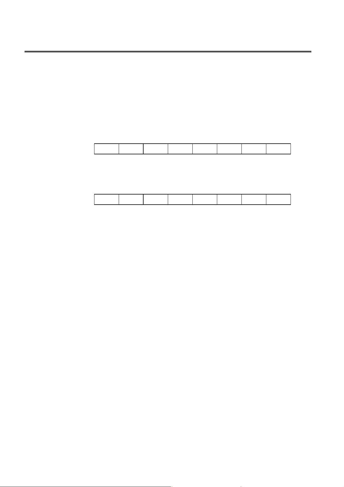
68
────────────────────────────────────────────────────
:MEASure:ITEM?
Queries the test parameter for response of the :MEASure? query
■
during normal testing.
Syntax
Function
:MEASure:ITEM?
Returns the test parameter to response the :MEASure? query during normal testing
as bits <MR0> and <MR1>.
The items of two registers (MR0 and MR1) are as follows.
Example
Response
If headers are on
If headers are off
The test parameters to response have been set to impedance (Z), phase angle (θ),
parallel capacitance (Cp), loss coefficient (D), series resistance(Rs), reactance (X).
128 64 32 16 8 4 2 1
bit 7 bit 6 bit 5 bit 4 bit 3 bit 2 bit 1 bit 0
Lp Ls D Cp Cs
Measurement Register 0 (MR0)
128 64 32 16 8 4 2 1
bit 7 bit 6 bit 5 bit 4 bit 3 bit 2 bit 1 bit 0
Unused Unused B X Rp G Rs Q
Measurement Register 1 (MR1)
:MEASURE:ITEM 53,18
53,18
θ
Y Z
Error
If the response message is longer than 300 bytes, a query error is generated.
────────────────────────────────────────────────────
・
5.4 Commands Specific to the 3532-50
3522-50
Page 75

69
────────────────────────────────────────────────────
:PARameter1
Sets the displayed parameters.
■
Syntax
<data>
:PARameter1 (2, 3, or 4) <data>
Z Impedance
Y Admittance
PHASe Phase angle
CS Series equivalent static capacitance
CP Parallel equivalent static capacitance
D Loss coefficient
LS Series equivalent inductance
LP Parallel equivalent inductance
Q Q factor
RS Series equivalent resistance
G Conductance
RP Parallel equivalent resistance
X Reactance
B Susceptance
OFF
(2, 3, or 4)
Function
Example
Error
Sets the displayed parameters.
Transmission :PARameter1 Z;:PARameter3 PHASe
The first parameter is set to impedance, and the third parameter is set to phase
angle.
If <data> is other than character data described above, an execution error occurs.
Executing this command while the open or short circuit compensation is
performed generates an execution error.
:PARameter1
Queries the displayed parameters.
■
Syntax
Function
:PARameter1 (2, 3, or 4)?
Returns the displayed parameters as character data.
Z, Y, PHASE, CS, CP, D, LS, LP, Q, RS, G, RP, X, B, OFF
(2, 3, or 4)
?
Example
Error
────────────────────────────────────────────────────
Response
If headers are on
If headers are off
The second parameter has been set to phase angle.
If the response message is longer than 300 bytes, a query error occurs.
:PARAMETER2 PHASE
PHASE
5.4 Commands Specific to the 3532-50
・
3522-50
Page 76

70
────────────────────────────────────────────────────
:PARameter1
■
Syntax
<data>
Function
Example
Note
Error
(2, 3, or 4)
Sets the number of displayed digits for the test parameters.
:PARameter 1 (2, 3, or 4):DIGit <data>
Numerical data in NR1 format
3to5
Sets the number of displayed digits for the first to fourth parameters.
Transmission :PARameter1:DIGit 4
The number of displayed digits for the first parameter is set to 4.
The response message for the ":MEASure?" query is always returned in 5 digits.
If <data> is other than numerical value described above, an execution error
occurs.
Executing this command while the open or short circuit compensation is
performed generates an execution error.
:DIGit
:PARameter1
Queries the number of displayed digits for the test parameters.
■
Syntax
Function
Example
Error
:PARameter1 (2, 3, or 4):DIGit?
Returns the number of displayed digits for the first to fourth parameters as
numerical data in NR1 format
Response
If headers are on
If headers are off
The number of displayed digits for the first parameter has been set to 4.
If the response message is longer than 300 bytes, a query error occurs.
(2, 3, or 4)
:DIGit?
:PARAMETER1:DIGIT 4
4
────────────────────────────────────────────────────
・
5.4 Commands Specific to the 3532-50
3522-50
Page 77
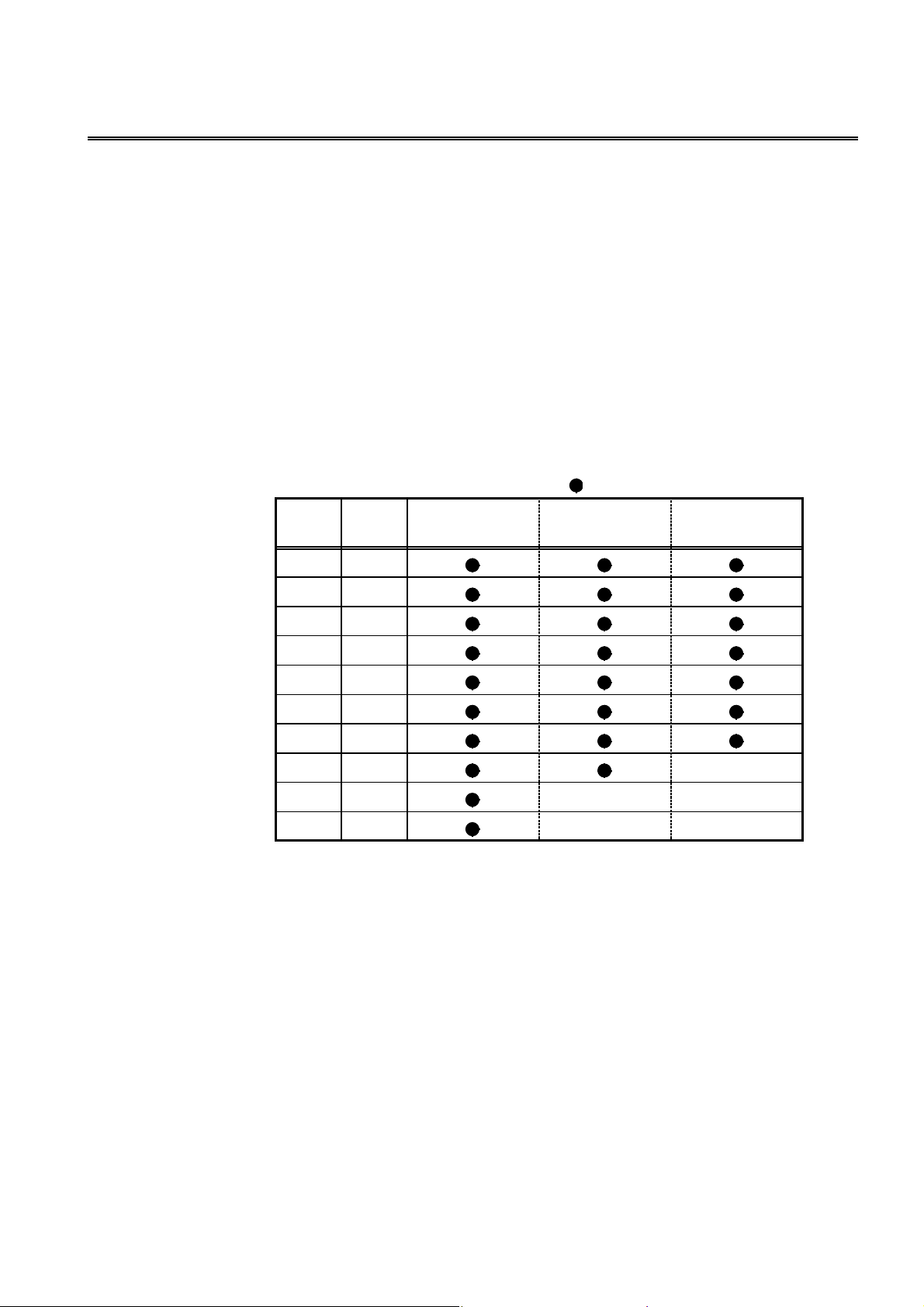
71
(
────────────────────────────────────────────────────
:RANGe
Sets the test range.
■
Syntax
<data>
:RANGe <data>
Numerical data in NR1 format
1to10
Function
Sets the test range.
・
・ The numerical value can be in NRf format, but any digits after the decimal point
will be rounded.
・ If this command is executed, the setting of the :RANGe:AUTO command is
automatically changed to OFF.
・ The numerical value corresponding to the test range and frequency which can be
set is as follows.
Range
number
1
2
3
4
Range
(Ω)
0.1
1
10
100
to 100.0 kHz
: settable / ---: cannot be set
100.1 kHz to
1.000 MHz
1.001 MHz to
5.000 MHz
Example
Transmission
The test range is set to 1 kΩ.
Error
If <data> is other than numerical value described above, an execution error
occurs.
Executing this command while the open or short circuit compensation is
performed generates an execution error.
5
6
7
8 1M
9
10
For 3532-50 If the test frequency is greater than 100 kHz, the range
1k
10 k
100 k
10 M --- --100 M --- ---
number 9 (10 MΩrange) cannot be set. If the test
frequency is greater than 1 MHz, the range number 8
1MΩrange)cannot be set.
:RANGe 5
---
────────────────────────────────────────────────────
・
5.4 Commands Specific to the 3532-50
3522-50
Page 78

72
────────────────────────────────────────────────────
:RANGe?
Queries the test range.
■
Syntax
Function
:RANGe?
Returns the test range setting as numerical value in NR1 format.
The numerical value corresponding to the test range and frequency which can be
set is as follows.
Range
number
1 0.1
2 1
3 10
4 100
5 1k
6 10 k
7 100 k
8 1M
9 10 M
10 100 M
Range (Ω)
Example
Response
If headers are on
If headers are off
The test range has been set to range 5 (1 kΩ).
Error
If the response message is longer than 300 bytes, a query error is generated.
:RANGE 5
5
────────────────────────────────────────────────────
・
5.4 Commands Specific to the 3532-50
3522-50
Page 79

73
────────────────────────────────────────────────────
:RANG e:AUTO
Enables and disables the auto-range function.
■
Syntax
<data>
Function
:RANGe:AUTO <data>
ON/OFF (character data)
Switches between automatic and manual setting of test range.
ON Switches the automatic setting.
OFF Switches the manual setting.
Example
Transmission
The test range is switched to automatic selection (auto-ranging).
Error
If <data> is other than character data described above, an execution error occurs.
Executing this command while the open or short circuit compensation is
performed generates an execution error.
:RANGe:AUTO?
■
Queries the autorange function enablement.
:RANGe:AUTO ON
Syntax
Function
:RANGe:AUTO?
Returns whether the test range is automatically set as character data.
ON, OFF
Examples
Response
If headers are on
If headers are off
Error
If the response message is longer than 300 bytes, a query error is generated.
:RANGE:AUTO ON
ON
────────────────────────────────────────────────────
・
5.4 Commands Specific to the 3532-50
3522-50
Page 80

74
────────────────────────────────────────────────────
:SAVE
Saves the test conditions in specified panel number.
■
Syntax
<data>
:SAVE <number>, <name>
<number> Numerical data in NR1 format between 1 and 30
<name> Character data, up to 20 characters
Function
Saves the test conditions in specified panel number with name to be saved.
・
・ The numerical value can be in NRf format, but any digits after the decimal point
will be rounded.
・ The capital letters, numbers, and hyphen can be used.
・ If 21 or more characters are entered, the first 20 characters are used.
Example
Transmission :SAVE 3,TEST1
The test condition is saved as a name "TEST1" in panel number 3.
Error
If <data> is other than numerical value and character data described above, an
execution error occurs.
Executing this command while the open or short circuit compensation is
performed generates an execution error.
:SAVE?
Queries the panel number saved.
■
Syntax
<data>
Function
:SAVE? <data>
Numerical data in NR1 format between 0 and 30
Returns 1 when the test conditions are saved in specified panel number, and
・
returns 0 when not saved.
・ The numerical value can be in NRf format, but any digits after the decimal point
will be rounded.
・ The response message has no headers.
Example
Transmission :SAVE? 3
Response 1
The test condition is saved in panel number 3.
Error
If <data> is other than numerical value and character data described above, an
execution error occurs.
────────────────────────────────────────────────────
・
5.4 Commands Specific to the 3532-50
3522-50
Page 81

75
────────────────────────────────────────────────────
:SCALe
Enables and disables the scaling function.
■
Syntax
<data>
Function
Example
:SCALe <data>
ON/OFF
Enables and disables the scaling function.
Transmission :SCALe ON
Enables the scaling function.
Error
If <data> is other than character data described above, an execution error occurs.
Executing this command while the open or short circuit compensation is
performed generates an execution error
:SCALe?
Queries the scaling function.
■
Syntax
Function
:SCALe?
Returns the setting of scaling function enablement as character data.
.
ON, OFF
Example
Response
If headers are on
If headers are off
Error
If the response message is longer than 300 bytes, a query error occurs.
:SCALE ON
ON
────────────────────────────────────────────────────
・
5.4 Commands Specific to the 3532-50
3522-50
Page 82

76
────────────────────────────────────────────────────
:SCALe:FVALue
Sets the first parameters (a and b) in the scaling function.
■
Syntax
<data>
Function
:SCALe:FVALue <a>, <b>
Numerical data in NR3 format
Sets the first parameters (a and b values) in the scaling function.
・
・ For calculation equation of the scaling function, see the Instruction Manual of
main unit.
Example
Transmission :SCALe:FVALue 2.0000E+00,1.0000E+00
Sets a value to 2.0000, and b value to 1.0000.
Error
If <data> is other than numerical data described above, an execution error occurs.
Executing this command while the open or short circuit compensation is
performed generates an execution error
:SCALe:FVALue?
Queries the first parameters (a and b) in the scaling function.
■
Syntax
:SCALe:FVALue?
.
Function
Returns the setting of the first parameters (a and b values) in the scaling function
as a numerical value in NR3 format.
Example
Response
If headers are on
If headers are off
Error
If the response message is longer than 300 bytes, a query error occurs.
:SCALE:FVALUE 2.0000E+00,1.0000E+00
2.0000E+00,1.0000E+00
────────────────────────────────────────────────────
・
5.4 Commands Specific to the 3532-50
3522-50
Page 83

77
────────────────────────────────────────────────────
:SCALe:SVALue
Sets the second parameters (a and b) in the scaling function.
■
Syntax
<data>
Function
:SCALe:SVALue <a>, <b>
Numerical data in NR3 format
Sets the second parameters (a and b values) in the scaling function.
・
・ For calculation equation of the scaling function, see the Instruction Manual of
main unit.
Example
Transmission :SCALe:SVALue 2.0000E+00,1.0000E+00
Sets a value to 2.0000, and b value to 1.0000.
Error
If <data> is other than numerical data described above, an execution error occurs.
Executing this command while the open or short circuit compensation is
performed generates an execution error.
:SCALe:SVALue?
Queries the second parameters (a and b) in the scaling function.
■
Syntax
:SCALe:SVALue?
Function
Returns the setting of the second parameters (a and b values) in the scaling
function as a numerical value in NR3 format.
Example
Response
If headers are on
If headers are off
Error
If the response message is longer than 300 bytes, a query error occurs.
:SCALE:SVALUE 2.0000E+00,1.0000E+00
2.0000E+00,1.0000E+00
────────────────────────────────────────────────────
・
5.4 Commands Specific to the 3532-50
3522-50
Page 84

78
────────────────────────────────────────────────────
:SPEEd
Sets the testing speed.
■
Syntax
<data>
Function
Example
Error
:SPEEd <data>
FAST/NORMal/SLOW/SLOW2 (character data)
Sets the testing speed.
Transmission
If <data> is other than character data described above, an execution error occurs.
Executing this command while the open or short circuit compensation is
performed generates an execution error.
:SPEEd?
Queries the testing speed.
■
Syntax
Function
:SPEEd?
Returns the setting of testing speed as character data.
FAST, NORMAL, SLOW, SLOW2
:SPEEd NORMal
Example
Response
If headers are on
If headers are off
Error
If the response message is longer than 300 bytes, a query error is generated.
:SPEED NORMAL
NORMAL
────────────────────────────────────────────────────
・
5.4 Commands Specific to the 3532-50
3522-50
Page 85

79
────────────────────────────────────────────────────
:TRIGger
Sets the type of trigger.
■
Syntax
<data>
Function
:TRIGger <data>
INTernal/EXTernal (character data)
Sets the type of trigger.
INTernal Internal trigger mode
EXTernal External trigger mode
Example
Transmission
The trigger mode is set to internal trigger.
Error
If <data> is other than character data described above, an execution error occurs.
Executing this command while the open or short circuit compensation is
performed generates an execution error.
:TRIGger?
Queries the trigger setting.
■
:TRIGger INTernal
Syntax
Function
:TRIGger?
Returns the trigger setting as character data.
INTERNAL/EXTERNAL
Example
Response
If headers are on
If headers are off
The trigger mode has been set to internal triggering.
Error
If the response message is longer than 300 bytes, a query error is generated.
:TRIGGER INTERNAL
INTERNAL
────────────────────────────────────────────────────
・
5.4 Commands Specific to the 3532-50
3522-50
Page 86

80
────────────────────────────────────────────────────
:TRIGger:DELA y
Sets the trigger delay time.
■
Syntax
<data>
Function
:TRIGger:DELAy <data>
Numerical data in NR2 format from 0.00 to 9.99.
Sets the trigger delay time.
・
・ The numerical value can be in NRf format, but rounding is performed for figures
beyond the last valid decimal place.
Example
Transmission :TRIGger:DELAy 0.05
The trigger delay time is set to 50 ms.
Error
If <data> is other than numerical value described above, an execution error
occurs.
Executing this command while the open or short circuit compensation is
performed generates an execution error.
:TRIGger:DELA y?
Queries the trigger delay time.
■
Syntax
Function
:TRIGger:DELAy?
Returns the current setting of trigger delay time as a numerical value in NR2
format from 0.00 to 9.99.
Example
Response
If headers are on
If headers are off
The trigger delay time has been set to 50 ms.
Error
If the response message is longer than 300 bytes, a query error is generated.
:TRIGGER:DELAY 0.05
0.05
────────────────────────────────────────────────────
・
5.4 Commands Specific to the 3532-50
3522-50
Page 87

81
────────────────────────────────────────────────────
:User:IDENtity
Set the user ID.
■
Syntax
<data>
Function
:USER:IDENtity <data>
For example: AB-9593
・ The user can set an identity code.
・ The ID is backed up in the same way as the main unit settings.
・ The capital and lowercase letters, digits 0 to 9, and hyphen can be used.
・ If an ID of eight or more characters is entered, the first seven characters are used.
・ The user ID is cleared by the system reset of the main unit.
Example
Transmission
This sets the user ID to "AB-9593"
Error
If <data> is other than character data described above, a command error occurs.
:User:IDENtity?
Queries the user ID.
■
:USER:IDEN AB-9593
Syntax
Function
Example
USER:IDENtity?
Returns a user ID as seven characters data <data>.
Response
If headers are on
If headers are off
Error
・ If the response message is longer than 300 bytes, a query error is generated.
:USER:IDENTITY AB-9593
AB-9593
────────────────────────────────────────────────────
・
5.4 Commands Specific to the 3532-50
3522-50
Page 88

82
1 2
1 2
────────────────────────────────────────────────────
5.5 Response Format for Queries as Numerical Value
(1)Testvalue
1. The response formats for |Z| (impedance),|Y| (admittance), Cs (static capacitance in
series equivalent circuit mode), Cp (static capacitance in parallel equivalent circuit
mode), Ls (inductance in series equivalent circuit mode), Lp (inductance in parallel
equivalent circuit mode), Rs (effective resistance in series equivalent circuit mode),
G (conductance), Rp (effective resistance in parallel equivalent circuit mode), X
(reactan ce), B (susceptance) are as follows. (in NR3 format)
□.□□□□E±□□
1 Mantissa Five digits and decimal point
2 Exponent Two digits
When the value is overflow or underflow, the following value is displayed.
Overflow 99999E+99
Underflow -99999E+99
2. The response formats (in NR2 format) for θ(phase angle).
(-)
□□□.□□
(-)
□□.□□
(-)□.
□□
1 Sign Only when the value is negative, minus (-) is prefixed.
2 Numerical Up to the second decimal point
When the value is overflow or underflow, the following value is displayed.
Overflow 999.9
Underflow -999.9
3. The response formats (in NR2 format) for D (loss coefficient)
□.□□□□□
Up to the fifth decimal point
When the value is overflow or underflow, the following value is displayed.
Overflow 999999
Underflow -999999
4. The response formats (in NR2 format) for Q (Q factor)
────────────────────────────────────────────────────
5.5 Response Format for Queries as Numerical Value
□.□□
□□.□□
□□□.□□
Up to the second decimal point
When the value is overflow or underflow, the following value is displayed.
Overflow 9999
Underflow -9999
Page 89

83
1 2
1 2
1 2 3
────────────────────────────────────────────────────
(2) Frequency response format (in NR3 format)
□.□□□E±□□
□□.□□E±□□
□□□.□E±□□
1 Mantissa Three or four digits and decimal point
2 Exponent Two digits
(3) Voltage response format (in NR2 format)
□.□□□
Four digits and decimal point
(4) Current response format (in NR3 format)
□.□□□E±□□
1 Mantissa Four digits and decimal point
2 Exponent Two digits
(5) Trigger delay response format (in NR2 format)
□.□□
Mantissa Three digits and decimal point
(6) Reference value (percentage value), upper and lower limit values
(absolute value), scaling correction coefficient for comparator (in
NR3 format)
(-)□.
□□□□E±□□
(-)
□□.□□□E±□□
(-)
□□□.□□E±□□
(-)
□□□□.□E±□□
────────────────────────────────────────────────────
1 Sign When the value is negative, minus (-) is prefixed.
2 Mantissa Five digits and decimal point
3 Exponent two digits
5.5 Response Format for Queries as Numerical Value
Page 90
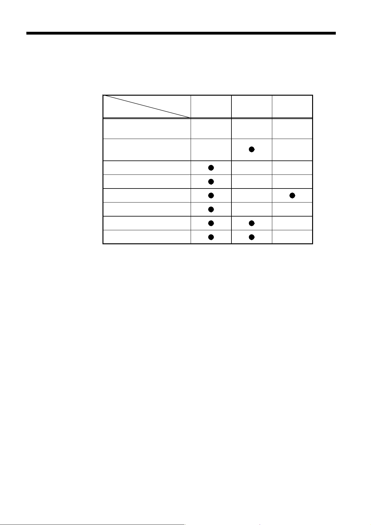
84
Initializati
────────────────────────────────────────────────────
5.6 Initialization Items
The following table shows which items are initialized and which not, under
various conditions.
on
Item
method
RS-232C Communication
conditions *1
Device specific functions
(ranges etc.)
Output queue --- --Input buffer --- --Event registers
Current path --- --Headers on/off --Measurement resister ---
*1 When the power is turned on, item is discriminated.
*2 Except the PON bit (bit 7).
Power on
--- --- ---
--- ---
*2
*RST
command
---
*CLS
command
────────────────────────────────────────────────────
5.6 Initialization Items
Page 91

85
────────────────────────────────────────────────────
Chapter 6
Sample Programs
The following sample programs are all written for the Microsoft Quick
BASIC.
For more details on the Quick BASIC, refer to the Quick BASIC
documentation.
All commands in the sample programs are used in the short form, and the
communication condition setting switches of the 3532-50 or 3522-50 is
taken as 00000010 (baud rate: 9600bps, data length: 8 bits, parity: non, stop
bit: 1 bit, delimiter: CR).
(1) Open- and short-circuit compensation
Summary This program carries out open- and short-circuit compensation on the 3532-
50or 3522-50.
Program List
10 OPEN "COM1:9600,N,8,1" FOR RANDOM AS #1
20 PRINT #1, ":HEAD OFF"
*
30 PRINT #1, "
40 CORR.OPEN:
50 INPUT "Prepare unit for open circuit compensation, then press Enter", A$
60 PRINT "Collecting open circuit compensation data"
70 PRINT #1, ":CORR:OPEN ALL"
80 OPEN.LOOP:
90 PRINT #1, ":ESR0?"
100 INPUT #1, A
110 IF (A AND 1) = 0 THEN GOTO OPEN.LOOP
120 PRINT #1, "*ESR?"
130 INPUT #1, A
140 IF (A AND 8) = 0 THEN GOTO CORR.SHORT
150 PRINT "Open circuit compensation failed"
160 GOTO CORR.OPEN
170 CORR.SHORT:
180 INPUT "Prepare unit for short circuit compensation, then press Enter", A$
190 PRINT "Collecting short circuit compensation data"
200 PRINT #1, ":CORR:SHOR ALL"
210 SHORT.LOOP:
220 PRINT #1, ":ESR0?"
230 INPUT #1, A
240 IF (A AND 1) = 0 THEN GOTO SHORT.LOOP
250 PRINT #1, "*ESR?"
260 INPUT #1, A
270 IF (A AND 8) = 0 THEN GOTO CORR.END
CLS"
────────────────────────────────────────────────────
Page 92

86
────────────────────────────────────────────────────
280 PRINT "Short circuit compensation failed"
290 GOTO CORR.SHORT
300 CORR.END:
310 PRINT "Compensation operations completed"
320 CLOSE
330 END
Program
comments
Line Comments
10 Open the RS-232C circuit file.
20 Switch off headers for the response message.
30 Clear bits of each event registers.
70 Execute open circuit compensation (at all the test frequencies).
90-110 Wait until the bit for the compensation completed is 1.
120-140 When the valid data cannot be obtained, the bit 3 of SESR is 1.
320 Close the RS-232C circuit file.
────────────────────────────────────────────────────
Page 93

87
────────────────────────────────────────────────────
(2) Basic settings and testing
Summary This program selects the test conditions for measurement on the 3532-50or
3522-50.
・It carries out a single test measurement, and displays the result on the
screen.
・It also displays the monitored voltage and current values on the screen.
Program List
Program
comments
10 OPEN "COM1:9600,N,8,1" FOR RANDOM AS #1
20 PRINT #1,":TRIG EXT"
30 PRINT #1,":AVER 8"
40 PRINT #1,":FREQ 1.234E3"
50 PRINT #1,":RANG:AUTO ON"
60 PRINT #1,":LEV V"
70 PRINT #1,":LEV:VOLT 1.00"
80 PRINT #1,":TRIG:DELA 0.02"
90 PRINT #1,":SPEE SLOW"
100 PRINT #1,":MEAS:ITEM 5,18"
110 PRINT #1,"*TRG;:ME AS?"
120 LINE INPUT #1,A$
130 PRINT #1,":DISP:MONI?"
140 LINE INPUT #1,B$
150 PRINT A$
160 PRINT B$
170 CLOSE
180 END
Line Comments
10 Open the RS-232C circuit file.
20 Select external trigger mode.
30 Set the count for averaging to 8.
40 Set the test frequency to 1.234 kHz.
50 Enable auto-ranging.
60 Select voltage measurement.
70 Set the test voltage to 1 V.
80 Set the trigger delay time to 20 ms.
90 Set the testing speed to SLOW.
100 Make a setting for Z (impedance), θ(phase angle), Rs (series
110 Query the sampling data and measurement value.
130 Query the monitored value for the test signal.
150-160 Display the test results.
170 Close the RS-232C circuit file.
equivalent resistance), X (reactance) to return.
────────────────────────────────────────────────────
Page 94

88
────────────────────────────────────────────────────
(3) Saving the 3532-50 settings using the panel save function
Summary This program makes the settings for the 3532-50 and saves the settings to
the panel number 1 as "TEST1".
Program List
Program
comments
10 OPEN "COM1:9600,N,8,1" FOR RANDOM AS #1
20 PRINT #1,":FREQ 100E3"
30 PRINT #1,":LEV V"
40 PRINT #1,":LEV:VOLT 1.00;CVOLT 0.50;CCURR 5.00E-3"
50 PRINT #1,":LIM OFF"
60 PRINT #1,":LIM:CURR 15.00E-3;VOLT 3.00"
70 PRINT #1,":RANG:AUTO ON"
80 PRINT #1,":TRIG INT"
90 PRINT #1,":TRIG:DELA 0.02"
100 PRINT #1,":AVER 2"
110 PRINT #1,":SPEE SLOW"
120 PRINT #1,":BEEP:KEY ON;COMP NG"
130 PRINT #1,":PAR1 Z;:PAR2 PHAS"
140 PRINT #1,":PAR3 CP;:PAR4 D"
150 PRINT #1,":SAVE 1,TEST1"
160 CLOSE
170 END
Line Comments
10 Open the RS-232C circuit file.
20 Set the test frequency to 100 kHz.
30 Select the voltage test signal level.
40 Make the following settings using the current path.
V(open circuit voltage): 1 V
CV(constant voltage): 0.5 V (value setting only)
CC(constant current): 5 mA (value setting only)
50 Set the limit value setting function to OFF
60 Set the current limit value to 15 mA (value setting only).
Set the voltage limit value to 3 V (value setting only).
70 Enable auto-ranging.
80 Select internal trigger mode.
90 Set the trigger delay time to 20 ms.
100 Set the count for averaging to 2.
110 Set the testing speed to SLOW.
120 Set the beep sound.
130-140 Set displayed parameters.
150 Save the settings to the panel number 1.
160 Close the RS-232C circuit file.
────────────────────────────────────────────────────
Page 95

89
────────────────────────────────────────────────────
(4) Carrying out comparator testing
Summary This program first makes the comparator settings.
At the end of testing, it displays the numbers of the samples which were
outside the comparator limit.
Sample nos. decided HI for CP:2 5
Sample nos. decided LOW for CP:
All measured results
Sample number: 1 3.8686E-04 .34823
Sample number: 2 3.8704E-04 .34823
Sample number: 3 3.8681E-04 .34843
Sample number: 4 3.8694E-04 .34804
Sample number: 5 3.8698E-04 .34823
Program List
10 OPEN "COM1:9600,N,8,1" FOR RANDOM AS #1
20 PRINT #1, ":PAR1 CP;:PAR3 D"
30 PRINT #1, ":TRIG EXT"
40 PRINT #1, ":HEAD OFF"
50 PRINT #1, ":FREQ 1.234E3"
60 PRINT #1, ":RANG:AUTO ON"
70 PRINT #1, ":LEV CV;:LEV:CVOLT 1.00"
80 PRINT #1, ":COMP:FLIM:MODE ABS;ABS 386 .80E-6,386.95E-6"
90 PRINT #1, ":COMP:SLIM:MODE PER;PER 1.0000,OFF,OFF"
100 NUM.SET:
110 INPUT "Number of samples to m easure:"; X
120 IF X < = 0 THEN GOTO NUM.SET
130 OPTION BASE 1
140 DIM F.ALL(X), CP(X), F.CP(X), D(X), F.D(X)
150 PRINT #1, ":COMP ON"
160 INPUT "Prepare sample, then press Enter", A$
170 CLS
180 I = 1
190 MEAS.LOOP:
200 PRINT #1, "*TRG;:MEAS?"
210 INPUT #1, F.ALL(I), CP(I), F.CP(I), D(I), F.D(I)
220 I = I + 1
230 IF I > X THEN GOTO MEAS.END
240 CLS
250 PRINT "Prepare sample number ";I;
260 INPUT ", then press Enter", A$
270 GOTO MEAS.LOOP
280 MEAS.END:
290 PRINT #1, ":COMP OFF"
300 CLS
310 PRINT "Sample nos. decided HI for CP:";
320 FOR I = 1 TO X
330 IF F.CP(I) = 1 THEN PRINT I;
340 NEXT I
350 PRINT
360 PRINT "Sample nos. decided LOW for CP:";
370 FOR I = 1 TO X
380 IF F.CP(I) = -1 THEN PRINT I;
390 NEXT I
400 PRINT
────────────────────────────────────────────────────
Page 96

90
────────────────────────────────────────────────────
410 PRINT
420 PRINT "All measured results"
430 FOR I = 1 TO X
440 PRINT "Sample number"; I, CP(I), D(I)
450 NEXT I
460 CLOSE
470 END
Program
comments
Line Comments
10 Open the RS-232C circuit file.
20 Set the first parameter to Cp,and the second parameter to D.
30 Select external trigger mode.
40 Switch off headers for the response message.
50 Set the test frequency to 1.234 kHz.
60 Enable auto-ranging.
70 Set the constant voltage to 1 V.
80 Set the first parameter for the comparator function as absolute
value (the current path is used in this settings).
90 Set the second parameter for the comparator function as
percentage value.Since both settings of lower and upper limits are
OFF,the comparator result is always IN (within limits). Input
appropriate reference value (the current path is also used in this
settings).
130-140 Initialize variables.
150 Switch on the comparator function.
190-280 Measurement loop
Returns data as total result, measurement value of CP, CP
decision, measurement value of D, D decision in order.
290 Switch off the comparator function.
310-340 Check HI decision for CP.
360-390 Check LOW decision for CP.
460 Close the RS-232C circuit file.
────────────────────────────────────────────────────
Page 97

91
────────────────────────────────────────────────────
(5) Frequency characteristics measurement for impedance
Summary This program measures the impedance frequency characteristics at various
frequencies.
It outputs the test result to a file.
The number of test point: 34
50/ 60/ 80 Hz
100/ 120/ 150/ 200/ 250/ 300/ 400/ 500/ 600/ 800 Hz
1/ 1.2/ 1.5/ 2/ 2.5/ 3/ 4/ 5/ 6/ 8 kHz
10/ 12/ 15/ 20/ 25/ 30/ 40/ 50/ 60/ 80/ 100 kHz
Program List
10 OPEN "COM1:9600,N,8,1" FOR RANDOM AS #1
20 PRINT #1, ":COMP OFF;:TRIG EXT"
30 PRINT #1, ":LEV V;:LEV:VOLT 1.00"
40 PRINT #1, ":MEAS:ITEM 1,0"
50 PRINT #1, ":HEAD OFF"
60 OPTION BASE 1
70 PNT = 34
80 DIM TABLE(10), F(PNT), Z(PNT)
90 RESTORE F.DATA
100 F.DATA:
110 DATA 1,1.2,1.5,2,2.5,3,4,5,6,8
120 FOR I = 1 TO 10
130 READ TABLE(I)
140 NEXT I
150 EX = 10: T = 8
160 FOR I = 1 TO PNT
170 F(I) = EX * TABLE(T)
180 PRINT #1, ":FREQ " + STR$(F(I))
190 PRINT #1, "*TRG;:MEAS?"
200 INPUT #1, Z(I)
210 PRINT F(I), Z(I)
220 IF T = 10 THEN T = 1: EX = EX * 10 ELSE T = T + 1
230 NEXT I
240 GOSUB SAVE.DATA:
250 CLS
260 CLOSE
270 END
280 SAVE.DATA:
290 INPUT "Input the file name to be saved.", F. NAME$
300 OPEN F.NAME$ FOR OUTPUT AS #2
310 FOR I = 1 TO PNT
320 PRINT #2, F(I); ","; Z(I)
330 NEXT I
340 CLOSE #2
350 RETURN
────────────────────────────────────────────────────
Page 98

92
────────────────────────────────────────────────────
Program
comments
Line Comments
10 Open the RS-232C circuit file.
20 Switch off the comparator function, and select external trigger
mode.
30 Set the measured voltage to 1V.
40 Make a settings to response the parameter for Z by using the
:MEAS? query.
90-140 Set frequency mantissa table.
150 Measure from EX*TABLE(T=8) = 50 (Hz)
160-230 Measurement loop
170-180 Transmit character data by transforming the numerical values.
190 Query the sampling data and measurement value.
220 Change the frequency value to the new one.
240 Save the test frequency and test results to the file.
280-350 Routines to save the measurement value to the file.
────────────────────────────────────────────────────
Page 99

93
────────────────────────────────────────────────────
Chapter 7
Troubleshooting
If the RS-232C appears to be malfunctioning, refer to the information below
before calling for servicing.
Symptom Cause / Treatment
The RS-232C has stopped
working completely.
Transmission on the RS-232C
is not taking place properly.
When attempting to read data
using a BASIC INPUT
statement, the RS-232C bus
hangs.
Although a command has been
transmitted, nothing has
happened.
The amount of data read in is
insufficient.
Are the cables properly connected?
Are all the devices powered on?
Has the communication condition been correctly set?
Is the controller delimiter set correctly?
(Refer to Section 4.5, "Delimiter".)
Be sure to transmit one query before each INPUT statement.
Have any of these transmitted queries resulted in as error?
Using the "*ESR?" query, inspect the standard event status
register, and check what type of error has occurred.
Using the "ERRor?" query, and check whether transmission error
occurred on the RS-232C.
If the data includes one or more commas, then try using a LINE
INPUT statement.
Has an error occurred?
Sending several queries,
produces only one response.
────────────────────────────────────────────────────
Send the queries one at a time, and read the responses
individually.
When you want to read them in all at once, try doing so by
putting them all on one line separated by the message separator
character.
Page 100

94
────────────────────────────────────────────────────
Symptom Cause / Treatment
Have the response messages from 3532-50・3522-50 exceeded the
Although a response has been
read in, the data does not
appear.
buffer capacity of the computer?
Try dividing up their reading in, by increasing the number of
variables of the INPUT statement.
The response message to a
query differs from the display
on the front panel of the 353250・3522-50.
Beeper sounds when *TRG
command is transferred.
Service
If damage is suspected, check the "Troubleshooting" section before
contacting your dealer or Hioki representative.
Due to the response message being produced at the instant that
the 3532-50・3522-50 receives the query, there is a possibility that
it may not agree with the display at the instant that the controller
reads it in.
Is the trigger is set to internal trigger?
*TRG command can be used for the external trigger setting.
For the internal trigger setting, an execution error occurs.
────────────────────────────────────────────────────
 Loading...