

Page 1

INSTRUCTION MANUAL
For 8835(-01), 8826, 8841, 8842
MEMORY HiCORDER
INTERFACE
9557 RS-232C CARD
9558 GP-IB CARD
Page 2

Page 3

Contents
Introduction i
Safety Notes i
Chapter Summary ii
Chapter 1 GP-IB and RS-232C Interfaces 1
1.1 GP-IB Interface 1
1.1.1 Outline 1
1.1.2 Specification
1.2 RS-232C Interface 4
1.2.1 Outline 4
1.2.2 Specification
Chapter 2 Method of Operation 7
2.1 Basic Operational Procedure 7
2.2 Cable Connection
2.3 Setup Procedure 11
2.3.1 GP-IB Setup Procedure 11
2.3.2 RS-232C Setup Procedure
2.4 Receive and Send Protocols 15
2.5 The Status Byte and the Event Registers 19
2.6 The Input Buffer and the Output Queue
2.7 Others
2.7.1 GP-IB 24
13
23
24
2
4
8
2.7.2 RS-232C
25
Chapter 3 Commands 27
3.1 Command Summary 27
3.1.1 Standard Commands Specified by IEEE 488.2 27
3.1.2 Specific Commands
3.2 Detailed Explanation of the Commands 57
3.2.1 Explanation 57
3.2.2 Standard Commands Stipulated by IEEE 488.2
3.2.3 Specific Commands
28
59
65
Page 4

Chapter 4 Example Programs 169
4.1 Visual Basic Example Programs 169
4.1.1 GP-IB Example Programs 169
4.1.2 RS-232C Example Programs
179
Appendix Appendix I
Appendix 1 IEEE 488.2-1987 Appendix I
Appendix 2 Troubleshooting the GP-IB Faults Appendix IV
Appendix 3 Troubleshooting the RS-232C Faults Appendix V
Page 5
────────────────────────────────────────────────────
R
R
N
I
S
ntroduction
Thank you for purchasing the HIOKI "9557 RS-232C CARD / 9558 GP-IB
CARD" . To obtain maximum performance from the product, please read this
manual first, and keep it handy for future reference.
When using the HIOKI MEMORY HiCORDER can be used with the HIOKI
"9557 RS-232C CARD / 9558 GP-IB CARD" except following products, reffer to
the communication comands manual (Flopply disk) supplied with the
MEMORY HiCORDER.
■ The products consultable this manual:
8826, 8835, 8835-01, 8841, 8842
afety Notes
i
This manual contains information and warnings essential for safe operation of
the product and for maintaining it in safe operating condition. Before using
the product, be sure to carefully read the following safety notes.
DANGE
This product is designed to conform to IEC 61010 Safety Standards, and
has been thoroughly tested for safety prior to shipment. However,
mishandling during use could result in injury or death, as well as damage
to the product. Be certain that you understand the instructions and
precautions in the manual before use. We disclaim any responsibility for
accidents or injuries not resulting directly from product defects.
Safety symbol
The following symbols in this manual indicate the relative importance of
cautions and warnings.
In the manual, the symbol indicates particularly important
information that the user should read before using the product.
DANGE
CAUTIO
NOTE
────────────────────────────────────────────────────
Indicates that incorrect operation presents an extreme hazard that
could result in serious injury or death to the user.
Indicates that incorrect operation presents a possibility of injury to
the user or damage to the product.
Indicates advisory items related to performance or correct operation
of the product.
Page 6

ii
C
────────────────────────────────────────────────────
hapter Summary
Chapter 1 GP-IB and RS-232C interfaces
Contains the functions and specifications of both the interfaces.
Chapter 2 Method of operation
Describes the operation procedures of both the interfaces.
Chapter 3 Commands
Describes the details of all the commands th at can be used.
Chapter 4 Example programs
Describes the program to operate GP-IB interface.
Appendix
Contains the information related to the IEEE488.2-1987 standard.
────────────────────────────────────────────────────
Page 7

1
1
1
C
s
1
────────────────────────────────────────────────────
Chapter
1
2
.1 GP-IB Interface
.1.1 Outline
The GP-IB (General Purpose Interface Bus) was developed as an interface for
general use by programmable instrumentation, and as an interface is rich in
expandability and has many distinctive features.
There are various interfaces with specific names apart from the GP-IB, such
as the IEEE-488 bus, the IEC bus, and the HP-IB which is an internal
standard within the Hewlett-Packard Company. These are basically the same
standard, but, because the number of connector pins and the arrangement of
the signals and so on differ, much care should be exercised.
GP-IB and RS-232
Interface
3
4
5
6
7
8
9
10
In this explanation of management and operation, only the GP-IB related
resources of the 8835 and 8826 will be described.
If more detailed knowledge of the GP-IB interface is required, reference should
be made to the following literature:
The Institute of Electrical and Electronics Engineers, Inc.: "IEEE Standard
Digital Interface for Programmable Instrumentation", IEEE Std 488.1-1987,
IEEE Std 488.2-1987 (1987)
────────────────────────────────────────────────────
1.1 GP-IB Interface
11
12
13
14
A
Page 8

2
1
r
l
────────────────────────────────────────────────────
.1.2 Specification
Standards
IEEE Standard 488.1-1987
IEEE Standard 488.2-1987
Interface Functions
Function Implementation
SH1 SH (Source Handshake) - All Functions
AH1 AH (Acceptor Handshake) - All Functions
T5 Basic Talk Function, Serial Poll Function, Talk Only Function
MLA (My Listen Address) Talk Release Function
L4 Basic Listener Function
MTA (My Talk Address) Listen Release Function
SR1 SR (Service Request) - All Functions
GP-IB Signal Lines
Bus Signal Lines Remarks
DIO 1 (Data Input Output 1)
DIO 2 (Data Input Output 2)
DIO 3 (Data Input Output 3)
Data
bus
DIO 4 (Data Input Output 4)
DIO 5 (Data Input Output 5)
DIO 6 (Data Input Output 6)
DIO 7 (Data Input Output 7)
DIO 8 (Data Input Output 8)
DAV (Data Valid)
Transfe
bus
NRFD (Not Ready For Data)
NDAC (Not Data Accepted) Input completed signal.
RL1 RL (Remote/Local) - All Functions
PP0 PP (Parallel Poll) - No Function
DC1 DC (Device Clear) - All Functions
DT0 DT (Device Trigger) - No Function
C0 C (Control) - No Function
Apart from input and output of data, these are used
for input and output of interface messages and
device messages.
Signal which indicates data bus
information validity.
Input preparation completed
signal.
These perform
acceptor and
source
handshake.
Signal which indicates that the information on the
ATN (Attention)
data bus is an interface message or a device
message.
Contro
bus
────────────────────────────────────────────────────
1.1 GP-IB Interface
IFC (Interface Clear)
SRQ (Service Request) Signal which requests a non-synchronous service.
REN (Remote Enable)
EOI (End or Identify) Indicates the last byte of data.
Signal which sets the interface bus system to the
initial condition.
Signal which performs changeover of remote and
local control.
Page 9

3
────────────────────────────────────────────────────
Connector Pin Assignment
RC40-24RR (made by HIROSE) or compatible.
Fig. 1.1 Pin arrangement diagram for the GP-IB interface connector
Pin
number
1 DIO1 13 DIO5
2 DIO2 14 DIO6
3 DIO3 15 DIO7
4 DIO4 16 DIO8
5 EOI 17 REN
Name of signal line
Pin
number
Name of signal line
1
2
3
4
5
6
7
6 DAV 18 GND
7 NRFD 19 GND
8 NDAC 20 GND
9 IFC 21 GND
10 SRQ 22 GND
11 ATN 23 GND
12 SHIELD 24 LOGIC GND
8
9
10
11
12
13
────────────────────────────────────────────────────
1.1 GP-IB Interface
14
A
Page 10

4
1
1
1
────────────────────────────────────────────────────
.2 RS-232C Interface
.2.1 Outline
RS-232C is a serial interface standard defined by the EIA (Electronic
Industries Association). It specifies the interface parameters for
communication between a DTE (Data Terminal Equipment) and DCE (Data
Communications Equipment).
The MEMORY HiCORDER incorporates a partial implementation of the RS232C specification (only certain signal lines) to allow data exchange and
remote control using a personal computer.
.2.2 Specification
Standard
EIA RS-232C
General Specifications
Communication mode Full-duplex
Synchronization Start-stop synchronization
Transfer rate 1200, 2400, 4800, 9600, 19200, 38400, 57600, 115200
(bits/s), (set from the setting screen of the unit)
Start bit 1bit
Stop bits 1 or 2 bits
(set from the setting screen of the unit)
Data length 7 or 8 bits
Parity None, even, or odd
(set from the setting screen of the unit)
Delimiter LF, CR+LF
Flow control Xon/Xoff, hardware, none
────────────────────────────────────────────────────
1.2 RS-232C Interface
Page 11
5
I
s
s
l
I
s
s
I
s
s
l
I
s
s
────────────────────────────────────────────────────
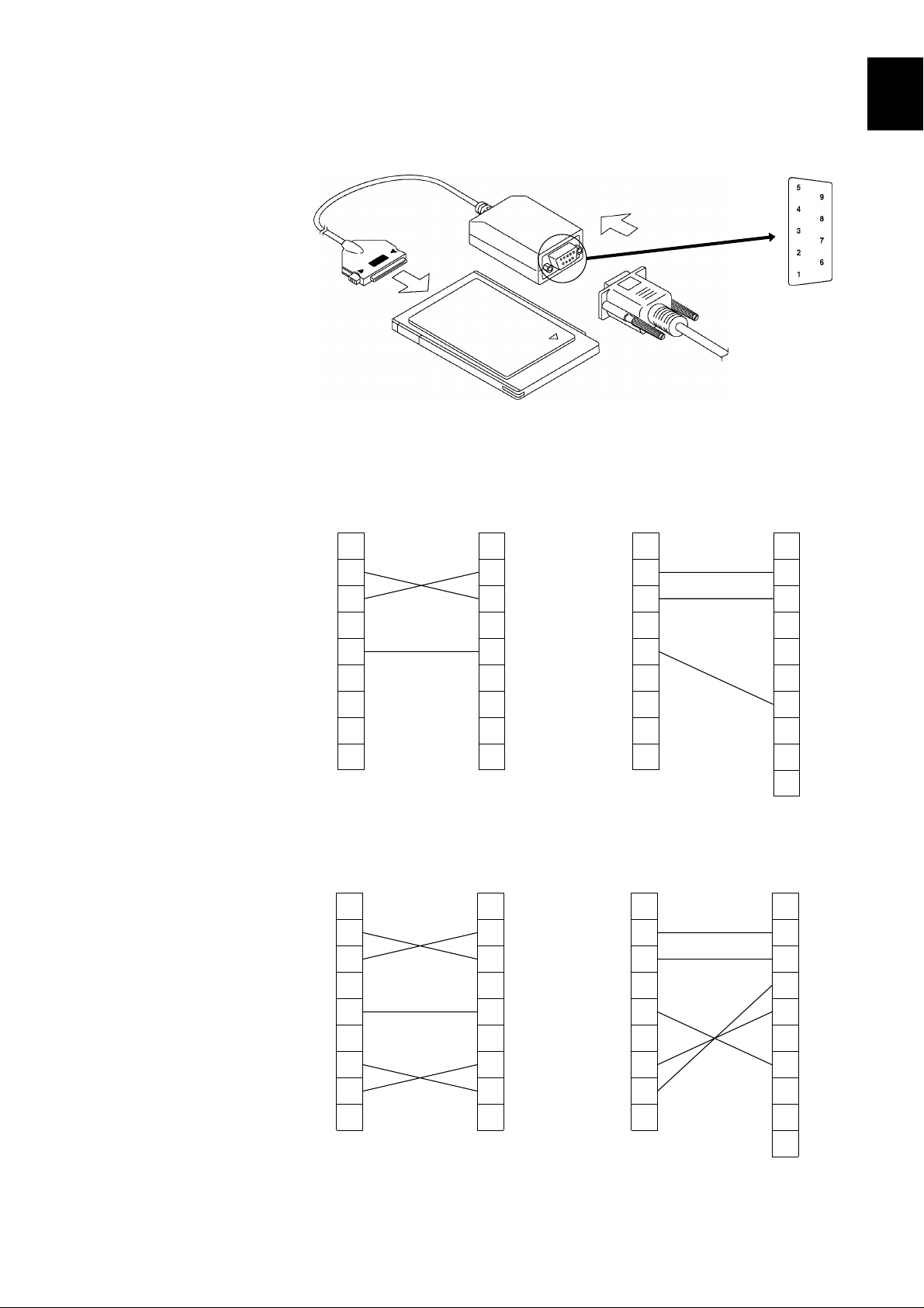
Connector Pin Assignment
The connector on the PC card is a D-sub 9-pin connector (male).
Make connection to the computer using a null-modem cable with the type of
connector that matches the computer.
OFF/Xon-Xoff flow contro
9 pin
9 pin
9 pin
25 pin
1
2
3
4
5
6
CD
1
RD
2
SD
3
ER
4
SG
5
DR
6
RS
7
CS
8
C
9
Hard flow contro
9 pin
CD
1
RD
2
SD
3
ER
4
SG
5
DR
6
RS
7
CS
8
C
9
1
2
3
4
5
6
7
8
9
9 pin
1
2
3
4
5
6
7
8
9
CD
RD
SD
ER
SG
DR
RS
CS
CD
RD
SD
ER
SG
DR
RS
CS
C
C
1
2
3
4
5
6
7
8
9
9 pin
1
2
3
4
5
6
7
8
9
1
2
3
4
5
6
7
8
2
0
2
2
25 pin
1
2
3
4
5
6
7
8
2
0
2
2
FG
SD
RD
RS
CS
DR
SG
CD
ER
CI
FG
SD
RD
RS
CS
DR
SG
CD
ER
CI
7
8
9
10
11
12
13
14
A
────────────────────────────────────────────────────
1.2 RS-232C Interface
Page 12

6
t
l
t
l
────────────────────────────────────────────────────
25 pins
Pin number
1 Protective ground 101 AA - FG
2 Transmitted data 103 BA SD TxD
3 Received data 104 BB RD RxD
4 Request to send 105 CA RS RTS
5 Clear to send 106 CB CS CTS
7 Signal ground 102 AB SG GND
Circuit designation
CCITT circui
number
EIA symbolJIS symbolCommon symbo
9 pins
Pin number
2 Received data 104 BB RD RxD
3 Transmitted data 103 BA SD TxD
5 Signal ground 102 AB SG GND
7 Request to send 105 CA RS RTS
8 Clear to send 106 CB CS CTS
Circuit designation
CCITT circui
number
EIA symbolJIS symbolCommon symbo
────────────────────────────────────────────────────
1.2 RS-232C Interface
Page 13
7
1
11121
1
N
.
)
"
,
2
n
2
────────────────────────────────────────────────────
Chapter
1
2
Method of Operatio
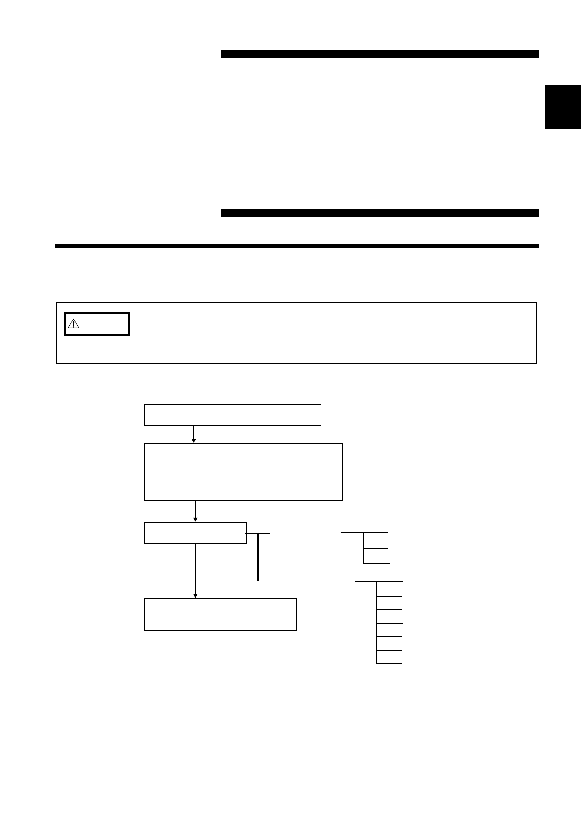
.1 Basic Operational Procedure
CAUTIO
The GP-IB or RS-232C interface is not isolated from the unit system.
Exercise caution, because the ground of the logic inputs and the GP-IB
or RS-232C interface ground are connected.
Connect GP-IB or RS-232C cable
3
4
5
6
7
8
Check that the power is ON for all
devices connected to the bus. (GP-IB
Check that the power is ON for the
unit. (RS-232C)
Set "INTERFACE.
Send orders to the controller
and perform remote control.
GP-IB set up
RS-232C set up
GP-IB mode
Address
Header
Transfer rate
Data length
Parity
Stop bits
Delimiter
Header
Flow control
9
0
3
4
A
────────────────────────────────────────────────────
2.1 Basic Operational Procedure
Page 14
8
N
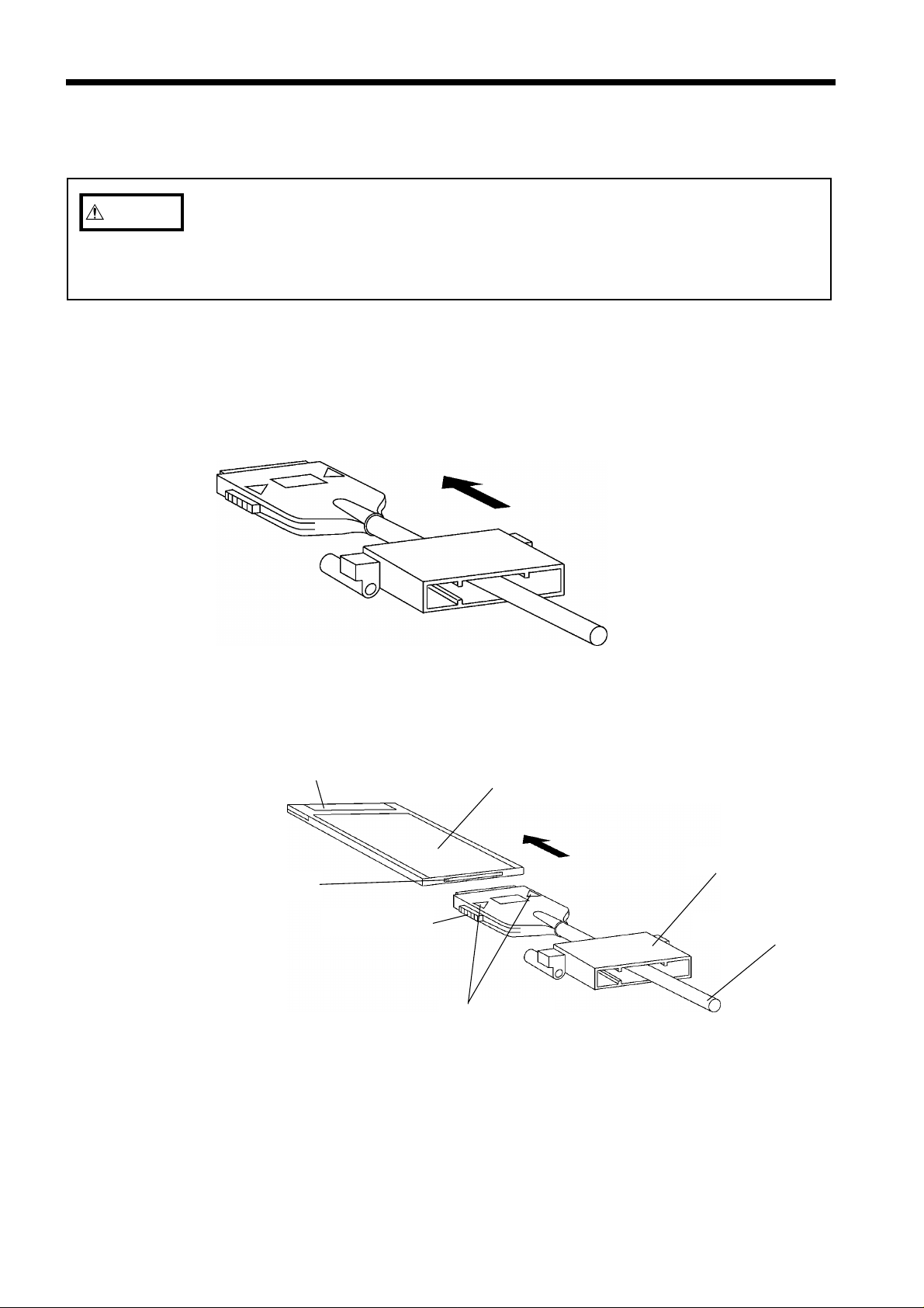
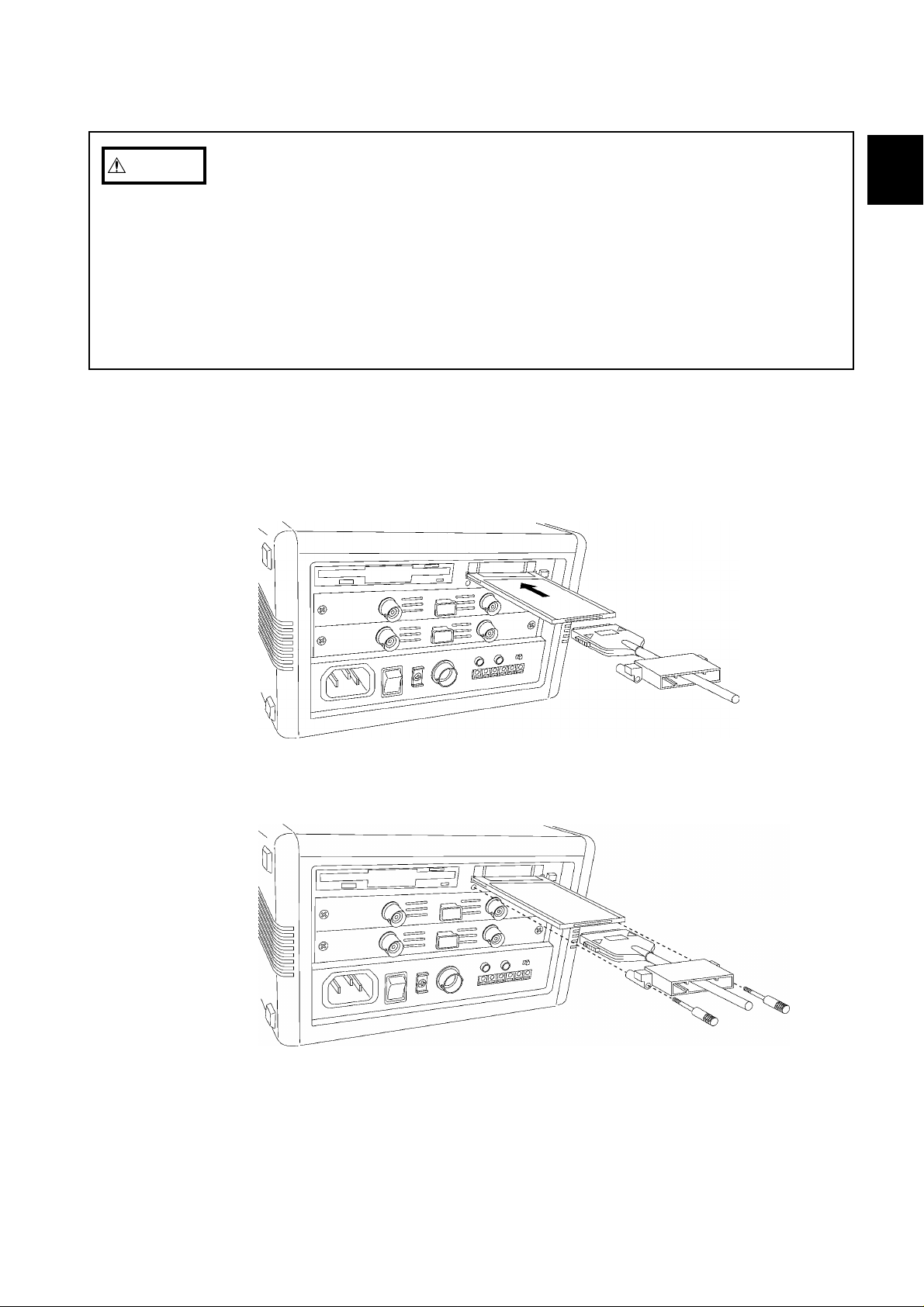
Fig. 2.1 Passing protector through connection cable
e
s
d
e
k
g
r
Fig. 2.2 Connection cable and PC card connection
2
────────────────────────────────────────────────────
.2 Cable Connection
CAUTIO
When making the connection, the cable connector and PC card should be
properly aligned, so that the connector can be pushed in straight. Do not exert
strong force on the PC card connector, to prevent the possibility of damage
and contact problems.
This section explains procedures for connecting the cable using the 8835 as an
example. For other models, refer to the instruction manual included with the
unit.
(1) Cable and PC card connection
1. Pass the PC card protector through the connection cable, as shown below.
2. Plug the PC card end of the connection cable into the PC card. The top side
of the cable connector (marked with a ▲) should match the top side of the
PC card, as shown below.
PCMCIA socket sid
Loc
Locking sprin
PC car
Protecto
Connection cabl
Front marking
────────────────────────────────────────────────────
2.2 Cable Connection
Page 15
9
1
11121
1
N
Fig. 2.3 PC card insertion
Fig. 2.4 Attaching the protector
────────────────────────────────────────────────────
CAUTIO
(2) Inserting the PC card
The following actions may result in damage to the PC card or connector and
must be avoided.
・Inserting the card with the wrong orientation or in other ways than described
above.
・Inserting the card while attached to the connection cable.
・Moving the unit while the connection cable is connected to the card.
・Pulling the card out by the cable or exerting excessive force on the
connector.
・Placing objects on the connection cable connector.
1. Insert the PC card in the PC card slot on the unit. Verify that the ▲ mark
on the card points in the correct direction as shown below, and make sure
that the card is properly seated in the slot.
The PC card is keyed to prevent wrong insertion, but exerting excessive
force may damage the card or the slot.
1
2
3
4
5
6
2. Attach the PC card protector to the unit as shown below.
7
8
9
0
3
────────────────────────────────────────────────────
2.2 Cable Connection
4
A
Page 16

10
Fig. 2.5 Removing the protector
Fig. 2.6 Removing the PC card
────────────────────────────────────────────────────
(3) Removing the PC card
1. Remove the PC card protector as shown below.
2. To remove the PC card, press the eject button as shown below.
NOTE
────────────────────────────────────────────────────
2.2 Cable Connection
Do not press the eject button before removing the PC card protector.
Page 17

11
1
11121
1
2
)
2
────────────────────────────────────────────────────
.3 Setup Procedure
1
.3.1 GP-IB Setup Procedure
・On the unit, set the GP-IB address for the unit, and select whether or not to
use headers mode, and delimiter in messages output by the unit.
・Use the interface setting screen, accessed from the "system" screen.
・This section explains procedures for setting the GP-IB using the 8835 as an
example. For other models, refer to the instruction manual included with the
unit.
Method
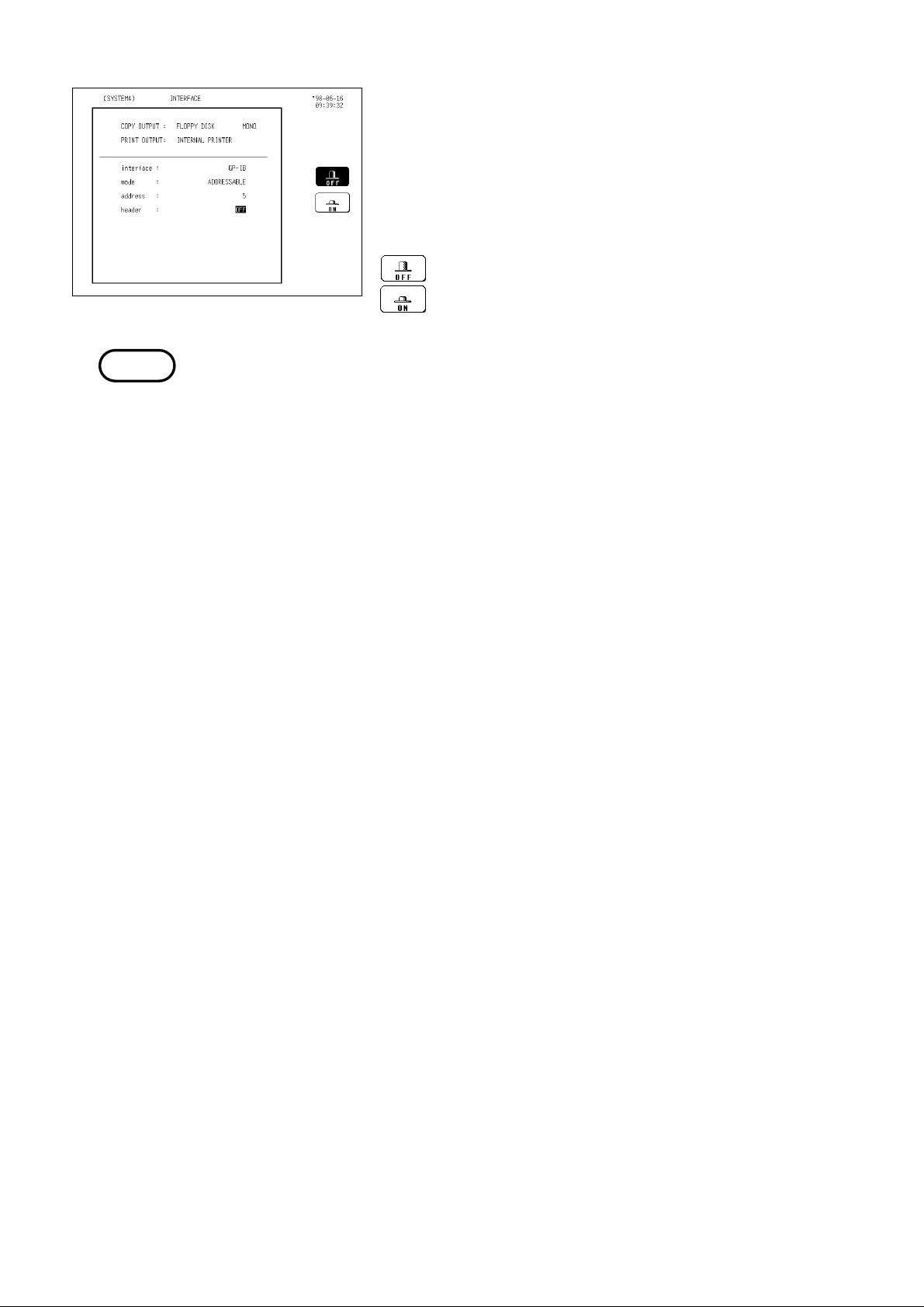
System screen (INTERFACE
2
3
4
5
1. Press the SYSTEM key to call up the interface setting
screen.
6
7
8
2. Set the GP-IB operation mode for this unit.
Set the GP-IB address for this unit on the bus.
[ADDRESSABLE, TALK ONLY, DISABLE]
Move the flashing cursor to the position shown in the
figure on the left, and use the function keys to make
the setting.
:
(ADDRESSABLE) Assign a device address, so this
unit can be used both as talker and
listener.
: (TALK ONLY) Use this unit as talker only (used
when transmitting the BMP data).
: (DISABLE) Do not use the GP-IB interface.
3. Set the GP-IB device address.
Move the flashing cursor to the position shown in the
figure on the left, and use the function keys or the jog
control to adjust the numerical value.
[0 to 30]
9
0
3
4
A
────────────────────────────────────────────────────
2.3 Setup Procedure
Page 18
12
────────────────────────────────────────────────────
4. Enable or disable the headers.
Select whether or not this unit as talker should output
an identifying header at the beginning of each
message it sends.
Move the flashing cursor to the position shown in the
figure on left, and use the function keys to make the
setting.
: Header information is not appended.
: Header information is appended.
NOTE
・The unit automatically recognizes which type of PC card is inserted, and the
appropriate setting items appear on the display. Perform the setting
procedure after inserting the GP-IB card.
・Do not change the settings during communications.
────────────────────────────────────────────────────
2.3 Setup Procedure
Page 19

13
2
)
────────────────────────────────────────────────────
.3.2 RS-232C Setup Procedure
・On the unit, make the settings for the RS-232C transfer rate, data length,
parity, stop bits, delimiter and flow control
・Use the interface setting screen, accessed from the "system" screen.
・This section explains procedures for setting the RS-232C using the 8835 as an
example. For other models, refer to the instruction manual included with the
unit.
Method
1. Press the SYSTEM key to call up the interface setting
screen.
System screen (INTERFACE
2. Set the transfer rate.
Move the flashing curson to the position shown in the
figure on the left, and use the function keys to make
the selection.
3. Set the data length.
Move the flashing curson to the position shown in the
figure on the left, and use the function keys to make
the selection.
: Sets the data length to 8 bits.
: Sets the data length to 7 bits.
4. Set the parity.
Move the flashing curson to the position shown in the
figure on the left, and use the function keys to make
the selection.
: No parity
: Even number parity
: Odd number parity
────────────────────────────────────────────────────
2.3 Setup Procedure
Page 20

14
────────────────────────────────────────────────────
5. Set the stop bits.
Move the flashing curson to the position shown in the
figure on the left, and use the function keys to make
the selection.
: Sets the stop bit to 1 bit.
: Sets the stop bit to 2 bits.
6. Set the delimiter.
Move the flashing curson to the position shown in the
figure on the left, and use the function keys to make
the selection.
: Sets the delimiter to LF.
: Sets the delimiter to CR+LF.
NOTE
7. Set the headers.
Move the flashing curson to the position shown in the
figure on the left, and use the function keys to make
the selection.
: Header information is not appended.
: Header information is appended.
8. Set the flow control.
Move the flashing curson to the position shown in the
figure on the left, and use the function keys to make
the selection.
: No flow control
: Software handshake
: Hardware handshake
・If an overrun error, a framing error or the like occurs, reduce the transfer
rate.
・The unit automatically recognizes which type of PC card is inserted, and the
appropriate setting items appear on the display. Perform the setting
procedure after inserting the RS-232C card.
・Do not change the settings during communications.
────────────────────────────────────────────────────
2.3 Setup Procedure
Page 21

15
s
s
s
2
────────────────────────────────────────────────────
.4 Receive and Send Protocols
(1) Messages
Data received or sent by the GP-IB or RS-232C interface is called a message.
The following are the message types:
Message
Program messages
Response message
Of these, program messages are those received by the unit from the controller,
while response messages are those sent from the unit to the controller.
Program messages are command messages or query messages.
Command messages are orders for control of the device, such as for making
settings or for reset or the like.
Query messages are orders for responses relating to the results of operation,
results of measurement, or the state of device settings.
Response messages are sent in response to query program messages. After a
query message has been received, a response message is produced the moment
that its syntax has been checked.
Command program message
Query program messages
(2) Command syntax
When no ambiguity would arise, the term "command" is henceforth used to
refer to both command and query program messages.
The unit accepts commands without distinction between lower case and upper
case letters.
The names of commands are as far as possible mnemonic. Furthermore, all
commands have a long form, and an abbreviated short form.
In command references in this manual, the short form is written in upper case
letters, and then this is continued in lower case letters so as to constitute the long
form. Either of these forms will be accepted during operation, but intermediate
forms will not be accepted.
Further, during operation both lower case letters and upper case letters will
be accepted without distinction.
The unit generates response messages in the long form (when headers are
enabled) and in upper case letters.
(Example)
For "DISPlay", either "DISPLAY" (the long form) or "DISP" (the short form)
will be accepted. However, any one of "DISPLA", "DISPL", or "DIS" is wrong
and will generate an error.
────────────────────────────────────────────────────
2.4 Receive and Send Protocols
Page 22

16
e
d
Data
e
a
r
e
e
a
────────────────────────────────────────────────────
(3) Command program headers
Commands must have a header, which identifies the command in question.
There are three kinds of header: the simple command type, the compound
command type, and standard command type.
Simple command type header
The first word constitute the header.
Exampl
Simple comman
type header
:HEADer ON
Compound command type header
A header made up from a plurality of simple command type headers marked
off by colons.
Exampl
:CONFigure:TDIV 1.E-3
Simple command
type header
Compound command type heade
Dat
Standard command type header
A command beginning with an asterisk and stipulated by IEEE 488.2
Exampl
*RST
(4) Query program headers
These are for commands used for interrogating the unit about the result of an
operation or about a setting.
These can be recognized as queries by a question mark appearing after the
program header. The structure of the header is identical to that of a
command program header, with "?" always being affixed to the last command.
There are queries possible in each of the three previously described types of
command form.
Exampl
:HEADER? ON
Query program
header
Dat
(5) Response messages
Response messages relating to queries are made up from header portions
(which also may be absent due to header disablement) and data portions
identical to those of program messages, and as a general rule are sent in an
identical format to the format of the program message corresponding to their
originating query.
────────────────────────────────────────────────────
2.4 Receive and Send Protocols
Page 23

17
e
5
r
e
5
r
e
r
r
r
r
1
5
2
5
────────────────────────────────────────────────────
(6) Terminators and separators
Message Terminator
A terminator is used in order to separate the transmission of one message
from another, and this terminator is not itself included in the message.
GP-IB interface
LF, EOI, or LF+EOI is used as the message terminator, and LF+EOI is also
used as the response message terminator.
RS-232C interface
Set the delimiter for the message terminator (see Section 2.3.2).
Message Unit Separator
A semicolon ";" is used as a message unit separator when it is desired to set
out several messages on a single line.
Exampl
:CONFIGURE:TDIV 1. E-3;:CONFIGURE:SHOT 1
Message unit separato
Header separator
With a message which has both a header and data, a space "_" is used as a
header separator to separate the header from the data. The space "_" is used
by way of explanation, but it does not appear on the actual program.
Exampl
:CONFIGURE:SHOT_1
Header separato
Data separator
Commas are used as data separators for separating several data items from
one another.
Exampl
Simple command type heade
Compound command type heade
:DISPLAY:DRAW CH1,DARK
Data separato
Header separato
(7) The command tree
The rule when writing several messages of compound command form on the
same line, when no colon is prefixed to the next header after the semicolon
(the message unit separator), is that that header is considered as continuing
on from the header before the last colon in the message directly preceding.
This corresponds to the general concept of the current directory in the
directory structure of UNIX or MS-DOS, and this directly preceding header is
called the "current path".
Example
Example
:CONF:TDIV 1. E-3;:CONF:SHOT 1
:CONF:TDIV 1. E-3;SHOT 1
Both Example 1 and Example 2 are messages setting TIME/DIV to 1 ms and
recording length to 15 divisions.
With Example 1, because there is a colon directly after the semicolon, the
current position is the "root". Accordingly the reference of the next command
is performed from the root.
────────────────────────────────────────────────────
2.4 Receive and Send Protocols
Page 24

18
s
t
────────────────────────────────────────────────────
On the other hand, with Example 2, because with ":CONF:TDIV 1. E-3;" the
current path has become ":CONF", it is now possible to omit the ":CONF:"
before "SHOT".
To reiterate, the colon at the beginning of a command forces the search for the
command to begin from the root. Thus in Example 1:
:CONFIGURE:TDIV 1.E-3
The first colon indicates that the "CONFIGURE" command is
at the root level.
(8) Data format
The unit uses character data, decimal data and character string data as a data
format.
Character data
The first character must be alphabetic.
The characters after the first character can only be alphabetic characters,
numerals, or underline characters (_).
As alphabetic characters, during sending only upper case letters are used,
but during receiving both upper case and lower case letters are permitted.
Decimal data
Decimal data values are represented in what is termed NR format.
There are three types of NR format from NR1 to NR3, and each of these can
appear as either a signed number or an unsigned number. Unsigned numbers
are taken as positive.
Further, if the accuracy of a numerical value exceeds the range with which the
unit can deal, it is rounded off. (5 and above is rounded up; 4 and below is
rounded down.)
NR1 format - integer data
Examples: +15, -20, 25
NR2 format - fixed point numbers
Examples: +1.23, -4.56, 7.89
NRf forma
NR3 format - floating point number
Examples: +1.0E-3, -2.3E+3
The term "NRf format" includes all these three formats.
When the unit is receiving it accepts NRf format, but when it is sending it utilizes
whichever one of the formats NR1 to NR3 is indicated in the particular command.
Character string data
Character string data is enclosed within quotation marks.
The data is composed of 8 bit ASCII characters.
Characters which cannot be handled by the unit are replaced by spaces.
When the unit is sending, only the double quotation mark (") is used as a
quotation mark, but when receiving both this double quotation mark and
also the single quotation mark (’) are accepted.
────────────────────────────────────────────────────
2.4 Receive and Send Protocols
Page 25

19
2
────────────────────────────────────────────────────
.5 The Status Byte and the Event Registers
(1) The status byte
Each bit of the status byte is a summary (logical OR) of the event register
corresponding to that bit.
Further, for GP-IB, the status byte and each event register has an enable
register corresponding to it, and according to the setting of this enable register
(which starts off at zero when the power is turned on) it is possible to mask
the service requests originating from each event.
For RS-232C, only the values for the status byte, standard event status
register, and event status register 0 are valid. The enable register setting has
no effect and is disregarded.
Status byte bit settings
bit 7 Unused: 0
bit 6
RQS
MSS
bit 5
ESB
bit 4
MAV
bit 3 Unused: 0
bit 2 Unused: 0
bit 1 Unused: 0
bit 0
ESB0
The following commands are used for reading the status byte, and for setting
the service request enable register and for reading it.
Reading the status byte *STB?
Setting the service request enable register *SRE (GP-IB)
Reading the service request enable register *SRE? (GP-IB)
Set when a service request is issued.
(For RS-232C, unused: 0)
Event summary bit.
Shows a summary of the standard event status register.
Message available.
Shows that a message is present in the output queue.
Event summary bit 0
Shows a summary of event status register 0.
────────────────────────────────────────────────────
2.5 The Status Byte and the Event Registers
Page 26

20
────────────────────────────────────────────────────
(2) Standard event status register (SESR)
The summary of this register is set in bit 5 of the status byte.
For GP-IB, each bit is masked by setting the standard event status enable
register (which starts off at zero when the power is turned on).
The circumstances when the contents of the standard event status register are
cleared are as listed below.
1. When the *CLS command is received.
2. When the contents have been read by an *ESR? query.
3. When the power is turned off and turned on again.
Bit allocations in the standard event status register
bit 7
PON
bit 6
URQ
bit 5
CME
bit 4
EXE
The power has been turned on again.
Since this register was last read, the unit has been
powered off and on.
User request: not used.
Command error.
There is an error in a command that has been received;
either an error in syntax, or an error in meaning.
Execution error.
An error has occurred while executing a command.
Range error; Mode error.
Device dependent error.
bit 3
DDE
It has been impossible to execute some command, due to
an error other than a command error, a query error, or an
execution error.
bit 2
QYE
Query error.
The queue is empty, or data loss has occurred (queue
overflow).
bit 1 Request for controller right (not used) Unused: 0
bit 0
OPC
Operation finished.
Only set for the *OPC command.
The following commands are used to read the standard event status register,
and to set or read the standard event status enable register.
Read the standard event status register *ESR?
Set the standard event status enable register *ESE (GP-IB)
Read the standard event status enable register *ESE? (GP-IB)
────────────────────────────────────────────────────
2.5 The Status Byte and the Event Registers
Page 27

21
.
────────────────────────────────────────────────────
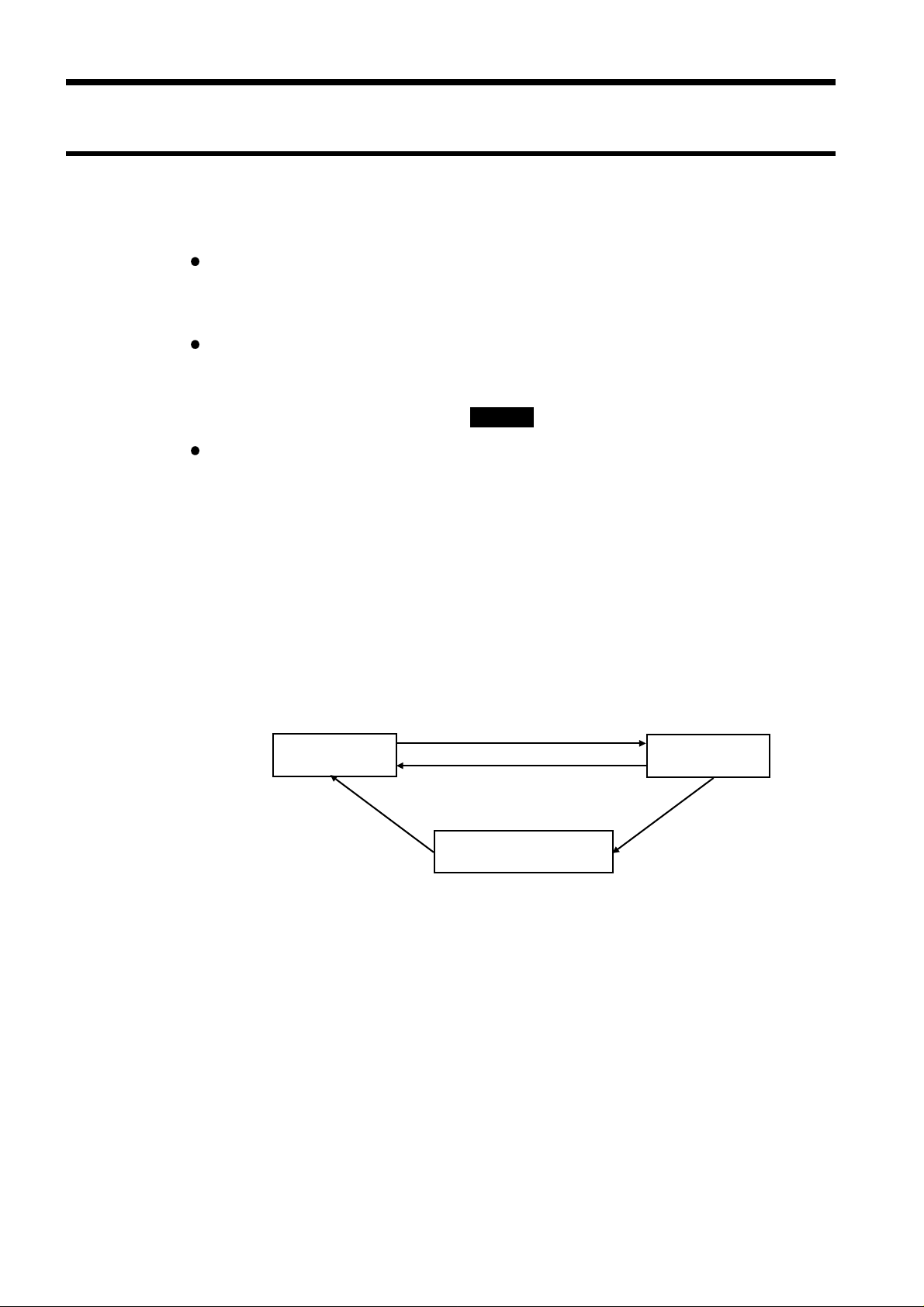
(3) Event status register 0 (ESR0)
The summary of this register is set in bit 0 of the status byte.
For GP-IB, each bit is masked when the event status enable register 0 (which
starts off at zero when the power is turned on) is set.
The circumstances when the contents of event status register 0 are cleared are
as listed below.
1. When the *CLS command is received.
2. When the contents have been read by an :ESR0? query.
3. When the power is turned off and turned on again.
The bits of event status register 0
bit 7 Waveform decision fail (NG).
bit 6 Parameter decision fail (NG).
bit 5 Parameter calculation finished.
bit 4 Waveform processing calculation finished.
bit 3 Printer operation finished (print, or copy output).
bit 2 Trigger wait finished (set when the trigger event occurs).
bit 1 Measurement operation concluded (set by STOP).
bit 0 Error not related to the GP-IB interface; printer error etc
The following commands are used for reading the event status register 0, and
for setting the event status enable register 0 and for reading it.
Reading event status register 0 :ESR0?
Setting event status enable register 0 :ESE0 (GP-IB)
Reading event status enable register 0 :ESE0? (GP-IB)
────────────────────────────────────────────────────
2.5 The Status Byte and the Event Registers
Page 28

22
Logical product
76543210
76543210
7 543210
S
S
(
)
O
e
(Read by *ESR?)
(
(
>)
.
a
a
a
a
Example: *ESE 32 (enables bit 5.)
S
er
S
er
7
321
(
?)
(
(
>)
E
.)
)
B
────────────────────────────────────────────────────
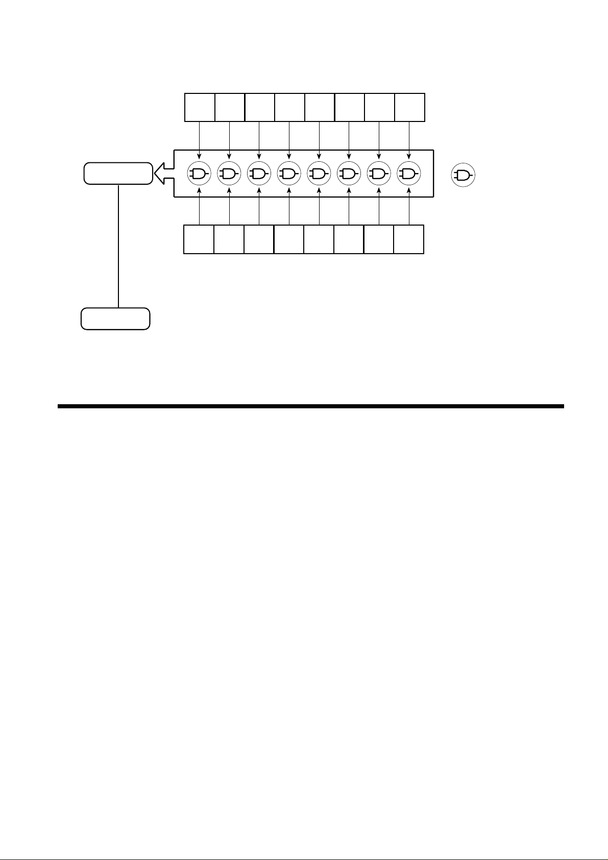
Status byte data structure
Standard event status resister
Logical sum
Read by *ESE?)
Set by *ESE<NRf
Standard event status enable register
NL(LF
Originate service
request
Logical sum
There is data in the output queue
tatus byte regist
RQ
6
ESB MAV
MS
ervice request enable regist
ES
0
Dat
Dat
Dat
Dat
utput queu
Read via serial polling
Read by *STB
Read by *SRE?)
Set by *SRE<NRf
xample: *SRE 32 (enables bit 5
────────────────────────────────────────────────────
2.5 The Status Byte and the Event Registers
Page 29
23
76543210
76543210
(Read by :ESR0?)
(
(
>)
Example: :ESE0 4 (enables bit 2.)
Summary message
E
)
(bit 0 of the status byte register)
Logical product
2
────────────────────────────────────────────────────
Event status register 0 data structure
Event status register 0
Logical sum
Read by :ESE0?)
Set by :ESE0<NRf
Event status enable register 0
ESB0
vent summary bit 0(MSB0
.6 The Input Buffer and the Output Queue
(1) Input buffer
The unit has an input buffer of 1024 bytes capacity.
Messages which are received are put into this buffer and executed in order.
However, an ABORT command is executed instantly as soon as it is received.
(2) Output queue
The unit has an output queue of 512 bytes capacity.
Response messages are accumulated in this queue and are read out from the
controller.
If the length of a response message has exceeded 512 bytes, a query error
occurs.
The circumstances when the output queue is cleared are as listed below:
1. When the controller has read out its entire contents.
2. When a device clear is issued.
3. When the power is turned off and turned on again.
4. Upon receipt of the next message.
────────────────────────────────────────────────────
2.6 The Input Buffer and the Output Queue
Page 30
24
2
t
y
2
────────────────────────────────────────────────────
.7 Others
.7.1 GP-IB
(1) Remote Control
Local state
This is the state in which the unit is controlled by its keys. When the power
is turned on, the unit always comes up in local state.
Remote state
In this state the unit is controlled from the GP-IB interface (the REN line is
"true"), and its keys are disabled. When in the remote state, the unit returns
to local state if the local key (the [LOCAL] function key) is pressed.
Local lockout state
When an LLO (Local Lockout) command (this is a GP-IB universal command)
is received, even if the local key is pressed, the unit is prevented from
returning to the local state. This state is called the local lockout state.
In order to return the unit from the local lockout state to the local state, it is
necessary either (a) to send a GTL (Go To Local) command (this is a GP-IB
universal command), or (b) to turn the power to the unit temporarily off and
then on again, or (c) to bring the line REN to "false".
If a command is sent with REN in the "false" state, then the only way to
return to the local state is with the local key.
REN "true", command sen
Local State
REN "false", GTL, local ke
REN "false", GTL
Local Lockout State
Program example HP-9816 (Hewlett-Packard)
local lockout LOCAL LOCKOUT 7
local LOCAL 7
Remote
LLO
(2) Device Clear
When the unit receives the device clear command, it clears the input buffer
and the output queue (see Section 2.6).
The device clear command is exemplified by the following:
HP 9816 (made by Hewlett-Packard)
CLEAR 7
────────────────────────────────────────────────────
2.7 Others
Page 31

25
2
────────────────────────────────────────────────────
(3) GP-IB Errors
When a command which has been received contains an error, that one of bits 2
to 5 of the standard event status register which corresponds to the event
which has occurred is set.
Further, if a command has given rise to an error (apart from an execution
error), commands accumulated in the input buffer and waiting for execution
after that command are ignored.
.7.2 RS-232C
RS-232C Errors
(1) Parity error
The parity bit can be set to even parity, odd parity, or no parity. When even or
odd is selected, the "1" count is used to detect transmission errors. If the
parity count is different at the receiving end, a parity error is returned.
(2) Framing error
When counting from the start bit, if the stop bit is "L", a framing error is
returned.
Possible reason (1): Transmission rate, parity, stop bit or other parameter
setting mismatch
Possible reason (2): Noise
(3) Overrun error
The transmission controller uses double buffering for receiving data (shift
buffer for each bit and reception buffer read by the CPU).
When there are data in the reception buffer, and the shift register completes
reception of the next character before the data are read by the CPU, an
overrun error occurs. Because the new data overwrites the previous data in
the reception buffer, immediately preceding data are lost.
Possible reason (1): Transmission rate is too high.
Possible reason (2): Some interrupt inhibit intervals are too long.
Possible reason (3): Execution time for higher-priority interrupt is too long,
reducing the time available for the receive interrupt.
────────────────────────────────────────────────────
2.7 Others
Page 32

26
────────────────────────────────────────────────────
Flow Control
The RS-232C interface can transfer data at the selected transfer rate, but if
the CPU cannot keep up with the data that are being sent, later data will
overwrite data that were received earlier. To prevent this, the receiving side
must alert the sending side when the reception buffer is about to become full,
so that the transfer can be temporarily paused. This is called flow control. Two
types of flow control are possible, namely hardware handshaking and software
handshaking.
(1) Hardware handshaking
Flow control is performed by setting the signal lines RTS (RS) and CTS (CS)
to ON and OFF.
Receiving data
When input buffer content exceeds 3/4, RTS is set to Low.
When input buffer content falls below 1/4, RTS is set to High.
Sending data
When CTS becomes Low, data send is interrupted.
When CTS becomes High, data send is resumed.
(2) Software handshaking
Flow control is performed using the Xon and Xoff code.
Receiving data
When input buffer content exceeds 3/4, D3 (13H) is sent.
When input buffer content falls below 1/4, D1 (11H) is sent.
Sending data
When D3 (13H) is received, data send is interrupted.
When D1 (11H) is received, data send is resumed.
Note: Buffer size is as follows.
Input buffer: 1024 bytes
Output buffer: 512 bytes
────────────────────────────────────────────────────
2.7 Others
Page 33

27
1
11121
1
3
3
s
3
────────────────────────────────────────────────────
Chapter
1
2
Command
When using the HIOKI MEMORY HiCORDER can be used with the HIOKI
"9557 RS-232C CARD / 9558 GP-IB CARD" except following products, reffer to
the communication comands manual (Flopply disk) supplied with the
MEMORY HiCORDER.
■ The products consultable this manual: 8826, 8835, 8835-01, 8841, 8842
.1 Command Summary
.1.1 Standard Commands Specified by IEEE 488.2
Command
(for a query, response data)
Data
Explanation
Ref
page
35
26
41
42
20
3
4
5
6
7
8
9
*IDN? Maker’s name, model number,
serial number, software
version (not used, zero)
*OPT? Whether channel 1 to 4 input
units exist (8835)
Whether channel 1 to 32 input
units exist (8826)
Whether channel 1 to 16 input
units exist (8841, 8842, 8720)
0: none, 1: analog, 2: voltage/
temperature, 3: strain, 4: FFT,
5: F/V, 6: charge, 7: 4-channel
unit
*RST Device initial setting. 60 Y Y Y
*TST? A <NR1>
(0 = normal, 1 = failure)
*OPC Sets the LSB of SESR after all action
*OPC? A <NR1> ASCII 1 is the response after all
*WAI Executes the following command after
*CLS Clears the status byte and associated
Queries device ID.
Queries device option provision.
Queries the result of the ROM/RAM
check.
has been completed.
action has been completed.
action has been completed.
queues.
59 Y Y Y
59 Y Y Y
60 Y Y Y
60 Y Y Y
61 Y Y Y
61 Y Y Y
61 Y Y Y
0
3
4
A
────────────────────────────────────────────────────
3.1 Command Summary
Page 34

28
3
1
────────────────────────────────────────────────────
Command
*ESE A A: 0 to 255 Sets SESER. (GP-IB only)
*ESE? A <NR1> 0 to 255 Queries SESER
*ESR? A <NR1> 0 to 255 Queries SESR. 62 Y Y Y
*SRE A A: 0 to 255 Sets SRER. (GP-IB only)
*SRE? A <NR1> 0 to 63, 128 to 191 Queries SRER.
*STB? A <NR1> 0 to 255 Reads the STB and the MSS bit,
:ESE0 A A: 0 to 255 Sets ESER0. (GP-IB only)
:ESE0? A <NR1> 0 to 255 Queries ESER0.
:ESR0? A <NR1> 0 to 255 Queries ESR0. 64 Y Y Y
(for a query, response data)
Data
Explanation
without performing serial polling.
Note 35: 8835 (-01), 26: 8826, 41: 8841, 42: 8842
20: 8720, Y: Yes, A: Advanced version
Ref
3526414220
page
62 Y Y Y
63 Y Y Y
63 Y Y Y
64 Y Y Y
.1.2 Specific Commands
Execution control etc. (common to all functions)
Command
:STARt Same as the START key. 65 Y Y Y
:STOP Same as the STOP key. 65 Y Y Y
:ABORT Forced halt. 65 Y Y Y
:PRINt Same as the PRINT key. 65 Y Y N
:HCOPy Same as the COPY key. 65 Y Y N
:FEED A A: 1 to 255 (unit mm) Feeds the paper the specified distance.66 Y Y N
:REPOrt Same as the FEED key + COPY key. 66 Y Y N
:AUTO Sets the time axis and the voltage
:ERRor? A <NR1> error number Queries 8835 error number. 66 Y Y Y
:HEADer A$ A$: OFF, ON Enables and disables headers.
:HEADer? A$ Queries headers.
:FUNCtion A$ A$: MEM, REC, RMS, R_M,
:FUNCtion? A$ Queries the function.
(for a query, response data)
FFT
Data
Explanation
axis automatically. (Only the memory
recorder function)
Changes the function.
Ref
3526414220
page
66 Y Y N
67 Y Y Y
67 Y Y N
:CERRor? A, B, C: number of times
A: parity error
B: overrun error
C: framing error
:STATus? A <NR1> 0 to 127 Queries the status.
────────────────────────────────────────────────────
3.1 Command Summary
Queries the communication errors.
(RS-232C only)
Note 35: 8835 (-01), 26: 8826, 41: 8841, 42: 8842, 20: 8720
Y: Yes, A: Advanced version, *: 8835-01 only
67 Y Y Y
*
66
Y N
Page 35

29
1
11121
1
2
:CONFigure
-
.
────────────────────────────────────────────────────
CONFigure command (Setting and querying the time axis range, the recording length, etc.)
Command
:TDIV A A: TIME/DIV (unit seconds)
:TDIV? A <NR3> (unit seconds) Queries the time axis range.
:TDIV A, B A: TIME/DIV for REC,
:TDIV? A, B <NR3> (unit seconds) Queries the time axis ranges.
:SAMPle A A: sampling rate (unit
:SAMPle? A <NR3> Queries the sampling period.
(for a query, response data)
100 μs to 5 min/DIV
(MEM)
(0: external sampling
(except 8835))
10 ms to 1 h/DIV (REC)
(8835)
20 ms to 1 h/DIV (REC)
(8826, 8841, 8842)
5 s to 1 h/DIV (RMS)
B: TIME/DIV for MEM
seconds)
1 μs to 100 ms
Data
Explanation
Sets the time axis range.
Sets the time axis ranges.
Sets the sampling period.
Func
tion
MEM
REC
RMS
R&M 68 A Y N
REC 69 Y Y N
Ref
3526414220
page
68 Y Y N
1
2
3
4
5
6
7
:SAMPle A$ A: FAST, SLOW Sets the sampling speed.
:SAMPle? A$ Queries the sampling speed.
:FREQuency A A: 50, 60 (Hz) Sets the frequency.
:FREQuency? A <NR1> Queries the frequency.
:SHOT A A: recording length (unit
DIV)
1 to 20000: 8835 (MEM)
1 to 40000: 8835-01
1 to 160000: 8826, 8841,
8842
1 to CONT: (REC, RMS)
:SHOT? A <NR1> (unit DIV) Queries the recording length. Y Y N
:SHOT A, B A: REC recording length
B: MEM recording length
:SHOT? A, B <NR1> (unit DIV) Queries the recording lengths.
:RECTime A A: Recording time (unit s)
0 (continuous), 1 to 35999999
:RECTime? A <NR1> (unit s) Queries the recording time.
:RECSpeed A A: Recording speed (unit s)
0.002 to 180 (unit s)
:RECSpeed? A <NR3> (unit s) Queries the recording speed.
Sets the recording length
(during memory segmentation)
Sets the recording lengths.
Sets the recording time.
Sets the recording speed.
REC 69 N N Y
RMS 69 Y Y N
MEM
REC
RMS
R&M 70 A Y N
REC 71 N N Y
REC 71 N N Y
Y Y N
70
8
9
0
3
4
────────────────────────────────────────────────────
3.1 Command Summary
A
Page 36

30
)
,
,
,
.
.
────────────────────────────────────────────────────
:FORMat A$ A$: SINGle, DUAL,QUAD,
XYDot, XYLine (MEM, REC
SINGle, DUAL, QUAD
(RMS, R&M)
SINGle, DUAL,
NYQuist (FFT)
(8826)
A$: SINGle, DUAL, QUAD, OCT
HEX, XYSingle, XYQuad
(MEM, REC)
SINGle, DUAL, QUAD,
OCT,HEX (RMS, R&M)
SINGle, DUAL,
NYQuist (FFT)
(8841, 8842)
A$: SINGle, DUAL, QUAD, OCT
HEX, XYSingle, XYDual
(MEM, REC)
SINGle, DUAL, QUAD,
OCT,HEX (RMS, R&M)
SINGle, DUAL,
NYQuist (FFT)
A$: SINGle, DUAL, QUAD, OCT
XYSingle, XYDual
Sets the format.
Y N N
All 72
N Y N
N N Y
:FORMat? A$ Queries the format. Y Y Y
:DOTLine A$ A$: DOT, LINE (8835: FFT
only)
:DOTLine? A$ Queries the interpolation
:PRKInd A$ A$: WAVE, LOGGing Specifies the printer output
:PRKInd? A$ Queries the printer output
:SMOOth A$ A$: OFF, ON Enables and disables smooth
:SMOOth? A$ Queries smooth printing
:LOGGing A A: 0.01 to 100 Specifies the logging output
:LOGGing? A <NR2> Queries the logging output
:ROLL A$ A$: OFF, ON Enables and disables roll
Sets the interpolation function
function.
style.
style
printing.
enablement.
interval.
interval.
mode.
All 72 A Y Y
All 73 Y Y N
MEM
R&M
All 73 Y Y N
MEM 74 Y Y N
73 Y Y N
:ROLL? A$ Queries roll mode enablement.
:ATPRint A$
(,B$)
:ATPRint? A$ (,B$) Queries auto print enablement
A$: OFF, ON, LAN
B$: MONO, COLOR
Enables and disables auto
print.
MEM 74 Y Y N
────────────────────────────────────────────────────
3.1 Command Summary
Page 37

31
1
11121
1
,
,
.
.
────────────────────────────────────────────────────
:ATSAve A$,
B$ (, C$)
:ATSAve? A$, B$, (, C$) Queries auto save.
:ATFIle
’NAME$’
:ATFIle? ’NAME$’ Queries the file name for auto
:DELSave A$ A$: DEL, NORMal Sets the delete save function.
:DELSave? A$ Queries the delete save
:THINout A$ A$: OFF, 1_2 to 1_1000 Sets the degree of thinning
:THINout? A$ Queries the degree of thinning
:OVERlay A$ A$: OFF, ON Sets waveform overlay.
:OVERlay? A$ Queries waveform overlay.
A$:OFF,FD,PC,LAN
(8835)
OFF,FD,PC,SCSI,MO
LAN (8826, 8841, 8842)
B$:Bin,Text
C$:MEM,REC,R_M(R&M
only)
NAME$: file name (8
characters)
Sets auto save.
Sets the file name for auto
save function.
save function.
function.
before storing.
before storing.
All 75 Y Y Y
All 75 * Y Y
All 76 * Y Y
All 76 N N Y
MEM 76 Y Y N
1
2
3
4
5
6
7
:AVERage A A: 0, 2, 4, 8, 16, 32, 64, 128
256 (0: OFF)
:AVERage? A <NR1> Queries the count for
:WVCOmp A$ A$: OFF, OUT, ALLOut Sets the waveform decision
:WVCOmp? A$ Queries the waveform decision
:CMPStop A$ A$: GO, NG, G-N Sets the waveform decision
:CMPStop? A$ Queries the waveform decision
:VIRTual A$ A$: OFF, ON Enables and disables the
:VIRTual? A$ Queries the additional
:PRINt A$ A$: OFF, ON Sets printer output. REC
:PRINt? A$ Queries printer output.
:EXTSample A A: 10 to 1000 Sets data number per 1 DIV
:EXTSample? A <NR1> Queries data number per 1
Sets the count for averaging.
averaging.
mode.
mode.
stop mode.
stop mode.
additional recording function.
recording function enablement
for external sampling.
DIV for external sampling.
MEM 77 A Y N
MEM
FFT
MEM
FFT
REC
RMS
R&M
RMS
R&M
MEM 78 * Y N
77 A Y N
77 A Y N
78 Y Y Y
78 Y Y N
8
9
0
3
4
:MEMDiv A$ A$: OFF, SEQ, MULTI
(MULTI: MEM only)
:MEMDiv? A$ Queries memory segmentation
────────────────────────────────────────────────────
Sets memory segmentation.
MEM
R&M
3.1 Command Summary
79 A Y N
A
Page 38

32
)
)
────────────────────────────────────────────────────
:USEBlock A A: 1 to number of
segmentations (255 max.
:USEBlock? A <NR1> Queries the memory block
:STTBlock A A: 1 to number of blocks Sets the start block (during
:STTBlock? A <NR1> Queries the start block.
:ENDBlock A A: 1 to number of blocks Sets the end block (during
:ENDBlock? A <NR1> Queries the end block.
:SEQDisp A$ A$: OFF, ON Sets the follow-up waveform
:SEQDisp? A$ Queries the follow-up
:MAXBlock A A: 3, 7, 15, 31, 63, 127, 255 Sets the number of memory
:MAXBlock? A <NR1> Queries the number of memory
:REFBlock A A: 0, 1 to number of
memory segmentations
(0: OFF)(8835(-01) only)
A: 0 (OFF), 1 (ON)
(except 8835(-01))
Sets the memory block used.
used.
sequential save).
sequential save).
display (during sequential
save).
waveform display.
blocks (during multi-block).
blocks.
Sets the reference block.
MEM
R&M
MEM
R&M
MEM
R&M
MEM 80 A Y N
MEM 81 A Y N
MEM 81 A Y N
79 A Y N
80 A Y N
80 A Y N
:REFBlock? A <NR1> Queries the reference block.
:REFBlock A,
B$
:REFBlock? A A <NR1>, B$ Queries the reference block.
:FFTAVERageAA: 2, 4, 8, 16, 32, 64, 128,
:FFTAVERage? A <NR1> Queries the current setting of
:FFTAVKind A$ A$: OFF, T_EXP, F_EXP,
:FFTAVKind? A$ Queries the currently set
:FFTMode A,
ch1$, (,ch2$)
:FFTMode? A <NR1>, ch1$, ch2$ Queries the current FFT
A: 1 to number of memory
segmentations
B$: ON, OFF
256, 512, 1024, 2048,
4096
T_LIN, F_LIN, F_PEAK
A:1,2
ch1$, ch2$: CH1 to CH32
(8835: CH1 to CH4
Sets the reference block
(during multi-block).
Sets the count for averaging in
the FFT function.
the count for averaging in the
FFT function.
Sets the averaging method.
averaging method.
Sets the FFT channel mode.
channel mode.
MEM 81 N Y N
FFT 82 A Y N
FFT 82 A Y N
FFT 83 A Y N
:FFTWind A$
(,B)
:FFTWind? A$, B <NR1> Queries the current window
────────────────────────────────────────────────────
3.1 Command Summary
A$: RECTan, HANNing,
EXPOnential
B: 0 to 99 (%)
Sets the window function.
FFT 83 A Y N
function.
Page 39

33
,
────────────────────────────────────────────────────
:FFTFunction
A$, B$
:FFTFunction?A$A$, B$ Queries the current FFT
:FFTRef A$ A$: NEW, MEM Designates the source for FFT
:FFTRef? A$ Queries the current FFT
:FFTSCale A$,B$A$: G1, G2
:FFTSCale? A$ A$, B$ Queries the current display
:FFTUp A$, B A$: G1, G2
:FFTUp? A$ A$, B <NR3> Quer ies the current vertical axis
:FFTLow A$, B A$: G1, G2
:FFTLow? A$ A$, B <NR3> Quer ies the current vertical axis
A$: G1, G2
B$: STR, LIN, RMS, PSP,
ACR, HIS, TRF, CSP,
CCR, IMP, COH, OCT
B$: AUTO, MANUal
B: -9.9999E+29 to
+9.9999E+29
B: -9.9999E+29 to
+9.9999E+29
Sets the FFT analysis mode.
analysis mode.
analysis data.
analysis data source.
Sets the display scaling
method for a graph.
scaling method for a graph.
Sets the vertical axis upper
limit for a graph.
upper limit for a graph.
Sets the vertical axis lower
limit for a graph.
lower limit for a graph.
FFT 84 A Y N
FFT 85 A Y N
FFT 85 A Y N
FFT 86 A Y N
FFT 86 A Y N
:FFTXaxis A$,B$A$: G1, G2
B$: 1_1oct, 1_3oct (octave
analysis)
LINhz, LOGhz
(otherwise)
:FFTXaxis? A$ A$, B$ Queries the current x-axis
:FFTYaxis A$,B$A$: G1, G2
B$: LINMAg, LINREal,
LINIMag, LOGMAg,
PHASE
:FFTYaxis? A$ A$, B$ Queries the current y-axis
:FREQ A A: 400000, 200000, 80000,
40000, 20000, 8000,
4000, 2000, 800, 400,
200, 80, 40, 20, 8, 4, 1.33
0.667, 0.333, 0.133, 0
:FREQ? A <NR3> Queries the currently set
:OCTFilter A$ A$: NORMal, SHARp Sets the type of octave filter.
:OCTFilter? A$ Queries the currently set type
Sets the x-axis.
setting.
Sets the y-axis.
setting.
Sets the frequency range.
frequency range.
of octave filter.
FFT 87 A Y N
FFT 87 A Y N
FFT 89 A Y N
FFT 89 A Y N
:PEAK A$ A$: OFF, PEAK, MAX Sets the peak value display.
:PEAK? A$ Queries the currently set peak
value display.
────────────────────────────────────────────────────
FFT 89 A Y N
3.1 Command Summary
Page 40

34
.
e
.
3
:TRIGger
-
r
────────────────────────────────────────────────────
:FFTSAmple A A: 1000, 2000, 5000, 10000 Sets the number of FFT points
:FFTSAmple? A <NR1> Queries the number of FFT
FFT 90 A Y N
points.
:RTSAve A$ A$: ON, OFF Sets the real time save
function.
R&M 90 N Y N
:RTSAve? A$ Queries the real time save
function.
:CMPOld A$ A$: ON, OFF Sets comparison of separate
files.
All 90 N N Y
:CMPOld? A$ Queries comparison of separat
files.
:OTSAve A$ A$:FD,PC,MO,SCSI,LAN Sets one-touch save setting.
:OTSAve? A$ Queries one-touch save setting
Note 35: 8835 (-01), 26: 8826,
MEM: memory recorder function REC: recorder function
RMS: RMS recorder function R&M: recorder and memory function
FFT: FFT function
All: all MEM, REC, RMS, R&M and FFT functions
TRIGger command (Setting and querying trigger.)
Command
(for a query, response data)
:MODE A$ A$: SINGle, REPEat, AUTO
(MEM, FFT)
SINGle, REPEat (REC,
RMS)
SINGle, REPEat,
TIMEr (R&M)
Data
Explanation
Sets trigger mode.
All 91 N N Y
41: 8841, 42: 8842
20: 8720
Y: Yes
A: Advanced version
*: 8835-01 only
Func
tion
Ref
page
35
26
41
42
All 91 Y Y Y
20
:MODE? A$ Queries trigger mode.
:PRETrig A A: 0, 2, 10, ... 90, 95, 100,
-95% (MEM, R&M, FFT)
0, 5, 10 DIV (RMS, 8720)
:PRETrig? A <NR1> (unit %) Queries pre-trigger.
:TIMIng A$ A$: START, STOP, S
S
−
Sets pre-trigger.
Sets trigger timing.
MEM
RMS
R&M
92 Y Y Y
FFT
REC 92 Y Y N
:TIMIng? A$ Queries trigger timing.
:SOURce A$ A$: OR, AND Sets trigger logical operator to
AND or OR.
:SOURce? A$ Queries trigger logical operato
(AND or OR).
:MANU A$ A$: OFF, ON Sets manual trigger.
:MANU? A$ Queries manual trigger.
────────────────────────────────────────────────────
3.1 Command Summary
All 92 Y Y Y
All 93 Y Y N
Page 41

35
-
,
)
f
────────────────────────────────────────────────────
Command
(for a query, response data)
:KIND ch$, A$ A$: OFF, LEVEl, IN, OUT,
Data
Explanation
Sets type of trigger.
DROP,PERIod (MEM,
R&M, FFT)
OFF, LEVEl, IN, OUT,
PERIod (REC)
OFF, RMS (RMS)
:KIND? ch$ ch$, A$ Queries type of trigger.
:LEVEl ch$, A A: trigger level (unit V) Sets the trigger level of the
level trigger.
:LEVEl? ch$ ch$, A <NR3> Queries the trigger level of the
level trigger.
:SLOPe ch$,
A$
A$: UP, DOWN Sets the trigger direction
(slope) (level trigger, period
trigger).
:SLOPe? ch$ ch$, A$ Queries the trigger direction
(slope).
:FILTer ch$, A A: 0 (OFF), 0.1, 0.2, 0.5, 1.0
Sets trigger filter.
1.5, 2.0, 2.5, 5.0, 10.0
(DIV) (MEM, R&M, FFT
0 (OFF), 1 (ON) (REC)
:FILTer? ch$ ch$, A <NR2> Queries trigger filter.
Func
tion
Ref
page
3526414220
All 93 Y Y Y
MEM
REC
R&M
93 Y Y Y
FFT
MEM
REC
R&M
94 Y Y Y
FFT
MEM
REC
R&M
94 Y Y Y
FFT
:UPPEr ch$, A A: upper limit level (unit V) Sets upper limit level of
window-in/-out trigger.
:UPPEr? ch$ ch$, A <NR3> Queries upper limit level of
window-in/-out trigger.
:LOWEr ch$, A A: lower limit level (unit V) Sets lower limit level of
window-in/-out trigger.
:LOWEr? ch$ ch$, A <NR3> Queries lower limit level of
window-in/-out trigger.
:VFREq ch$, A A: 50/60 (Hz) Sets measurement frequency o
voltage drop trigger.
:VFREq? ch$ ch$, A <NR1> Queries measurement
frequency of voltage drop
trigger.
:VLEVel ch$, A A: drop level (V) Sets drop level of voltage drop
trigger.
:VLEVel? ch$ Queries drop level of voltage
drop trigger.
:PUPPer ch$, A A: upper limit level (s) Sets upper period limit of
period trigger.
:PUPPer? ch$ ch$, A <NR3> Queries upper period limit of
period trigger.
MEM
REC
R&M
FFT
MEM
REC
R&M
FFT
MEM
R&M
FFT
MEM
R&M
FFT
MEM
REC
R&M
FFT
95 Y Y Y
95 Y Y Y
96 Y Y N
96 Y Y N
97 Y Y N
:PLOWer ch$,AA: lower limit level (s) Sets lower period limit of
period trigger.
:PLOWer? ch$ ch$, A <NR3> Queries lower period limit of
period trigger.
────────────────────────────────────────────────────
MEM
REC
R&M
97 Y Y N
FFT
3.1 Command Summary
Page 42

36
-
,
.
────────────────────────────────────────────────────
Command
(for a query, response data)
Data
Explanation
:PLEVel ch$, A A: trigger level (V) Sets the trigger level of period
trigger.
:PLEVel? ch$ ch$, A <NR3> Queries the trigger level of
period trigger.
:RLEVel ch$, A A: trigger level (V) Sets the trigger level of RMS
level trigger.
:RLEVel? ch$ ch$, A <NR3> Queries the trigger level of
RMS level trigger.
:RSLOpe ch$,AA$: UP, DOWN Sets the direction (slope) of
RMS level trigger.
:RSLOpe? ch$ ch$, A$ Queries the direction (slope) of
RMS level trigger.
:LOGAnd ch$,A$A$: OFF, OR, AND Sets AND/OR for the logic
trigger pattern.
:LOGAnd? ch$ ch$, A$ Queries AND/OR for the logic
trigger pattern.
:LFILter ch$, A A: 0 (OFF), 0.1, 0.2, 0.5, 1.0
Sets logic trigger filter.
1.5, 2.0, 2.5, 5.0, 10.0
(DIV) (MEM)
0 (OFF), 1 (ON) (REC,
RMS)
:LFILter? ch$ ch$, A <NR2> Queries logic trigger filter.
Func
tion
Ref
page
3526414220
MEM
REC
R&M
97 Y Y N
FFT
RMS 98 Y Y N
RMS 98 Y Y N
MEM
REC
RMS
99 Y Y N
R&M
MEM
REC
RMS
99 Y Y N
R&M
:LOGPat ch$,
’A$’
:LOGPat? ch$ ch$, "A$" Queries the pattern for a logic
A$: xxxx trigger pattern (x,
0, 1)
Sets the pattern for a logic
trigger.
trigger.
MEM
REC
RMS
R&M
:TIMEr A$ A$: OFF, ON Sets timer trigger. MEM
:TIMEr? A$ Queries timer trigger.
REC
RMS
FFT
:TMSTArt
month, day,
hour, min
:TMSTArt? month, day, hour, min all
:TMSTOp
month: 1 to 12
day: 1 to 31
Sets start time of timer
trigger.
hour: 0 to 23
min: 0 to 59
Queries start time of timer
<NR1>
trigger.
Same as :TMSTArt Sets stop time of timer trigger
All 101 Y Y N
month, day,
hour, min
All 101 Y Y N
:TMSTOp? Same as :TMSTArt? Queries stop time of timer
trigger.
:TMINTvl day,
hour, min, sec
day: 0 to 99
hour: 0 to 23
Sets time interval for timer
trigger.
min: 0 to 59
sec: 0 to 59
All 102 Y Y N
100 Y Y N
100 Y Y N
:TMINTvl? day, hour, min, sec all
<NR1>
Queries time interval for timer
trigger.
────────────────────────────────────────────────────
3.1 Command Summary
Page 43

37
-
────────────────────────────────────────────────────
Command
:DETECTTime
hour, min, sec
(for a query, response data)
hour: 0 to 23
min: 0 to 59
Data
Explanation
Sets the time point for trigger
detection.
sec: 0 to 59
:DETECTTime? hour, min, sec all <NR1> Queries the currently set time
point for trigger detection.
:DETECTDate
year, month,
day
year: 0 to 99
month: 1 to 12
day: 1 to 31
Sets the date for trigger
detection.
:DETECTDate? year, month, day all <NR1> Queries the currently set date
for trigger detection.
:STOPTime
hour, min, sec
hour: 0 to 23
min: 0 to 59
Sets the termination time of
operation.
sec: 0 to 59
:STOPTime? hour, min, sec all <NR1> Queries the termination time
of operation.
:STOPDate
year, month,
day
year: 0 to 99
month: 1 to 12
day: 1 to 31
Sets the date of termination.
:STOPDate? year, month, day all <NR1> Queries the date of
termination.
Func
tion
Ref
page
3526414220
All 102 Y Y Y
All 103 Y Y Y
REC
R&M
REC
R&M
103 Y Y Y
104 Y Y Y
:EXTErnal A$ A$: OFF, ON Enables and disables external
trigger.
:EXTErnal? A$ Queries external trigger
enablement.
Note 35: 8835 (-01), 26: 8826,
All 104 Y Y Y
41: 8841, 42: 8842
20: 8720
Y: Yes
A: Advanced version
────────────────────────────────────────────────────
3.1 Command Summary
Page 44

38
4
:UNIT
-
,
s
,
/
────────────────────────────────────────────────────
UNIT command (Setting and querying input channel)
Command
(for a query, response data)
:RANGe ch$, A A: voltage axis range(V, με
℃)
Data
Explanation
Sets input channel voltage axi
range.
:RANGe? ch$ ch$, A <NR3> Queries input channel voltage
axis range.
:COUPling ch$
A$: GND, DC, AC Sets input channel coupling.
A$
:COUPling? ch$ch$, A$ Queries input channel
coupling.
:POSItion ch$,AA: position value (unit %) Sets the origin position for an
input channel.
:POSItion? ch$ ch$, A <NR1> Queries the origin position for
an input channel.
:FILTer ch$, A A: 0 (OFF), 5, 500, 5000,
Sets input channel filter.
100000
0 (OFF), 5, 500 (when
measuring temperature
with the 8937)
0 (OFF), 10, 30, 300,
3000 (8939)
Func
tion
Ref
page
3526414220
All 105 Y Y Y
All 105 Y Y Y
All 106 Y Y Y
All 106 Y Y Y
:FILTer? ch$ ch$, A$ Queries input channel filter.
:SENSor ch$,A$A$:K,E,J,T,N,R,S,B,
OFF (voltage)
Sets the type of the voltage/
temperature unit sensor.
:SENSor? ch$ ch$, A$ Queries the type of the voltage
temperature unit sensor.
:RJC ch$, A$ A$: INT, EXT Sets reference contact
compensation of the voltage/
temperature unit.
:RJC? ch$ ch$, A$ Queries reference contact
compensation of the voltage/
temperature unit.
:DRIFt ch$, A$ A$: OFF, ON Sets drift compensation of the
voltage/temperature unit.
:DRIFt? ch$ ch$, A$ Queries drift compensation of
the voltage/temperature unit.
:DFILter ch$,
A$
A$: OFF, ON Sets digital filter of the
voltage/temperature unit.
:DFILter? ch$ ch$, A$ Queries digital filter of the
voltage/temperature unit.
:AAFilter ch$,A$A$: OFF, ON Turns on or off the FFT
anti-aliasing filter.
:AAFilter? ch$ ch$, A$ Queries the current on or off
state of the FFT anti-aliasing
filter.
All 107 Y Y Y
All 107 Y Y Y
All 108 Y Y Y
All 108 Y Y Y
All 109 Y Y Y
:ADJUST Carries out zero adjustment. All 109 Y Y Y
────────────────────────────────────────────────────
3.1 Command Summary
Page 45

39
-
────────────────────────────────────────────────────
Command
(for a query, response data)
Data
Explanation
:BALAnce Carries out auto-balancing for
all of the strain unit channels.
:CHBAlance
ch$
Carries out auto-balancing for
the selected channel (strain
unit).
:OFSCancel
A$: OFF, ON Executes the baseline offset.
ch$, A$
:OFSCancel?
ch$, A$ Queries the baseline offset.
ch$
:CHKClamp Performs the clamp check in
the F/V unit.
:FVMOde ch$,A$A$: FREQ, COUNT, DUTY,
VOLT, CURRent
Sets the measurement mode of
the F/V unit.
:FVMOde? ch$ ch$, A$ Queries the measurement
mode of the F/V unit.
:FRANge ch$,A$A$: Sets the frequency range of the
F/V unit.
:FRANge? ch$ ch$, A$ Queries the frequency range of
the F/V unit.
Func
tion
Ref
page
3526414220
All 109 Y Y Y
All 109 Y Y Y
All 110 * Y Y
All 110 * Y Y
All 110 Y Y Y
All 111 Y Y Y
:FVLEvel ch$,AA: -10 to 10 Sets the threshold level of the
F/V unit.
:FVLEvel? ch$ ch$, A <NR3> Queries the threshold level of
the F/V unit.
:FVHOld ch$,A$A$: ON, 10MS, 1S Sets the hold of the F/V unit.
:FVHOld? ch$ ch$, A$ Queries the hold of the F/V
unit.
:PULLup ch$,A$A$: OFF, ON Sets the input switch of the
F/V unit.
:PULLup? ch$ ch$, A$ Queries the input switch of the
F/V unit.
:CMODe ch$,A$A$: VOLT, CHARge,
PREamp
Sets the measurement mode of
the charge unit.
:CMODe? ch$ ch$, A$ Queries the measurement
mode of the charge unit.
:CSENs ch$, A A: 0.1 to 10 Sets the sensor sensitivity of
the charge unit.
:CSENs? ch$ ch$, A <NR3> Queries the sensor sensitivity
of the charge unit.
All 111 Y Y Y
All 112 Y Y Y
All 112 Y Y Y
All 112 Y Y Y
All 113 Y Y Y
Note 35: 8835 (-01), 26: 8826,
41: 8841, 42: 8842
20: 8720
Y: Yes
A: Advanced version
*: 8835-01 only
────────────────────────────────────────────────────
3.1 Command Summary
Page 46

40
5
:DISPlay
-
.
:
,
────────────────────────────────────────────────────
DISPlay command (Setting and querying changeover of the screen mode, waveform display,
etc.)
Command
:CHANge A$ A$: STATus, CHANnel,
:CHANge? A$ Queries the display screen. Y Y Y
:PAGE A
:PAGE? A <NR1> Queries the page of the screen
:DRAWing ch$,A$A$: OFF, C1 to C12 Sets waveform display color.
(for a query, response data)
DISPlay, SYSTem,
FILE
A$: SYSTem, STATus,
TRIGger, CHANnel,
DISPlay, FILE
A: 1 to 6 (system screen)
1 to 5 (status screen)
1, 2 (channel screen)
A: 1 to 6 (system screen)
1 to 4 (status screen)
1, 2 (channel screen)
A: 1 to 4 (system screen)
1, 2 (status screen)
1 to 4 (channel screen)
Data
Explanation
Changes over the display
screen.
Changes over the page of the
screen.
Func
tion
All 113
All 114
Ref
page
3526414220
Y N N
N Y Y
Y N N
N Y N
N N Y
Y Y Y
:DRAWing? ch$ ch$, A$ Queries waveform display
color.
:GRAPh ch$, A A: 1, 2, 3, 4 (for DUAL
format, 1, 2)
1 to 8 (OCT, HEX format
8841, 8842, 8720)
:GRAPh? ch$ ch$, A <NR1> Queries waveform display
:LOGDraw ch$
N, A$
:LOGDraw?
ch$, N
:LOGPosi ch$,AA:1,2,3,4,5,6,7,8 Sets the position of logic
:LOGPosi? ch$ ch$, A <NR1> Queries the position of logic
:XMAG A$ A$: ×10 to ×1_2000
A$: OFF, C1 to C12
N:1,2,3,4
ch$, N, A$ Queries logic waveform display
(MEM)
×1to×1_50 (REC,
RMS)
A$: ×10 to ×10000 (MEM)
×1to×1_500 (REC,
RMS)
Sets waveform display graph
(when the format is other than
SINGLE).
graph
Sets logic waveform display
color.
color.
waveform display.
waveform display.
Sets the magnification/
compression factor on the time
axis.
All 114 Y Y Y
MEM
REC
RMS
R&M
MEM
REC
RMS
R&M
MEM
REC
RMS
R&M
MEM
REC
RMS
R&M
115 Y Y Y
115 Y Y Y
116 Y Y Y
Y N N
116
N Y N
A$: ×4to×1_500 N N Y
────────────────────────────────────────────────────
3.1 Command Summary
Page 47

41
-
,
,
────────────────────────────────────────────────────
Command
(for a query, response data)
Data
Explanation
:XMAG? A$ Queries the magnification/
compression factor on the time
axis.
:YMAG ch$, A$ A$: ×1_2, ×1, ×2, ×5,
×10
A$: ×1_2, ×1, ×2, ×5,
Sets the magnification/
compression factor on the
voltage axis.
×10 (SINGLE,
XY SINGLE format)
A$: ×1_4, ×1_2, ×1, ×2.5
×5 (other than the
above)
:YMAG? ch$ ch$, A$ Queries the magnification/
compression factor on the
voltage axis.
:ZOOM A$ A$: OFF, ON Enables and disables the zoom
function.
:ZOOM? A$ Queries the zoom function
enablement.
Func
tion
Ref
page
3526414220
MEM
REC
RMS
116 Y Y Y
R&M
Y N N
MEM
REC
RMS
117
N Y Y
R&M
Y Y Y
MEM 117 Y Y Y
:ZOOMMag A$ Same as A$: XMAG Sets the zoom magnification.
:ZOOMMag? A$ Queries the zoom
magnification.
:XYDRawing A
B$
A: 1 to 4
B$: OFF, C1 to C12
Enables and disables the XY
waveform display.
:XYDRawing?AA <NR1>, B$ Queries the XY waveform
display enablement.
:XAXIs ch$ ch$: CH1 to CH4 In X-Y format, sets the X-axis.
:XAXIs? ch$ In X-Y format, queries the
X-axis.
:XAXIs A, ch$ A: 1 to 4 In X-Y format, sets the X-axis.
:XAXIs? A ch$ In X-Y format, queries the
X-axis.
:YAXIs A, ch$ A: 1 to 4 In X-Y format, sets the Y-axis.
:YAXIs? A A <NR1>, ch$ In X-Y format, queries the
Y-axis.
:WAVE A$ A$: ACUR (A-cursor),
Executes waveform display.
TRIG (trigger point),
POINT (the point set
with :MEMory:POINt)
MEM 118 Y Y Y
MEM
REC
MEM
REC
MEM
REC
MEM
REC
MEM
R&M
118 N Y Y
119 Y N N
119 N Y Y
119 N Y Y
120 Y Y Y
:VARIable ch$,A$A$: ON, OFF Sets the variable function.
All 120 Y Y Y
:VARIable? ch$ ch$, A$ Queries the variable function.
:VARIUPLOw
ch$, B, C
B, C: -9.9999E+29 to
+9.9999E+29
Sets the upper and lower limit
values of the variable.
All 120 Y Y Y
:VARIUPLOw?
ch$
────────────────────────────────────────────────────
ch$, B <NR3>,C<NR3> Queries the upper and lower
limit values of the variable.
3.1 Command Summary
Page 48

42
-
.
6
:CURSor
-
────────────────────────────────────────────────────
Command
:VARIRng ch$,
A, B
Data
(for a query, response data)
A, B: -9.9999E+29 to
+9.9999E+29
Explanation
Sets values for variable range
and position.
Func
tion
All 121 * Y Y
:VARIRng? ch$ ch$: A, B <NR3> Queries values for variable
range and position.
:XYCLr A$ A$: OFF, ON Sets the display clear function
:XYCLr? A$ Queries the display clear
REC 121 Y Y Y
function.
:SIZE A$ A$: NORMal, WIDE Sets the screen size. MEM
:SIZE? A$ Queries the screen size.
REC
RMS
R&M
:RMDIsplay A$ A$: REC, MEM Sets the CRT display
waveform in the R&M
function.
R&M 122 A Y N
:RMDIsplay? A$ Queries the CRT display
waveform in the R&M
function.
:SYNC A$ A$: OFF, ON Sets synchronization function.
:SYNC? A$ Queries synchronization
All 122 N N Y
function.
Ref
3526414220
page
121 N Y Y
:VIEWSel A A:1,2 Sets operational screen.
:VIEWSel? A <NR1> Queries operational screen.
:VIEWPart A A:0,1,2 Executes screen partition.
:VIEWPart? A <NR1> Queries screen partition.
CURSor command (Cursor setting and reading)
Command
(for a query, response data)
:MODE A$ A$: OFF, TIME, VOLT,
TRACe OFF, Xcur,
Ycur, TRACe
(in X-Y format)
OFF, TRACe (FFT)
Data
Explanation
Sets the A and B cursor type.
All 122 N N Y
All 123 N N Y
Note 35: 8835 (-01), 26: 8826,
41: 8841, 42: 8842
20: 8720
Y: Yes
A: Advanced version
*: 8835-01 only
Func
tion
Ref
page
3526414220
All 123 Y Y Y
:MODE? A$ Queries the A and B cursor
type.
:ABCUrsor A$ A$: A, ORA, ORB, A_B Chooses among the A, B and
A&B cursors.
All 124 Y Y Y
:ABCUrsor? A$ Queries among the A, B and
A&B cursors.
────────────────────────────────────────────────────
3.1 Command Summary
Page 49

43
-
)
────────────────────────────────────────────────────
Command
(for a query, response data)
:ACHAnnel ch$ ch$: CH1 to CH4 (8835)
Data
Explanation
Sets the A cursor channel.
CH1 to CH8, ALL
(8835-01)
CH1 to CH32, ALLH,
ALLL, ALL (8826)
CH1 to CH16, ALL
(8841, 8842)
CH1 to CH16 (8720)
X1 to X4 (in X-Y
format: other than
8835)
:ACHAnnel? ch$ Queries the A cursor channel.
:BCHAnnel ch$ ch$: CH1 to CH4 (8835)
Sets the B cursor channel.
CH1 to CH32 (8826)
CH1 to CH16 (8841,
8842, 8720)
X1 to X4 (in X-Y
format: other than
8835)
:BCHAnnel? ch$ Queries the B cursor channel.
Func
tion
MEM
REC
RMS
R&M
MEM
REC
RMS
R&M
Ref
3526414220
page
124 Y Y Y
124 Y Y Y
:APOSition A (vertical cursor, trace
cursor)
Sets the position of the A
cursor.
A: 0 to amount of stored data
0 to 400 (X-Y format)
0 to 480 (X-Y format
wide screen: 8826)
0 to 320 (X-Y format:
8720)
0 to 9999: FFT (STR,
ACR, CCR, IMP)
0 to 400: FFT (HIS, OCT
0 to 4000: FFT (others)
(horizontal cursor)
A: 0 to 400
0 to 480 (wide screen:
8826)
0 to 639 (8841, 8842)
0 to 320 (X-Y format:
8720)
:APOSition? A <NR1> Queries the position of the A
cursor.
:BPOSition A Same as :APOSition Sets the position of the B
cursor.
:BPOSition? A <NR1> Queries the position of the B
cursor.
All 125 Y Y Y
All 125 Y Y Y
:DTREad? A$ B$
A$:A,B,B_A
B$: readout value (t)
Queries the cursor readout
value (t).
MEM
REC
RMS
125 Y Y Y
R&M
:DVREad? A$ B$ (, C$)
A$:A,B,B_A
B$, C$: readout value (V,
℃, με)
Queries the cursor readout
value (V).
MEM
REC
RMS
R&M
126 Y Y Y
────────────────────────────────────────────────────
3.1 Command Summary
Page 50

44
-
7
:MEMory
-
────────────────────────────────────────────────────
Command
Data
(for a query, response data)
Explanation
Func
tion
:ABCHAnnel A$A$: G1, G2 Sets the graph for the A and B
cursors.
FFT 126 A Y N
:ABCHAnnel? A$ Queries the graph setting for
the A and B cursors.
:DFREad? A$ B$, C$
A$: A, B, B_A
B$: readout position for
x-axis data
Queries the current cursor
readout position.
FFT 127 A Y N
C$: readout position for
y-axis data
Note 35: 8835 (-01), 26: 8826,
41: 8841, 42: 8842
20: 8720
Y: Yes
A: Advanced version
MEMory command (Setting and querying input and output, etc., from the memory)
Command
Data
(for a query, response data)
Explanation
Func
tion
Ref
page
Ref
page
3526414220
3526414220
:POINt ch$, A A: 0 to 2000000 (8835)
0 to 4000000 (8835-01)
Sets point in memory for input
and output.
0 to 16000000 (8826,
8841, 8842)
0 to 1000000 (8720)
:POINt? ch$, A <NR1> Queries point in memory for
input and output.
:MAXPoint? A <NR1>: 0 (not stored)
100 to 2000000
Queries the amount of data
stored.
(8835)
100 to 4000000
(8835-01)
100 to 16000000
(8826, 8841,
8842)
100 to 1000000
(8720)
(÷ 100= number
of divisions)
:PREPare Prepares the memory for
receipt of waveform data.
MEM
REC
R&M
MEM
REC
R&M
MEM
REC
R&M
127 Y Y Y
128 Y Y Y
128 Y Y Y
────────────────────────────────────────────────────
3.1 Command Summary
Page 51

45
-
.
t
────────────────────────────────────────────────────
Command
(for a query, response data)
Data
:ADATa B, C,...B, C,...: -2048 to 2047
Explanation
Input data to memory (ASCII)
Func
tion
Ref
page
3526414220
(-737 to 3358 when
measuring temperature
with the 8937)
:ADATa? A A: 1 to 80 (number of output
units)
Output data from memory
(ASCII).
MEM
R&M
129 Y Y N
B, C,...<NR1>: -2048 to
2047
(-737 to 3358 when
measuring temperature
with the 8937)
:VDATa B, C,...B, C,...: voltage values
(units V,
με, ℃)
:VDATa? A A: 1 to 40 (amount of data)
B, C,...<NR3>: voltage values
(units V,
με, ℃)
Input data to memory (voltage
values).
Output stored data (voltage
values).
MEM
R&M
130 Y Y N
:GETReal Captures real time data. All 130 Y Y Y
:AREAl? ch$ A <NR1>: -2048 to 2047
(-737 to 3358 when
measuring temperature
Output stored data.
Real time data output (ASCII)
All 131 Y Y Y
with the 8937)
:VREAl? ch$ A <NR3>: voltage value
(units V, με, ℃)
Real time data output (voltage
value)
All 131 Y Y Y
:LDATa B, C,... B, C,...: 0 to 15 Input logic data from memory.
:LDATa? A A: 1 to 100 (amount of outpu
data)
Output logic data from
memory.
MEM
R&M
132 Y Y N
Response data <NR1>: 0 to
15
:BDATa? A A: 1 to 200 (amount of output
data)
Response data, binary,
Performs binary transfer for
stored data (GP-IB only). MEM
R&M
133 Y Y N
integer data (GP-IB only)
:LREAl? ch$ A <NR1>: 0 to 15 Logic real time data output All 133 Y Y Y
:BREAl? ch$ Response data, binary,
integer data
:FFTPOint A$,BA$: G1, G2
B: 0 to 9999 (STR, ACR,
Real time data output (binary)
Sets the output point for FFT
data.
All 134 Y Y Y
CCR, IMP)
0 to 4000 (LIN, RMS,
PSP, TRF, COH, CSP)
FFT 134 A Y N
0 to 400 (HIS, OCT)
:FFTPOint? A$, B <NR1> Queries the current output
point for FFT data.
:FFTData? A unit, B unit
A: X-axis data <NR3>
Output FFT data.
FFT 135 A Y N
B: Y-axis data <NR3>
:RTLOad A (,B)A: data start point
B: data end point
────────────────────────────────────────────────────
Reads real-time store data.
R&M 135 N Y N
3.1 Command Summary
Page 52

46
-
,
,
,
────────────────────────────────────────────────────
Command
:RECAData B1
B2, C1, C2,...
:RECAData? A A: 1 to 40 (number of the
(for a query, response data)
B1, B2, C1, C2,...: -2048 to
2047
output sample
B1, B2, C1, C2,...: <NR1>:
-2048 to 2047
:RECVData B1
B2, C1, C2,...
:RECVData? A A: 1 to 20 (number of the
B1, B2, C1, C2,...: voltage
value
output sample
B1, B2, C1, C2,...: <NR3>
voltage value
:RECBData? A A: 1 to 100 (number of the
output sample
response data: binary,
integer data
:RECLData B1
B2, C1, C2,...
:RECLData? A A: 1 to 50 (number of the
B1, B2, C1, C2,...: 0 to 15 Storage data output (logic).
output sample
B1, B2, C1, C2,...: <NR1>:
0to15
Data
)
)
)
)
Explanation
Storage data output (ASCII).
Queries the current output for
storage data.
Storage data output (voltage
value).
Queries the current output for
storage data.
Transfers storage data in
binary (only GP-IB).
Queries the current output for
storage data.
Func
tion
REC 136 N N Y
REC 137 N N Y
REC 137 N N Y
REC 138 N N Y
Ref
page
3526414220
Note 35: 8835 (-01), 26: 8826,
41: 8841, 42: 8842
20: 8720
Y: Yes
A: Advanced version
────────────────────────────────────────────────────
3.1 Command Summary
Page 53

47
8
:SYSTem
-
l
────────────────────────────────────────────────────
SYSTem command (Setting and querying the system screen)
Command
(for a query, response data)
:USECH A A: 1, 2, 4 (8835)
Data
Explanation
Sets number of channels used.
1, 2, 4, 8 (8835-01)
4, 8, 16, 32 (8826)
2, 4, 8, 16 (8841, 8842)
:USECH? A <NR1> Queries number of units used.
:STARt A$ A$: ON, OFF Enables and disables start key
backup.
:STARt? A$ Queries start key backup
enablement.
:GRID A$ A$: OFF, STD, FINE,
Sets the grid type.
STD_Dark, FINE_Dark
(TIME, TIME_Dark:
8826 only)
:GRID? A$ Queries the grid type.
:CHMArk A$ A$: OFF, NUMBer,
COMMent
Enables and disables channel
markers.
:CHMArk? A$ Queries enablement of channe
markers.
Func
tion
Ref
page
3526414220
MEM 139 Y Y N
All 139 Y Y Y
All 140 Y Y Y
All 140 Y Y N
:TMAXis A$ A$: TIME, TIME (60),
Sets the time axis display.
SCALE, DATE
:TMAXis? A$ Queries the time axis display.
:LIST A$ A$: OFF, LIST, GAUGE,
Sets list and gauge functions.
L_G
:LIST? A$ Queries list and gauge
functions.
:PRIDensity A A: 1 to 5 Sets the printer density.
:PRIDensity? A Queries the printer density.
:CRTOff A$ A$: 0 (OFF), 1 to 30
(minutes)
Enables and disables the
backlight saver.
:CRTOff? A$ Queries enablement of the
backlight saver.
:LCDDisp A$ A$:C1toC9 Sets the screen color.
:LCDDisp? A$ Queries the screen color.
:SETColor A,
B, C, D
A: 0 to 26 (8835 (-01))
0 to 30 (8826)
Sets the customer color.
0 to 33 (8841, 8842, 8720)
B, C, D: 0 to 7
All 141 Y Y N
All 141 Y Y N
All 141 Y Y N
All 142 Y Y Y
All 142 Y Y Y
All 143 Y Y Y
:SETColor? A A, B, C, D <NR1> Queries the customer color.
:BEEPer A$ A$: ON, OFF (8835)
ON1, ON2, OFF
Enables and disables the beep
sound.
All 144 Y Y Y
:BEEPer? A$ Queries beep sound
enablement.
────────────────────────────────────────────────────
3.1 Command Summary
Page 54

48
-
,
────────────────────────────────────────────────────
Command
(for a query, response data)
Data
Explanation
:LANGuage A$ A$: JAPAnese, ENGLish Sets the language.
:LANGuage? A$ Queries the language.
:PRIUplow A$ A$: OFF, ON Sets printing of the upper and
lower limits.
:PRIUplow? A$ Queries printing of the upper
and lower limits.
:ZEROcom A$ A$: OFF, ON Sets the zero position
comment.
:ZEROcom? A$ Queries the zero position
comment.
:COUNter A$
(,"NAME$", B)
A$: OFF, DATE, NAME
NAME$: counter name
Sets the counter print.
B: counter value
:COUNter? A$, (NAME$, B) Queries the counter print.
:COPY A$
(,B$)
A$: IN_PRinter,
EX_PRinter, FD, PC,
Sets the output destination by
the COPY key.
COM (8835)
IN_PRinter,
EX_PRinter, FD, PC,
COM, SCSI, MO (8826,
8841, 8842)
B$: ESCP, RASTer
Func
tion
Ref
page
3526414220
All 144 Y Y Y
All 144 N Y N
All 145 N Y N
All 145 N Y N
All 146 Y Y N
:COPY? A$ Queries the output destination
by the COPY key.
:BMPColor A$ A$: COLOR, GRAY, MONO
Sets the bit map file color.
MONO_R
:BMPColor? A$ Queries the bit map file color.
:BMPFile
’NAME$’
NAME$: file name (8
characters)
Sets filenames of stored
bitmaps.
:BMPFile? NAME$ Queries filenames of stored
bitmaps.
:PRINt A$ (,B$)A$: IN_PRinter,
EX_PRinter, LAN
Sets the output destination by
the PRINT key.
B$: ESCP, RASTer
:PRINt? A$ Queries the output destination
by the PRINT key.
:PRIColor A$ A$: COLOR, MONO Sets the print color (external
printer).
:PRIColor? A$ Queries the print color.
:SCSI A$, B A$: 8826, SCSI
B: 0 to 7
Sets the SCSI interface ID
number.
:SCSI? A$ A$, B <NR1> Queries the SCSI interface ID
number.
All 146 Y Y N
All 147 * Y Y
All 147 Y Y N
All 147 Y Y N
All 148 N Y Y
────────────────────────────────────────────────────
3.1 Command Summary
Page 55

49
-
.
────────────────────────────────────────────────────
Command
(for a query, response data)
:DATE A, B, C A: 0 to 99
B: 1 to 12
Data
Explanation
Sets the calendar.
Func
tion
Ref
page
3526414220
All 148 Y Y Y
C: 1 to 31
:DATE? A, B, C (all <NR1>) Queries the calendar. All 148 Y Y Y
:TIME A, B A: 0 to 23
B: 0 to 59
Sets the time.
All 149 Y Y Y
:TIME? A, B, C (all <NR1>) Queries the current time.
:DATAClear Clear data. All 149 Y Y Y
:WAVEDensity
A$, B$
A$: C1 to C12
B$: DARK, MIDDark,
NORMal, LIGHt
Sets the printer density of each
waveform color.
All 149 N Y N
:WAVEDensity?A$A$, B$ Queries the printer density of
each waveform color.
:EXTterm A$ A$: PRINt, SMPL Sets the external terminals.
All 150 * N N
:EXTterm? A$ Queries the external terminals
Note 35: 8835 (-01), 26: 8826,
41: 8841, 42: 8842
20: 8720
Y: Yes
A: Advanced version
*: 8835-01 only
────────────────────────────────────────────────────
3.1 Command Summary
Page 56

50
9
:SCALing
-
────────────────────────────────────────────────────
SCALing command (Setting and querying scaling)
Command
(for a query, response data)
Data
Explanation
:KIND A$ A$: POINT, RATIO Sets the type of scaling.
:KIND? A$ Queries the type of scaling.
:SET ch$, A$ A$: OFF, SCI, ENG Enables and disables scaling.
:SET? ch$ ch$, A$ Queries scaling enablement.
:VOLT ch$, A A: -9.999E+9 to +9.999E+9 Sets the scaling conversion
value (RATIO).
:VOLT? ch$ ch$, A <NR3> Queries the scaling conversion
value.
:OFFSet ch$, A A: -9.999E+9 to +9.999E+9 Sets scaling offset (RATIO).
:OFFSet? ch$ ch$, A <NR3> Queries scaling offset.
:UNIT ch$, ’A$’ A$: scaling unit (7
Sets scaling unit.
characters)
:UNIT? ch$ ch$, "A$" Queries scaling unit.
:VOUPLOw
ch$, B, C
:VOUPLOw?
B, C: -9.999E+29 to
+9.999E+29
Sets the scaling VOLT UP,
LOW (POINT).
ch$, B <NR3>, C<NR3> Queries VOLT UP, LOW.
ch$
Func
tion
Ref
page
35
26
41
42
All 150 Y Y Y
All 150 Y Y Y
All 151 Y Y Y
All 151 Y Y Y
All 152 Y Y Y
All 152 Y Y Y
20
:SCUPLOw
ch$, B, C
:SCUPLOw?
ch$
B, C: -9.999E+29 to
+9.999E+29
Sets the scaling SC UP, LOW
(POINT).
ch$, B <NR3>, C<NR3> Queries the scaling SC UP,
LOW.
All 153 Y Y Y
Note 35: 8835 (-01), 26: 8826,
41: 8841, 42: 8842
20: 8720
Y: Yes
A: Advanced version
────────────────────────────────────────────────────
3.1 Command Summary
Page 57

51
10
:COMMent
-
)
)
────────────────────────────────────────────────────
COMMent command (Setting and querying comments)
Command
(for a query, response data)
:TITLe A$, ’B$’ A$: OFF, SETTing,
Data
Explanation
Sets a title comment.
COMMent, S_C
B$: comment string (up to
40 characters)
:TITLe? A$, "B$" Queries a title comment.
:EACHch (ch$,
A$
ch$: logic only (omitted for
analog)
Enables or disables a channel
comment.
A$: OFF, SETTing,
COMMent, S_C (analog
OFF, ON (logic)
:EACHch?
(ch$,)
:CH ch$,
(NO$,) ’A$’
(ch$,) A$ Queries channel comment
enablement.
ch$: CH1 to CH4, CHA to
CHD (8835)
Sets a comment for a
particular channel.
CH1 to CH32, CHA to
CHH (8826)
CH1 to CH16, CHA to
CHD (8841, 8842, 8720)
NO$: NO1 to NO4 (logic
only, omitted for
analog)
A$: comment string (up to
40 characters)
Func
tion
Ref
page
35
26
41
42
All 153 Y Y Y
All 154 Y Y Y
All 154 Y Y Y
20
:CH? ch$
(,NO$)
ch$, (NO$,)’A$’ Queries comment for a
particular channel.
Note 35: 8835 (-01), 26: 8826,
41: 8841, 42: 8842
20: 8720
Y: Yes
A: Advanced version
────────────────────────────────────────────────────
3.1 Command Summary
Page 58

52
11
:CALCulate
-
)
9
────────────────────────────────────────────────────
CALCulate command (Calculation setting and querying)
:MEASure A$ A$: ON, OFF, EXEC
:MEASure? A$ Queries waveform parameter
:MEASPrint A$ A$: OFF, ON Sets printing calculation
:MEASPrint? A$ Queries printing calculation
:MEASFsave
A$
:MEASFsave? Queries storing a calculation
:MEASSet
NO$, A$, ch$
(ch1$, ch2$
(XYAREA))
Command
Data
(for a query, response data)
(execute)
A$: OFF, FD, PC
(8835, 8835-01)
OFF, FD, PC, SCSI, MO
(8826, 8841, 8842, 8720
NO$: NO1 to NO4
A$: OFF, MAX, MIN, MAXT
MINT, PP, AVE, RMS,
AREA, PERI, FREQ,
RISE, FALL, XYAREA
ch$: ALL, CH1 to CH4
(8835)
ALL, CH1 to CH16
(8841, 8842, 8720)
ALL, CH1 to CH32
(8826)
Explanation
Sets waveform parameter
calculation.
calculation.
results.
results.
Sets storing a calculation
result.
result.
Sets waveform parameter
calculation.
Func
tion
Ref
page
3526414220
MEM 155 Y Y Y
MEM 155 Y Y N
MEM 156 Y Y Y
MEM 156 Y Y Y
:MEASSet?
NO$
:ANSWer?
NO$, ch$
A$, ch$ (A$, ch1$, ch2$
(XYAREA))
A$: OFF, MAX, MIN, MAXT
MINT, PP, AVE, RMS,
Queries waveform parameter
calculation.
Queries a calculation result.
AREA, PERI, FREQ,
RISE, FALL, XYAREA
NO$: NO1 to NO4
A$, B <NR3>: calculation
result
:COMP NO$,A$NO$: NO1 to NO4
A$: ON, OFF
Enables and disables decision
for waveform parameter
calculation.
:COMP? NO$ A$ Queries enablement of decision
for waveform parameter
calculation.
:COMPArea
NO$, upper,
lower
:COMPArea?
NO$
NO$: NO1 to NO4
upper, lower: -9.9999E+29
to +9.9999E+2
Sets upper and lower limits for
decision for waveform
parameter calculation.
upper <NR3>, lower <NR3> Queries upper and lower limits
for decision for waveform
parameter calculation.
MEM 157 Y Y Y
MEM 157 A Y Y
MEM 158 A Y Y
────────────────────────────────────────────────────
3.1 Command Summary
Page 59

53
-
r
.
────────────────────────────────────────────────────
Command
(for a query, response data)
:WVCALc A$ A$: ON, OFF, EXEC
(execute)
Data
Explanation
Sets waveform processing
calculation.
:WVCALc? A$ Queries waveform processing
calculation.
:Z Z$, "A$" Z$: Z1 to Z16
A$: calculation equation
Sets the waveform processing
calculation equation.
:Z? Z$ A$ Queries the waveform
processing calculation
equation.
:FACTor A$, B A$: A to P
Sets coefficients a to p.
B: -9.9999E+29 to
+9.9999E+29
:FACTor? A$ B <NR3> Queries coefficients a to p.
:ZDIsplay Z$,
ch$, A$
ch$: NONE, CH1 to CH32
Z$: Z1 to Z16
Sets the display channel for
the calculated result.
A$: AUTO, MANUal
:ZDIsplay? Z$ ch$, A$ Queries the display channel fo
the calculated result.
Func
tion
Ref
page
3526414220
MEM 158 A Y N
MEM 159 A Y N
MEM 159 A Y N
MEM 160 A Y N
:MOVE Z$, A Z$: Z1 to Z16
Sets the moving averaging.
A: 0 to 4000
:MOVE? Z$ A <NR1> Queries the moving averaging.
:SLIDe Z$, A Z$: Z1 to Z16
Sets the parallel movement.
A: -4000 to 4000
:SLIDe? Z$ A <NR1> Queries the parallel movement
:COMPStop A$ A$: GO, NG, G_N Sets the stop mode.
:COMPStop? A$ Queries the stop mode.
:COMPJudge?
NO$, ch$
A$: GO, NG, *
NO$: NO1 to NO4
Queries the result of the
judgement.
Note 35: 8835 (-01), 26: 8826,
MEM 160 A Y N
MEM 161 A Y N
MEM 158 * Y N
MEM 159 * Y N
41: 8841, 42: 8842
20: 8720
Y: Yes
A: Advanced version
* : 8835-01 only
────────────────────────────────────────────────────
3.1 Command Summary
Page 60

54
12
:FDISK
-
)
)
────────────────────────────────────────────────────
FDISK command (Setting and querying file operation)
Command
(for a query, response data)
:MEDIA A$ A$: FD, PC (8835)
Data
Explanation
Sets the media type.
FD, PC, SCSI, MO
(8826, 8841, 8842, 8720
:MEDIA? A$ Queries the media type.
:SAVE
’NAME1$.
NAME2$’, A$,
B$ (, C$)
NAME1$:filename(upto8
characters)
NAME2$: file extension (up
to 3 characters)
Saves a file.
A$: type of file
Bin: binary data
Text: text data
Set: settings
Area: waveform decision
area
A$: type of file (During
memory segmentation
or in R&M)
BAll: binary data (All
blocks are saved.)
BOne: binary data (One
block is saved.)
TAll: text data (All blocks
are saved.)
TOne: text data (One block
is saved.)
B$: channels to save
ALL, CH1 to CH4,
LOGIC (8835)
ALL, CH1 to CH32,
LOGIC (8826)
ALL, CH1 to CH16,
LOGIC (8841, 8842, 8720
C$: spacing
OFF, 1_2 to 1_1000
Func
tion
Ref
page
3526414220
All 161 Y Y Y
All 162 Y Y Y
:LOAD NO
(, A$)
:LOAD
’NAME1$.
NAME2$’
(, A$)
NO: file number
A$: NEW, ADD
NAME1$:filename(upto8
characters)
NAME2$: file extension (up
to 3 characters)
Load a file.
Load a file.
All 163 Y Y Y
All 163 Y Y Y
A$: NEW, ADD
────────────────────────────────────────────────────
3.1 Command Summary
Page 61

55
-
e
f
────────────────────────────────────────────────────
Command
(for a query, response data)
Data
:INFOr? NO NO, "NAME$",
"DATE$","TIME$", A, B$,
Explanation
Queries information about a
file.
Func
tion
Ref
page
3526414220
C$, D, "TDATE$",
"TTIME$"
NAME$: file name
DATE$: year/month/day of
save
TIME$: hour:min:sec of sav
All 163 Y Y Y
A: file size (bytes)
B$: function
C$: measurement contents
D: recording length
TDATE$: year/month/day o
trigger
TTIME$: trigger time
:DELEte NO NO: file number Deletes a file or directory. All 164 Y Y Y
:DELEte
’NAME1$.
NAME2$’
NAME1$:filename(upto8
characters)
NAME2$: file extension (up
Deletes a file or directory.
All 164 Y Y Y
to 3 characters)
:FORMat (A$) A$: 2DD, 2HD, 2HC Formats media. All 164 Y Y Y
:MKDIR ’A$’ A$: directory name Creates a directory. All 164 Y Y Y
:CHDIR NO NO: file number Changes the current directory. All 165 Y Y Y
:FILE? A <NR1>: number of files Queries the number of files. All 165 Y Y Y
:NINFor? NO NO,"NAME$", A$
NO: file number
NAME$: file name
Queries filename.
All 165 Y Y Y
A$: directory of a file
:DIR? A$: directory name Queries the current directory. All 165 Y Y Y
:FREE? A$: allowable number of
bytes
Queries the allowable number
of bytes.
All 166 Y Y Y
Note 35: 8835 (-01), 26: 8826,
41: 8841, 42: 8842
20: 8720
Y: Yes
A: Advanced version
────────────────────────────────────────────────────
3.1 Command Summary
Page 62

56
13
:
-
,
,
────────────────────────────────────────────────────
GRAPh Command (Commands relating to graphics editor)
GRAPh
Command
:EDIT A$ A$: OFF, ON Enables and disables the
:EDIT? A$ Queries editor enablement.
:PAINT X, Y X: x-coordinate
:PARAllel high
low, right, left
:LINE X1, Y1,
X2, Y2
:ERASe X1,
Y1, X2, Y2
:STORage Loads a waveform into the
:REVErse Reverses the video of the
:ALLClear Clears the entire drawing. MEM
:CLEAr X1, Y1
X2, Y2
(for a query, response data)
Y: y-coordinate
high, low, right, left: 0 to 10
X1, X2: x-coordinates
Y1, Y2: y-coordinates
X1, X2: x-coordinates
Y1, Y2: y-coordinates
X1, X2: x-coordinates
Y1, Y2: y-coordinates
Data
(div)
Explanation
editor.
Begins solid fill from the point
specified by (X, Y).
Carries out a parallel
movement of the drawing.
Draws a line from (X1, Y1)to
(X2, Y2).
Erases the line from (X1, Y1)
to (X2, Y2).
editor.
drawing.
Clears the rectangle with the
points (X1, Y1) and (X2, Y2)at
diagonally opposite corners.
Func
tion
MEM
FFT
MEM
FFT
MEM
FFT
MEM
FFT
MEM
FFT
MEM
FFT
MEM
FFT
FFT
MEM
FFT
Ref
3526414220
page
166 A Y N
166 A Y N
167 A Y N
167 A Y N
167 A Y N
168 A Y N
168 A Y N
168 A Y N
168 A Y N
:UNDO Reverses the effect of the
immediately previous editor
command.
MEM
FFT
168 A Y N
:SAVE Saves the decision area created
with the editor.
Note 35: 8835 (-01), 26: 8826,
MEM
FFT
41: 8841, 42: 8842
20: 8720
Y: Yes
A: Advanced version
168 A Y N
────────────────────────────────────────────────────
3.1 Command Summary
Page 63

57
3
.
3
────────────────────────────────────────────────────
.2 Detailed Explanation of the Commands
NOTE
When using the HIOKI MEMORY HiCORDER can be used with the HIOKI "9557
RS-232C CARD / 9558 GP-IB CARD" except following products, reffer to the
communication comands manual (Flopply disk) supplied with the MEMORY
HiCORDER.
■ The products consultable this manual: 8826, 8835, 8835-01, 8841, 8842
.2.1 Explanation
The following sections describe the format and functions of individual
commands.
The following is an example of how the descriptions are organized.
Example
■ Changes and queries the function selection. Common
Syntax command :FUNCtion A$
query :FUNCtion?
response A$ = MEM : memory recorder function
REC : recorder function
RMS : RMS recorder function
Explanation Switches to the function designated by A$.
Returns the name of the current function as character data
Example :FUNCtion:MEM
The function is set to the memory recorder function.
When allowed In MEM, REC and RMS
Command function
Command syntax
command gives the syntax of a command program message,
query the syntax of a query program message, and
response the format of the response message.
The parameters, referred to as data, are shown as follows:
A, B, C,... Numerical data (e.g. 1.5, 10E-3)
A$, B$,... Character data (e.g. A, B1, GND, OFF)
"A", "A$",... Character string data (e.g. "1.5", "mA")
(Single quotation marks (’) can be used instead of double quotation marks
(").)
The format of numerical data follows the formats <NR1>, <NR2>, and <NR3>.
Example
A <NR1> Numerical parameter in NR1 format
B <NR2> Numerical parameter in NR2 format
C <NR3> Numerical parameter in NR3 format
────────────────────────────────────────────────────
3.2 Detailed Explanation of the Commands
Page 64

58
────────────────────────────────────────────────────
NOTE
If no format is mentioned, <NR1> format is accepted.
NR1 format integer data
NR2 format fixed point numbers
NR3 format floating point numbers
The term "NRf format" includes all these three formats.
When the unit is receiving a command or query program message, it accepts
format, but when it is sending it utilizes whichever one of the formats <NR1>
to <NR3> is indicated in the particular command.
Response messages may or may not have headers prefixed.
Explanation of the command function.
Example of command use.
This lists the functions in which the command may be used.
MEM memory recorder function
REC recorder function
RMS RMS recorder function
Models
Common Common command that can be used for all the models
8835 Command that can be used for the 8835
8835-01 Command that can be used for the 8835-01
8826 Command that can be used for the 8826
8841 Command that can be used for the 8841
8842 Command that can be used for the 8842
8720 Command that can be used for the 8720
Execution of commands
・Commands are input into the input buffer and are executed in order.
・However the :ABORT command is executed immediately, even if commands
are waiting in the input buffer - more precisely, at the instant its terminator
is received.
・Commands other than those which can be handled by the unit in its current
state are not executed but generate execution errors. This happens, for
example, when in memory recorder function it is attempted to execute a
recorder mode setting.
・Further, almost all commands cannot be executed during measurement
operation.
8841 and 8842
Commands related to FFT, and recorder and memory functions are supported
from Version 2.00.
Regarding the command for specifying the channel number
Unless specifically mentioned, the ch$ character string specifying the channels
becomes as follows.
ch$ = CH1 to CH4 (8835)
CH1 to CH8 (8835-01)
CH1 to CH16 (8841, 8842, 8720)
CH1 to CH32 (8826)
────────────────────────────────────────────────────
3.2 Detailed Explanation of the Commands
Page 65

59
3
*
n
*
n
────────────────────────────────────────────────────
.2.2 Standard Commands Stipulated by IEEE 488.2
1. System data commands
IDN? Commo
■ Queries device ID.
Syntax query *IDN?
response HIOKI, 8835,0, V1. 00
: First field Manufacturer’s name
: Second field Model name
: Third field Serial number (not used: 0)
: Fourth field Software version
OPT? Commo
■ Queries device option provision.
Syntax query *OPT?
response ch1 <NR1>, ch2 <NR1>,..., ch4 <NR1> (8835)
ch1 <NR1>, ch2 <NR1>,..., ch8 <NR1> (8835-01)
ch1 <NR1>, ch2 <NR1>,..., ch32 <NR1> (8826)
ch1 <NR1>, ch2 <NR1>,..., ch16 <NR1> (8841, 8842, 8720)
ch1: Whether or not channel 1 input unit present
ch2: Whether or not channel 2 input unit present
.
.
.
ch32: Whether or not channel 32 input unit present
0: not present
1: analog unit
2: voltage/temperature unit
3: strain unit
4: FFT unit
5: F/V unit
6: charge unit
7: 4-channel unit
Explanation Whether or not input unit present is returned as an NR1 numerical value.
────────────────────────────────────────────────────
3.2 Detailed Explanation of the Commands
Page 66

60
*
n
*
n
*
n
────────────────────────────────────────────────────
2. Internal operation commands
RST Commo
■ Device initial setting.
Syntax command
*RST
Explanation Initializes the unit (same as system reset).
Note It does not clear GP-IB and RS-232C related items.
(the event registers, the enable registers, the input buffer and the output
queue)
TST? Commo
■ Queries the result of the ROM/RAM check.
Syntax query *TST?
response A <NR1>
A =0,1
0: normal
1: failure
Explanation The result of the ROM/RAM check of the unit is returned as an NR1
numerical value.
Note If the unit communicates with LAN, it can not receive the response.
3. Synchronous commands
OPC Commo
■ After all action has been completed during execution, sets the LSB (bit 0)
of SESR (the standard event status register).
Syntax command *OPC
Explanation When the command preceding the *OPC command completes execution, the
LSB of SESR is set.
Example :FUNC MEM; *OPC;:CONF:TDIV +500.0E-6
A$ B$
(After the execution of the commands A$ and B$ is completed, the LSB of SESR
is set.)
────────────────────────────────────────────────────
3.2 Detailed Explanation of the Commands
Page 67

61
*
n
*
n
*
n
────────────────────────────────────────────────────
OPC? Commo
■ After execution is completed, replies with ASCII [1].
Syntax query
*OPC?
response 1
Explanation When the command preceding the *OPC command completes execution, the
response of ASCII [1] is made.
WAI Commo
■ After the execution of the command is completed, subsequently
performs the following command.
Syntax command *WAI
Example A$;B$;*WAI;C$
The command C$ following *WAI is not executed until the execution of the
commands A$ and
B$ is completed.
4. Status and event control commands
CLS Commo
■ Clears the status byte and associated queues (except for the output
queue).
Syntax command *CLS
Explanation This instruction clears the event register associated with each bit of the status
byte register. It also clears the status byte register.
Note Because it does not clear the output queue, it has no effect upon bit 4 (MAV)
of the status byte.
────────────────────────────────────────────────────
3.2 Detailed Explanation of the Commands
Page 68

62
*
n
*
n
*
n
────────────────────────────────────────────────────
ESE Commo
■ Writes the standard event status enable register (SESER). (GP-IB only)
Syntax command
*ESE A
A = 0 to 255
Explanation Sets the mask pattern of SESER to a value in the range 0 to 255. Outside
this range, an execution error occurs. (The initial value (when the power is
turned on) is 0.)
Example *ESE 36
Bit 5 and bit 2 of SESER are set.
ESE? Commo
■ Reads the standard event status register (SESER). (GP-IB only)
Syntax query *ESE?
response A <NR1>
A = 0 to 255
Explanation The contents of SESER as set by the *ESE command are returned as an
integral value in the range 0 to 255.
ESR? command Commo
■ Reads out and clears the contents of the standard event status register
(SESR).
Syntax query *ESR?
response A <NR1>
Explanation The contents of SESR are returned as an NR1 numerical value.
────────────────────────────────────────────────────
3.2 Detailed Explanation of the Commands
Page 69

63
*
n
*
n
*
n
:
n
────────────────────────────────────────────────────
SRE Commo
■ Writes the service request enable register (SRER). (GP-IB only)
Syntax command
*SRE A
A = 0 to 255
Explanation Sets the mark pattern of SRER to a value in the range 0 to 255. Outside this
range, an execution error occurs. However, the value of bit 6 is disregarded.
Example *SRE 33
Bits 5 and 0 of SRER are set.
SRE? Commo
■ Reads the service request enable register (SRER). (GP-IB only)
Syntax query *SRE?
response A <NR1>
A = 0 to 63, 128 to 191
Explanation The contents of SRER as set by the *SRE command are returned as an NR1
numerical value in the range 0 to 63, 128 to 191. Bit 6 is always 0.
STB? Commo
■ Reads the status byte and MSS bit, without performing serial polling.
Syntax query *STB?
response A <NR1>
A = 0 to 255
Explanation This is the same as reading out the status byte with serial polling.
Note Bit 6 is not RQS, but is MSS.
ESE0 Commo
■ Writes event status enable register 0 (ESER0). (GP-IB only)
Syntax command :ESE0 A
A = 0 to 255
Explanation Sets the mask pattern of ESER0 to a value in the range of 0 to 255. Outside
this range, an execution error occurs. The initial value (when the power is
turned on) is 0.
Example :ESE0 36
This sets bit 5 and bit 2 of ESER0.
────────────────────────────────────────────────────
3.2 Detailed Explanation of the Commands
Page 70

64
:
n
:
n
────────────────────────────────────────────────────
ESE0? Commo
■ Reads event status enable register 0 (ESER0).
Syntax query
:ESE0?
response A <NR1>
A = 0 to 255
Explanation The contents of ESER0 are returned as an NR1 numerical value.
ESR0? Commo
■ Reads event status register 0 (ESR0).
Syntax query :ESR0?
response A <NR1>
A = 0 to 255
Explanation The contents of ESR0 are returned as an NR1 numerical value, and ESR0 is
cleared.
────────────────────────────────────────────────────
3.2 Detailed Explanation of the Commands
Page 71

65
3.2 Detailed Explanation of the Commands
3
1
0
0
────────────────────────────────────────────────────
.2.3 Specific Commands
. Execution control commands
■ Performs starting. Common
Syntax command :STARt
Explanation Same as the START key of the unit.
Starts waveform sampling operation.
When allowed In all functions.
■ Performs stopping. Common
Syntax command :STOP
Explanation Same as the STOP key of the unit.
Terminates at the instant that waveform sampling operation is completed.
When allowed In all functions.
■ Aborts processing. Common
Syntax command :ABORT
Explanation Same as the STOP key of the unit. Forced halt. Terminates even if waveform
sampling operation is not yet completed. Also stops printer operation.
When allowed In all functions.
■ Performs printing. Except 872
Syntax command :PRINt
Explanation Same as the PRINT key of the unit.
When allowed In all functions.
Syntax command :HCOPy
Explanation Same as the COPY key of the unit. Produces a hard copy of the screen.
When allowed In all functions.
────────────────────────────────────────────────────
■ Screen copy function. Except 872
3.2 Detailed Explanation of the Commands
Page 72

66
A <NR1>
bit6
bit5
bit4
bit3
bit2
bit1
bit0
0
0
0
────────────────────────────────────────────────────
■ Feeds printer paper. Except 872
Syntax command :FEED A
A = 1 to 255
Explanation Feeds the paper by a distance from 1 to 255 in millimeters determined by the
numerical value.
When allowed In all functions.
■ Performs report printing. Except 872
Syntax command :REPOrt
Explanation Same as the FEED key + COPY key of the unit. Performs report printing.
When allowed In all functions.
■ Performs automatic range setting. Except 872
Syntax command :AUTO
Explanation Same as the AUTO key of the unit. Sets the time axis range and the voltage
axis range automatically, and measures.
When allowed In MEM.
■ Queries the unit error number. Common
Syntax query :ERRor?
response A <NR1>
A = error no.
Explanation The number of error or warning that has occurred on the unit is returned in
<NR1> as a numerical value. (For errors or warnings, refer to the instruction
manual included with the unit.)
When allowed In all functions.
■ Queries the status. 8835-01, 8826, 8841, 8842
Syntax query :STATus?
response A
A = bit0: starting
bit1: in storage
bit2: waiting for the trigger
bit3: waiting for the pre-trigger
bit4: making the waveform
bit5: saving
bit6: printing
Explanation Returns the current status of the unit.
When allowed In all functions.
────────────────────────────────────────────────────
3.2 Detailed Explanation of the Commands
Page 73

67
────────────────────────────────────────────────────
■ Enables and disables headers, and queries header enablement.
Common
Syntax command :HEADer A$
query :HEADer?
response A$
A$ = OFF, ON
Explanation Sets header enablement. When headers are enabled, responses to queries are
prefixed by headers; when headers are disabled, responses are not so prefixed.
Returns whether or not headers are prefixed to responses to queries. The
initial toggle state for headers (when the power is turned on) is OFF
Example Response to :HEADer?:
When headers are disabled: OFF
When headers are enabled: :HEADER ON
When allowed In all functions.
■ Changes and queries the function selection. Common
Syntax command :FUNCtion A$
query :FUNCtion?
response A$
A$ = MEM: memory recorder function
REC: recorder function
RMS: RMS recorder function
R_M: recorder and memory function
FFT: FFT function
Explanation Switches to the function designated by A$.
Returns the name of the current function as character data.
Example :FUNCtion MEM
The function is set to the memory recorder function.
When allowed In all functions.
■ Queries the communication errors. (RS-232C only) Common
Syntax command :CERRor?
response A, B, C <NR1>
A: parity error
B: overrun error
C: framing error
Explanation The number of times of communication errors are returned in <NR1> as a
numerical value.
────────────────────────────────────────────────────
3.2 Detailed Explanation of the Commands
Page 74

68
2
0
────────────────────────────────────────────────────
. CONFigure command (Sets and queries time axis range, recording length, etc.)
:CONFigure
■ Sets and queries the time axis range. Except 872
Syntax command :CONFigure:TDIV A
query :CONFigure:TDIV?
response A <NR3>, 0: External sampling (except 8835)
Explanation Sets the time axis range to a numerical value (unit seconds).
Returns the currently set value of the time axis range as an NR3 numerical
value.
(If an attempt is made to set the time axis range to a non-permitted value,
and there is a range above that value, that range will be selected.)
Example :CONFigure:TDIV +500.0E‑6
Sets the time axis range to 500 μs.
When allowed In MEM, REC and RMS.
■ Sets and queries the time axis ranges (recorder and memory function).
8835 (-01) A, 8826, 8841, 8842
Syntax command :CONFigure:TDIV A, B
query :CONFigure:TDIV?
response A, B <NR3>, 0: External sampling (except 8835)
A = time axis range for REC
B = time axis range for MEM
Explanation Sets the time axis ranges, for both recorder and memory recorder modes, to
numerical values (unit seconds).
Returns the currently set values of the time axis ranges, for both REC and
MEM, as NR3 numerical values.
(If an attempt is made to set either of these time axis ranges to a nonpermitted value, and there is a range above that value, that range will be
selected.)
Example :CONFigure:TDIV +500.E‑3, +100.E‑6
Sets the time axis range for recorder mode to 500 ms, and the time axis range
for memoery recorder mode to 100 μs.
When allowed In R&M.
────────────────────────────────────────────────────
3.2 Detailed Explanation of the Commands
Page 75

69
0
0
────────────────────────────────────────────────────
■ Sets and queries the sampling period. Except 872
Syntax command :CONFigure:SAMPle A
query :CONFigure:SAMPle?
response A <NR3> (unit seconds)
Explanation Sets the sampling period.
The available sampling period depends on the time axis range.
Example :CONFigure:SAMPle +1.00E‑6
Sets the sampling period to 1 μs.
When allowed In REC.
■ Sets and queries the sampling speed. 8720
Syntax command :CONFigure:SAMPle A$
query :CONFigure:SAMPle?
response A$
A= Sampling speed
FAST, SLOW
Explanation Sets the sampling speed.
Returns the current setting of the sampling speed.
Example :CONFigure:SAMPLE FAST
Samples at high speed.
When allowed In REC.
■ Sets and queries the frequency. Except 872
Syntax command :CONFigure:FREQuency A
query :CONFigure:FREQuency?
response A <NR1>
A = 50, 60
Explanation Sets the frequency of the input signal.
When allowed In RMS.
────────────────────────────────────────────────────
3.2 Detailed Explanation of the Commands
Page 76

70
0
────────────────────────────────────────────────────
■ Sets and queries the recording length. Except 872
Syntax command :CONFigure:SHOT A
query :CONFigure:SHOT?
response A <NR1>
Explanation Sets the numerical value of the recording length (unit divisions).
Sets the recording length during memory segmentation.
Returns the currently set value of the recording length as an NR1 numerical
value.
0 indicates CONT.
Example :CONFigure:SHOT 15
Sets the recording length to 15 divisions.
When allowed In MEM, REC and RMS.
■ Sets and queries the recording length (recorder and memory function).
8835 (-01) A, 8826, 8841, 8842
Syntax command :CONFigure:SHOT A, B
query :CONFigure:SHOT?
response A, B <NR1>
A = recording length for REC (0: continuous)
B = recording length for MEM
Explanation Sets the numerical value of the recording lengths (unit divisions).
Returns the currently set values of the recording lengths as NR1 numerical
values.
Example :CONFigure:SHOT 0,25
Sets the recording length for recorder mode to continuous, and the recording
length for memoery recorder mode to 25 divisions.
When allowed In R&M.
────────────────────────────────────────────────────
3.2 Detailed Explanation of the Commands
Page 77

71
────────────────────────────────────────────────────
■ Sets and queries the recording time. 8720
Syntax command :CONFigure:RECTime A
query :CONFigure:RECTime?
response A <NR1>
A = Recording time (unit seconds)
0: Continuous,1 to 35999999
Explanation Sets the data recording time in units of seconds.
Recording length settings that exceed 10000 DIV cannot be set.
Sets to 0 for continuous recording.
Returns the currently set value of the recording time.
Example :CONFigure:RECTime 5025
Sets the recording time to 1 hour 23 minutes 45 seconds.
When allowed In REC.
■ Sets and queries the recording speed. 8720
Syntax command :CONFigure:RECSpeed A
query :CONFigure:RECSpeed?
response A <NR3>
A = Recording speed (unit seconds)
0.002 to 180
Explanation Sets the data reading speed.
Sets the measuring time interval between single pieces of data.
Measured time is set to approximately 1 DIV for data recorded at a speed of
100x.
Returns the currently set value of the recording time.
Example :CONFigure:RECSpeed 0.1
Sets the recording speed to 100 ms.
When allowed In REC.
────────────────────────────────────────────────────
3.2 Detailed Explanation of the Commands
Page 78

72
0
────────────────────────────────────────────────────
■ Sets and queries the format. Common
Syntax command :CONFigure:FORMat A$
query :CONFigure:FORMat?
response A$
(8835)
A$ = SINGle, DUAL, QUAD, XYDot, XYLine : MEM, REC
SINGle, DUAL, QUAD : RMS, R&M
SINGle, DUAL, NYQuist : FFT
(8826)
A$ = SINGle, DUAL, QUAD, OCT, HEX, XYSingle,
XYQuad : MEM, REC
SINGle, DUAL, QUAD, OCT, HEX : RMS, R&M
SINGle, DUAL, NYQuist : FFT
(8841, 8842)
A$ = SINGle, DUAL, QUAD, OCT, HEX, XYSingle,
XYDual : MEM, REC
SINGle, DUAL, QUAD, OCT, HEX : RMS, R&M
SINGle, DUAL, NYQuist : FFT
A$ = SINGle, DUAL, QUAD, OCT
XYSingle, XYDual
(8720)
Explanation Sets the format.
Returns the current format as character data.
Example :CONFigure:FORMat SINGle
Sets the format to SINGle.
When allowed In all functions.
■ Sets and queries the interpolation function.
8835 (-01) A, 8826, 8841, 8842, 872
Syntax command :CONFigure:DOTLine A$
query :CONFigure:DOTLine?
response A$
A$ = DOT, LINE
Explanation Sets the interpolation function (DOT or LINE).
Returns the currently set interpolation as character data.
Example :CONFigure:DOTLine LINE
Sets the interpolation function to LINE.
When allowed In MEM and REC (when the XY screen is selected), (8835: in FFT only).
────────────────────────────────────────────────────
3.2 Detailed Explanation of the Commands
Page 79

73
0
0
0
────────────────────────────────────────────────────
■ Sets and queries the printer output style. Except 872
Syntax command :CONFigure:PRKInd A$
query :CONFigure:PRKInd?
response A$
A$ = WAVE, LOGGing
Explanation Sets the printer output style.
Returns the current setting of the printer output style as character data.
Example :CONFigure:PRKInd WAVE
Sets the printer output style to be waveform.
When allowed In all functions.
■ Enables and disables, and queries the smooth printing function.
Except 872
Syntax command :CONFigure:SMOOth A$
query :CONFigure:SMOOth?
response A$
A$ = OFF, ON
Explanation Enables and disables the smooth printing function.
Returns the current enablement state of the smooth printing function as
character data.
Example :CONFigure:SMOOth ON
Sets the smooth printing function to ON.
When allowed In MEM and R&M.
■ Sets and queries the logging output interval. Except 872
Syntax command :CONFigure:LOGGing A
query :CONFigure:LOGGing?
response A <NR2>
A = 0.01 to 100
Explanation Sets the logging output interval.
Returns the current setting of the logging output interval as an NR2
numerical value.
In the recorder and memory function, sets the logging output interval for the
current display function.
Example :CONFigure:LOGGing 100
Sets the logging output interval to 100 samples.
When allowed In all functions.
────────────────────────────────────────────────────
3.2 Detailed Explanation of the Commands
Page 80

74
0
0
────────────────────────────────────────────────────
■ Enables and disables, and queries the roll mode function. Except 872
Syntax command :CONFigure:ROLL A$
query :CONFigure:ROLL?
response A$
A$ = OFF, ON
Explanation Enables and disables the roll mode function.
Returns the current enablement state of the roll mode function as character
data.
Example :CONFigure:ROLL ON
Sets the roll mode function to ON.
When allowed In MEM.
■ Sets and queries the auto print function. Except 872
Syntax command :CONFigure:ATPRint A$ (,B$)
query :CONFigure:ATPRint?
response A$ (,B$)
A$ = OFF, ON, LAN
B$ = MONO, COLOR
Explanation Sets the auto print function.
Returns the current enablement state of the auto print function as character
data. For A$=LAN, color should also be set.
Example :CONFigure:ATPRint ON
Sets the auto print function to ON (built-in printer).
When allowed In MEM and FFT.
────────────────────────────────────────────────────
3.2 Detailed Explanation of the Commands
Page 81

75
0
────────────────────────────────────────────────────
■ Sets and queries the auto save function (output target). Common
Syntax command :CONFigure:ATSAve A$, B$ (, C$)
query :CONFigure:ATSAve?
response A$, B$ (, C$)
A$ = OFF, FD, PC, LAN (8835)
OFF, FD, PC, SCSI, MO, LAN (8826, 8841, 8842, 8720)
OFF: Auto save is disabled. (B$ and C$ are omitted.)
FD: Stores on floppy disk automatically
PC: Stores on PC card automatically
SCSI: Stores on SCSI device automatically
MO: Stores on MO disk automatically
LAN: Stores on PC connected to LAN.
B$ = store format
Bin: binary data
Text: text data
C$ = saved function (only in R&M)
REC: Stores only the REC waveform
MEM: Stores only the MEM waveform
R_M: Stores both the REC and MEM waveforms
Explanation Sets the auto save function (output target).
Omit B$ and C$ only when A$ = OFF.
In the R&M function, sets the saved function as well.
Returns the current setting of the auto save function as character data.
Example :CONFigure:ATSAve FD, Bin
Stores on floppy disk automatically as binary data.
:CONFigure:ATSAve PC, Text, RM
In the R&M function, stores on PC card automatically as text data (stores both
the REC and MEM waveforms).
When allowed In all functions.
■ Sets and queries the file name for auto save function.
8835-01,8826,8841,8842,872
Syntax command :CONFigure:ATFIle ’NAME$’
query :CONFigure:ATFIle?
response ’NAME$’
NAME$ = File name (within 8 characters)
Explanation Sets the file name for auto save function(within 8 characters).
Returns the current file name in auto saving as character data.
Example :CONFigure:ATFIle 'AUTO'
Sets the file name to ’AUTO’ in auto saving.
When allowed In all functions.
────────────────────────────────────────────────────
3.2 Detailed Explanation of the Commands
Page 82

76
0
0
0
────────────────────────────────────────────────────
■ Sets and queries the delete save function.
8835-01, 8826, 8841, 8842, 872
Syntax command :CONFigure:DELSave A$
query :CONFigure:DELSave?
response ch$, A$
A$ = DEL (Deleted and saved), NORMal (Normal save)
Explanation Sets the delete save function during automatic saving.
Returns the current setting of the delete save function as a character string.
Example :CONFigure:DELSave DEL
In automatic saving, the old file is deleted before saving.
When allowed In all functions.
■ Sets and queries the degree of thinning for the auto save function.
8841, 8842, 872
Syntax command :CONFigure:THINout A$
query :CONFigure:THINout?
response A$
A$ = degree of thinning
OFF, 1_2 to 1_1000
Explanation Sets the degree of thinning that is applied when data is stored in text format
by the auto save function.
This setting can also be made when auto save is OFF or data is stored in
binary format, but the setting will not be reflected on the screen.
Returns the current setting of the degree of thinning as character data.
Example :CONFigure:THINout 12
Sets the degree of thinning to 1/2.
When allowed In all functions.
■ Sets and queries the waveform overlay function. Except 872
Syntax command :CONFigure:OVERlay A$
query :CONFigure:OVERlay?
response A$
A$ = OFF, ON
Explanation Enables and disables screen waveform overlay.
Returns the current enablement state of the waveform overlay as character
data.
Example :CONFigure:OVERlay ON
Sets the screen waveform overlay to ON.
When allowed In MEM.
────────────────────────────────────────────────────
3.2 Detailed Explanation of the Commands
Page 83

77
2
────────────────────────────────────────────────────
■ Sets and queries the count for averaging.
8835 (-01) A, 8826, 8841, 8842
Syntax command :CONFigure:AVERage A
query :CONFigure:AVERage?
response A <NR1>
A = 0: OFF
2, 4, 8, 16, 32, 64, 128, 256
Explanation Sets the count for averaging.
Returns the current setting of the count for averaging as NR1 numerical
value.
Example :CONFigure:AVERage 32
Sets the count for averaging to 32.
When allowed In MEM.
■ Sets and queries the waveform decision mode.
8835 (-01) A, 8826, 8841, 8842
Syntax command :CONFigure:WVCOmp A$
query :CONFigure:WVCOmp?
response A$
A$ = OFF, OUT, ALLOut
Explanation Sets the waveform decision mode.
Returns the current waveform decision mode as character data.
Example :CONFigure:WVCOmp OUT
Sets the waveform decision mode to OUT.
When allowed In MEM and FFT.
■ Sets and queries the waveform decision stop mode.
8835 (-01) A, 8826 8841, 884
Syntax command :CONFigure:CMPStop A$
query :CONFigure:CMPStop?
response A$
A$ = GO, NG, G-N
Explanation Sets the stop mode during waveform decision.
Returns the current stop mode as character data.
Example :CONFigure:CMPStop GO
Sets the stop mode during waveform decision to GO.
When allowed In MEM and FFT.
────────────────────────────────────────────────────
3.2 Detailed Explanation of the Commands
Page 84

78
0
────────────────────────────────────────────────────
■ Sets and queries the additional recording function. Common
Syntax command :CONFigure:VIRTual A$
query :CONFigure:VIRTual?
response A$
A$ = OFF, ON
Explanation Sets the additional recording function.
Returns the current setting of the additional recording function as character
data.
Example :CONFigure:VIRTual ON
Sets the additional recording function to ON.
When allowed In REC, RMS and R&M.
■ Sets and queries printer output. Except 872
Syntax command :CONFigure:PRINt A$
query :CONFigure:PRINt?
response A$
A$ = OFF, ON
Explanation Sets the printer output.
Returns the currently set state of the printer output as character data.
Example :CONFigure:PRINt ON
Sets the printer output to ON.
When allowed In REC, RMS and R&M.
■ Sets and queries data number per 1 DIV for external sampling.
8835-01,8826,8841,8842
Syntax command :CONFigure:EXTSample A
query :CONFigure:EXTSample?
response A <NR1>
A = 10 to 1000
Explanation Sets the data number per 1 DIV for external sampling.
Returns the data number of 1 DIV for the current external sample.
Example :CONFigure:EXTSample 100
Sets the data number of the external sample for each 1 DIV to 100.
When allowed In MEM.
────────────────────────────────────────────────────
3.2 Detailed Explanation of the Commands
Page 85

79
────────────────────────────────────────────────────
■ Sets and queries memory segmentation.
8835 (-01) A, 8826, 8841, 8842
Syntax command :CONFigure:MEMDiv A$
query :CONFigure:MEMDiv?
response A$
(MEM)
A$ = OFF
SEQ : sequential save
MULTI : multi-block
(R&M)
A$ = OFF, SEQ
Explanation Sets the method of memory segmentation recording.
Returns the current setting for method of memory segmentation recording as
character data.
Example :CONFigure:MEMDiv SEQ
Sets the method of memory segmentation recording to sequential save.
When allowed In MEM and R&M.
■ Sets and queries the memory block used.
8835 (-01) A, 8826, 8841, 8842
Syntax command :CONFigure:USEBlock A
query :CONFigure:USEBlock?
response A <NR1>
A = 1 to number of segmentations
Explanation During memory segmentation, sets the memory block used ("using block").
Returns the currently used memory block as an NR1 numerical value.
Example :CONFigure:USEBlock 15
Sets the block used to 15.
When allowed In MEM and R&M, when the memory segmentation function is in use.
────────────────────────────────────────────────────
3.2 Detailed Explanation of the Commands
Page 86

80
────────────────────────────────────────────────────
■ Sets and queries the start block. 8835 (-01) A, 8826, 8841, 8842
Syntax command :CONFigure:STTBlock A
query :CONFigure:STTBlock?
response A <NR1>
Explanation Sets the start block.
Returns the current start block as an NR1 numerical value.
Example :CONFigure:STTBlock 5
Sets the start block to 5.
When allowed In MEM and R&M, when the sequential save function is in use.
■ Sets and queries the end block. 8835 (-01) A, 8826, 8841, 8842
Syntax command :CONFigure:ENDBlock A
query :CONFigure:ENDBlock?
response A <NR1>
Explanation Sets the end block.
Returns the current end block as an NR1 numerical value.
Example :CONFigure:ENDBlock 120
Sets the end block to 120.
When allowed In MEM and R&M, when the sequential save function is in use.
■ Sets and queries the follow-up waveform display.
8835 (-01) A, 8826, 8841, 8842
Syntax command :CONFigure:SEQDisp A$
query :CONFigure:SEQDisp?
response A$
A$ = OFF, ON
Explanation Sets whether or not the data are displayed on the screen after they are saved
to the blocks.
Returns the current setting of the follow-up waveform display as character
data.
Example :CONFigure:SEQDisp ON
Displays the data on the screen after they are saved to the blocks.
When allowed In MEM, when the sequential save function is in use.
────────────────────────────────────────────────────
3.2 Detailed Explanation of the Commands
Page 87

81
────────────────────────────────────────────────────
■ Sets and queries the number of memory blocks.
8835 (-01) A, 8826, 8841, 8842
Syntax command :CONFigure:MAXBlock A
query :CONFigure:MAXBlock?
response A <NR1>
A = 3, 7, 15, 31, 63, 127, 255
Explanation Sets the number of memory blocks for the multi-block function.
Returns the current number of memory blocks as an NR1 numerical value.
Example :CONFigure:MAXBlock 15
Sets the number of memory blocks to 15.
Note Set the recording length during sequential save using the :CONFigure:SHOT
command (see "Sets and queries the recording length").
When allowed In MEM, when the multi-block function is in use.
■ Sets and queries the reference block. 8835 (-01) A, 8826, 8841, 8842
Syntax command :CONFigure:REFBlock A
query :CONFigure:REFBlock?
response A <NR1>
A = 0 : OFF, 1 to number of memory segmentations
(8835(-01))
A = 0 : OFF, 1 : ON (except 8835(-01))
Explanation Sets the reference block during multi-block.
Sets the reference block. (except 8835(-01))
Returns the current reference block as an NR1 numerical value.
Example :CONFigure:REFBlock 15
Sets the reference block to 15.
When allowed When the multi-block function is in use. (except 8835(-01))
When the sequential save function is in use. (8835(-01))
■ Sets and queries the reference block. 8826,8841,8842
Syntax command :CONFigure:REFBlock A,B$
query :CONFigure:REFBlock? A
response A <NR1>, B$
A = 1 to number of segmentations
B$ = ON, OFF
Explanation Sets reference ON, OFF for each block when memory is allocated.
Returns the reference ON, OFF for each current block.
Example :CONFigure:REFBlock 1,ON
Sets the reference for the first block to ON.
When allowed In MEM.
────────────────────────────────────────────────────
3.2 Detailed Explanation of the Commands
Page 88

82
────────────────────────────────────────────────────
■ Sets and queries the count for averaging in the FFT function.
8835 (-01) A, 8826, 8841, 8842
Syntax command :CONFigure:FFTAVERage A
query :CONFigure:FFTAVERage?
response A <NR1>
A = 2, 4, 8, 16, 32, 64, 128, 256, 512, 1024, 2048, 4096
Explanation Sets the count for averaging in the FFT function.
Returns the current setting of the count for averaging in the FFT function as
NR1 numerical values.
Example :CONFigure:FFTAVERage 2048
Sets the count for averaging to 2048.
When allowed In FFT.
■ Sets and queries the type of averaging in the FFT function.
8835 (-01) A, 8826, 8841, 8842
Syntax command :CONFigure:FFTAVKind A$
query :CONFigure:FFTAVKind?
response A$
A$ = OFF
T_LIN: simple time axis averaging
T_EXP: exponential time axis averaging
F_LIN: simple frequency axis averaging
F_EXP: exponential frequency axis averaging
F_PEAK: frequency axis peak hold
Explanation Sets the averaging method designated by A$.
Returns the currently set averaging method as character data.
Example :CONFigure:FFTAVKind TEXP
Sets time axis exponential averaging.
When allowed In FFT.
────────────────────────────────────────────────────
3.2 Detailed Explanation of the Commands
Page 89

83
────────────────────────────────────────────────────
■ Sets and queries the FFT channel mode.
8835 (-01) A, 8826, 8841, 8842
Syntax command :CONFigure:FFTMode A, ch1$ (,ch2$)
query :CONFigure:FFTMode?
response A <NR1>, ch1$, ch2$
A = 1: one-channel FFT mode
2: two-channel FFT mode
ch1$ = CH1 to CH32: analysis channel W1
ch2$ = CH1 to CH32: analysis channel W2
(8835: CH1 to CH4, 8841, 8842: CH1 to CH16)
Explanation Sets the FFT channel mode. I.e., designates the object channel or channels for
FFT channel mode and the number thereof. In the one-channel FFT mode
(only) the specification of channel 2 can be omitted, and if it is provided it is
ignored. Transfer function, coherence function, cross power spectrum, cross
correlation function and impulse response are only effective in the two-channel
FFT mode.
Returns the current FFT channel mode as a numerical value in NR1 format,
and the analysis channel as character data.
Example :CONFigure:FFTMode 2, CH3, CH5
The channel mode is set to the two-channel FFT mode, and the object
channels for FFT mode are set to be channel 3 and channel 5.
When allowed In FFT.
■ Sets and queries the FFT window function.
8835 (-01) A, 8826, 8841, 8842
Syntax command :CONFigure:FFTWind A$ (,B)
query :CONFigure:FFTWind?
response A$, B <NR1>
A$ = RECTan: rectangular window
HANNing: Hanning window
EXPOnential: exponential function window
B = 0 to 99 (units %): coefficient for the exponential
function
Explanation Sets the window function as indicated by A$. If the exponential window
function is designated by A$, its exponential function coefficient can be set by
using B.
Returns the current window function as character data, and the current
exponential function coefficient as a numerical value in NR1 format.
Example :CONFigure:FFTWind HANN
The window function is set to Hanning window.
When allowed In FFT.
────────────────────────────────────────────────────
3.2 Detailed Explanation of the Commands
Page 90

84
────────────────────────────────────────────────────
■ Sets and queries the FFT analysis mode.
8835 (-01) A, 8826, 8841, 8842
Syntax command :CONFigure:FFTFunction A$, B$
query :CONFigure:FFTFunction? A$
response A$, B$
A$ = G1, G2: graph number
B$ =STR:storedwaveform
LIN: linear spectrum
RMS: RMS spectrum
PSP: power spectrum
ACR: auto-correlation function
HIS: histogram
TRF: transfer function (*)
CSP: cross power spectrum (*)
CCR: cross correlation function (*)
IMP: impulse response (*)
COH: coherence function (*)
OCT: octave analysis
(*) can only be used when the two-channel FFT mode is
set.
Explanation Sets the FFT analysis mode.
The FFT analysis mode can be set to transfer function, coherence function,
cross power spectrum, cross correlation function, or impulse response only in
the two-channel FFT mode (FFTMODE 2, ch1$, ch2$). In this case, the
corresponding function is calculated from channel 1 and channel 2. The result
of the calculation is displayed on the graph designated by A$. G2 can be
designated even if the display format is SINGLE, but this does not affect the
display.
Returns the current FFT analysis mode as character data.
Example :CONFigure:FORMat DUAL
:CONFigure:FFTMode 2, CH1, CH3
:CONFigure:FFTFUNCTION G1, IMP
:CONFigure:FFTFUNCTION G2, TRF
The impulse response calculated from channel 1 and channel 3 is displayed on
G1, and the transfer function calculated from these channels is displayed on
G2.
When allowed In FFT.
────────────────────────────────────────────────────
3.2 Detailed Explanation of the Commands
Page 91

85
────────────────────────────────────────────────────
■ Sets and queries the FFT data source.
8835 (-01) A, 8826, 8841, 8842
Syntax command :CONFigure:FFTRef A$
query :CONFigure:FFTRef?
response A$
A$ = NEW: new data
MEM: data stored in the memory
Explanation Designates the source for FFT data as specified by A$.
Returns the current FFT data source as character data.
Example :CONFigure:FFTRef NEW
New data is used as FFT data.
When allowed In FFT.
■ Sets and queries the FFT display scaling method.
8835 (-01) A, 8826, 8841, 8842
Syntax command :CONFigure:FFTSCale A$, B$
query :CONFigure:FFTSCale?
response A$, B$
A$ = G1, G2
B$ = AUTO, MANUal
Explanation Sets the display scaling method for the graph number designated by A$.
Returns the current display scaling method for the graph number designated
by A$ as character data.
Example :CONFigure:FFTSCale G1,AUTO
The scaling method for graph number 1 is set to automatic.
When allowed In FFT.
────────────────────────────────────────────────────
3.2 Detailed Explanation of the Commands
Page 92

86
────────────────────────────────────────────────────
■ Sets and queries the FFT display scale vertical axis upper limit.
8835 (-01) A, 8826, 8841, 8842
Syntax command :CONFigure:FFTUp A$, B
query :CONFigure:FFTUp? A$
response A$, B <NR3>
A$ = G1, G2
B = -9.9999E+29 to +9.9999E+29
Explanation Sets the FFT display scale vertical axis upper limit for the graph number
designated by A$ to the value designated by B.
Returns the current FFT display scale vertical axis upper limit for the graph
number designated by A$ as a numerical value in NR3 format.
Example :CONFigure:FFTUp G2,100
The FFT display scale vertical axis upper limit for graph 2 is set to 100.
When allowed In FFT.
■ Sets and queries the FFT display scale vertical axis lower limit.
8835 (-01) A, 8826, 8841, 8842
Syntax command :CONFigure:FFTLow A$, B
query :CONFigure:FFTLow? A$
response A$, B <NR3>
A$ = G1, G2
B = -9.9999E+29 to +9.9999E+29
Explanation Sets the FFT display scale vertical axis lower limit for the graph number
designated by A$ to the value designated by B.
Returns the current FFT display scale vertical axis lower limit for the graph
number designated by A$ as a numerical value in NR3 format.
Example :CONFigure:FFTLow G2,100
The FFT display scale vertical axis lower limit for display graph 2 is set to
100.
When allowed In FFT.
────────────────────────────────────────────────────
3.2 Detailed Explanation of the Commands
Page 93

87
────────────────────────────────────────────────────
■ Sets and queries the FFT x-axis. 8835 (-01) A, 8826, 8841, 8842
Syntax command :CONFigure:FFTXaxis A$, B$
query :CONFigure:FFTXaxis? A$
response A$, B$
A$ = G1, G2
B$ = 1_1oct, 1_3oct: during octave analysis
LINhz, LOGhz: otherwise
Explanation Sets the x-axis of the graph number designated by A$. When the analysis
mode is octave analysis, 1_1oct or 1_3oct can be set; otherwise, LINhz or
LOGhz can be set. Some settings are not available for some analysis modes.
If a setting is not available, an execution error is generated (see the table on
the next page.)
Returns the current x-axis setting as character data.
Example :CONFigure:FFTXaxis G1, LINHZ
The setting for the x-axis of graph 1 is set to LINHZ.
When allowed In FFT.
■ Sets and queries the FFT y-axis. 8835 (-01) A, 8826, 8841, 8842
Syntax command :CONFigure:FFTYaxis A$, B$
query :CONFigure:FFTYaxis? A$
response A$, B$
A$ = G1, G2
B$ = LINMAg: linear magnitude
LINREal: linear real axis magnitude
LINIMag: linear imaginary axis magnitude
LOGMAg: logarithmic magnitude
PHASE
Explanation Sets the y-axis of the graph number designated by A$. Some settings are not
available for some analysis modes. If a setting is not available, an execution
error is generated (see the table on the next page.)
Returns the current y-axis setting as character data.
Example :CONFigure:FFTYaxis G1,LINMAG
The setting for the y-axis of graph 1 is set to LINMAG.
When allowed In FFT.
────────────────────────────────────────────────────
3.2 Detailed Explanation of the Commands
Page 94

88
Display settings available on the y-axis
l
────────────────────────────────────────────────────
Display settings available on the x-axis
Analysis
Analysis
mode
X-axis
mode
STR TIME
LIN ● ●
RMS ● ●
PSP ● ●
ACR TIME
HIS VOLT
TRF ● ●
CSP ● ●
CCR TIME
IMP TIME
COH ● ●
OCT ● ●
Linear-Hz Log-Hz 1/1 octave 1/3 octave
Fixed
scale
Y-axis
Linear-rea
Linear-
imaginary
Linear-
magnitude
Log-
magnitude
Phase
Fixed
scale
STR LINEAR
LIN ● ● ● ● ●
RMS ● ● ● ● ●
PSP ● ●
ACR LINEAR
HIS LINEAR
TRF ● ● ● ● ●
CSP ● ● ● ● ●
CCR LINEAR
IMP LINEAR
COH LINEAR
OCT ● ●
────────────────────────────────────────────────────
3.2 Detailed Explanation of the Commands
Page 95

89
────────────────────────────────────────────────────
■ Sets and queries the FFT frequency range.
8835 (-01) A, 8826, 8841, 8842
Syntax command :CONFigure:FREQ A
query :CONFigure:FREQ?
response A <NR3>
A = 400000, 200000, 80000, 40000, 20000, 8000, 4000, 2000,
800, 400, 200, 80, 40, 20, 8, 4, 1.33, 0.667, 0.333, 0.133,
0 (external sampling)
Explanation Sets the frequency range. If an attempt is made to set an unacceptable value,
i.e. a value which is not one of the above, then the frequency range is set to
the next higher one of the above values.
Returns the currently set frequency range as a numerical value in NR3
format.
Example :CONFigure:FREQ 80
The frequency range is set to 80 Hz.
When allowed In FFT.
■ Sets and queries octave filter type. 8835 (-01) A, 8826, 8841, 8842
Syntax command :CONFigure:OCTFilter A$
query :CONFigure:OCTFilter?
response A$
A$ = NORMal, SHARp
Explanation Sets the type of octave filter.
Returns the currently set type of octave filter as character data.
Example :CONFigure:OCTFilter NORMal
Sets the octave filter type to NORMAL.
When allowed In FFT.
■ Sets and queries peak value display. 8835 (-01) A, 8826, 8841, 8842
Syntax command :CONFigure:PEAK A$
query :CONFigure:PEAK?
response A$
A$ = OFF, PEAK, MAX
Explanation Sets the peak value display.
Returns the currently set peak value display as character data.
Example :CONFigure:PEAK PEAK
Sets the peak value display to PEAK.
When allowed In FFT.
────────────────────────────────────────────────────
3.2 Detailed Explanation of the Commands
Page 96

90
────────────────────────────────────────────────────
■ Sets and queries the number of FFT points.
8835 (-01) A, 8826, 8841, 8842
Syntax command :CONFigure:FFTSAmple A
query :CONFigure:FFTSAmple?
response A <NR1>
A = 1000, 2000, 5000, 10000
Explanation Sets the number of FFT points.
Returns the currently set number of FFT points as a numerical value in NR1
format.
Example :CONFigure:FFTSAmple 2000
Sets the number of FFT points to 2000.
When allowed In FFT.
■ Sets and queries the real time save function. 8826,8841,8842
Syntax command :CONFigure:RTSAve A$
query :CONFigure:RTSAve?
response A$
A$ = ON, OFF
Explanation Sets the real time save function.
Returns the current enablement state of the real time save function.
Example :CONFigure:RTSAve ON
Sets the real time function to ON.
When allowed In R&M. (Real time save function version only)
■ Sets and queries comparison of separate files. 8720
Syntax command :CONFigure:CMPOld A$
query :CONFigure:CMPOld?
response A$
A$ = ON,OFF
Explanation Sets comparison of separate files.
Returns ON, OFF settings of currently compared files. The order in which the
separate files are read by transmission is as follows:
1. :DISPlay:VIEWPart 1 partitions monitor screen
2. :DISPlay:VIEWSel 1 selects left side of monitor screen
3. :FDISK:LOAD reads the file
Example :CONFigure:CMPOld ON
Sets separate file comparison to ON.
When allowed In all functions.
────────────────────────────────────────────────────
3.2 Detailed Explanation of the Commands
Page 97

91
3
────────────────────────────────────────────────────
■ Sets and queries one-touch save function. 8720
Syntax command :CONFigure:OTSAve A$
query :CONFigure:OTSAve?
response A$
A$ = FD,PC,MO,SCSI,LAN
Explanation Sets media for the one-touch save function.
Returns the current media setting for the one-touch save function.
Example :CONFigure:OTSAve FD
Sets a floppy disk for one-touch save.
When allowed In all functions.
. TRIGger command (Sets and queries trigger.)
:TRIGger
■ Sets and queries trigger mode. Common
Syntax command :TRIGger:MODE A$
query :TRIGger:MODE?
response A$
A$ = SINGle, REPEat, AUTO : MEM, FFT
SINGle, REPEat : REC, RMS
SINGle, REPEat, TIMEr : R&M
Explanation Sets the trigger mode.
Returns the current trigger mode as character data.
Example :TRIGger:MODE REPEat
Sets the trigger mode to repeat.
When allowed In all functions.
────────────────────────────────────────────────────
3.2 Detailed Explanation of the Commands
Page 98

92
0
────────────────────────────────────────────────────
■ Sets and queries pre-trigger. Common
Syntax command :TRIGger:PRETrig A
query :TRIGger:PRETrig?
response A <NR1>
A = 0, 2, 5, 10, 20,..., 90, 95, 100, -95 (unit %) : MEM, R&M,
FFT
A = 0, 5, 10 (DIV) : RMS, 8720
Explanation Sets pre-trigger value to a numerical value.
If an attempt is made to set a value which cannot be set on the 8835, setting
is performed to the next higher permitted value.
The currently set pre-trigger value is returned as an NR1 numerical value.
Example :TRIGger:PRETrig 10
Pre-trigger value is set to 10%.
When allowed In MEM, RMS, R&M and FFT.
■ Sets and queries trigger timing. Except 872
Syntax command :TRIGger:TIMIng A$
query :TRIGger:TIMIng?
response A$
A$ = START, STOP, S_S
Explanation Sets the trigger timing.
The current trigger timing setting is returned as character data.
Example :TRIGger:TIMIng START
Sets the trigger timing to START.
When allowed In REC.
■ Sets and queries trigger logical operator (AND/OR). Common
Syntax command :TRIGger:SOURce A$
query :TRIGger:SOURce?
response A$
A$ = OR, AND
Explanation Sets the logical operator determining whether the internal, logic, external and
timer triggers are ANDed or ORed.
Returns the current setting of the trigger logical operator (AND/OR) as
character data.
Example :TRIGger:SOURce OR
Sets the trigger source to OR.
When allowed In all functions.
────────────────────────────────────────────────────
3.2 Detailed Explanation of the Commands
Page 99

93
0
────────────────────────────────────────────────────
■ Sets and queries manual trigger. Except 872
Syntax command :TRIGger:MANU A$
query :TRIGger:MANU?
response A$
A$ = OFF, ON
Explanation Enables and disables manual trigger.
Example :TRIGger:MANU ON
Sets the manual trigger to ON.
When allowed In all functions.
■ Sets and queries the kind of trigger. Common
Syntax command :TRIGger:KIND ch$, A$
query
response ch$, A$
:TRIGger:KIND? ch$
A$ = OFF
LEVEl : level trigger (MEM, REC, R&M, FFT)
IN : window-in trigger (MEM, REC, R&M, FFT)
OUT : window-out trigger (MEM, REC, R&M, FFT)
DROP : voltage drop trigger (MEM, R&M, FFT)
PERIod : period trigger (MEM, REC, R&M, FFT)
RMS : RMS level trigger (RMS)
Explanation Sets the type of trigger for the channel designated by ch$.
Returns as character data the type of the current trigger for the channel
designated by ch$.
Example :TRIGger:KIND CH1, LEVEl
Sets channel 1 to level trigger.
When allowed In all functions.
■ Sets and queries trigger level of the level trigger. Common
Syntax command :TRIGger:LEVEl ch$, A
query :TRIGger:LEVEl? ch$
response ch$, A <NR3>
A = voltage value (V)
Explanation Sets the trigger level of the level trigger of the channel designated by ch$.
Returns as an NR3 numerical value the current trigger level of the channel
designated by ch$.
Example :TRIGger:LEVEl CH1, 50E‑3
Sets the trigger level of channel 1 to 50 mV.
When allowed In MEM, REC, R&M and FFT.
────────────────────────────────────────────────────
3.2 Detailed Explanation of the Commands
Page 100

94
────────────────────────────────────────────────────
■ Sets and queries trigger direction (slope). Common
Syntax command :TRIGger:SLOPe ch$, A$
query :TRIGger:SLOPe? ch$
response ch$, A$
A$ = UP: rising
DOWN: falling
Explanation Sets the trigger direction of the level trigger or the period trigger of the
channel designated by ch$.
Returns as a character value the current trigger direction of the channel
designated by ch$.
Example :TRIGger:SLOPe CH1, UP
Sets the trigger direction of channel 1 to rising.
When allowed In MEM, REC, R&M and FFT.
■ Sets and queries the filter width. Common
Syntax command :TRIGger:FILTer ch$, A
query :TRIGger:FLITer? ch$
response ch$, A <NR2>
A = 0 (OFF), 0.1, 0.2, 0.5, 1.0, 1.5, 2.0, 2.5, 5.0, 10.0 (DIV)
(MEM, R&M, FFT)
0 (OFF), 1 (ON) (REC)
Explanation Sets the filter width for a trigger of the channel designated by ch$ to 1 to 10
divisions.
For the recorder function, only ON/OFF can be selected.
Returns the current filter width as an NR2 numerical value.
Example :TRIGger:FILTer CH1, 0.1
Sets the filter width of channel 1 to 0.1 (DIV).
When allowed In MEM, REC, R&M and FFT.
────────────────────────────────────────────────────
3.2 Detailed Explanation of the Commands
 Loading...