

Page 1

9555-10
SENSOR UNIT
Instruction Manual
September 2013 Revised edition 6
Printed in Japan
9555B981-06 13-09H
Inspection and Maintenance
Never connect the tester as shown in the figure.
Initial Inspection
When you receive the device, inspect it carefully to ensure that
no damage occurred during shipping. In particular, check the
accessories, panel switches, and connectors. If damage is evident, or if it fails to operate according to the specifications, contact your dealer or Hioki representative.
Maintenance and Service
• To clean the device, wipe it gently with a soft cloth moistened
with water or mild detergent. Never use solvents such as
benzene, alcohol, acetone, ether, ketones, thinners or gasoline, as they can deform and discolor the case.
• If the device seems to be malfunctioning, confirm that the
batteries are not discharged, and that the test leads, probes
and fuse are not open circuited before contacting your dealer
or Hioki representative.
Pack the device so that it will not sustain damage during shipping, and include a description of existing damage. We cannot
accept responsibility for damage incurred during shipping.
Safety
Measurement categories
To ensure safe operation of measurement devices, IEC 61010
establishes safety standards for various electrical environments, categorized as CAT
ment categories.
CAT II: Primary electrical circuits in equipment connected to an AC
electrical outlet by a power cord (portable tools, household
appliances, etc.)
CAT II covers directly measuring electrical outlet receptacles.
CAT III:Primary electrical circuits of heavy equipment (fixed installa-
tions) connected directly to the distribution panel, and feeders
from the distribution panel to outlets.
CAT IV:The circuit from the service drop to the service entrance, and
to the power meter and primary overcurrent protection device
(distribution panel).
Using a measurement device in an environment designated
with a higher-numbered category than that for which the device
is rated could result in a severe accident, an d must be carefully
avoided.
Use of a measurement instrument that is not CAT-rated in CAT
II to CAT IV measurement applications could result in a severe
accident, and must be carefully avoided.
II to CAT IV, and called measure-
Usage Notes
Follow these precautions to ensure safe operation and to obtain
the full benefits of the various functions.
• Be sure to observe all operating precautions for the
waveform monitoring instrument (oscilloscope or
recorder) and other measurement instruments to
which the CURRENT SENSOR (refer to Specifications) is connected using with this device.
• When using a measurement instrument that does not
provide isolation between its input terminals and chassis or other input terminals, please pay attention to the
following points.
If a signal is applied to an input terminal other than that
to which the CURRENT SENSOR is connected, do not
connect the ground-side terminal to any non-ground
potential. Otherwise, short-circuit current will flow
through the CURRENT SENSOR or this device from
the ground terminal, which could cause an electrical
accident or damage.
Warranty
Warranty malfunctions occurr ing under conditions of normal u se
in conformity with the Instruction Manual and Product Precautionary Markings will be repaired free of charge. This warranty
is valid for a period of one (1) year from the date of purchase.
Please contact the distributor from which you purchased the
product for further information on warranty provisions.
Introduction
Thank you for purchasing the HIOKI Model 9555-10 SENSOR
UNIT. To obtain maximum performance from the device, please
read this manual first, and keep it handy for future reference.
This manual contains information and warnings essential for
safe operation of the device and for maintaining it in safe operating condition. Before using it, be sure to carefu lly read the fo llowing safety precautions.
This device is designed to comply with IEC 61010
Safety Standards, and has been thoroughly tested
for safety prior to shipment. However, mishandling
during use could result in injury or death, as well as
damage to the device. Be certain that you understand the instructions and precautions in the manual before use. We disclaim any responsibility for
accidents or injuries not resulting directly from
device defects.
Safety Symbols
In the manual, the symbol indicates particularly important information that the user should read before using the
device.
The symbol printed on the device indicates that the
user should refer to a corresponding topic in the manual
(marked with the symbol) before using the relevant
function.
Indicates DC (Direct Current).
Instrument Installation
Operating temperature and humidity: 0 to 40°C, 80%RH or less (non-condensation)
Avoid the following locations that could cause an accident or damage to the device.
Exposed to direct
sunlight
Exposed to high temperature
Exposed to water, oil,
other chemicals, or
solvents
Exposed to high humidity or condensation
Exposed to high levels
of particulate dust
In the presence of
corrosive or explosive
gases
Exposed to strong
electromagnetic fields
Near electromagnetic
radiators
Subject to vibration
• Before turning the device on, make sure the supply
voltage matches that indicated on the its power connector. Connection to an improper supply voltage may
damage the device and present an electrical hazard.
• Use only the supplied Model 9418-15 AC ADAPTER.
AC adapter input voltage range is 100 to 240 VAC
(with ±10% stability) at 50/60 Hz. To avoid electrical
hazards and damage to the device, do not apply voltage outside of this range.
Overview
With this device, you can use the Model 9270, 9271, 9272,
9277, 9278, 9279, 9709, 9272-10, CT6862, CT6863 current
sensors as separate units. It is equipped with a high-performance sensor for easy current waveform measurement.
Use it as input unit for various current measurement applications combined with a recorder, oscilloscope, voltmeter, etc.
The following symbols in this manual indicate the relative importance of cautions and warnings.
Indicates that incorrect operation presents an extreme
hazard that could result in serious injury or death to the
user.
Indicates that incorrect operation presents a significant
hazard that could result in serious injury or death to the
user.
Indicates that incorrect operation presents a possibility
of injury to the user or damage to the device.
Indicates advisory items related to performance or correct operation of the device.
Other Symbol
Indicates a prohibited action.
Page 2
• Be careful to avoid connecting voltage impro perly, as the in-
Locking clamp
(Prevents cord from disconnecting)
Front Panel Rear Panel
SENSOR
connector
Output terminal
(BNC terminal)
Power monitor
DEMAG SW
(Demagnetize
switch)
Power jack
Power switch
1. Confirm that the power
switch is OFF, then connect the AC ADAPTER
and the power cord.
Be sure to run the AC
ADAPTER cord through
the locking clamp as
shown in the diagram left
to prevent disconnection.
2. Connect the clamp sensor to the sensor connector.
3. Turn the power switch
ON and confirm that the
power monitor lights.
When using 9277, 9278 or
9279, you can enact
demagnetization by pressing
DEMAG SW.
4. Clamp the subject conductor and perform the
measurement.
1
2
3
45
6
7
8
9
10
9555-10
Power
source
Load
CURRENT
SENSOR
9418-15
AC ADAPTER
CURRENT SENSOR side
Measuring instrument side
Memo
ternal circuitry may be destroyed.
• Turn off the power before disconnecting the power cord.
• To avoid damage to the device, do not short the output terminal and do not input voltage to the output terminal.
• Because ± 12 V is output from the connector on the equipment to provide power to the sensor, do not plug anything
into this connector except for the sensor connector.
• To prevent damage to the connected instruments and the
sensor, never connect or disconnect a sensor while the power is on, or while the sensor is clamped around a conductor.
• To avoid damaging the power cord, grasp the plug, not the
cord, when unplugging it from the power outlet.
• When the power is turned off, do not ap ply voltage or current
to the clamp sensor. Doing so may damage the device.
• T o avoid d amage to the device, protect it from physical shock
when transporting and handling. Be especially careful to
avoid physical shock from dropping.
• Do not store or use the device where it could be exposed to
direct sunlight, high temperature or humidity, or condensation. Under such conditions, the device may be damaged
and insulation may deteriorate so that it no longer meets
specifications.
• Avoid stepping on or pinching cables, which could damage
the cable insulation.
• Keep the cables well away from heat sources, as bare conductors could be exposed if the insulation melts.
• Use the 9217 CONNECTION CORD (resin) when connecting to insulated BNC terminal, and the 9165 CONNECTION
CORD (metal) when connecting to metallic BNC terminal. If
you connect metal BNC cable to insulated BNC terminal, the
insulated BNC terminal can be damaged and the connection
equipment may be damaged.
• Correct measurement may be impossible in the presence of
strong magnetic fields, such as near transformers and highcurrent conductors, or in the presence of strong electromagnetic fields such as near radio transmitters.
• This device may cause interference if used in residential areas.
Such use must be avoided unless the user takes special measures to reduce electromagnetic emissions to prevent interference to the reception of radio and television broadcasts.
Names of Parts
Measurement Procedure
Preliminary Checks
Before using the device the first time, verify that it operates normally to ensure that the no damage occurred during storage or
shipping. If you find any damage, contact your dealer or Hioki
representative.
• Use a measuring instrument with an input resistance of 1 M
or more.
• If the power monitor does not light when the power switch is
turned on, it is likely the device has damaged.
• Also refer to the clamp sensor instruction manual.
Specifications
1. General Specifications
Operating
environment
Operating
temperature and
humidity
Storage temperature and humidity
Indoors, Up to 2000 m (6562ft) ASL
0°C to 40°C (32 to 104°F), 80%RH max.
(no condensation)
-10°C to 50°C (14 to 122°F), 80%RH max.
(no condensation)
Applicable Standards
Accessories Instruction manual
EN61010 Pollution degree 2
EN61326 Class A
EN61000-3-2
EN61000-3-3
Model 9418-15 AC ADAPTER (with a power cord)
Rated supply voltage: AC100 to 240 V
(Voltage fluctuations of ±10% from the rated
supply voltage are taken into account.)
Rated supply frequency: 50/60 Hz
Rated output voltage: DC 12 V
2. Specifications
Applicable current sensors
Output terminal BNC terminal
Output supply
voltage
Rated supply
voltage
Maximum rated
power
Dimensions
(Not including
protrusions)
Mass Approx. 600 g (21.2 oz.)
SENSOR
connector
SW for DEMAG Pressing SW shorts the circuit from 7-10.
Model 9270, 9271,9272, 9277, 9278, 9279, 9709,
9272-10,CT6862,CT6862-10,CT6863,CT6863-10,
CT6865
Accuracy and other characteristics depend on the
connected sensor.
±12 V ±0.5 V, 0.5 Amax
+10 V to +30 V
(The supplied AC ADAPTER supplies +12 V.)
20 VA
Approx. 42W×82H×132D mm
Approx. 1.65”W×3.24”H×5.20”D
RM515ERB-10SD(HIROSE ELECTRIC CO., LTD.)
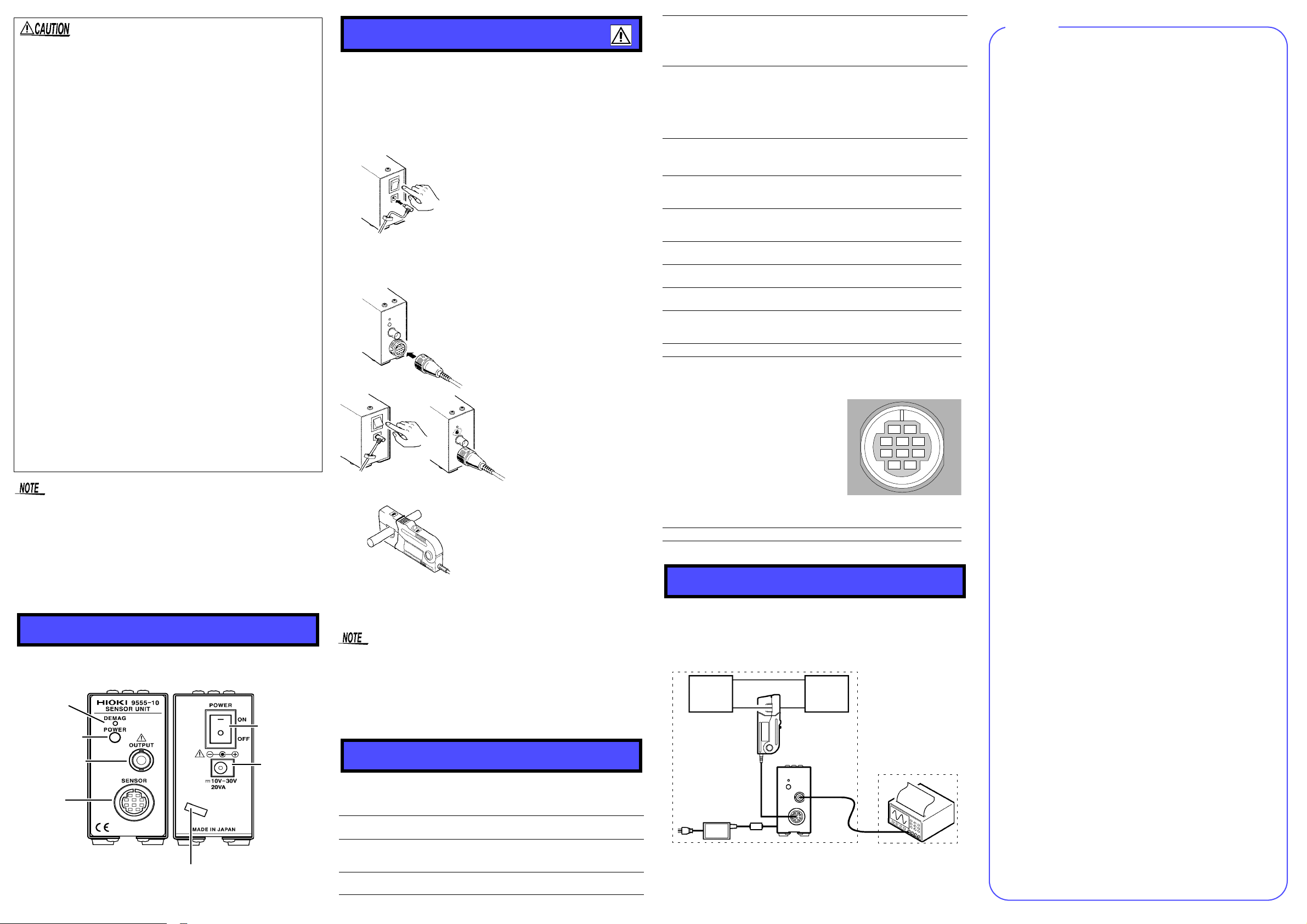
Connector Pin Configuration
1.GND
2.+12 Vout
3.-12 Vout
4.GND
5.Signal input
6.GND
7.DEMAG
8.NC
9.NC
10.GND
Compatible Connector
RM515EPA-10PC(HIROSE ELECTRIC CO., LTD.)
Application Example
If the distance between the location of the current to be measured and the measuring instrument is greater than the length
of the CURRENT SENSOR cable, measurement is possible by
extending from the 9555-10 analog output. Note that there may
be effects such as noise.
 Loading...