

Page 1

9518-01
Instruction Manual
GB-IB INTERFACE
For 3532-50, 3522-50, 3511-50 LCR HiTESTER
Sept. 2018 Revised edition 10
9518A983-10 18-09H
EN
Page 2

Page 3

Contents
Introduction i
Chapter 1 Before Use 1
1.1 Check of External Appearance and Accessories 1
1.2 Shipping Precautions
1.3 Points for Attention During Use
1.4 Installing the GP-IB Interface
Chapter 2 Overview 5
2.1 Introduction to the 9518-01 GP-IB INTERFACE 5
2.2 Specifications
Chapter 3 Names of Parts 7
3.1 Controls and Connections 7
Chapter 4 Operation 9
4.1 Setting the GP-IB Device Address 9
4.2 Communication Methods by the GP-IB
4.3 Message Format
11
12
2
3
4
6
4.4 Headers 13
4.5 Data Formats
4.6 Message Terminators
4.7 Separators
4.8 Abbreviation of Compound Commands
4.9 Output Queue
4.10 Input Buffer
4.11 Status Model
4.12 Status Byte Register
4.13 Event Registers
4.14 GP-IB Commands
9518A983-10
4.3.1 Program Message 12
4.3.2 Response Messages 12
14
15
15
16
17
18
19
20
22
28
Page 4

Chapter 5 Command Reference for the
3532-50/3522-50 29
5.1 Command Summary 30
5.2 Format of Command Explanations
5.3 Particular Commands
5.4 Commands Specific to the 3532-50/3522-50
5.5 Response Format for Queries as Numerical Value
5.6 Initialization Items
34
35
42
92
94
Chapter 6 Command Reference for 3511-50 95
6.1 Command Summary 95
6.2 Format of Command Explanations
6.3 Particular Commands
6.4 Commands Specific to the 3511-50
98
99
106
Chapter 7 Sample Programs 133
Chapter 8 Device Compliance Statement 145
Chapter 9 Troubleshooting 149
Page 5

────────────────────────────────────────────────────
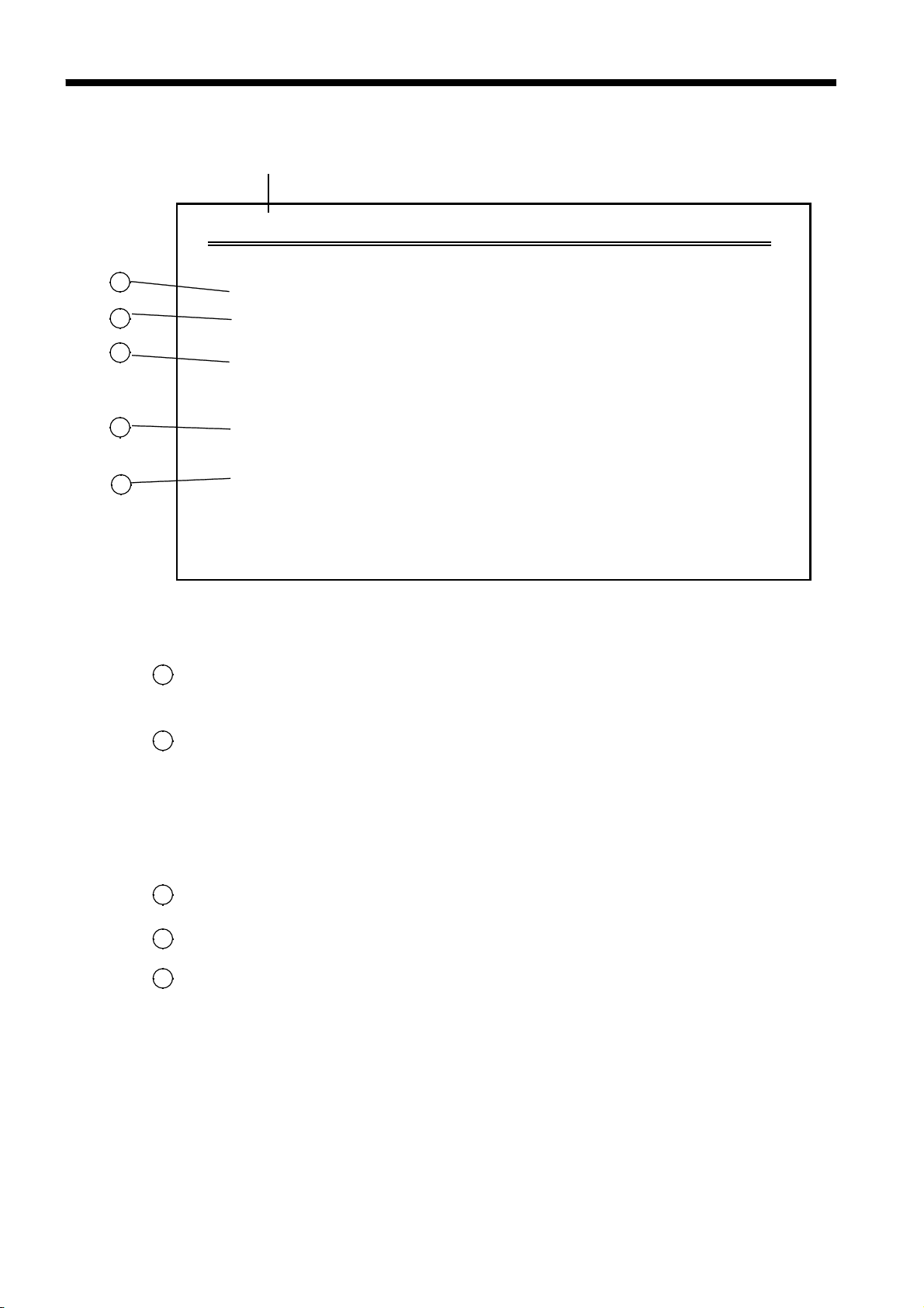
Introduction
Thank you for purchasing the HIOKI 9518-01 GP-IB INTERFACE for the
3532-50, 3522-50 and 3511-50 LCR HiTESTERs.
To obtain maximum performance from the product, please read this manual
first, and keep it handy for future reference.
This manual contains information and warnings essential for safe operation
of the product and for maintaining it in safe operating condition. Before
using the product, be sure to carefully read the following safety notes.
The following symbols in this manual indicate the relative importance of
cautions and warnings.
i
WARNING
CAUTION
NOTE
Indicates that incorrect operation presents a significant
hazard that could result in serious injury or death to
the user.
Indicates that incorrect operation presents a possibility
of injury to the user or damage to the product.
Advisory items related to performance or correct operation
of the product.
────────────────────────────────────────────────────
Page 6

ii
────────────────────────────────────────────────────
────────────────────────────────────────────────────
Page 7

1
────────────────────────────────────────────────────
Chapter 1
Before Use
1.1 Check of External Appearance and Accessories
When you receive the product, inspect it carefully to ensure that no damage
occurred during shipping.
In particular, check the accessories, panel switches, and connectors. If
damage is evident, or if it fails to operate according to the specifications,
contact your dealer or Hioki representative.
(1) 9518-01 GP-IB INTERFACE
(2) This instruction manual
────────────────────────────────────────────────────
1.1 Check of External Appearance and Accessories
Page 8
2
────────────────────────────────────────────────────
1.2 Shipping Precautions
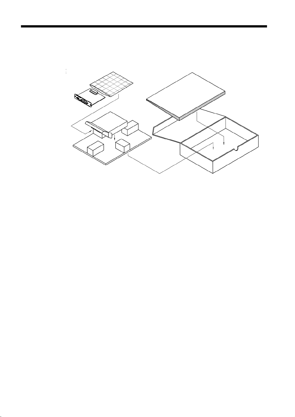
If reshipping the unit, preferably use the original packing.
If this is not available, use the following procedure.
1. Wrap the unit in plastic sheeting.
2. After wrapping cushioning material around the unit, pack it into a
cardboard box, and then seal up the box with adhesive tape.
────────────────────────────────────────────────────
1.2 Shipping Precautions
Page 9

3
────────────────────────────────────────────────────
1.3 Points for Atte ntion During Use
(1) If you change the device address of the 3532-50/3522-50/3511-50 while
using it, you should immediately turn the power off and on again. If you do
not do so, the address change will not be registered by the bus, and problems
will occur.
(2) Always be sure to secure the GP-IB cable to the 9518-01 unit by tightening
up the fixing screws provided.
(3) Program messages sent just after the power has been turned on are executed
after the self test has terminated.
(4) It is vital that the proper data format is used when inputting commands with
data values to the 3532-50/3522-50/3511-50 unit.
(5) For details of the various functions, refer to the instruction manuals for the
3532-50/3522-50/3511-50 unit.
────────────────────────────────────────────────────
1.3 Points for Attention During Use
Page 10
4
────────────────────────────────────────────────────
1.4 Installing the GP-IB Interface
WARNING
CAUTION
To avoid electric shock accident, before removing or replacing an input
module, confirm that the instrument is turned off and that the power cord
and connection cables are disconnected.
The mounting screws must be firmly tightened or the input unit may not
perform to specifications, or may even fail.
To avoid the danger of electric shock, never operate the product with an
input module removed. To use the product after removing an input
module, install a blank panel over the opening of the removed module.
When inserting in the interface, hold the metal plate. Directly touching the
board may cause static electricity and lead to damage of the instrument.
(Using the wrist strap for preventing static electricity when inserting is
recommended.)
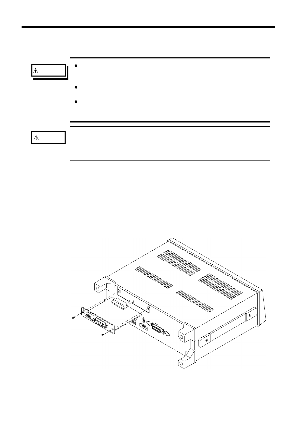
The space for fitting the 9518-01 GP-IB INTERFACE in the rear panel of
the 3532-50/3522-50/3511-50 are covered with a blanking plate. Follow
these three steps to install the 9518-01 interface:
1. Remove the fixing screws, and take off the blanking plate.
2. Insert the 9518-01 GP-IB INTERFACE into the exposed slot in the rear of
the unit in the figure below.
3. Push the 9518-01 firmly into place, and fix with the screws removed in
step 1.
────────────────────────────────────────────────────
1.4 Installing the GP-IB Interface
Page 11

5
────────────────────────────────────────────────────
Chapter 2
Overview
2.1 Introduction to the 9518-01 GP-IB INTERFACE
By connecting the 9518-01 GP-IB INTERFACE to the 3532-50/352250/3511-50, it is possible to control the main unit via the GP-IB bus. This
unit is compliance with the following standard.
NOTE
Compliance standard : IEEE 488.1-1987
Further, the 9518-01 is designed with reference to the following standard:
Reference standard : IEEE 488.2-1987
On the 9518-01, if the outp ut queue becomes full, i t is cleared and a
query error is generated. This differs from the IEEE 488.2 specificat ion,
which only stip ulates the clearin g of the output queue and the out putt ing
of a query error when a deadlock state occurs, that is, when both t he
input buffer and the out put queue have become full, and continuation of
processing has become impossible.
────────────────────────────────────────────────────
2.1 Introduction to the 9518-01 GP-IB INTERFACE
Page 12

6
────────────────────────────────────────────────────
2.2 Specifications
Interface Functions
SH1
AH1
T6
L4
SR1
RL1
PP0
DC1
All source handshake functions
All acceptor handshake functions
Basic talk functions
Serial poll function
No talk-only mode
The talker cancellation function with MLA (My Listen
Address)
Basic listener functions
No listen-only mode
The listener cancellation function with MTA (My Talk
Address) is provided.
All service request functions
All remote/local functions
No parallel polling function
All device clear functions
DT1
C0
All device trigger functions
No controller function
ASCII codes are used.
────────────────────────────────────────────────────
2.2 Specifications
Page 13
7
────────────────────────────────────────────────────
Chapter 3
Names of Parts
3.1 Controls and Connections
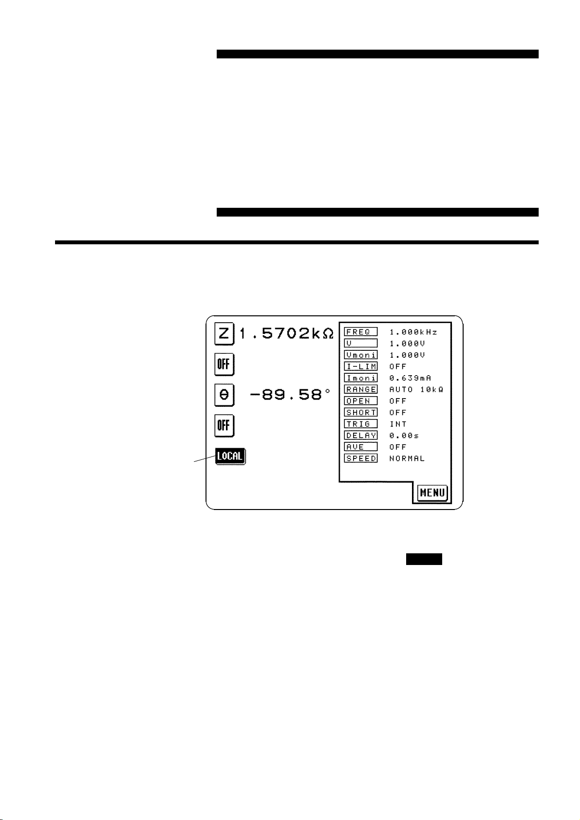
(1) 3532-50/3522-50 Initial Screen
LOCAL key
LOCAL key
During communications (in the remote state), the
remote state is displayed on the screen. Press this key to resume the normal
state (local state).
However, this key is disabled if the GP-IB controller has put the unit into
the local lock out state. (Pressing the key has no effect.)
In the remote state, the initial screen is forcibly displayed excluding the
following conditions.
・
When executing OPEN/SHORT correction or sending the execution
command (correction execution screen appears).
・
When the magnification display screen appears.
LOCAL
key to release the
────────────────────────────────────────────────────
3.1 Controls and Connections
Page 14
8
A
────────────────────────────────────────────────────
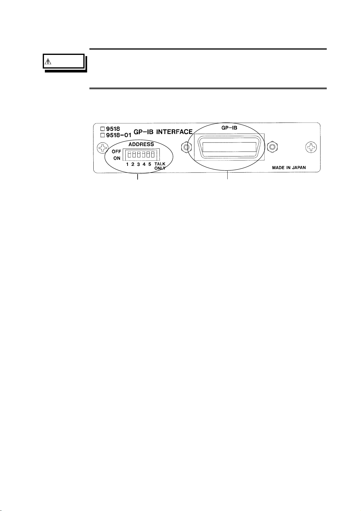
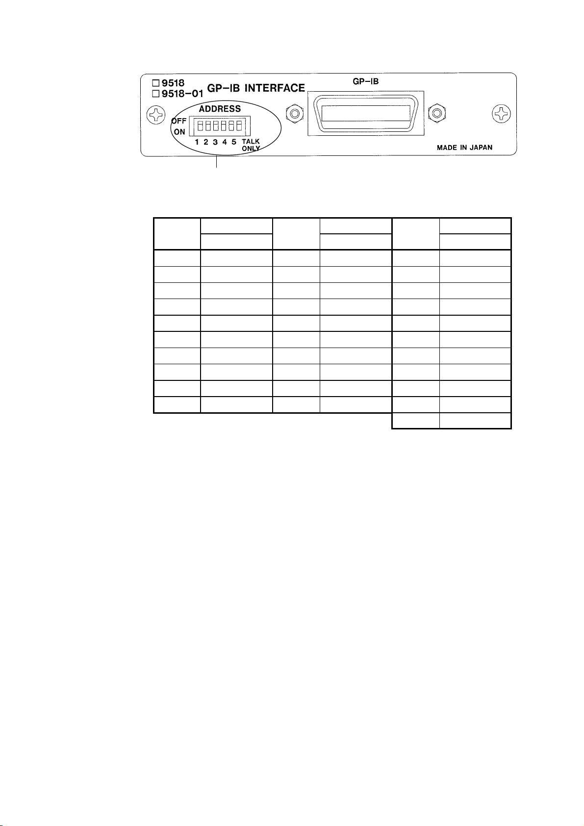
(2) 9518-01 GP-IB INTERFACE outer panel
WARNING
In order t o prevent any danger of elec tr ic shock to the operator, check
carefull y th at the power c abl e a nd t he connect ors to the 3 532-50 /35 2250/3511-50 have been removed first, before c onne c ti ng t he GP-IB cable
to this connector.
ddress switches GP-IB connector
Address swi tches
These are used to set the device address of the 3532-50/3522-50 units on the
GP-IB bus. For how to set these switches, refer to Section 4.1, "Setting the
GP-IB Device Address."
GP-IB connector
Connect the GP-IB cable to this connector.
────────────────────────────────────────────────────
3.1 Controls and Connections
Page 15

9
────────────────────────────────────────────────────
Chapter 4
Operation
4.1 Setting the GP-IB Device Address
・
The address of the 3532-50/3522-50/3511-50 units (called the device) on the
GP-IB bus can be set to any number from 0 to 30.
NOTE
・
Use the Address switches on the GP-IB panel to set the device address.
・
On dispatch from the factory, this address is initially set to 1.
・
If this address is (apparently) set to 31, i.e. if all the switches are in the ON
position, then the bus lines of the 3532-50/3522-50/3511-50 are disabled.
・
Always the Address switch for TALK ONLY is in the OFF position, since it
is not used.
If you change the bus address while the 3532-50, 3522-50 or 3511-50 is
being used, then you should i mmediat ely turn the power off and on again.
If this is not done, the address will not be ch a nged to the new one.
────────────────────────────────────────────────────
4.1 Setting the GP-IB Device Address
Page 16
10
────────────────────────────────────────────────────
Address switches
Address
Switch settings
Address
Switch settings
Address
Switch settings
12345 12345 12345
0 00000 10 01010 20 00101
1 10000 11 11010 21 10101
2 01000 12 00110 22 01101
3 11000 13 10110 23 11101
4 00100 14 01110 24 00011
5 10100 15 11110 25 10011
6 01100 16 00001 26 01011
7 11100 17 10001 27 11011
8 00010 18 01001 28 00111
9 10010 19 11001 29 10111
0: OFF 1: ON 30 01111
────────────────────────────────────────────────────
4.1 Setting the GP-IB Device Address
Page 17
11
────────────────────────────────────────────────────
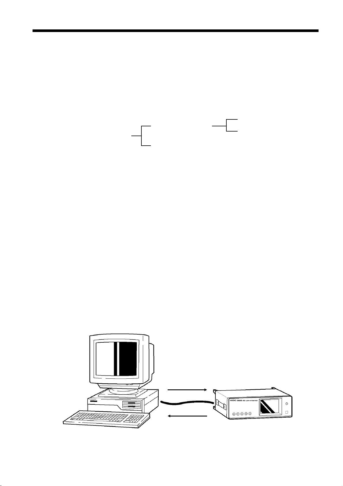
4.2 Communication Methods by the GP-IB
・
In order to control the 3532-50/3522-50/3511-50 by the GP-IB, there are
several kinds of messages.
・
Of these, program messages are those received by the 3532-50/3522-
50/3511-50 from the computer, while response messages are those sent from
the 3532-50/3522-50/3511-50 to the computer.
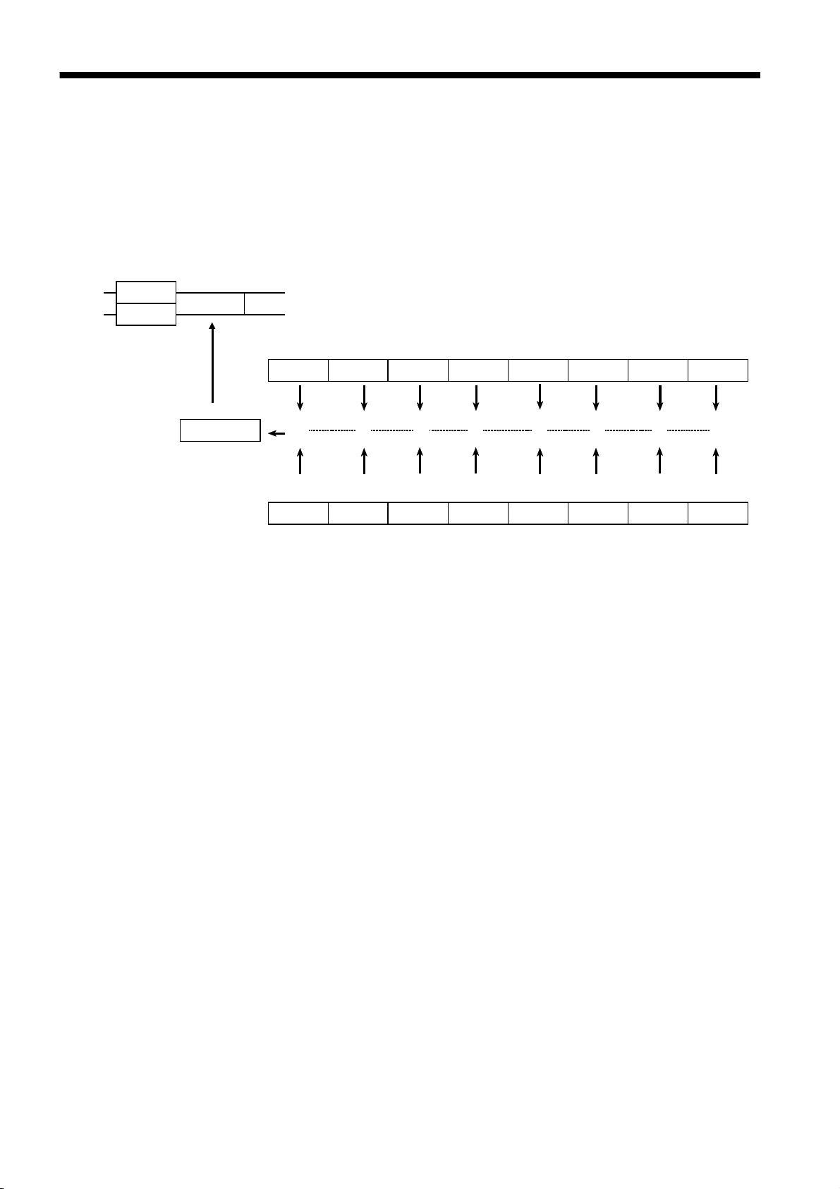
Command messages
Program messages
Messages
Response messages
(1) Program messages
Program messages are command messages or query messages.
Query messages
・
Command messages
are orders for controls of the 3532-50/3522-50/
3511-50, such as for making measurement condition settings or for reset or
the like.
Example FREQUENCY
<data>
(Command message which sets the frequency)
・
Query messages
are orders for responses relating to results of operation,
results of measurement, or the state of 3532-50/3522-50/3511-50 settings.
(A question mark "?" is suffixed at the end of the command.)
Example FREQUENCY?
(Queries the current frequency)
(2) Response messages
It represents the response data for query messages from the 3532-50/352250/3511-50.
Example FREQUENCY 1.000E+03
(Current frequency is 1 kHz.).
Computer
Program messages
Response messages
────────────────────────────────────────────────────
4.2 Communication Methods by the GP-IB
3532-50/3522-50/3511-50
Page 18

12
────────────────────────────────────────────────────
4.3 Message Format
The commands for the 3532-50/3522-50/3511-50 are as far as possible
mnemonic. Furthermore, all commands have a long form, and an
abbreviated short form.
4.3.1 Program Message
The program message is made up from header and data portions
Example
:
Command message to set frequency to 1 kHz
FREQUENCY 1000
1 2 3
1
Header portion
Space separating header portion and data portion.
2
3
Data portion (ASCII-format text or numeric values.
Some messages have no data portions...query messages, etc.)
A command header can be abbreviated. The whole command form is
referred to as the "long form" and the abbreviated form as the "short form."
In this manual, the short form is written in upper case letters, and then this
is continued in lower case letters so as to constitute the long form. Either of
these forms will be accepted during operation, but intermediate forms will
not be accepted. Further, during operation both lower case letters and upper
case letters will be accepted without distinction.
For "FREQUENCY", either "FREQuency" (the long form) or "FREQ" (the
short form) will be accepted. However, any one of "FREQU", or "FRE" is
wrong and will generate an error.
4.3.2 Response Messages
It represents the response message for query messages from the 353250/3522-50/3511-50.
Response messages generated by the 3532-50/3522-50/3511-50 are in long
form and in upper case letters.
Example FREQUENCY 1.000E+03
(Current frequency is 1 kHz.)
NOTE
────────────────────────────────────────────────────
4.3 Message Format
If an error occurs when the query message is received, the query does not
produce response message.
Page 19

13
(
)
────────────────────────────────────────────────────
4.4 Headers
(1) Program message headers
There are three types of header: simple commands, compound commands,
and standard common commands.
・
Simple command header
A header consisting of a single word beginning with a letter.
Examples :HEADer
・
Compound command header
A header consisting of a sequence of words separated by colons.
Examples :BEEPer:KEY, RANGe:AUTO
・
Standard command header
A header begins with an asterisk (*) to indicate that it is a standard
command, and continues with a standard command stipulated by IEEE
488.2.
Examples
*
RST
, etc.
, etc.
, etc.
NOTE
(2) Response message
Headers in response messages can be enabled or disabled by using the
"HEADer" command.
Example
(Query message
When frequency is set to 1 kHz:
:FREQUENCY?
asking for the current setting of the frequency.
Response message when headers are on.
:FREQUENCY 1000
Headerportion)(Dataportion
Response message when headers are off.
(Data portion only)
1000
The headers are set to off when powering on.
)
────────────────────────────────────────────────────
4.4 Headers
Page 20

14
────────────────────────────────────────────────────
4.5 Data Formats
The 3532-50/3522-50/3511-50 use character string data and decimal numeric
data, and the type used varies according to the command in question.
(1) Character data
Character string data must always begin with an alphabetic character, and
the characters following can be either alphabetic characters or numerals.
Although in character data either upper case letters or lower case letters are
accepted, response messages output by the 3532-50/3522-50/3511-50 are
always in upper case letters.
Example :TRIGger INT
(2) Decimal data
The numeric data values are all represented in decimal, in three formats
identified as NR1, NR2 and NR3, and each of these can appear as either a
signed number or an unsigned number. Unsigned numbers are taken as
positive.
Further, if the accuracy of a numerical value exceeds the limit which the
3532-50/3522-50/3511-50 can deal, it is rounded off. (5 and above is
rounded up; 4 and below is rounded down).
NR1 format - integer data.
Examples +12, -23, 34
NR2 format - fixed point numbers.
Examples +1.23, -23.45, 3.456
NR3 format - floating point numbers.
Examples +1E-2, -2.3E+4
The term "NRf format" includes all these three formats.
When the 3532-50/3522-50/3511-50 is receiving it accepts NRf format, but
when it is sending response messages it utilizes whichever one of the
formats NR1 to NR3 is indicated in the specified command.
Examples :RANGe 6
:RANGe +6.012
:RANGe 0.0006E4
────────────────────────────────────────────────────
4.5 Data Formats
Page 21

15
────────────────────────────────────────────────────
4.6 Message Terminators
The 3532-50/3522-50/3511-50 recognize either a linefeed character (LF) or
the EOI signal, or both, as message terminators.
To terminate a response message, the 3532-50/3522-50/3511-50 always
provide the appropriate EOI signal, and also sends a terminating character
sequence. By the use of the ":TRANsmit:TERMinator" command either of
the following can be selected as response message terminator sequence:
(1) LF (linefeed only)
(2) CR + LF (carriage return plus linefeed)
NOTE
When powering on, the message terminators are (1).
A detailed explanation of the "TRANsmit:TERMinator" command is given in
Section 5.4.
4.7 Separators
(1) Message unit separator
A semicolon (;) is used as a message unit separator when it is desired to set
out several messages on a single line.
Example :RANGe:AUTO ON;:BEEP:KEY ON
NOTE
When messages are combined in this way, if a syntax error occurs, all
subsequent messages up to the next terminator will be ignored.
(2) Header separator
In a message which has a header and data, a space (represented by " " in
the examples) is used as the header separator to separate the header from the
data.
Example :LEVel V
; *
IDN?
(3) Data separator
If a message has several data items, commas (,) are required as data
separators for separating these data items from one another.
Example :COMParator:FLIMit:ABSolute
────────────────────────────────────────────────────
<lower limit> ,<upper limit>
4.6 Message Terminators
Page 22

16
────────────────────────────────────────────────────
4.8 Abbreviation of Compound Commands
When several compound headers have a common head portion (for example,
:BEEPer:KEY
and
:BEEPer:COMParator
writing them directly following on from one another, this common portion
(
:BEEPer:
in this example) can be omitted from each command.
This common portion is called "the current path", by analogy with the
general concept of the current directory in the directory structure of UNIX or
MSDOS, and until it is cleared the analysis of following commands is
performed by deeming them to be preceded by the current path which has
been curtailed in the interests of brevity. This manner of using the current
path is shown in the following example:
Normal expression
:BEEPer:KEY ON;:BEEPer:COMParator NG
Abbreviated expression
:BEEPer: KEY ON;COMParator NG
, etc.), then, when and only when
This becomes the current path, and can be
curtailed from the following messages.
The current path is cleared when the power is turned on, when a colon (:)
appears at the start of a command, and when a message terminator is
detected.
Messages of standard command form can be executed without relation to the
current path. Further, they have no effect upon the current path.
With the 3532-50/3522-50, there are 11 possible current paths:
:APPLication:DISPlay
:BEEPer:
:COMParator:FLIMit:
:COMParator:SLIMit:
:CORRection:
:LEVel:
:LIMiter:
:MEASure:
:RANGe:
:TRIGger:
:SCALe:
With the 3511-50, there are 4 possible current paths:
:COMParator:
:CORRection:
:RANGe:
────────────────────────────────────────────────────
4.8 Abbreviation of Compound Commands
:BEEPer:
Page 23

17
────────────────────────────────────────────────────
4.9 Output Queue
Response messages accumulate in the output queue and are read out as data
and cleared by the controller.
The output queue is also cleared in the following circumstances:
・
When a device clear is issued.
・
Whenthepoweristurnedoffandturnedonagain.
The 3532-50/3522-50/3511-50 have an output queue of 300 bytes capacity.
If the response messages overflow this limit of 300 bytes, a query error is
generated, and the output queue is cleared. Further, if a new message is
received while the output queue still contains data, the output queue is
cleared, and a query error is generated.
────────────────────────────────────────────────────
4.9 Output Queue
Page 24

18
────────────────────────────────────────────────────
4.10 Input Buffer
The 3532-50/3522-50/3511-50 have an input buffer of 300 bytes capacity.
Messages which are received are put into this buffer and executed in order.
If the data accumulated in this buffer exceeds 300 bytes the buffer becomes
full, and until a space again becomes available in the buffer the GP-IB
interface bus goes into the waiting state.
────────────────────────────────────────────────────
4.10 Input Buffer
Page 25
19
q
────────────────────────────────────────────────────
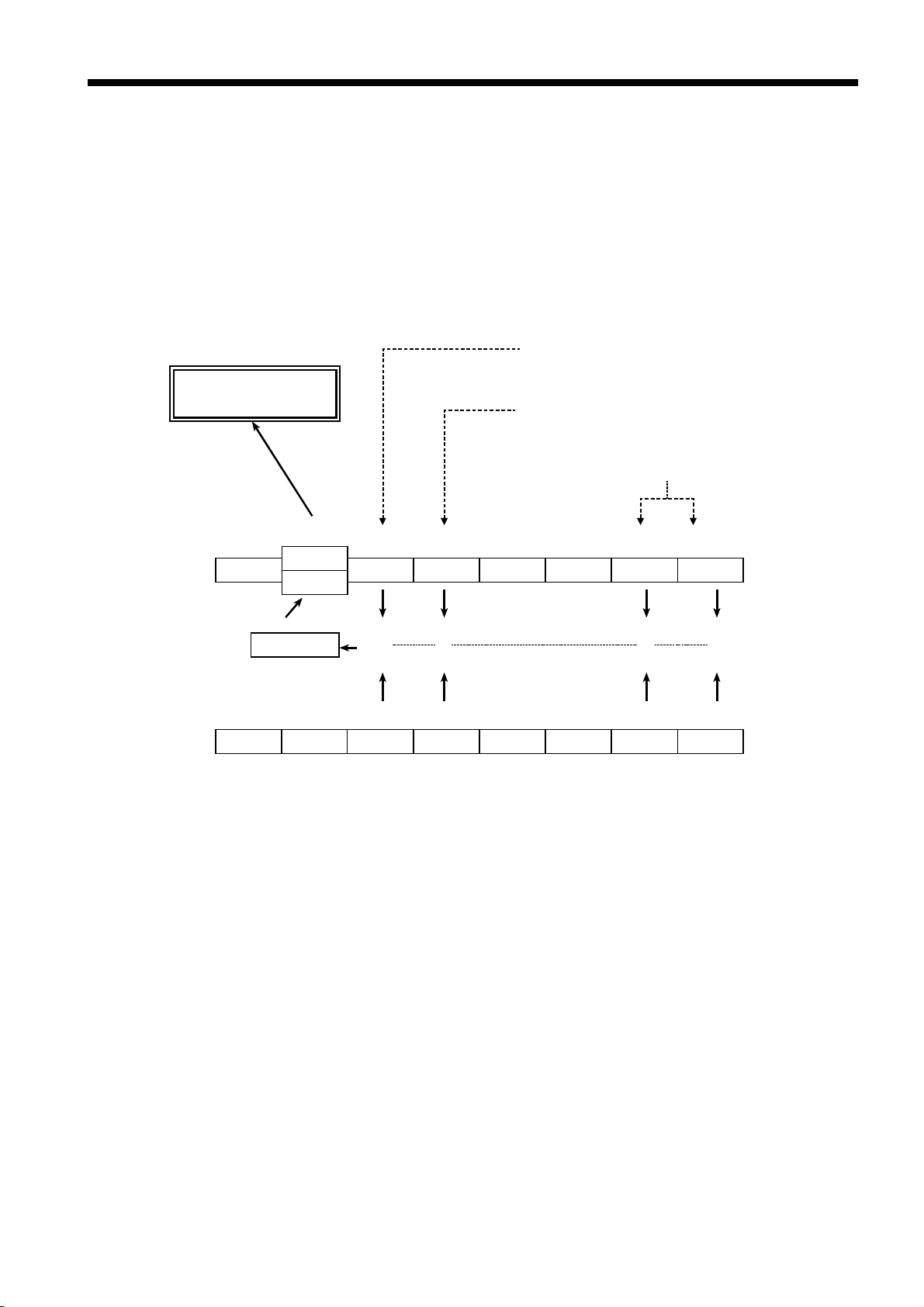
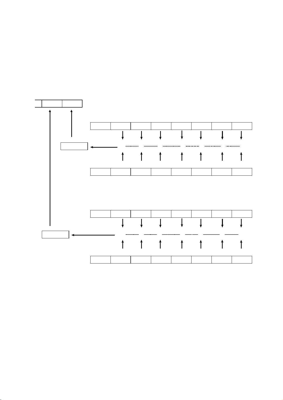
4.11 Status Model
In its implementation of the serial polling function using service requests, the
3532-50/3522-50/3511-50 employ the status model specified by IEEE 488.2.
The term "event" refers to any phenomenon which generates a service
request.
Status byte register (STB)
Represents standard event register
Generation of service
request (SRQ)
Data is present in the output queue
Bits represent corresponding event registers
bit 7 bit 5 bit 4 bit 3 bit 2 bit 1 bit 0
bit 7 bit 6 bit 5 bit 4 bit 3 bit 2 bit 1 bit 0
bit 6
RQS
MSS
Logical sum & & & &
X ESB MAV ESB1 ESB0
ESB MAV ESB1 ESB0
Service request enable register (SRER)
Generation of Service Re
uests
The status byte register holds information relating to the event registers and
the output queue.
It is further possible to use the service request enable register as a mask to
select the items required. If any of the bits selected by the mask becomes 1,
bit 6 (the master summary status or MSS bit) is also set to 1, an RQS
message is generated, and this generates a service request.
────────────────────────────────────────────────────
4.11 Status Model
Page 26
20
────────────────────────────────────────────────────
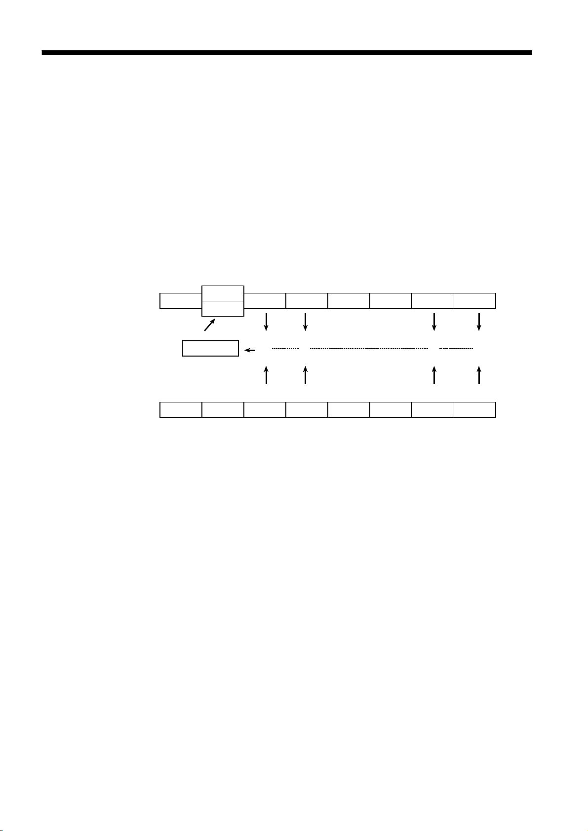
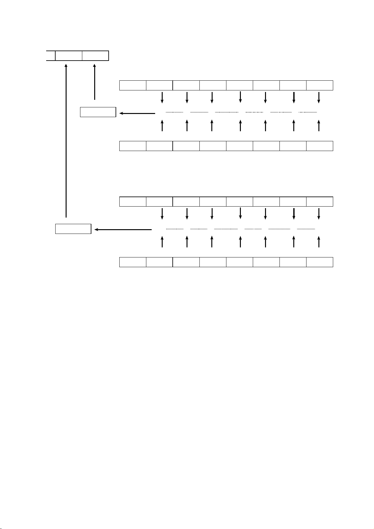
4.12 Status Byte Register
(1) Status byte register (STB)
The status byte register is an 8-bit register whose contents are output from
the 3532-50/3522-50/3511-50 to the controller, when serial polling is being
performed.
If any bit in the status byte register has changed from 0 to 1 (provided that it
is a bit which has been set in the service request enable register as a bit
which can be used), then the MSS bit is set to 1. Simultaneously with this
the RQS bit is also set to 1, and a service request is generated.
Status byte register (STB)
bit 7 bit 5 bit 4 bit 3 bit 2 bit 1 bit 0
Unused ESB MAV Unused Unused ESB1 ESB0
bit 6
RQS
MSS
Logical sum & & & &
bit 7 bit 6 bit 5 bit 4 bit 3 bit 2 bit 1 bit 0
Unused X ESB MAV Unused Unused ESB1 ESB0
Service request enable register (SRER)
The RQS bit is synchronized with service requests, and is read out and
simultaneously cleared when serial polling is being performed. Although the
MSS bit is only read out on an"*
STB?"
query, on a"*
command for
CLS"
example it is not cleared until the event is cleared.
────────────────────────────────────────────────────
4.12 Status Byte Register
Page 27

21
────────────────────────────────────────────────────
Status Byte Register Bit Assignments
Bit 7
Bit 6
RQS
MSS
Bit 5
ESB
Bit 4
MAV
Bit 3
Bit 2
Bit 1
ESB1
Bit 0
ESB0
Unused.
Set to 1 when a service request is issued.
Logical sum of the other bits of the status byte register
Standard event summary (logical sum) bit
Shows a logical sum of the standard event status register.
Message available.
Shows that there is at least one message in the output queue.
Unused.
Unused.
Event summary bit 1
Shows a logical sum of event status register 1.
Event summary bit 0
Shows a logical sum of event status register 0.
(2) Service request enable register (SRER)
This register masks the status byte register. Setting a bit of this register to 1
enables the corresponding bit of the status byte register to be used.
────────────────────────────────────────────────────
4.12 Status Byte Register
Page 28
22
)
────────────────────────────────────────────────────
4.13 Event Registers
(1) Standard event status register (SESR)
The standard event status register is an 8-bit register. If any bit in the
standard event status register is set to 1 (after masking by the standard event
status enable register), bit 5 (ESB) of the status byte register is set to 1.
Status byte register(STB
RQS
MSS
bit 5
ESB MA
Standard event status register (SESR)
bit 7 bit 6 bit 5 bit 4 bit 3 bit 2 bit 1 bit 0
PON URQ CME EXE DDE QYE RQC OPC
Logical sum & & & & & & & &
bit 7 bit 6 bit 5 bit 4 bit 3 bit 2 bit 1 bit 0
PON URQ CME EXE DDE QYE RQC OPC
Standard event status enable register (SESER)
The standard event status register is cleared in the following three situations:
1. When a"*
2. When an"*
command is received.
CLS"
ESR?"
query is received.
3. When the unit is powered on.
────────────────────────────────────────────────────
4.13 Event Registers
Page 29

23
────────────────────────────────────────────────────
(2) Standard event status enable register (SESER)
Setting any bit of the standard event status enable register to 1 enables the
corresponding bit of the standard event status register to be accessed.
Standard Event Status Register (SESR) Bit Assignments
Bit 7
PON
Bit 6
URQ
Bit 5
CME
Bit 4
EXE
Power on flag.
When the power is turned on, or on recovery from a power
cut, this bit is set to 1.
User request.
Not used by the 3532-50/3522-50/3511-50.
Command error.
When a command which has been received contains a
syntactic or semantic error, this bit is set to 1.
・
The command is not supported by the 3532-50/352250/3511-50.
・
There is a mistake in a program header.
・
The number of data parameters is wrong.
・
The format of the parameters is wrong.
Execution error.
When for some reason a command which has been received
cannot be executed, this bit is set to 1.
・
The designated data value is outside the set range.
・
The designated data value is not acceptable.
・
Execution is impossible because some other function is
being performed.
Bit 3
DDE
Bit 2
QYE
Bit 1
RQC
Bit 0
OPC
Device dependent error.
When a command cannot be executed due to some cause other
than a command error, a query error, or an execution error,
this bit is set to 1.
・
Execution is impossible due to an abnormality inside the
3532-50/3522-50/3511-50.
・
During open or short circuit compensation, valid data cannot
be obtained.
Query error.
This bit is set to 1 when a query error is detected by the
output queue control.
・
When an attempt has been made to read the output queue
when it is empty.
・
When the data overflows the output queue.
・
When data in the output queue has been lost.
Request for controller authority.
Not used by the 3532-50/3522-50/3511-50.
Operation terminated.
This bit is set to 1 when an "*OPC" command is executed,
when the operation of all the messages up to the "*OPC"
command has been completed.
────────────────────────────────────────────────────
4.13 Event Registers
Page 30
24
────────────────────────────────────────────────────
(3) Event status registers specific to the 3532-50/3522-50/3511-50 (ESR0
and ESR1)
Two 8-bit event status registers are provided for managing events on the
3532-50/3522-50/3511-50. If any bit in one of these event status registers is
set to 1 (after masking by the corresponding event status enable register), the
following happens:
・
For event status register 0, bit 0 of the status byte register (ESB0) is set to 1.
・
For event status register 1, bit 1 of the status byte register (ESB1) is set to 1.
bit 1 bit 0
ESB1 ESB0
Logical sum & & & & & & &
3532-50/3522-50
Event status register 0 (ESR0)
bit 7 bit 6 bit 5 bit 4 bit 3 bit 2 bit 1 bit 0
Unused COF LOF IOF IUF IDX EOM CEM
bit 7 bit 6 bit 5 bit 4 bit 3 bit 2 bit 1 bit 0
Unused COF LOF IOF IUF IDX EOM CEM
Event status enable register 0 (ESER0)
Event status register 1 (ESR1)
bit 7 bit 6 bit 5 bit 4 bit 3 bit 2 bit 1 bit 0
Unused AND SLO SIN SHI FLO FIN FHI
Logical sum & & & & & & &
bit 7 bit 6 bit 5 bit 4 bit 3 bit 2 bit 1 bit 0
Unused AND SLO SIN SHI FLO FIN FHI
Event status enable register 1 (ESER1)
────────────────────────────────────────────────────
4.13 Event Registers
Page 31

25
────────────────────────────────────────────────────
Event status register 0 and event status register 1 are cleared in the following
three situations:
1. When a
2. When an
"*CLS"
command is received.
":ESR0?"
query (for event status register 0) or
":ESR1?"
query (for
event status register 1) is received.
3. When the unit is powered on.
Event Status Register 0 (ESR0) Bit Assignments
Bit 7
Bit 6
COF
Bit 5
LOF
Bit 4
IOF
Bit 3
IUF
Bit 2
IDX
Bit 1
EOM
Bit 0
CEM
Unused
Constant current and constant voltage overflow
Limits overflow
Impedance overflow
Impedance underflow
Data sampling completed
Measurement completed
Compensation data measurement completed
Event Status Register 1 (ESR1) Bit Assignments
Bit 7
Bit 6
AND
Bit 5
SLO
Bit 4
SIN
Bit 3
SHI
Bit 2
FLO
Bit 1
FIN
Bit 0
FHI
Unused
Logical product (AND) of comparison results
Second parameter below lower limit
Second parameter within limits
Second parameter above upper limit
First parameter below lower limit
First parameter within limits
First parameter above upper limit
────────────────────────────────────────────────────
4.13 Event Registers
Page 32
26
────────────────────────────────────────────────────
bit 1 bit 0
ESB1 ESB0
Logical sum & & & & & & &
3511-50
Event status register 0 (ESR0)
bit 7 bit 6 bit 5 bit 4 bit 3 bit 2 bit 1 bit 0
CEM SOF SUF MOF MUF IDX EOM Unused
bit 7 bit 6 bit 5 bit 4 bit 3 bit 2 bit 1 bit 0
CEM SOF SUF MOF MUF IDX EOM Unused
Event status enable register 0 (ESER0)
Event status register 1 (ESR1)
bit 7 bit 6 bit 5 bit 4 bit 3 bit 2 bit 1 bit 0
Unused AND SLO SIN SHI FLO FIN FHI
Logical sum & & & & & & &
bit 7 bit 6 bit 5 bit 4 bit 3 bit 2 bit 1 bit 0
Unused AND SLO SIN SHI FLO FIN FHI
Event status enable register 1 (ESER1)
────────────────────────────────────────────────────
4.13 Event Registers
Page 33

27
────────────────────────────────────────────────────
Event status register 0 and event status register 1 are cleared in the following
three situations:
1. When a
2. When an
"*CLS"
command is received.
":ESR0?"
query (for event status register 0) or
event status register 1) is received.
3. When the unit is powered on.
Event Status Register 0 (ESR0) Bit Assignments
Bit 7
CEM
Bit 6
SOF
Bit 5
SUF
Bit 4
MOF
Bit 3
MUF
Bit 2
IDX
Compensation data measurement completed
Second parameter range over bit
Second parameter range under bit
First parameter range over bit
First parameter range under bit
Data sampling completed
":ESR1?"
query (for
Bit 1
EOM
Bit 0
Unused
Measurement completed
Unused
Event Status Register 1 (ESR1) Bit Assignments
Bit 7
Bit 6
AND
Bit 5
SLO
Bit 4
SIN
Bit 3
SHI
Bit 2
FLO
Unused
Logical product (AND) of comparison results (bit 1 a nd bit 4)
Second parameter below lower limit
Second parameter within limits
Second parameter above upper limit
First parameter below lower limit
Bit 1
FIN
Bit 0
FHI
────────────────────────────────────────────────────
First parameter within limits
First parameter above upper limit
4.13 Event Registers
Page 34

28
────────────────────────────────────────────────────
(4) Event status enable registers specific to the 3532-50/3522-50-50/3511- 50
(ESER0 and ESER1)
These event status enable registers mask the corresponding event status
registers.
(5) Summary of commands for writing and reading each of the registers
Register Read Write
Status byte register
Service request enable register
Standard event status register
Standard event status enable register
Event status register 0 :ESR0? ---Event status enable register 0 :ESE0? ESE0
Event status register 1 :ESR1? ---Event status enable register 1 :ESE1? ESE1
4.14 GP-IB Commands
The following commands are used for performing interface functions:
Command Function
Go To Local
GTL
LLO
DCL
SDC
GET
The remote state is canceled, and the system goes into the local
state.
Local Lock Out
All keys, including the LOCAL key, become inoperable.
Device Clear
Clears the input buffer and the output queue.
Selected Device Clear
Clears the input buffer and the output queue.
Group Execute Trigger
The same as the
"*TRG"
*STB?
*SRE? *SRE
*ESR?
*ESE? *ESE
standard command.
----
----
────────────────────────────────────────────────────
4.14 GP-IB Commands
Page 35

29
────────────────────────────────────────────────────
Chapter 5
Command Reference for the
3532-50/3522-50
────────────────────────────────────────────────────
Page 36

30
────────────────────────────────────────────────────
5.1 Command Summary
Standard Commands
Command Function
*CLS
*ESE
*ESE?
*ESR?
*IDN?
*OPC
*OPC?
*RST
*SRE
*SRE?
*STB?
*TRG
*TST?
*WAI
Clears event register.
Sets standard event status enable register (SESER).
Queries standard event status enable register (SESER).
Queries standard event status register (SESR).
Queries device ID.
Issues service request (SRQ) after execution completion.
Queries execution completion.
Device initialization.
Sets service request enable register (SRER).
Queries service request enable register (SRER).
Queries the status byte register.
Performs sampling once.
Queries the result of the self-test.
Waits until all execution is fully completed.
Ref
page
35
35
36
36
37
37
37
38
39
39
40
40
41
41
Specific commands
Command Function
■
Display function
:APPLication:DISPlay:LIGHt
:APPLication:DISPlay:LIGHt?
:APPLication:DISPlay:M ONItor
:APPLication:DISPlay:MONItor ?
■
Averaging function
:AVERaging
:AVERaging?
■
Beep sound function
:BEEPer:COMParator
:BEEPer:COMParator?
:BEEPer:KEY
:BEEPer:KEY?
■
External DC bias function
Setting for LCD display.
Queries the setting for LCD display.
Setting for voltage and current monitors.
Queries the setting for voltage and current monitors.
Sets the number of measurement times for averaging.
Queries the number of measurement times for averaging.
Sets the beep sound for the comparator.
Queries the beep sound for the comparator.
Sets the beep sound for key input.
Queries the beep sound for key in put.
Ref
page
42
42
43
43
44
44
45
45
46
46
:BIAS
:BIAS?
────────────────────────────────────────────────────
5.1 Command Summary
Enables and disables the external DC bias function.
Queries the external DC bias function enablement
47
47
Page 37

31
────────────────────────────────────────────────────
Command Function
■
Cable length setting function
:CABLe
:CABLe?
■
Comparator function
:COMParator
:COMParator?
:COMParator:FLIMit
:ABSolute
:ABSolute?
:DEViation
Sets the cable length.
Queries the cable length.
Enables and disables the comparator function.
Queries the comparator function enablement.
(first parameter)
Sets the upper and lower limit values (absolute values).
Queries the upper and lower limit values (absolute values).
Sets the reference value and the upper and lower limit values
(deviation percentage values).
:DEViation? Queries the reference value and the upper and lower limit
values (deviation percentage values).
:MODE
:MODE?
:PERcent
Sets the first parameter setting mode.
Queries the first parameter setting mode.
Sets the reference value and the upper and lower limit values
(percentage values).
Ref
page
47
48
48
48
49
49
50
50
51
51
52
:PERcent?
:COMParator:SLIMit
:ABSolute
:ABSolute?
:DEViation
:DEViation?
:MODE
:MODE?
:PERcent
:PERcent?
■
Open and short circuit compensation function
:CORRection:DATA?
:CORRection:OPEN
Queries the reference value and the upper and lower limit
values (percentage values).
(second parameter)
Sets the upper and lower limit values (absolute values).
Queries the upper and lower limit values (absolute values).
Sets the reference value and the upper and lower limit values
(deviation percentage values).
Queries the reference value and the upper and lower limit
values (deviation percentage values).
Sets the second parameter setting mode.
Queries the second parameter setting mode.
Sets the reference value and the upper and lower limit values
(percentage values).
Queries the reference value and the upper and lower limit
values (percentage values).
Queries the open and short circuit compensation values.
Enables and disables the open circuit compensation function.
52
53
53
54
54
55
55
56
56
57
58
:CORRection:OPEN?
:CORRection:SHORt
:CORRection:SHORt?
■
Monitor function
:DISPlay:MONItor?
────────────────────────────────────────────────────
Queries the open circuit compensation function enablement.
Enables and disables the short circuit compensation
Queries the short circuit compensation function enablement.
Queries the monitored voltage and current.
5.1 Command Summary
59
60
61
61
Page 38

32
────────────────────────────────────────────────────
Command Function
■
Event register
:ESE0
:ESE0?
:ESE1
:ESE1?
:ESR0?
:ESR1?
■
Test frequency function
:FREQuency
:FREQuency?
■
Headers
:HEADer
:HEADer?
■
EXT I/O Output
:IO:OUTPut:DELay
:IO:OUTPut:DELay?
Sets event status enable register 0.
Queries event status enable register 0.
Sets event status enable register 1.
Queries event status enable register 1.
Queries event status register 0.
Queries event status register 1.
Sets the test frequency.
Queries the test frequency.
Enables and disables headers for the response message.
Queries headers enablement.
Sets the delay time for judgement result output EOM
―――――
output period in EXT I/O
Queries the delay time for judgement result output EOM
―――――
output period in EXT I/O
Ref
page
62
62
63
63
64
64
65
65
66
66
67
67
:IO:RESult:RESet
:IO:RESult:RESet?
■
Test signal level function
:LEVel
:LEVel?
:LEVel:CCURRent
:LEVel:CCURRent?
:LEVel:CVOLTage
:LEVel:CVOLTage?
:LEVel:VOLTage
:LEVel:VOLTage?
■
Limit function
:LIMiter
:LIMiter?
:LIMiter:CURRent
:LIMiter:CURRent?
:LIMiter:VOLTage
Sets output of judgment result signal line in EXT I/O
Queries output of judgment result signal line in EXT I/O
Sets the test signal level.
Queries the test signal level.
Sets the constant current level value.
Queries the constant current level value.
Sets the constant voltage level value.
Queries the constant voltage level value.
Sets the open circuit voltage level value.
Queries the open circuit voltage level value.
Enables and disables the limit setting function.
Queries the limit setting function enablement.
Sets the current limit value.
Queries the current limit value.
Sets the voltage limit value.
68
68
67
67
68
68
69
69
70
70
71
71
72
72
73
:LIMiter:VOLTage?
■
Panel load function
:LOAD
────────────────────────────────────────────────────
5.1 Command Summary
Queries the voltage limit value.
Transfers the specified panel number.
73
74
Page 39

33
────────────────────────────────────────────────────
Command Function
■
Normal testings
:MEASure?
:MEASure:ITEM
:MEASure:ITEM?
■
Parameter settings
:PARAmeter*
:PARAmeter*?
:PARAmeter* :DIGit
:PARAmeter* :DIGit?
■
Test range function
:RANGe
:RANGe?
:RANGe:AUTO
:RANGe:AUTO?
■
Panel saving function
(*:1 to 4)
Queries the data item.
Sets test parameter.
Queries test parameter.
Sets displayed parameters.
Queries displayed parameters.
Sets the number of displayed digits.
Queries the number of displayed digits.
Sets test range.
Queries test range setting.
Sets the automatic test ranging.
Queries the automatic test range setting.
Ref
page
75
77
78
79
79
80
80
81
82
83
83
:SAVE
:SAVE?
■
Scaling function
:SCALe
:SCALe?
:SCALe:FVALue
:SCALe:FVALue?
:SCALe:SVALue
:SCALe:SVALue?
■
Test speed function
:SPEEd
:SPEEd?
■
Terminators
:TRANsmit:TERMinator
:TRANsmit:TERMinator?
■
Trigger function
Saves the test conditions in specified panel number.
Queries the panel number in which data is saved.
Enables and disables the scaling function.
Queries the scaling function.
Sets the first parameters (a and b) in the scaling function.
Queries the first parameters (a and b) in the scaling function.
Sets the second parameters (a and b) in the scaling function.
Queries the second parameters (a and b) in the scaling
function.
Sets the testing speed.
Queries the testing speed.
Sets the terminator for the response message.
Queries the terminator for the response message.
84
84
85
85
86
86
87
87
88
88
89
89
:TRIGger
:TRIGger?
:TRIGger:DELAy
:TRIGger:DELAy?
────────────────────────────────────────────────────
Sets the type of trigger.
Queries the trigger setting.
Sets the trigger delay time.
Queries the trigger delay time.
90
90
91
91
5.1 Command Summary
Page 40
34
────────────────────────────────────────────────────
5.2 Format of Command Explanations
Command
(Example)
:AVERaging
■
Sets the number of measurement times for averaging.
1
Syntax
:AVERaging <data>
2
3
4
5
<data>
Function
Example
1
Specifies the syntax for the command (a space is represented by " " in this
Error
OFF (character data) or 2/4/8/16/32 /64 (numerical value in NR1
format)
・ Sets the desired number of times for averaging.
・ The numerical value can be in NRf format, but any digits after the
decimal point will be rounded.
Transmission :AVERaging 32
The count for averaging is set to 32.
If <data> is other than character data and numeric al value described
above, an execution error occurs.
syntax).
For a command that has parameters, specifies their format.
2
・
Numeric data values in the following formats
NR1: integer data
NR2: fixed point numbers
NR3: floating point numbers
・
Character d ata
Specifies the function of the command.
3
These are simple examples of the use of the command.
4
5
Specifies what types of error may occur.
For query commands, this time is the time taken when headers are on.
────────────────────────────────────────────────────
5.2 Format of Command Explanations
Page 41

35
────────────────────────────────────────────────────
5.3 Particular Commands
*CLS
■
Clears the event registers.
Syntax *
Function
Error
CLS
・
Clears all the event registers (SESR, ESR0, ESR1) associated with the bits of the
status byte register. Accordingly, also clears the status byte register.
・
This has no effect upon the output queue, the various enable registers, or bit 4
(the MAV bit) of the status byte register.
If the data parameters are set after this command, a command error occurs.
*ESE
■
Sets the standard event status enable register.
Syntax *
<data>
Function
ESE <data>
Numerical data in NR1 format between 0 and 255
・
Sets the standard event status enable register (SESER) to a bit pattern which is
used to mask the standard event status register (SESR).
・
The numerical value can be in NRf format, but any digits after the decimal point
will be rounded.
・
When the power is turned on, the data is reinitialized to zero.
128 64 32 16 8 4 2 1
bit 7 bit 6 bit 5 bit 4 bit 3 bit 2 bit 1 bit 0
PON URQ CME EXE DDE QYE RQC OPC
Standard Event Status Enable Register (SESER)
Example
Error
────────────────────────────────────────────────────
Transmission
Bits 2 and 4 of SESER are set to 1.
If <data> is other than numerical value described above, an execution error
occurs.
*
ESE 20
*CLS
Page 42

36
────────────────────────────────────────────────────
*ESE?
■
Reads the standard event status enable register.
Syntax *
Function
ESE?
Returns the setting contents of SESER as a numerical value in NR1 format
between0and255.
Example
Response
If headers are on *ESE 20
If headers are off
Bits 2 and 4 of SESER have been set to 1.
Error
If the response message is longer than 300 bytes, a query error is generated.
*ESR?
20
128 64 32 16 8 4 2 1
bit 7 bit 6 bit 5 bit 4 bit 3 bit 2 bit 1 bit 0
PON URQ CME EXE DDE QYE RQC OPC
Standard Event Status Enable Register (SESER)
■
Reads out the contents of the standard event status register (SESR).
Syntax *
Function
ESR?
・ Returns the contents of the standard event status register (SESR) as a numerical
value in NR1 format from 0 to 255, and then clears standard event status register.
・ No header is affixed to the response message.
Example
Response
Bit 5 of SESR has been set to 1.
Error
If the response message is longer than 300 bytes, a query error is generated.
128 64 32 16 8 4 2 1
bit 7 bit 6 bit 5 bit 4 bit 3 bit 2 bit 1 bit 0
PON URQ CME EXE DDE QYE RQC OPC
Standard Event Status Enable Register (SESER)
32
────────────────────────────────────────────────────
*ESE?
Page 43

37
────────────────────────────────────────────────────
*IDN?
■
Queries manufacturer's name, model name, and software version.
Syntax *
Function
Example
Error
IDN?
・ The response consists of the name of the manufacturer of the unit, the model
name, and the software version.
・ No header is affixed to the response message.
First field Manufacturer's name
Second field Model name
Third field Fixed for fifty
Fourth field Software version
Response
If the response message is longer than 300 bytes, a query error is generated.
*OPC
■
After all action has been completed during execution, performs an
SRQ request.
HIOKI,3532,50,V01.01
Syntax *
Function
Error
OPC
Sets bit 0 (the OPC bit) of the standard event status register (SESR) to 1 at the
instant the previous commands which is on the same line with*OPC have been
completed.
If the data parameters are set after this command, a command error occurs.
*OPC?
■
Queries whether or not all action has been completed during
execution.
Syntax *
Function
OPC?
・ The same as the*OPC command, except in that, at the instant that the previous
commands have been completed.
・ Returns the response message "1", instead of bit 0 (the OPC bit) of the standard
event status register (SESR) being set to 1.
・ No header is affixed to the response message.
Error
────────────────────────────────────────────────────
If the response message is longer than 300 bytes, a query error is generated.
*IDN?
Page 44

38
────────────────────────────────────────────────────
*RST
■
Performs device initial setting.
Syntax *
Function
Resets the 3532-50. The items which are reset are listed below.
Test parameters Impedance (Z), phase angle (θ)
Test frequency 1 kHz
Test signal level Open circuit voltage mode (V mode)
V mode set value 1.00 V
CV (constant voltage) set value 1.00 V
CC (constant current) set value 10.00 mA
Limit function OFF
Voltage limit set value 5.00 V
Current limit set value 50.00 mA
Test range AUTO
Open circuit compensation OFF
Short circuit compensation OFF
Trigger setting Internal trigger
Trigger delay time 0 s
Averaging OFF
Test speed setting NORMAL
Beep sound setting ON for key input, OFF for comparator
DC bias function (3522-50 only) OFF
Cable length (3532-50 only) 0 m
Comparator
Panel save All contents clear
Scaling Correction coefficient a: 1.0000, b: 0
Number of displayed digits 5 digits
EXT I/O output Delay time for Judgement Result and EOM
(3522-50, 3532-50 only) Output Period: 0.0 s
RST
Comparator setting mode Both first and second parameters set to absolute
value
Absolute value set values
First parameter Upper and lower limit values: OFF
Second parameter Upper and lower limit values: OFF
Percent set values
First parameter Reference value: 1000
Upper and lower limit values: OFF
Second parameter Reference value: 10
Upper and lower limit values: OFF
___________
Judgment Results Reset: OFF
Error
────────────────────────────────────────────────────
*RST
If the data parameters are set after this command, a command error occurs.
Page 45

39
────────────────────────────────────────────────────
*SRE
■
Sets the service request enable register.
Syntax *
<data>
Function
SRE <data>
Numerical data in NR1 format between 0 and 255
・ Sets a pattern which is used to mask the status byte register (STB) to the service
request enable register (SRSR).
・ The numerical value can be in NRf format, but any digits after the decimal point
will be rounded.
・ The setting of unused bits (bits 2,3, and 7) and bit 6 are disregarded.
・ When the power is turned on, the data is reinitialized to zero.
Example
Transmission
Bits 1 and 5 of SRER is set to 1.
Error
If <data> is other than numerical value described above, an execution error
occurs.
128 64 32 16 8 4 2 1
bit 7 bit 6 bit 5 bit 4 bit 3 bit 2 bit 1 bit 0
Unused ESB MAV Unused Unused ESE1 ESE0
Service Request Enable Register (SRER)
*
SRE 34
*SRE?
■
Reads the service request enable register (SRER).
Syntax *
Function
Examples
Error
SRE?
Returns the set contents of the service request enable register (SRER) as a
numerical value in NR1 format between 0 and 255.
Response
If headers are on *
If headers are off
Bits 1 and 5 of SRER is set to 1.
If the response message is longer than 300 bytes, a query error is generated.
SRE 34
34
128 64 32 16 8 4 2 1
bit 7 bit 6 bit 5 bit 4 bit 3 bit 2 bit 1 bit 0
Unused ESB MAV Unused Unused ESE1 ESE0
Service Request Enable Register (SRER)
────────────────────────────────────────────────────
*SRE
Page 46

40
────────────────────────────────────────────────────
STB?
*
Queries the status byte register.
■
Syntax *
Function
Example
Error
STB?
・ Returns the set contents of the status byte register (STB) as a numerical value in
NR1 format between 0 and 3, 16 and 19, 32 and 35, 48 and 51, 64 and 67, 80
and 83, 96 and 99, 112 and 115.
・ No header is affixed to the response message.
Response
Bit 4 of STB has been set to 1.
If the response message is longer than 300 bytes, a query error is generated.
*TRG
16
128 64 32 16 8 4 2 1
bit 7 bit 6 bit 5 bit 4 bit 3 bit 2 bit 1 bit 0
Unused MSS ESB MAV Unused Unused ESE1 ESE0
Status Byte Register (STB)
Issues external trigger.
■
Syntax *
Function
Example
Error
TRG
In external trigger mode, performs measurement once.
Transmission :TRIGger EXTernal;
Executing this command in internal trigger mode generates an execution error.
If the data parameters are set after this command, a command error occurs.
Executing this command while the open or short circuit compensation is
performed generates an execution error.
TRG;:MEASure?
*
────────────────────────────────────────────────────
*STB?
Page 47

41
────────────────────────────────────────────────────
*TST?
Requests execution of, and queries the result of, the self test.
■
Syntax *
Function
TST?
・ Performs the self test of the 3532-50/3522-50, and returns the result thereof as a
numerical value in NR1 format from 0 to 15.
・ No header is affixed to the response message.
bit 0 a ROM error occurred
bit 1 a RAM error occurred
bit 2 an I/O error occurred
bit 3 an interrupt error occurred
bit 4 unused
bit 5 unused
bit 6 unused
bit 7 unused
Example
Response
A RAM error (bit 1) and an I/O error (bit 2) have occurred.
Error
If the response message is longer than 300 bytes, a query error occurs.
Executing this command while the open or short circuit compensation is
performed generates an execution error.
6
*WAI
Waits until all execution is fully completed.
■
Syntax *
Function
Note
Example
Error
WAI
The unit goes into waiting state until the previous operation has been completed.
All of the specific commands are in any case sequential commands except the
:MEASure? query
:MEASure? query
Transmission
When not using the *
The response for :MEASure? is the test value at frequency of 1 kHz.
When using the *
The response for
If the data parameters are set after this command, a command error occurs.
. Therefore, using this
*
WAI
.
(If the frequency is set to 1 kHz)
command
WAI
:FREQuency 50;:MEASure?
command
WAI
:FREQuency 50;
:MEASure?
is the test value of frequency at 50 Hz.
*
WAI;:MEASure?
command has an effect upon only
────────────────────────────────────────────────────
*TST?
Page 48

42
────────────────────────────────────────────────────
5.4 Commands Specific to the 3532-50/3522-50
:APPLication:DISPlay:LIGHt <data>
■
Setting for LCD display.
Syntax
<data>
Function
Error
:APPLication:DISPlay:LIGHt <data>
ON/OFF (character data)
Sets for LCD display.
・
ON The LCD display and backlight remain on permanently.
OFF The LCD display and backlight remain off permanently.
When OFF is selected, the LCD display and backlight go out approximately 10
seconds after the touch panel is last touched.
If <data> is other than character data described above, an execution error occurs.
Executing this command while the open or short circuit compensation is
performed generates an execution error.
:APPLication:DISPlay:LIGHt?
■
Queries the setting for LCD display.
Syntax
:APPLication:DISPlay:LIGHt?
Function
Error
Returns the setting for LCD display as character data.
ON The LCD display and backlight remain on permanently.
OFF The LCD display and backlight remain off permanently.
If the response message is longer than 300 bytes, a query error is generated.
────────────────────────────────────────────────────
:APPLication:DISPlay:LIGHt <data>
Page 49

43
────────────────────────────────────────────────────
:APPLication:DISPlay:MONItor
■
Setting for voltage and current monitors (Vmoni, Imoni).
Syntax :APPLication:DISPlay:MONItor <data>
<data>
Function
Error
ON/OFF (character data)
Sets for voltage and current monitors (Vmoni, Imoni).
・
ON The voltage and current monitors display indications.
OFF The voltage and current monitors do not display indications.
If <data> is other than character data described above, an execution error occurs.
Executing this command while the open or short circuit compensation is
performed generates an execution error.
:APPLication:DISPlay:MONItor?
■
Queries the setting for voltage and current monitors (Vmoni, Imoni).
Syntax
Function
:APPLication:DISPlay:MONItor?
Returns the setting for voltage and current monitors (Vmoni, Imoni) as character
data.
ON The voltage and current monitors display indications.
OFF The voltage and current monitors do not display indications.
Error
If the response message is longer than 300 bytes, a query error is generated.
────────────────────────────────────────────────────
:APPLication:DISPlay:MONItor
Page 50

44
────────────────────────────────────────────────────
:AVERaging
■
Sets the number of measurement times for averaging.
Syntax
<data>
Function
Example
Error
:AVERaging <data>
OFF (character data) or 2/4/8/16/32/64 (numerical value in NR1 format)
Sets the desired number of times for averaging.
・
・ The numerical value can be in NRf format, but any digits after the decimal point
will be rounded.
Transmission :AVERaging 32
The count for averaging is set to 32.
If <data> is other than character data and numerical value described above, an
execution error occurs.
Executing this command while the open or short circuit compensation is
performed generates an execution error.
:AVERaging?
■
Queries the number of times for averaging.
Syntax
Function
Examples
Error
:AVERaging?
Returns the current setting of the number of times for averaging as character data
or numerical value in NR1 format.
OFF, 2, 4, 8 ,16, 32, 64
Response
If headers are on
If headers are off
If the response message is longer than 300 bytes, a query error is generated.
:AVERAGING 32
32
────────────────────────────────────────────────────
:AVERaging
Page 51

45
────────────────────────────────────────────────────
:BEEPer:COMParator
■
Sets the beep sound for the comparator.
Syntax
<data>
Function
Example
Error
:BEEPer:COMParator <data>
IN/NG/OFF (character data)
Sets the beep sound produced when the comparator makes decisions.
IN When the comparator result is within limits, a beep sound is emitted.
NG When the comparator result is out of limits, a beep sound is emitted.
OFF No beep sound is emitted.
Transmission
When the value is out of limits, a beep sound is emitted.
If <data> is other than character data described above, an execution error occurs.
Executing this command while the open or short circuit compensation is
performed generates an execution error.
:BEEPer:COMParator?
■
Queries the beep sound for the comparator.
:BEEPer:COMParator NG
Syntax
Function
Example
Error
:BEEPer:COMParator?
Returns the beep sound setting for when the comparator makes decision as
character data.
IN When the comparator result is within limits, a beep sound is emitted.
NG When the comparator result is out of limits, a beep sound is emitted.
OFF No beep sound is emitted.
Response
If headers are on
If headers are off
If the response message is longer than 300 bytes, a query error is generated.
:BEEPER:COMPARATOR NG
NG
────────────────────────────────────────────────────
:BEEPer:COMParator
Page 52

46
────────────────────────────────────────────────────
:BEEPer:KEY
■
Enables and disables the beep sound for key input.
Syntax
<data>
Function
Example
Error
:BEEPer:KEY <data>
ON/OFF (character data)
Sets the beep sound produced each time a key is pressed.
ON A beep sound is emitted.
OFF No beep sound is emitted.
Transmission :BEEPer:KEY ON
When a key is pressed, a beep sound is emitted.
If <data> is other than character data described above, an execution error occurs.
Executing this command while the open or short circuit compensation is
performed generates an execution error.
:BEEPer:KEY?
■
Queries the beep sound for key input.
Syntax
Function
Example
Error
:BEEPer:KEY?
Returns the beep sound setting for when a key is pressed as character data.
ON A beep sound is emitted.
OFF No beep sound is emitted.
Response
If headers are on
If headers are off
If the response message is longer than 300 bytes, a query error is generated.
:BEEPER:KEY ON
ON
────────────────────────────────────────────────────
:BEEPer:KEY
Page 53

47
────────────────────────────────────────────────────
:BIAS
Syntax
<data>
Function
Example
Error
:BIAS?
(3522-50 only)
Enables and disables the external DC bias function.
■
:BIAS <data>
ON/OFF (character data)
Turns the external DC bias function on and off.
Transmission
The external DC bias function is turned on.
If <data> is other than character data described above, an execution error occurs.
Executing this command while the open or short circuit compensation is
performed generates an execution error.
(3522-50 only)
Queries the external DC bias function enablement.
■
:BIAS ON
Syntax
Function
Example
Error
:BIAS?
Returns the current enablement state of the external DC bias function as character
data.
ON, OFF
Response
If headers are on
If headers are off
If the response message is longer than 300 bytes, a query error is generated.
:CABLe
Sets the cable length.
■
Syntax
<data>
Function
:CABLe <data>
0/1 (NR1 numerical data)
0: sets to 0 m
1: sets to 1m
Sets the cable length.
:BIAS ON
ON
(3532-50 only)
Example
Error
────────────────────────────────────────────────────
Transmission
The cable length is set to 0 m.
If <data> is other than numerical data described above, an execution error occurs.
Executing this command while the open or short circuit compensation is
performed generates an execution error.
:CABLe 0
:BIAS
(3522-50 only)
Page 54

48
────────────────────────────────────────────────────
:CABLe?
■
Queries the cable length.
Syntax
Function
Example
Error
:CABLe?
Returns the current cable length setting as NR1 numerical data.
0, 1
Response
If headers are on
If headers are off
If the response message is longer than 300 bytes, a query error is generated.
:COMParator
■
Enables and disables the comparator function.
(3532-50 only)
:CABLE 0
0
Syntax
<data>
Function
Example
Error
:COMParator <data>
ON/OFF (character data)
Turns the comparator function on and off.
Transmission
The comparator function is turned on.
If <data> is other than character data described above, an execution error occurs.
Executing this command while the open or short circuit compensation is
performed generates an execution error.
:COMParator?
■
Queries the comparator function enablement.
Syntax
:COMParator?
:COMParator ON
Function
Example
Error
────────────────────────────────────────────────────
:CABLe?
Returns the current enablement state of the comparator function as character data.
ON, OFF
Response
If headers are on
If headers are off
If the response message is longer than 300 bytes, a query error is generated.
(3532-50 only)
:COMPARATOR ON
ON
Page 55

49
────────────────────────────────────────────────────
:COMParator:FLIMit:ABSolute
Sets the lower and upper limit values for the first comparator
■
parameter as absolute values.
Syntax
<data>
Function
Note
Example
Error
:COMParator:FLIMit:ABSolute <low>,<high>
<low> lower limit value OFF (character data) or numerical value
<high> upper limit value OFF (character data) or numerical value
Sets the lower and upper limit values for the first comparator parameter (i.e. the
・
principal measured value) as absolute numerical values.
・ The numerical value can be in NRf format, but rounding is performed for figures
beyond the last valid decimal place.
The upper and lower limit values which are set as absolute values, and which are
set as percentage values are stored individually.
Transmission :COMParator:FLIMit:ABSolute 1.1234E-06,1.2345E-06
The lower limit value is set to 1.1234E-06 and the upper limit value is set to
1.2345E-06.
If <data> is other than character data or numerical value described above, an
execution error occurs.
Executing this command while the open or short circuit compensation is
performed generates an execution error.
in NR3 format
in NR3 format
:COMParator:FLIMit:ABSolute?
Queries the lower and upper limit values which are set as absolute
■
values for the first comparator parameter.
Syntax
Function
Example
Error
:COMParator:FLIMit:ABSolute?
Returns the lower and upper limit values which are set as absolute values for the
first comparator parameter as character data or numerical value in order.
OFF (character data) or numerical value in NR3 format
Response
If headers are on
If headers are off
If the response message is longer than 300 bytes, a query error is generated.
:COMPARATOR:FLIMIT:ABSOLUTE 1.1234E-06,1.2345E-06
1.1234E-06,1.2345E-06
────────────────────────────────────────────────────
:COMParator:FLIMit:ABSolute
Page 56

50
────────────────────────────────────────────────────
:COMParator:FLIMit:DEViation
Sets the reference value and lower and upper limit values for the first
■
comparator parameter as deviation percentage (Δ%).
Syntax
<data>
Function
Note
Example
Error
:COMParator:FLIMit:DEViation <ref>,<low>,<high>
<ref> reference value Numerical value in NR3 format
<low> lower limit value OFF (character data) or numerical value in NR3
<high> upper limit value OFF (character data) or numerical value in NR3
Sets the reference value and the lower and upper limit values for the first
・
comparator parameter as deviation percentage.
The reference value and the lower and upper limit values of the % mode and Δ%
mode are common. Therefore this command and the
":COMParator:FLIMit:PERcent" command do the same action.
Transmission :COMParator:FLIMit:DEViation 1.2345E-6,-10.0,10.0
The reference value is set to 1.2345E-06, the lower limit value is set to -10%, and
the upper limit value is set to 10%.
If <data> is other than character data or numerical value described above, an
execution error occurs.
Executing this command while the open or short circuit compensation is
performed generates an execution error.
format
format
:COMParator:FLIMit:DEViation?
Queries the reference value and the lower and upper limit values
■
which are set as deviation percentage (Δ%) for the first comparator
parameter.
Syntax
Function
Note
Example
Error
:COMParator:FLIMit:DEViation?
Returns the reference value and the lower and upper limit values witch are set as
deviation percentage (Δ%) for the first comparator parameter as <ref>, <low>,
<hi> in order.
The reference value and the lower and upper limit values of the % mode and Δ%
mode are common. Therefore this command and the
":COMParator:FLIMit:PERcent" command do the same action.
Response
If headers are on
If headers are off
If the response message is longer than 300 bytes, a query error is generated.
:COMPARATOR:FLIMIT:DEVIATION 1.2345E-6,-10.0,10.0
1.2345E-6,-10.0,10.0
────────────────────────────────────────────────────
:COMParator:FLIMit:DEViation
Page 57

51
────────────────────────────────────────────────────
:COMParator:FLIMit:MODE
Set the reference value and the first parameter setting mode for the
■
comparator.
Syntax
<data>
Function
Example
Error
:COMParator:FLIMit:MODE <data>
ABSolute/PERcent/DEViation (character data)
Sets the first parameter setting mode for the comparator function.
・
ABSolute Absolute value setting mode (ABS)
PERcent Percentage setting mode (%)
DEViation Deviation percentage setting mode (Δ%)
Transmission :COMParator:FLIMit:MODE PERcent
The percentage setting mode is selected.
If <data> is other than character data described above, an execution error occurs.
Executing this command while the open or short circuit compensation is
performed generates an execution error.
:COMParator:FLIMit:MODE?
Queries the reference value and the setting mode of the first
■
parameter for the comparator.
Syntax
Function
Example
Error
:COMParator:FLIMit:MODE?
Returns the current setting mode for the first parameter for the comparator
function as character data.
ABSOLUTE Absolute value setting mode (ABS) is selected.
PERCENT Percentage setting mode (%) is selected.
DEVIATION Deviation percentage setting mode (Δ%) is selected.
Response
If headers are on
If headers are off
If the response message is longer than 300 bytes, a query error is generated.
:COMPARATOR:FLIMIT:MODE PERCENT
PERCENT
────────────────────────────────────────────────────
:COMParator:FLIMit:MODE
Page 58

52
────────────────────────────────────────────────────
:COMParator:FLIMit:PERcent
Sets the reference value and the lower and upper limit values for the
■
first comparator parameter as percentage.
Syntax
<data>
Function
Note
Example
Error
:COMParator:FLIMit:PERcent <ref>,<low>,<high>
<ref> reference value numerical value in NR3 format
<low> lower limit value OFF (character data) or numerical value
<high> upper limit value OFF (character data) or numerical value
Sets the lower and upper limit values for the first comparator parameter (i.e. the
・
principal measured value) as percentage relative to a reference value.
・ The numerical value can be in NRf format, but rounding is performed for figures
beyond the last valid decimal place.
・ The reference value <ref> cannot be set to OFF.
The upper and lower limit values which are set as absolute values, and which are
set as percentage values are stored individually.
Transmission :COMParator:FLIMit:PERcent 1.2345E-06,-20,20
The reference value is set to 1.2345E-06, the lower limit value is set to -20%, and
the upper limit value is set to 20%.
If <data> is other than character data or numerical value described above, an
execution error occurs.
Executing this command while the open or short circuit compensation is
performed generates an execution error.
in NR1 format
in NR1 format
:COMParator:FLIMit:PERcent?
Queries the reference value and the lower and upper limit values
■
which are set as percentage for the first comparator parameter.
Syntax
Function
Example
Error
────────────────────────────────────────────────────
:COMParator:FLIMit:PERcent
:COMParator:FLIMit:PERcent?
Returns the reference value and the lower and upper limit values which are set as
percentage for the first comparator parameter as <ref>,<low>,<high> in order.
<ref> Numerical value in NR3 format
<low>, <high> Both are OFF (character data) or numerical value in NR1 format
Response
If headers are on
If headers are off
If the response message is longer than 300 bytes, a query error is generated.
:COMPARATOR:FLIMIT:PERCENT 1.2345E-06,
-20,20
1.2345E-06,-20,20
Page 59

53
────────────────────────────────────────────────────
:COMParator:SLIMit:ABSolute
Sets the lower and upper limit values for the second comparator
■
parameter as absolute values.
Syntax
<data>
Function
Note
Example
Error
:COMParator: SLIMit:ABSolute <low>,<high>
<low> lower limit value OFF (character data) or numerical value
<high> upper limit value OFF (character data) or numerical value
Sets the lower and upper limit values for the second comparator parameter as
・
absolute numerical value.
・ The numerical value can be in NRf format, but rounding is performed for figures
beyond the last valid decimal place.
The upper and lower limit values which are set as absolute values, and which are
set as percentage values are stored individually.
Transmission :COMParator:SLIMit:ABSolute 1.1234E-06,1.2345E-06
The lower limit value is set to 1.1234E-06, and the upper limit value is set to
1.2345E-06.
If <data> is other than character data or numerical value described above, a
command error occurs.
Executing this command while the open or short circuit compensation is
performed generates an execution error.
in NR3 format
in NR3 format
:COMParator:SLIMit:ABSolute?
Queries the lower and upper limit values which are set as absolute
■
values for the second comparator parameter.
Syntax
Function
Example
Error
:COMParator:SLIMit:ABSolute?
Returns the lower and upper limit values which are set as absolute numerical
values for the second comparator parameter as character data or numerical value
in order.
OFF (character data) or numerical value in NR3 format
Response
If headers are on
If headers are off
If the response message is longer than 300 bytes, a query error occurs.
:COMPARATOR:SLIMIT:ABSOLUTE 1.1234E-06,1.2345E-06
1.1234E-06,1.2345E-06
────────────────────────────────────────────────────
:COMParator:SLIMit:ABSolute
Page 60

54
────────────────────────────────────────────────────
:COMParator:SLIMit:DEViation
Sets the reference value and the lower and upper limit values for the
■
second comparator parameter as deviation percentage (Δ%).
Syntax
<data>
Function
Note
Example
Error
:COMParator:SLIMit:DEViation <ref>,<low>,<high>
<ref> reference value Numerical value in NR3 format
<low> lower limit value OFF (character data) or numerical value in NR3
<high> upper limit value OFF (character data) or numerical value in NR3
Sets the reference value and the lower and upper limit values for the second
・
comparator parameter as deviation percentage.
The reference value and the lower and upper limit values of the % mode and Δ%
mode are common. Therefore this command and the
":COMParator:SLIMit:PERcent" command do the same action.
Transmission :COMParator:SLIMit:DEViation 1.0000E-3,OFF,5
The reference value is set to
the upper limit value is set to5%.
If <data> is other than character data or numerical value described above, a
command error occurs.
Executing this command while the open or short circuit compensation is
performed generates an execution error.
format
format
1.0000E-3
, the lower limit value is set to
OFF
,and
:COMParator:SLIMit:DEViation?
Queries the reference value and the lower and upper limit values for
■
the second comparator parameter as deviation percentage (Δ%).
Syntax
Function
Note
Example
Error
:COMParator:SLIMit:DEViation?
Returns the reference value and the lower and upper limit values witch are set as
deviation percentage (Δ%) for the second comparator parameter as
<ref>,<low>,<hi> in order.
The reference value and the lower and upper limit values of the % mode and Δ%
mode are common. Therefore this command and the
":COMParator:SLIMit:PERcent" command do the same action.
Response
If headers are on
If headers are off
If the response message is longer than 300 bytes, a query error occurs.
:COMPARATOR:SLIMIT:DEVIATION 1.0000E-3,OFF,5
1.0000E-3,OFF,5
────────────────────────────────────────────────────
:COMParator:SLIMit:DEViation
Page 61

55
────────────────────────────────────────────────────
:COMParator:SLIMit:MODE
Sets the reference value and the second parameter setting mode for
■
the comparator.
Syntax
<data>
Function
Example
Error
:COMParator:SLIMit:MODE <data>
ABSolute/PERcent/DEViation (character data)
Sets the second parameter setting mode for the comparator function.
・
ABSolute Absolute value setting mode (ABS)
PERcent Percentage value setting mode (%)
DEViation Deviation percentage setting mode (Δ%)
Transmission :COMParator:SLIMit:MODE PERcent
The percentage setting mode is selected.
If <data> is other than character data described above, an execution error occurs.
Executing this command while the open or short circuit compensation is
performed generates an execution error.
:COMParator:SLIMit:MODE?
Queries the reference value and the setting mode of the second
■
parameter for the comparator.
Syntax
Function
Example
Error
:COMParator:SLIMit:MODE?
Returns the current setting mode for the second parameter for the comparator
function as character data.
ABSOLUTE Absolute value setting mode (ABS) is selected.
PERCENT Percentage setting mode (%) is selected.
DEVIATION Deviation percentage setting mode (Δ%) is selected.
Response
If headers are on
If headers are off
If the response message is longer than 300 bytes, a query error is generated.
:COMPARATOR:SLIMIT:MODE PERCENT
PERCENT
────────────────────────────────────────────────────
:COMParator:SLIMit:MODE
Page 62

56
────────────────────────────────────────────────────
:COMParator:SLIMit:PERcent
Sets the reference value and the lower and upper limit values for the
■
second comparator parameter as percentage.
Syntax
<data>
Function
Note
Example
Error
:COMParator:SLIMit:PERcent <ref>,<low>,<high>
<ref> reference value Numerical data in NR3 format
<low> lower limit value OFF (character data) or numerical value
<high> upper limit value OFF (character data) or numerical value
Sets the lower and upper limit values for the second comparator parameter as
・
percentage relative to a reference value.
・ The numerical value can be in NRf format, but rounding is performed for figures
beyond the last valid decimal place.
・ The reference value <ref> cannot be set to OFF.
The upper and lower limit values which are set as absolute values, and which are
set as percentage values are stored individually.
Transmission :COMParator:SLIMit:PERcent 1.2345E-06,-20,20
The reference value is set to 1.2345E-06, the lower limit value is set to -20%, and
the upper limit value is set to 20%.
If <data> is other than character data or numerical value described above, an
execution error occurs.
Executing this command while the open or short circuit compensation is
performed generates an execution error.
in NR1 format
in NR1 format
:COMParator:SLIMit:PERcent?
Queries the reference value and the lower and upper percent values
■
which are set as percentage for the second comparator parameter.
Syntax
Function
Example
Error
────────────────────────────────────────────────────
:COMParator:SLIMit:PERcent
:COMParator:SLIMit:PERcent?
Returns the lower and upper limit values which are set as percentage for the
second comparator parameter as <ref>, <low>, <high> in order.
<ref> Numerical value in NR3 format
<low>, <high> Both are OFF (character data) or numerical value in NR1 format
Response
If headers are on
If headers are off
If the response message is longer than 300 bytes, a query error is generated.
:COMPARATOR:SLIMIT:PERCENT 1.2345E-06,-20,20
1.2345E-06,-20,20
Page 63

57
────────────────────────────────────────────────────
:CORRection:DATA?
Queries the open circuit and short circuit compensation values.
■
Syntax
Function
:CORRection:DATA?
Returns the open and short circuits compensation values at the currently test
frequency as <residual impedance of short circuit compensation>, <phase angle of
short circuit compensation>, <residual impedance of open circuit compensation>,
<phase angle of open circuit compensation> in order.
Residual impedance Numerical value in NR3 format or OFF (character data)
Phase angle Numerical value in NR2 format or OFF (character data)
When the compensation setting is OFF, or when the set test frequency of the
compensation differs from the current test frequency, returns the character data
"OFF."
Example
Response
If headers are on
If headers are off
The short circuit compensation for the current test frequency is set to OFF, and
open circuit compensation is 247.45 MΩ, -21.58゚.
Error
If the response message is longer than 300 bytes, a query error is generated.
:CORRECTION:DATA OFF,OFF,247.45E+06,-21.58
OFF,OFF,247.45E+06,-21.58
────────────────────────────────────────────────────
:CORRection:DATA?
Page 64

58
────────────────────────────────────────────────────
:CORRection:OPEN
Enables and disables the open circuit compensation function.
■
Syntax
<data>
:CORRection:OPEN <data>
OFF/ALL (character data) or numerical data in NR3 format
3532-50: 42.0E+00 to 5.000E+06
3522-50: 1E-03 to 100.0E+03
Function
Enables and disables the open circuit compensation function.
・
・ The numerical value can be in NRf format, but rounding is performed for figures
beyond the last valid decimal place.
OFF The open circuit compensation is not performed.
ALL The open circuit compensation is performed at all the test
Numerical data The open circuit compensation is performed at the set test
Note
When the compensation is performed at all the test frequencies, about 3 minutes
compensation (using the 3532-50) or about 2 minutes compensation (using the
3522-50) is required. Executing the command which changes test settings during
compensation is performed at all the test frequencies generates an execution error.
Be sure not to execute commands other than commands for checking each status
registers such as
When the SPOT compensation is performed, it takes about maximum 15 minutes
(1 mHz compensation) for the 3522-50 to read the compensation data.
frequencies.
frequency only (spot compensation).
For DC compensation, set to 0.
ESR?
*
and
:ESR0?
.
Example
Transmission :CORRection:OPEN 1E+3
The open circuit compensation function at 1 kHz is set to ON.
Error
If <data> is other than character data or numerical value described above, an
execution error occurs.
Executing this command while the comparator function is performed generates an
execution error.
────────────────────────────────────────────────────
:CORRection:OPEN
Page 65

59
────────────────────────────────────────────────────
:CORRection:OPEN?
Queries the open circuit compensation function enablement.
■
Syntax
Function
:CORRection:OPEN?
Returns the current setting of open circuit compensation function enablement as
character data or a numerical value in NR3 format.
OFF The open circuit compensation function has been set to off.
ALL The open circuit compensation function at all the test
Numerical data The open circuit compensation function at the set test
Example
Response
If headers are on
If headers are off
The open circuit compensation at 1 kHz has been enabled.
Error
If the response message is longer than 300 bytes, a query error is generated.
frequencies has been set to on.
frequency has been set to on (spot compensation).
:CORRECTION:OPEN 1.000E+03
1.000E+03
────────────────────────────────────────────────────
:CORRection:OPEN?
Page 66

60
────────────────────────────────────────────────────
:CORRection:SHORt
Enables and disables the short circuit compensation function.
■
Syntax
<data>
:CORRection:SHORt <data>
OFF/ALL (character data) or numerical data in NR3 format
3532-50: 42.0E+00 to 5.000E+06
3522-50: 0.000E+00 to 100.0E+03
Function
Enables and disables the short circuit compensation function.
・
・ The numerical value can be in NRf format, but rounding is performed for figures
beyond the last valid decimal place.
OFF The short circuit compensation is not performed.
ALL The short circuit compensation is performed at all the test
Numerical data The short circuit compensation is performed at the set test
Note
When the compensation is performed at all the test frequencies, about 3 minutes
compensation (using the 3532-50) or about 2 minutes compensation (using the
3522-50) is required. Executing the commands which changes test settings
during compensation for all frequency generate an execution error. Be sure not to
execute commands other than that of checking each status registers such as
ESR?
*
When the SPOT compensation is performed, it takes about maximum 15 minutes
(1 mHz compensation) for the 3522-50 to read the compensation data.
and
:ESR0?
frequencies.
frequency (spot compensation).
0: compensation for DC
.
Example
Transmission :CORRection:SHORt 1E+3
The short circuit compensation function at 1 kHz is enabled.
Error
If <data> is other than character data or numerical value described above, an
execution error occurs.
Executing this command while the comparator function is performed generates an
execution error.
────────────────────────────────────────────────────
:CORRection:SHORt
Page 67

61
────────────────────────────────────────────────────
:CORRection:SHORt?
Queries the short circuit compensation function enablement.
■
Syntax
Function
:CORRection:SHORt?
Returns the current setting of the short circuit compensation enablement as
character data or a numerical value in NR3 format.
OFF The short circuit compensation function has been set to off.
ALL The short circuit compensation function at all the test
Numerical data The short circuit compensation function at the set test
Example
Response
If headers are on :
If headers are off
The open circuit compensation function at 1 kHz has been enabled.
Error
If the response message is longer than 300 bytes, a query error is generated.
:DISPlay:MONItor?
frequencies has been set to on.
frequency has been set to on (spot compensation).
CORRECTION:SHORT 1.000E+03
1.000E+03
Queries the voltage and current monitored parameters.
■
Syntax
Function
:DISPlay:MONItor?
Returns the monitored parameters as <voltage monitored value> and <current
monitored value> in order.
Voltage monitored value Numerical value in NR2 format
Current monitored value Numerical value in NR3 format
Example
Response
If headers are on
If headers are off
Error
If the response message is longer than 300 bytes, a query error occurs.
:DISPLAY:MONITOR 1.23,0.12E-03
1.23,0.12E-03
────────────────────────────────────────────────────
:CORRection:SHORt?
Page 68

62
────────────────────────────────────────────────────
:ESE0
Sets event status enable register 0.
■
Syntax
<data>
Function
:ESE0 <data>
Numerical data in NR1 format between 0 and 255
・
Sets event status enable register 0 (ESER0) to the bitmask for controlling access
to events in event status register 0 (ESR0).
・ The numerical value can be in NRf format, but any digits after the decimal point
will be rounded.
・ When the power is turned on, the data is reinitialized to zero.
Example
Transmission :ESE0 20
Bits 2 and 4 of ESER0 are set to 1.
Error
If <data> is other than numerical value described above, an execution error
occurs.
128 64 32 16 8 4 2 1
bit 7 bit 6 bit 5 bit 4 bit 3 bit 2 bit 1 bit 0
Unused COF LOF IOF IUF IDX EOM CEM
Event Status Enable Register 0 (ESER0)
:ESE0?
Reads out event status enable register 0.
■
Syntax
Function
Example
Error
:ESE0?
Returns the value of event status enable register 0 (ESER0) as a numerical value
in NR1 format between 0 and 255.
Response
If headers are on
If headers are off
Bits 2 and 4 of ESER0 have been set to 1.
If the response message is longer than 300 bytes, a query error is generated.
128 64 32 16 8 4 2 1
bit 7 bit 6 bit 5 bit 4 bit 3 bit 2 bit 1 bit 0
Unused COF LOF IOF IUF IDX EOM CEM
Event Status Enable Register 0 (ESER0)
:ESE0 20
20
────────────────────────────────────────────────────
:ESE0
Page 69

63
────────────────────────────────────────────────────
:ESE1
Sets event status enable register 1.
■
Syntax
Function
:ESE1 <data>
・
Sets event status enable register 1 (ESER1) to the bitmask for controlling access
to events in event status register 1 (ESR1).
・ The numerical value can be in NRf format, but any digits after the decimal point
will be rounded.
・ When the power is turned on, the data is reinitialized to zero.
Example
Transmission :ESE1 20
Bits 2 and 4 of ESER1 are set to 1.
Error
If <data> is other than numerical value described above, an execution error
occurs.
128 64 32 16 8 4 2 1
bit 7 bit 6 bit 5 bit 4 bit 3 bit 2 bit 1 bit 0
Unused AND SLO SIN SHI FLO FIN FHI
Event Status Enable Register 1 (ESER1)
:ESE1?
■
Syntax
Function
Example
:ESE1?
Returns the value of event status enable register 1 (ESER1) as a numerical value
Reads out event status enable register 1.
in NR1 format between 0 and 255.
128 64 32 16 8 4 2 1
bit 7 bit 6 bit 5 bit 4 bit 3 bit 2 bit 1 bit 0
Unused AND SLO SIN SHI FLO FIN FHI
Event Status Enable Register 1 (ESER1)
Response
If headers are on
If headers are off
Bits 2 and 4 of ESER1 have been set to 1.
:ESE1 20
20
Error
────────────────────────────────────────────────────
If the response message is longer than 300 bytes, a query error is generated.
:ESE1
Page 70

64
────────────────────────────────────────────────────
:ESR0?
Reads out event status register 0.
■
Syntax
Function
:ESR0?
Returns the value of event status register 0 (ESR0) as a numerical value in NR1
・
format from 0 to 255, and then clears event status register 0.
・ No header is prefixed to the response message.
Example
Response
Bit 2 of ESR0 has been set to 1.
Error
If the response message is longer than 300 bytes, a query error is generated.
:ESR1?
128 64 32 16 8 4 2 1
bit 7 bit 6 bit 5 bit 4 bit 3 bit 2 bit 1 bit 0
Unused COF LOF IOF IUF IDX EOM CEM
Event Status Register 0 (ESR0)
4
Reads out event status register 1.
■
Syntax
Function
ESR1?
Returns the value of event status register 1 (ESR1) as a numerical value in NR1
・
format from 0 to 255, and then clears event status register 1.
・ No header is prefixed to the response message.
Example
Response
Bit 6 of ESR1 has been set to 1.
Error
If the response message is longer than 300 bytes, a query error is generated.
128 64 32 16 8 4 2 1
bit 7 bit 6 bit 5 bit 4 bit 3 bit 2 bit 1 bit 0
Unused AND SLO SIN SHI FLO FIN FHI
Event Status Register 1 (ESR1)
64
────────────────────────────────────────────────────
:ESR0?
Page 71

65
────────────────────────────────────────────────────
:FREQuency
Sets the test frequency.
■
Syntax
<data>
FREQuency <data>
Numerical data in NR3 format
3532-50: 42.0E+00 to 5.000E+06
3522-50: 0 to 100.0E+03
Function
・ Sets the testing frequency.
・
The numerical value can be in NRf format, but rounding is performed for figures
beyond the last valid decimal place.
・
Specify <data> to 0 at DC measurement.
Note
(for 3532-50)
If the test frequency is greater than 100 kHz, the test range which can be set is
limit. If it is greater than 1 MHz, the range of test signal level is limit. When
the test range and the test signal level are greater than each range after changing
frequencies, they are automatically change over the highest range compatible with
this test frequency setting. For details, refer to the 3532-50 instruction manual.
Example
Transmission
The test frequency is set to 1 kHz.
Error
If <data> is other than numerical value described above, an execution error
occurs.
Executing this command while the open or short circuit compensation is
performed generates an execution error.
:FREQuency 1.000E+03
:FREQuency?
Queries the test frequency.
■
Syntax
Function
Example
Error
:FREQuency?
Returns the currently test frequency as a numerical value in NR3 format.
Response
If headers are on
If headers are off
The test frequency has been set to 1 kHz.
If the response message is longer than 300 bytes, a query error is generated.
:FREQUENCY 1.000E+03
1.000E+03
────────────────────────────────────────────────────
:FREQuency
Page 72

66
────────────────────────────────────────────────────
:HEADer
Enables and disables headers for the response message
■
Syntax
<data>
Function
Example
Error
:HEADer <data>
ON/OFF (character data)
・
Sets whether or not the 3532-50/3522-50 will prefix headers to its response
messages.
・
When powering on, <data> is initially set to OFF.
Transmission
Headers are prefixed to response messages.
If <data> is other than character data described above, an execution error occurs.
:HEADer?
Queries headers for the response messages enablement.
■
Syntax
Function
:HEADer?
Returns the setting of headers for the response messages as character data.
:HEADer ON
ON,OFF
Example
Error
Response
If headers are on
If headers are off
If the response message is longer than 300 bytes, a query error is generated.
:HEADER ON
OFF
────────────────────────────────────────────────────
:HEADer
Page 73

67
────────────────────────────────────────────────────
:IO:OUTPut:DELay
___________
Sets the delay time for Judgement Result Output and EOM
■
Period in EXT I/O.
Output
Syntax
<data>
Function
:IO:OUTPut:DELay <data>
0 to 0.0999 (NR1)
・ Sets the delay time for comparator judgement result output and EOM
period in EXT I/O.
A numeric value in NRf format is accepted but non significant digits are rounded
off so the numeric.
Example
Transmission
Sets the delay time for comparator judgement result output and EOM
period in EXT I/O to 500 μs.
Note
There is an approximate error of 40 μs in the delay time entered for comparator
input from EXT/IO or communicating by interface may lead to the delay time
varying widely. As far as possible, try not to control from external sources when
carrying out measurement.
Error
If <data> is other than numerical value described above, an execution error
occurs.
Executing this command while the open or short circuit compensation is
performed generates an execution error.
___________
EOM
___________
output
:IO:OUTPut:DELay 0.0005
___________
output
period for the setting value. In addition, during measurement, a trigger
:IO:OUTPut:DELay?
Queries the delay time for Judgement Result Output and EOM
■
Output Period in EXT I/O.
Syntax
Function
Example
Error
:IO:OUTPut:DELay?
Returns settings the delay time for comparator judgement result output and EOM
output period in EXT I/O.
Response
If headers are on
If headers are off
The delay time for comparator judgement result output and EOM
EXT I/O set at 500 μs.
If the response message is longer than 300 bytes, a query error is generated.
:IO:OUTPUT:DELAY 0.0005
0.0005
___________
___________
___________
output period in
────────────────────────────────────────────────────
:IO:OUTPut:DELay
Page 74

68
────────────────────────────────────────────────────
:IO:RESult:RESet
Sets the Output of Judgment Result Signal Line in EXT I/O.
■
Syntax
<data>
Function
Example
Note
Error
:IO:RESult:RESet <data>
ON/OFF (character data)
・
Resets the judgment results when the start-of-measurement signal (trigger signal)
is input.
・
Updates the measurement results when measurement ends.
Transmission
Sets the judgment results to be updated when measurement ends.
The judgment result signal line indicates judgment results for M or S-HI, M or S-
IN, M or S-LO and AND for comparator measurement.
If <data> is other than numerical value described above, an execution error
occurs.
Executing this command while the open or short circuit compensation is
performed generates an execution error.
:IO:RESult:RESet?
:IO:RESult:RESet OFF
Queries the Output of Judgment Result Signal Line in EXT I/O.
■
Syntax
Function
Example
Error
:IO:RESult:RESet?
Returns the setting of whether to reset the judgment result signal line in EXT I/O.
Response
If headers are on
If headers are off
The judgment results are set to be updated when judgment ends.
If the response message is longer than 300 bytes, a query error is generated.
:IO:RESULT:RESET OFF
OFF
────────────────────────────────────────────────────
:IO:RESult:RESet
Page 75

69
────────────────────────────────────────────────────
:LEVel
Sets the test signal level.
■
Syntax
<data>
Function
Example
Error
:LEVel <data>
V/CV/CC (character data)
Sets the test signal level to one of the followings.
V Open circuit voltage level
CV Constant voltage level
CC Constant current level
Transmission
The test signal level is set to constant voltage.
If <data> is other than character data described above, an execution error occurs.
Executing this command while the open or short circuit compensation is
performed generates an execution error.
:LEVel?
Queries the test signal level.
■
:LEVel CV
Syntax
Function
Example
Error
:LEVel?
Returns the test signal level as character data.
V Open circuit voltage level
CV Constant voltage level
CC Constant current level
Response
If headers are on :
If headers are off
The test signal level has been set to constant voltage.
If the response message is longer than 300 bytes, a query error occurs.
LEVEL CV
CV
────────────────────────────────────────────────────
:LEVel
Page 76

70
────────────────────────────────────────────────────
:LEVel:CCURRent
Sets the constant current value.
■
Syntax
<data>
:LEVel:CCURRent <data>
Numerical data in NR3 format
3532-50: 0.01E-03 and 99.99E-03 (frequency 42 Hz to 1 MHz)
0.01E-03 and 20.00E-03 (frequency 1.001 MHz to 5 MHz)
3522-50: 0.01E-03 and 99.99E-03
Function
Sets the value of the constant current.
・
・
The numerical value can be in NRf format, but rounding is performed for figures
beyond the last valid decimal place.
Example
Transmission
The constant current value is set to 10 mA.
Error
If <data> is other than numerical value described above, an execution error
occurs.
Executing this command while the open or short circuit compensation is
performed generates an execution error.
:LEVel:CCURRent?
:LEVel:CCURRent 10.00E-03
Queries the constant current value.
■
Syntax
Function
Example
:LEVel:CCURRent?
Returns the value of the constant current as a numerical value in NR3 format.
Response
If headers are on
If headers are off
The constant current value has been set to 10 mA.
Error
If the response message is longer than 300 bytes, a query error is generated.
:LEVEL:CCURRENT 10.00E-03
10.00E-03
────────────────────────────────────────────────────
:LEVel:CCURRent
Page 77

71
────────────────────────────────────────────────────
:LEVel:CVOLTage
Sets the constant voltage value.
■
Syntax
<data>
:LEVel:CVOLTage <data>
Numerical data in NR3 format
3532-50: 0.010 to 5.000 (frequency 42 Hz to 1 MHz)
0.010 to 1.000 (frequency 1.001 MHz to 5 MHz)
3522-50: 0.010 to 5.000
Function
Sets the value of the constant voltage.
・
・
The numerical value can be in NRf format, but rounding is performed for figures
beyond the last valid decimal place.
・
When the test signal frequency is set to a value greater than 1 MHz, the range
which can be set is from 0.01 to 1 V.
Example
Transmission
The constant voltage value is set to 1.234 V.
Error
If <data> is other than numerical value described above, an execution error
occurs.
Executing this command while the open or short circuit compensation is
performed generates an execution error.
:LEVel:CVOLTage 1.234
:LEVel:CVOLTage?
Queries the constant voltage values.
■
Syntax
Function
Example
Error
:LEVel:CVOLTage?
Returns the constant voltage value as a numerical value in NR2 format.
Response
If headers are on
If headers are off
The constant voltage level has been set to 1.234 V.
If the response message is longer than 300 bytes, a query error is generated.
:LEVEL:CVOLTAGE 1.234
1.234
────────────────────────────────────────────────────
:LEVel:CVOLTage
Page 78

72
────────────────────────────────────────────────────
:LEVel:VOLTage
Sets the open circuit voltage value.
■
Syntax
<data>
:LEVel:VOLTage <data>
Numerical data in NR3 format
3532-50: 0.010 to 5.000 (frequency 42 Hz to 1 MHz)
0.010 to 1.000 (frequency 1.001 MHz to 5 MHz)
3522-50: 0.010 to 5.000
Function
Sets the open circuit voltage value.
・
・
The numerical value can be in NRf format, but rounding is performed for figures
beyond the last valid decimal place.
Example
Transmission
The open circuit voltage value is set to 1.234 V.
Error
If <data> is other than numerical value described above, an execution error
occurs.
Executing this command while the open or short circuit compensation is
performed generates an execution error.
:LEVel:VOLTage?
:LEVel:VOLTage 1.234
Queries the open circuit voltage values.
■
Syntax
Function
Example
:LEVel:VOLTage?
Returns the open circuit voltage value as a numerical value in NR2 format.
Response
If headers are on
If headers are off
The open circuit voltage level has been set to 1.234 V.
Error
If the response message is longer than 300 bytes, a query error is generated.
:LEVEL:VOLTAGE 1.234
1.234
────────────────────────────────────────────────────
:LEVel:VOLTage
Page 79

73
────────────────────────────────────────────────────
:LIMiter
Enables and disables the limit value setting function.
■
Syntax
<data>
Function
Example
:LIMiter <data>
ON/OFF (character data)
Sets the limit value setting function to ON or OFF.
Transmission
The limit value setting function is enabled.
Error
If <data> is other than character data described above, an execution error occurs.
Executing this command while the open or short circuit compensation is
performed generates an execution error.
:LIMiter?
Queries the limit value setting function enablement.
■
Syntax
Function
:LIMiter?
Returns the current setting of the limit value setting function enablement as
character data.
:LIMiter ON
ON,OFF
Example
Response
If headers are on
If headers are off
Error
If the response message is longer than 300 bytes, a query error is generated.
:LIMITER ON
ON
────────────────────────────────────────────────────
:LIMiter
Page 80

74
────────────────────────────────────────────────────
:LIMiter:CURRent
Sets the current limit value.
■
Syntax
<data>
Function
:LIMiter:CURRent <data>
Numerical data in NR3 format from 0.01E-03 to 99.99E-03
Sets the current limit value.
・
・
The numerical value can be in NRf format, but rounding is performed for figures
beyond the last valid decimal place.
Example
Transmission
The current limit value is set to 10 mA.
Error
If <data> is other than numerical value described above, an execution error
occurs.
Executing this command while the open or short circuit compensation is
performed generates an execution error.
:LIMiter:CURRent?
Queries the current limit value.
■
:LIMiter:CURRent 10.00E-03
Syntax
Function
Example
:LIMiter:CURRent?
Returns the current limit value as a numerical value in NR3 format.
Response
If headers are on
If headers are off
The current limit value has been set to 10 mA.
Error
If the response message is longer than 300 bytes, a query error is generated.
:LIMITER:CURRENT 10.00E-03
10.00E-03
────────────────────────────────────────────────────
:LIMiter:CURRent
Page 81

75
────────────────────────────────────────────────────
:LIMiter:VOLTage
Sets the voltage limit value.
■
Syntax
<data>
:LIMiter:VOLTage <data>
Numerical data in NR2 format
0.010 to 5.000
Function
・ Sets the voltage limit value.
・
The numerical value can be in NRf format, but rounding is performed for figures
beyond the last valid decimal place.
Example
Transmission
The voltage limit value is set to 1.234 V.
Error
If <data> is other than numerical value described above, an execution error
occurs.
Executing this command while the open or short circuit compensation is
performed generates an execution error.
:LIMiter:VOLTage?
:LIMiter:VOLTage 1.234
Queries the voltage limit value.
■
Syntax
Function
Example
:LIMiter:VOLTage?
Returns the voltage limit value as a numerical value in NR2 format.
Response
If headers are on
If headers are off
The voltage limit value has been set to 1.234 V.
Error
If the response message is longer than 300 bytes, a query error is generated.
:LIMITER:VOLTAGE 1.234
1.234
────────────────────────────────────────────────────
:LIMiter:VOLTage
Page 82

76
────────────────────────────────────────────────────
:LOAD
Loads the test conditions of the specified panel number.
■
Syntax
<data>
:LOAD <data>
Numerical data in NR1 format
1to30
Function
・ Sets the panel number which you wish to load.
・
The numerical value can be in NRf format, but any digits after the decimal point
will be rounded.
Example
Transmission
The test conditions which are saved in panel number 2 is loaded.
Error
If <data> is other than numerical value described above, an execution error
occurs.
If the panel number in which the settings have not been saved is selected, an
execution error occurs.
Executing this command while the open or short circuit compensation is
performed generates an execution error.
:LOAD 2
────────────────────────────────────────────────────
:LOAD
Page 83

77
────────────────────────────────────────────────────
:MEASure?
Queries measured data items.
■
Syntax
Function
:MEASure?
Returns the measured values of test data items as numerical values in NR2 and
NR3 format.
1. During normal testing
Returns the measured value of the parameter that bits of MR0 (measurement
register 0) and MR1 (measurement register 1) have been set to 1 in the following
order; impedance (Z), admittance (Y), phase angle (PHASE), series capacitance
(CS), parallel capacitance (CP), loss coefficient (D), series inductance (LS),
parallel inductance (LP), Q factor (Q), series resistance (RS), conductance (G),
parallel resistance (RP), reactance (X), and susceptance (B).
When powering on, the test parameters are initially set to impedance (Z) and
phase angle (θ).
The contents of MR0 and MR1 are set with the :MEASure:ITEM command.
2. During comparator testing
Returns the measured values of the first and second parameters which have been
set and the comparator result.
The result of the comparison is as follows.
Within limits or logical product limits 0
Above the upper limit or out of logical product limits 1
Below the lower limit -1
The data is returned as shown below.
<logical product of comparison result>, <test value of the first parameter>,
<comparison result of first parameter>, <test value of second parameter>,
<comparison result of second parameter>
Sets the first parameter with the
":PARameter1"
command, and sets the second
parameter with the ":PARameter3" command. When the parameter is set to OFF,
the data is not returned.
3. During scaling testing
The data is returned as shown below.
<test value of the first parameter>, <test value of second parameter>
Sets the first parameter with the
parameter with the
":PARameter3"
":PARameter1"
command. When the parameter is set to OFF,
command, and sets the second
the data is not returned.
────────────────────────────────────────────────────
:MEASure?
Page 84

78
────────────────────────────────────────────────────
Note
The results of output when using the
using, since the
If the test frequency is set to 1 kHz:
When the *
Transmissio n :FREQuency 50;:MEASure?
The response message of this :MEASure? query is the measured value of
frequency at 1 kHz.
When using the *
Transmissio n
The response message of this
frequency at 50 Hz.
Example
1. During normal testing
When querying the measured values for impedance (Z), phase angle (θ), parallel
capacitance (Cp), loss coefficient (D):
Transmission :MEASure:ITEM 53,0;:MEASure?
Response
If headers are on
If headers are off
command differs from when not
WAI
*
:MEASure?
command is not used
WAI
WAI
:
FREQuency 50;*WAI;:MEASure?
Z 31.981E+03,PHASE -88.05,CP 4.9736E-09,D 0.03405
31.981E+03,-88.05,4.9736E-9,0.03405
query is not sequential command.
command
:MEASure?
query is the measured value of
2. During comparator testing
When comparator testing for impedance (Z) and phase angle (θ).
Transmission :PARameter1 Z;:PARameter3 PHASe
Response
If headers are on
If headers are off
:COMParator ON
:MEASure?
1,Z 31.981E+03,0,PHASE -88.05,-1
1,31.981E+03,0,-88.05,-1
The decision result of the first parameter is within limits, and that of the second
parameter is below the lower limit.
3. During scaling testing
When comparator testing for impedance (Z) and phase angle (θ).
Transmission
Response
If headers are on
If headers are off
:PARameter1 Z;:PARameter3 PHASe
:SCALe ON
:MEASure?
Z 31.981E+03,0,PHASE -88.05
31.981E+03,0,-88.05
Error
If the response message is longer than 300 bytes, a query error is generated.
During comparator testing and scaling testing, if parameters both first and second
are set to OFF, an execution error occurs.
Executing this command while the open or short circuit compensation is
performed generates an execution error.
────────────────────────────────────────────────────
:MEASure?
Page 85

79
────────────────────────────────────────────────────
:MEASure:ITEM
Sets the test parameter for response of the :MEASure? query during
■
normal testing.
Syntax
<data>
Function
:MEASure:ITEM <MR0>,<MR1>
Numerical data in NR1 format from 0 to 255
Specifies the test parameters for response of the
・
testing with bits.
・ The items of two registers (MR0 and MR1) are as follows.
・ When the power is turned on, the test parameter is set to impedance (Z) and
phase angle (θ) that is; <MR0> is 5 and <MR1> is 0.
・ The numerical value can be in NRf format, but any digits after the decimal point
will be rounded.
:MEASure?
128 64 32 16 8 4 2 1
bit 7 bit 6 bit 5 bit 4 bit 3 bit 2 bit 1 bit 0
Lp Ls D Cp Cs
Measurement Register 0 (MR0)
128 64 32 16 8 4 2 1
bit 7 bit 6 bit 5 bit 4 bit 3 bit 2 bit 1 bit 0
Unused Unused B X Rp G Rs Q
Measurement Register 1 (MR1)
θ
query during normal
Y Z
Example
Transmission :MEASure:ITEM 53,18
The test parameters for response are set to impedance (Z), phase angle (θ),
equivalent parallel circuit capacitance (Cp), loss coefficient (D), series resistance
(Rs), reactance (X).
Error
If <data> is other than numerical value described above, an execution error
occurs.
────────────────────────────────────────────────────
:MEASure:ITEM
Page 86

80
────────────────────────────────────────────────────
:MEASure:ITEM?
Queries the test parameter for response of the :MEASure? query
■
during normal testing.
Syntax
Function
:MEASure:ITEM?
Returns the test parameter to response the :MEASure? query during normal testing
as bits <MR0> and <MR1>.
The items of two registers (MR0 and MR1) are as follows.
Example
Response
If headers are on
If headers are off
The test parameters to response have been set to impedance (Z), phase angle (θ),
parallel capacitance (Cp), loss coefficient (D), series resistance(Rs), reactance (X).
128 64 32 16 8 4 2 1
bit 7 bit 6 bit 5 bit 4 bit 3 bit 2 bit 1 bit 0
Lp Ls D Cp Cs
Measurement Register 0 (MR0)
128 64 32 16 8 4 2 1
bit 7 bit 6 bit 5 bit 4 bit 3 bit 2 bit 1 bit 0
Unused Unused B X Rp G Rs Q
Measurement Register 1 (MR1)
:MEASURE:ITEM 53,18
53,18
θ
Y Z
Error
If the response message is longer than 300 bytes, a query error is generated.
────────────────────────────────────────────────────
:MEASure:ITEM?
Page 87

81
────────────────────────────────────────────────────
:PARameter1
Sets the test parameters to be displayed.
■
Syntax
<data>
:PARameter1 (2, 3, or 4) <data>
Z Impedance
Y Admittance
PHASe Phase angle
CS Series equivalent static capacitance
CP Parallel equivalent static capacitance
D Loss coefficient
LS Series equivalent inductance
LP Parallel equivalent inductance
Q Q factor
RS Series equivalent resistance
G Conductance
RP Parallel equivalent resistance
X Reactance
B Susceptance
OFF
(2, 3, or 4)
Function
Example
Error
Sets the displayed parameters.
Transmission :PARameter1 Z;:PARameter3 PHASe
The first parameter is set to impedance, and the third parameter is set to phase
angle.
If <data> is other than character data described above, an execution error occurs.
Executing this command while the open or short circuit compensation is
performed generates an execution error.
:PARameter1
Queries the test parameters to be displayed.
■
Syntax
Function
:PARameter1 (2, 3, or 4)?
Returns the test parameters as character data.
Z, Y, PHASE, CS, CP, D, LS, LP, Q, RS, G, RP, X, B, OFF
(2, 3, or 4)
?
Example
Error
────────────────────────────────────────────────────
Response
If headers are on
If headers are off
The second parameter has been set to phase angle.
If the response message is longer than 300 bytes, a query error occurs.
:PARAMETER2 PHASE
PHASE
:PARameter1 (2, 3, or 4)
Page 88

82
────────────────────────────────────────────────────
:PARameter1
Sets the number of displayed digits for the test parameters.
■
Syntax
<data>
Function
Example
Note
Error
:PARameter 1 (2, 3, or 4):DIGit <data>
Numerical data in NR1 format
3to5
Sets the number of displayed digits for the first to fourth parameters.
Transmission :PARameter1:DIGit 4
The number of displayed digits for the first parameter is set to 4.
The response message for the ":MEASure?" query is always returned in 5 digits.
If <data> is other than numerical value described above, an execution error
occurs.
Executing this command while the open or short circuit compensation is
performed generates an execution error.
(2, 3, or 4)
:DIGit
:PARameter1
Queries the number of displayed digits for the test parameters.
■
Syntax
Function
Example
Error
:PARameter1 (2, 3, or 4):DIGit?
Returns the number of displayed digits for the first to fourth parameters as
numerical data in NR1 format
Response
If headers are on
If headers are off
The number of displayed digits for the first parameter has been set to 4.
If the response message is longer than 300 bytes, a query error occurs.
(2, 3, or 4)
:PARAMETER1:DIGIT 4
4
:DIGit?
────────────────────────────────────────────────────
:PARameter1 (2, 3, or 4):DIGit
Page 89
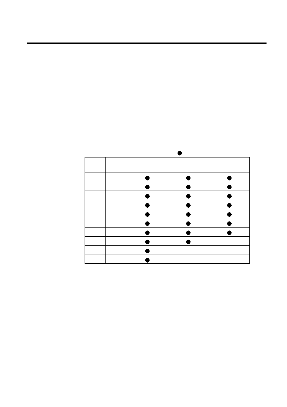
83
────────────────────────────────────────────────────
:RANGe
Sets the test range.
■
Syntax
<data>
:RANGe <data>
Numerical data in NR1 format
1to10
Function
Sets the test range.
・
・ The numerical value can be in NRf format, but any digits after the decimal point
will be rounded.
・ If this command is executed, the setting of the :RANGe:AUTO command is
automatically changed to OFF.
・ The numerical value corresponding to the test range and frequency which can be
set is as follows.
Range
number
1
2
3
4
Range
(Ω)
0.1
10
100
: settable / ---: cannot be set
to 100.0 kHz
1
100.1 kHz to
1.000 MHz
1.001 MHz to
5.000 MHz
Example
Transmission
The test range is set to 1 kΩ.
Error
If <data> is other than numerical value described above, an execution error
occurs.
Executing this command while the open or short circuit compensation is
performed generates an execution error.
5
6
7
8
9
10
For 3532-50 If the test frequency is greater than 100 kHz, the range
1k
10 k
100 k
1M ---
10 M --- ---
100 M --- ---
number 9 (10 MΩrange) cannot be set. If the test
frequency is greater than 1 MHz, the range number 8
(1 MΩrange) cannot be set.
:RANGe 5
────────────────────────────────────────────────────
:RANGe
Page 90

84
────────────────────────────────────────────────────
:RANGe?
Queries the test range.
■
Syntax
Function
:RANGe?
Returns the test range setting as numerical value (1 to 10) in NR1 format.
The numerical value corresponding to the test range and frequency which can be
set is as follows.
Range
number
1 0.1
2 1
3 10
4 100
5 1k
6 10 k
7 100 k
8 1M
9 10 M
10 100 M
Range (Ω)
Example
Response
If headers are on
If headers are off
The test range has been set to range 5 (1 kΩ).
Error
If the response message is longer than 300 bytes, a query error is generated.
:RANGE 5
5
────────────────────────────────────────────────────
:RANGe?
Page 91

85
────────────────────────────────────────────────────
:RANG e:AUTO
Enables and disables the auto-range function.
■
Syntax
<data>
Function
Example
Error
:RANGe:AUTO <data>
ON/OFF (character data)
Switches between automatic and manual setting of test range.
ON Switches the automatic setting.
OFF Switches the manual setting.
Transmission
The test range is switched to automatic selection (auto-ranging).
If <data> is other than character data described above, an execution error occurs.
Executing this command while the open or short circuit compensation is
performed generates an execution error.
:RANGe:AUTO?
■
Queries the auto-range function enablement.
:RANGe:AUTO ON
Syntax
Function
Examples
Error
:RANGe:AUTO?
Returns whether the test range is automatically set as character data.
ON, OFF
Response
If headers are on
If headers are off
If the response message is longer than 300 bytes, a query error is generated.
:RANGE:AUTO ON
ON
────────────────────────────────────────────────────
:RANGe:AUTO
Page 92

86
────────────────────────────────────────────────────
:SAVE
Saves the test conditions in specified panel number.
■
Syntax
<data>
:SAVE <number>, <name>
<number> Numerical data in NR1 format between 1 and 30
<name> Character data, up to 20 characters
Function
Saves the test conditions in specified panel number with name to be saved.
・
・ The numerical value can be in NRf format, but any digits after the decimal point
will be rounded.
・ The capital letters, numbers, and hyphen can be used.
・ If 21 or more characters are entered, the first 20 characters are used.
Example
Transmission :SAVE 3,TEST1
The test condition is saved as a name "TEST1" in panel number 3.
Error
If <data> is other than numerical value and character data described above, an
execution error occurs.
Executing this command while the open or short circuit compensation is
performed generates an execution error.
:SAVE?
Queries the panel number saved.
■
Syntax
<data>
Function
:SAVE? <data>
Numerical data in NR1 format between 0 and 30
Returns 1 when the test conditions are saved in specified panel number, and
・
returns 0 when not saved.
・ The numerical value can be in NRf format, but any digits after the decimal point
will be rounded.
・ The response message has no headers.
Example
Transmission :SAVE? 3
Response 1
The test condition is saved in panel number 3.
Error
If <data> is other than numerical value and character data described above, an
execution error occurs.
────────────────────────────────────────────────────
:SAVE
Page 93

87
────────────────────────────────────────────────────
:SCALe
Enables and disables the scaling function.
■
Syntax
<data>
Function
Example
Error
:SCALe <data>
ON/OFF
Enables and disables the scaling function.
Transmission :SCALe ON
Enables the scaling function.
If <data> is other than character data described above, an execution error occurs.
Executing this command while the open or short circuit compensation is
performed generates an execution error
:SCALe?
Queries the scaling function.
■
Syntax
Function
:SCALe?
Returns the setting of scaling function enablement as character data.
.
ON, OFF
Example
Error
Response
If headers are on
If headers are off
If the response message is longer than 300 bytes, a query error occurs.
:SCALE ON
ON
────────────────────────────────────────────────────
:SCALe
Page 94

88
────────────────────────────────────────────────────
:SCALe:FVALue
Sets the first parameters (a and b) in the scaling function.
■
Syntax
<data>
Function
Example
Error
:SCALe:FVALue <a>, <b>
Numerical data in NR3 format
Sets the first parameters (a and b values) in the scaling function.
・
・ For calculation equation of the scaling function, see the Instruction Manual of
main unit.
Transmission :SCALe:FVALue 2.0000E+00,1.0000E+00
Sets a value to 2.0000, and b value to 1.0000.
If <data> is other than numerical data described above, an execution error occurs.
Executing this command while the open or short circuit compensation is
performed generates an execution error
:SCALe:FVALue?
Queries the first parameters (a and b) in the scaling function.
■
Syntax
:SCALe:FVALue?
.
Function
Example
Error
Returns the setting of the first parameters (a and b values) in the scaling function
as a numerical value in NR3 format.
Response
If headers are on
If headers are off
If the response message is longer than 300 bytes, a query error occurs.
:SCALE:FVALUE 2.0000E+00,1.0000E+00
2.0000E+00,1.0000E+00
────────────────────────────────────────────────────
:SCALe:FVALue
Page 95

89
────────────────────────────────────────────────────
:SCALe:SVALue
Sets the second parameters (a and b) in the scaling function.
■
Syntax
<data>
Function
Example
Error
:SCALe:SVALue <a>, <b>
Numerical data in NR3 format
Sets the second parameters (a and b values) in the scaling function.
・
・ For calculation equation of the scaling function, see the Instruction Manual of
main unit.
Transmission :SCALe:SVALue 2.0000E+00,1.0000E+00
Sets a value to 2.0000, and b value to 1.0000.
If <data> is other than numerical data described above, an execution error occurs.
Executing this command while the open or short circuit compensation is
performed generates an execution error.
:SCALe:SVALue?
Queries the second parameters (a and b) in the scaling function.
■
Syntax
:SCALe:SVALue?
Function
Example
Error
Returns the setting of the second parameters (a and b values) in the scaling
function as a numerical value in NR3 format.
Response
If headers are on
If headers are off
If the response message is longer than 300 bytes, a query error occurs.
:SCALE:SVALUE 2.0000E+00,1.0000E+00
2.0000E+00,1.0000E+00
────────────────────────────────────────────────────
:SCALe:SVALue
Page 96

90
────────────────────────────────────────────────────
:SPEEd
Sets the testing speed.
■
Syntax
<data>
Function
Example
Error
:SPEEd <data>
FAST/NORMal/SLOW/SLOW2 (character data)
Sets the testing speed.
Transmission
If <data> is other than character data described above, an execution error occurs.
Executing this command while the open or short circuit compensation is
performed generates an execution error.
:SPEEd?
Queries the testing speed.
■
Syntax
Function
:SPEEd?
Returns the setting of testing speed as character data.
FAST, NORMAL, SLOW, SLOW2
:SPEEd NORMal
Example
Error
Response
If headers are on
If headers are off
If the response message is longer than 300 bytes, a query error is generated.
:SPEED NORMAL
NORMAL
────────────────────────────────────────────────────
:SPEEd
Page 97

91
────────────────────────────────────────────────────
:TRANsmit:TERMinator
Sets the data terminator for response messages.
■
Syntax
<data>
Function
Example
Error
:TRANsmit:TERMinator <data>
Numerical data in NR1 format between 0 and 255
Sets the data terminator for response messages.
・
・ The numerical value can be in NRf format, but any digits after the decimal point
will be rounded.
If <data> = 0, the terminator is set to LF (line feed) + EOI signal.
If <data> = 1 through 255, the terminator is set to CR (carriage return) + LF and
EOI signal.
・ When powering on, <data> is initially set to 0 (LF+EOI).
Transmission
The data terminator is set to LF + EOI
If <data> is other than numerical value described above, an execution error
occurs.
:TRANsmit:TERMinator?
:TRANsmit:TERMinator 0
Queries the data terminator for response messages.
■
Syntax
Function
Example
Error
:TRANsmit:TERMinator?
Returns the data terminator for response messages as a numerical value (0 or 1) in
NR1 format.
If <data> = 0, the terminator is LF and EOI signal.
If <data> = 1, the terminator is CR + LF and EOI signal
Response
If headers are on
If headers are off
If the response message is longer than 300 bytes, a query error is generated.
:TRANSMIT:TERMINATOR 0
0
────────────────────────────────────────────────────
:TRANsmit:TERMinator
Page 98

92
────────────────────────────────────────────────────
:TRIGger
Sets the type of trigger.
■
Syntax
<data>
Function
Example
Error
:TRIGger <data>
INTernal/EXTernal (character data)
Sets the type of trigger.
INTernal Internal trigger mode
EXTernal External trigger mode
Transmission
The trigger mode is set to internal trigger.
If <data> is other than character data described above, an execution error occurs.
Executing this command while the open or short circuit compensation is
performed generates an execution error.
:TRIGger?
Queries the trigger setting.
■
:TRIGger INTernal
Syntax
Function
Example
Error
:TRIGger?
Returns the trigger setting as character data.
INTERNAL/EXTERNAL
Response
If headers are on
If headers are off
The trigger mode has been set to internal triggering.
If the response message is longer than 300 bytes, a query error is generated.
:TRIGGER INTERNAL
INTERNAL
────────────────────────────────────────────────────
:TRIGger
Page 99

93
────────────────────────────────────────────────────
:TRIGger:DELA y
Sets the trigger delay time.
■
Syntax
<data>
Function
Example
Error
:TRIGger:DELAy <data>
Numerical data in NR2 format from 0.00 to 9.99.
Sets the trigger delay time.
・
・ The numerical value can be in NRf format, but rounding is performed for figures
beyond the last valid decimal place.
Transmission :TRIGger:DELAy 0.05
The trigger delay time is set to 50 ms.
If <data> is other than numerical value described above, an execution error
occurs.
Executing this command while the open or short circuit compensation is
performed generates an execution error.
:TRIGger:DELA y?
Queries the trigger delay time.
■
Syntax
Function
Example
Error
:TRIGger:DELAy?
Returns the current setting of trigger delay time as a numerical value in NR2
format from 0.00 to 9.99.
Response
If headers are on
If headers are off
The trigger delay time has been set to 50 ms.
If the response message is longer than 300 bytes, a query error is generated.
:TRIGGER:DELAY 0.05
0.05
────────────────────────────────────────────────────
:TRIGger:DELAy
Page 100

94
1 2
1 2
────────────────────────────────────────────────────
5.5 Response Format for Queries as Numerical Value
(1)Testvalue
1. The response formats for |Z| (impedance),|Y| (admittance), Cs (static capacitance in
series equivalent circuit mode), Cp (static capacitance in parallel equivalent circuit
mode), Ls (inductance in series equivalent circuit mode), Lp (inductance in parallel
equivalent circuit mode), Rs (effective resistance in series equivalent circuit mode),
G (conductance), Rp (effective resistance in parallel equivalent circuit mode), X
(reactan ce), B (susceptance) are as follows. (in NR3 format)
□.□□□□E±□□
1 Mantissa Five digits and decimal point
2 Exponent Two digits
When the value is overflow or underflow, the following value is displayed.
Overflow 99999E+99
Underflow -99999E+99
2. The response formats (in NR2 format) for θ(phase angle).
(-)
□□□.□□
(-)
□□.□□
(-)□.
□□
1 Sign Only when the value is negative, minus (-) is prefixed.
2 Numerical Up to the second decimal point
When the value is overflow or underflow, the following value is displayed.
Overflow 999.9
Underflow -999.9
3. The response formats (in NR2 format) for D (loss coefficient)
□.□□□□□
Up to the fifth decimal point
When the value is overflow or underflow, the following value is displayed.
Overflow 999999
Underflow -999999
4. The response formats (in NR2 format) for Q (Q factor)
────────────────────────────────────────────────────
□.□□
□□.□□
□□□.□□
Up to the second decimal point
When the value is overflow or underflow, the following value is displayed.
Overflow 9999
Underflow -9999
 Loading...