

Page 1

取扱説明書
X
Instruction Manual
9277
9278
ユニバーサルクランプオン CT
UNIVERSAL CLAMP ON CT
January 2009 Revised edition 8 9277A981-08 09-01H
2009 年 1 月 発行 改訂 8 版
Page 2

Page 3

目 次
はじめに
点検
使用前の確認
安全について
ご使用にあたっての注意
1
第 1 章概要
1.1
製品の概要
1.2
各部の名称
7
第 2 章測定方法
2.1
測定方法
2.2
消磁について
9
第 3 章仕様
第 4 章 保守・サービス
4.1
本器のクリーニング
4.2
サービス
12
13
17
17
17
1
1
2
5
7
8
9
Page 4

Page 5

__________________________________________________
1
はじめに
このたびは、
オンCTをご選定いただき、誠にありがとうございま
す。この製品を十分にご活用いただき、末長くご使用い
ただくためにも、取扱説明書はていねいに扱い、いつも
お手元に置いてご使用ください。
点検
本器がお手元に届きましたら、輸送中において異常また
は破損がないかを点検してからご使用ください。
特に付属品に注意してください。
万一、破損あるいは仕様どおり動作しない場合は、お買
上店(代理店)または最寄りの営業所にご連絡ください。
使用前の確認
・使用前には、保存や輸送による故障がないか、点検と
動作確認をしてから使用してください。故障を確認
した場合は、お買上店(代理店)か最寄りの営業所に
ご連絡ください。
・ケーブルの被覆が破れたり、金属が露出していない
か、使用する前に確認してください。損傷がある場合
は、感電事故になるので、お買上店(代理店)か最寄
りの営業所にご連絡ください。
HIOKI9277, 9278
ユニバーサルクランプ
_____________________________________________
Page 6

2
危
警
__________________________________________________
安全について
危険
この機器は
IEC 61010
験し、安全な状態で出荷されています。測定方法を間違え
ると人身事故や機器の故障につながる可能性があります。
取扱説明書を熟読し、十分に内容を理解してから操作して
ください。万一事故があっても、弊社製品が原因である場
合以外は責任を負いかねます。
安全記号
この取扱説明書には本器を安全に操作し、安全な状態に
保つのに要する情報や注意事項が記載されています。
本器を使用する前に下記の安全に関する事項をよくお
読みください。
・使用者は、機器上に表示されている マークのところ
について、取扱説明書の
機器の操作をしてください。
・使用者は、取扱説明書内の
必ず読み注意する必要があることを示します。
直流(DC)と交流(AC)の両用を示します。
絶縁保護具(電気用ゴム手袋、電気用ゴム長靴、安全帽等)
を着用して、活線状態の電路に着脱できることを示します。
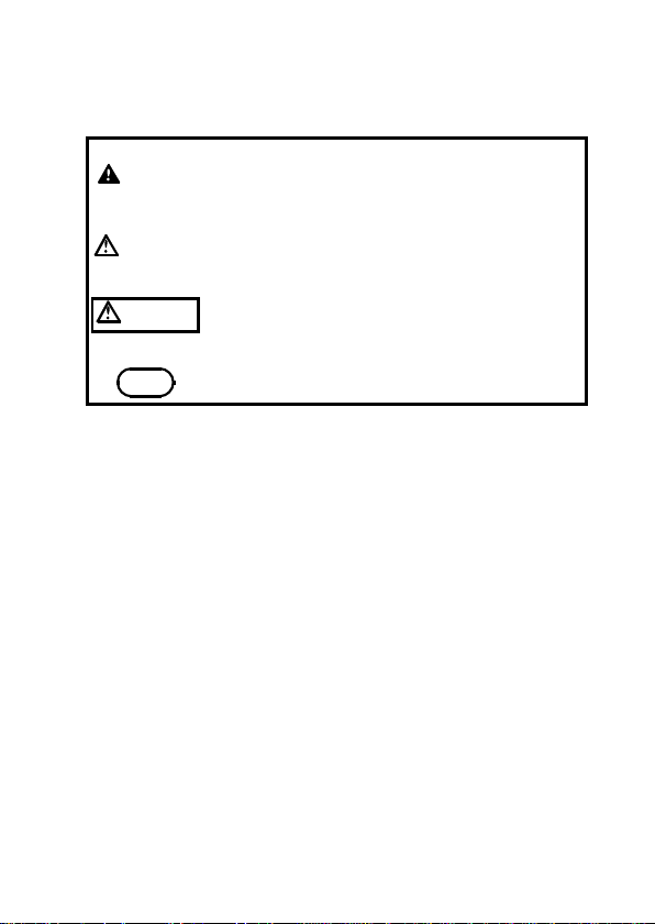
取扱説明書の注意事項には、重要度に応じて以下の
表記がされています。
安全規格に従って、設計され、試
マークの該当箇所を参照し、
マークのあるところは、
操作や取扱いを誤ると、使用者が死亡または重傷に
険
つながる危険性が極めて高いことを意味します。
操作や取扱いを誤ると、使用者が死亡または重傷に
告
つながる可能性があることを意味します。
操作や取扱いを誤ると、使用者が傷害を負う場合、
注意
または機器を損傷する可能性があることを意味します。
注記
_____________________________________________
製品性能および操作上でのアドバイス的なことを
意味します。
Page 7

__________________________________________________
3
測定カテゴリ(過電圧カテゴリ)について
本器は
CATII (600V)、CATIII (300V)
測定器を安全に使用するため、
ゴリとして、使用する場所により安全レベルの基準を
CATⅠ〜CAT
Ⅳで分類しています。概要は下記のよう
になります。
CAT I:
CAT II:
CAT III:
CAT IV:
コンセントからトランスなどを経由した機器内
の二次側の電気回路
コンセントに接続する電源コード付き機器(可
搬形工具・家庭用電気製品など)の一次側電路
直接分電盤から電気を取り込む機器(固定設
備)の一次側および分電盤からコンセントまで
の電路
建造物への引込み電路、引込み口から電力量メ
ータおよび一次側電流保護装置(分電盤)まで
の電路
数値の大きいカテゴリは、より高い瞬時的なエネルギー
のある電気環境を示します。そのため、
れた測定器は、
Ⅱで設計されたものより高い瞬時的
CAT
なエネルギーに耐えることができます。
カテゴリの数値の小さいクラスの測定器で、数値の大き
いクラスに該当する場所を測定すると重大な事故につ
ながる恐れがありますので、絶対に避けてください。
特に、
Ⅰの測定器を
CAT
CAT
場所の測定に用いないでください。
測定カテゴリは
IEC60664
の過電圧カテゴリに対応し
ます。
に適合しています。
IEC61010
では測定カテ
Ⅲで設計さ
CAT
Ⅱ、ⅢおよびⅣに該当する
_____________________________________________
Page 8

4
__________________________________________________
確度について
弊社では測定値の限界誤差を、次に示す
ール)、
(リーディング)に対する値として定義して
rdg.
います。
(最大表示値、目盛長)
f.s.
最大表示値または、目盛長を表します。
一般的には、現在使用中のレンジを表します。
(読み値、表示値、指示値)
rdg.
現在測定中の値、測定器が現在指示している値を
表します。
(フルスケ
f.s.
_____________________________________________
Page 9

__________________________________________________
5
ご使用にあたっての注意
本器を安全にご使用いただくために、また機能を十二分
にご活用いただくために、下記の注意事項をお守りくだ
さい。
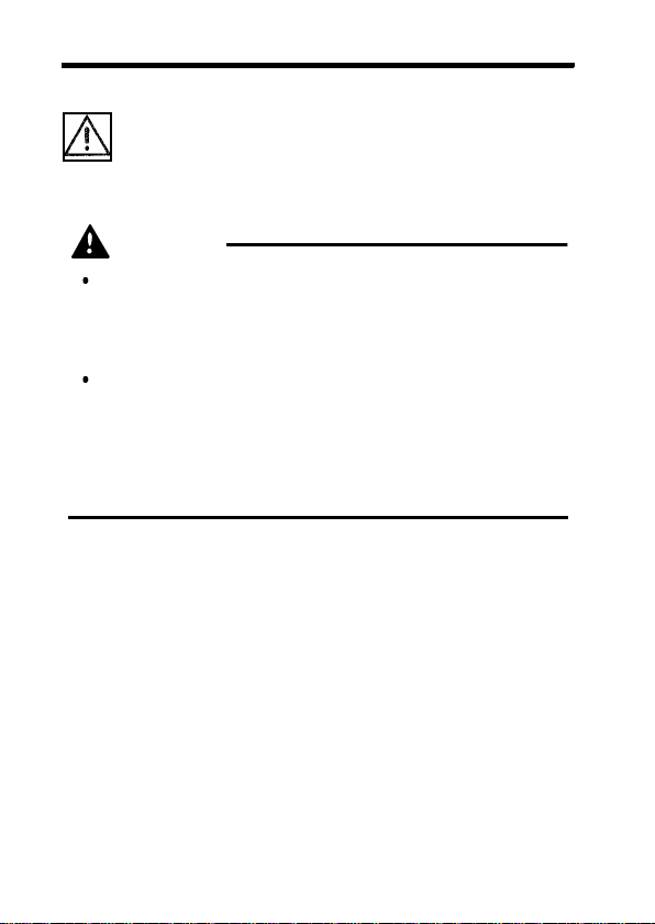
危険
・短絡事故や人身事故を避けるため、ユニバーサルクランプ
オンCTは
以下の電路で使用してください。また裸導体には使用しな
いでください。
・ユニバーサルクランプオンCTは必ずブレーカの2次側に
接続してください。ブレーカの2次側は、万一短絡があっ
ても、ブレーカにて保護します。1次側は、電流量が大き
く、万一短絡事故が発生した場合、損傷が大きくなるので
測定しないでください。
AC600 V(CATII
警告
・本器をぬらしたり、ぬれた手で測定しないでください。感
電事故の原因になります。
・活線で測定するので、感電事故を防ぐため、労働安全衛生
規則に定められているように、電気用ゴム手袋、電気用ゴ
ム長靴、安全帽等の絶縁保護具を着用してください。
)または
AC300 V(CATIII
)
_____________________________________________
Page 10

6
__________________________________________________
注意
・測定範囲を超える電流を長時間入力しないでください。本
器を破損する恐れがあります。
・直射日光や高温、多湿、結露するような環境下での、保存
や使用はしないでください。変形、絶縁劣化を起こし、仕
様を満足しなくなります。
・本器の損傷を防ぐため、運搬および取扱いの際は振動、衝
撃を避けてください。特に、落下などによる衝撃に注意し
てください。本器を破損します。
・コア部つき合わせ面にゴミなどが付着した場合は、測定に
影響がでますので柔らかい布で軽くふき取ってください。
・コード類の被覆に損傷を与えないため、踏んだり挟んだり
しないでください。
・コードが溶けると金属部が露出し危険です。発熱部等に触
れないようにしてください。
・断線による故障を防ぐため、ケーブル を折ったり引っ張っ
たりしないでください。
・この機器は室内用に設計されています。安全性を損なわな
いで0℃〜40℃の温度まで使用できます。
・高周波大電流を測定するとき、コアが発熱する場合があり
ます。最大許容入力範囲を超えないように注意してくださ
い。(「第3章 仕様」のグラフをご参照ください)
注記
トランスや大電流路など強磁界の発生している近く、
また無線機など強電界の発生している近くでは、正確
な測定ができない場合があります。
_____________________________________________
Page 11

__________________________________________________
7
第1章概要
製品の概要
1.1
本器は
20 A(9277)、200 A(9278
流対応のセンサとして開発され、電力ラインを切り離す
ことなく、活線の状態で交流・直流電流を測定できま
す。
また、良好な周波数特性(振幅、位相)、良好な温度特性
(感度、オフセット)、耐電圧を有しており、操作、接続
が簡単であるので、多方面での電流、電力測定にご使用
いただけます。
)定格の
AC/DC
電
_____________________________________________
第1章概要
Page 12

8
__________________________________________________
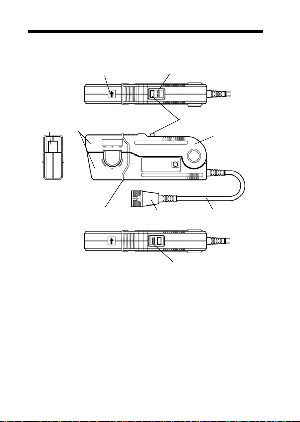
各部の名称
1.2
レバー
クランプ部
センサヘッド部
電流方向表示マーク
バリア
"LOCK"
出力コネクタ
"UNLOCK"
表示
ツマミ
センサ部
ケーブル
表示
_____________________________________________
第1章概要
Page 13
__________________________________________________
9
第2章 測定方法
測定方法
2.1
注意
・断線防止のため、出力コネクタを引き抜くときは、差込部
分(ケーブル以外)を持って抜いてください。
・接続機器の電源が入った状態、または測定導体をクランプ
した状態で、コネクタの抜差しをしないでください。本体
およびセンサの故障の原因になります。
・連続最大入力範囲は測定時の自己発熱による温度上昇から
定めた値です。これを超える電流を入力しないでくださ
い。本器を損傷する恐れがあります。
・連続最大許容入力範囲は測定電流の周波数によって異なり
ます。 「第3章 仕様」のグラフをご参照ください。
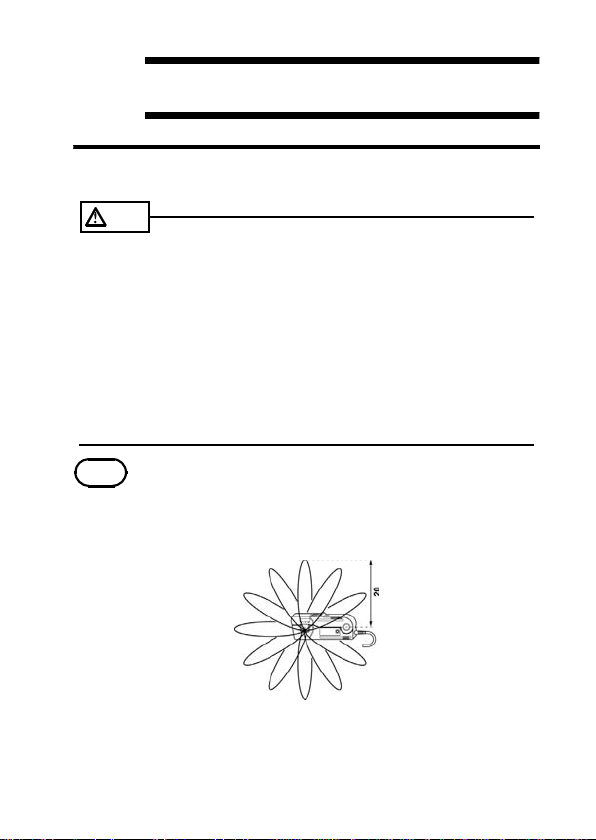
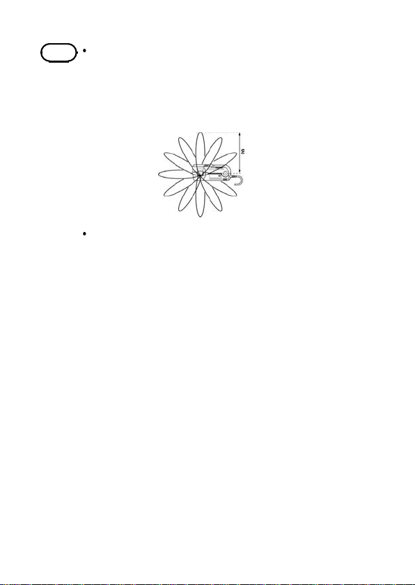
注記
・測定電流が小さい場合、導体を複数巻くことにより相
対的に感度をあげることができます。導体を10回巻
きした場合、測定電流の10倍の信号が出力されま
す。ただし、巻き線の直径は
なるようにしてください。
以上で放射状に
20 cm
・この製品の信号出力回路は直列に抵抗が挿入されてい
ます。そのため、出力信号を直接測定する場合は、入
力抵抗の十分大きな測定機器を使用するようにしてく
_____________________________________________
ださい。
第2章 測定方法
Page 14
10
__________________________________________________
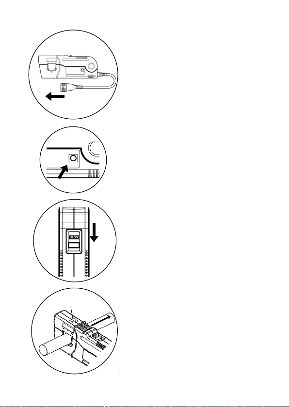
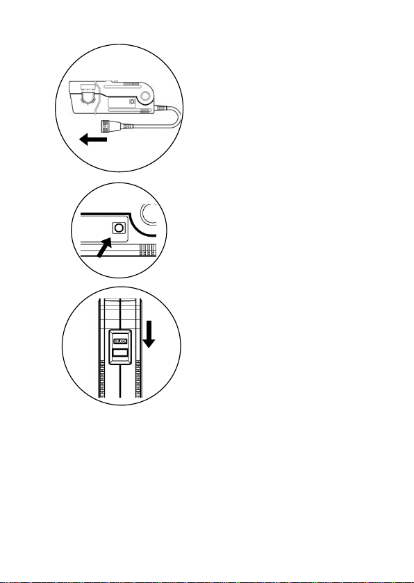
クランプ部が開いている場合は閉
1.
じます。
電流方向マーク電流方向マーク
電源側
負荷側
接続機器の電源が
2.
OFF
になってい
るか確認します。
クランプオンCTの出力コネクタを
3.
接続します。
接続機器の電源をONにします。
4.
5. DMAG
スイッチを押して消磁しま
す。(「
消磁について」をご覧く
2.2
ださい)
センサ部のツマミを引き、クラン
6.
プ部を開いてください。
センサ部先端に表示されている電
7.
流方向マークの矢印の方向が被測
定電流の流れる方向と一致するよ
うに被測定導体をクランプしてく
ださい。
被測定導体がクランプ窓部の中央
になるようにしてください。
_____________________________________________
第2章 測定方法
Page 15

__________________________________________________
注記
導体は必ず一本だけクランプしてください。単相(
本)・三相(3本)を同時にクランプして測定するこ
とはできません。
11
2
センサ部のツマミを
8.
現れるまで押し、レバーを確実にロ
ックします。
"LOCK"
表示が
_____________________________________________
第2章 測定方法
Page 16

12
__________________________________________________
消磁について
2.2
直流電流測定や交流電流測定時の突入電流などを測定
した後では、クランプに入力がない状態でも微小電圧が
出力されます。これは、クランプに用いているコアの特
性によるもので、コア内に磁気が残るためです。
この残留磁気は測定誤差になりますが、クランプに入力
がない状態で
磁気を取り去ることができます。
注記
・電源投入時、
・入力中に
ん。
・消磁はクランプ部が閉じた状態で行ってください。
・消磁動作は約3秒ほどかかります。
・クランプに過大な電流が入力された後、一回の消磁動
作で完全に残留磁気を取り除けない場合は、一度クラ
ンプを開けた状態で
閉じた状態で再度
・クランプを閉じる場合、突き合わせ面に衝撃が加わる
と、オフセットが出力される場合があります。この場
合、クランプに入力が無い状態で
押すと、正常状態に戻ります。
・直流電流測定の場合、連続最大許容入力以上の入力が
されると、誤動作する場合があります。この場合もク
ランプに入力がない状態で
正常状態に戻ります。
・正常に戻らない場合や、
残留磁気がとりきれない場合は、お買い上げ店(代理
店)か最寄の営業所にご連絡ください。
DMAG
スイッチを押すことにより、残留
DMAG
スイッチを一度押してください。
DMAG
スイッチを押しても消磁はできませ
スイッチを押し、さらに
DMAG
スイッチを押してください。
DMAG
スイッチを
DMAG
スイッチを押すと、
DMAG
スイッチを押しても
DMAG
_____________________________________________
第2章 測定方法
Page 17

__________________________________________________
13
第3章仕様
形名
定格電流(
出力電圧(
最大許容入力範囲
(DC〜
3kHz
入力抵抗(DC)
出力抵抗
基本確度
確度保証期間
振幅−周波数特性
(基本確度からの偏
差)
位相−周波数特性
温度係数
(0〜40℃にて)
使用温湿度範囲
保存温湿度範囲
導体位置の影響 ±
外部磁界の影響
(
400 A/m, 55 Hz
よびDCの磁界中)
耐電圧 電気回路−ケース間,電気回路−コア間
AC/DC
AC/DC
にて)
23℃±3
)
)
℃
お
_____________________________________________
9277 9278
20 A f.s. 200 A f.s.
2 V/20 A 2 V/200 A
50 Arms (75 Apeak) 350 Arms (500 Apeak)
Ω以下
0.05 m
Ω
50
および45〜
DC
分以上において消磁後
振幅:±
0.5% rdg.±0.05% f.s.
位相:±
年間
1
DC〜1 kHz
1k〜50 kHz
50 k〜100 kHz ±5.0%
DC〜1 kHz
1k〜50 kHz
50 k〜100 kHz ±5.0
感度:±
オフセット:±
0〜40℃,80%rh
-10〜50℃,80%rh
0.5%
Max. 0.2 A Max. 1 A
電気回路−クランプセンサ(窓部)
クランプセンサ(窓部)−ケース間
AC3536 Vrms/15
°以内(ただしDCは規定なし)
0.2
0.05% rdg./
以内(
、ウォーミングアップ
66 Hz
±
1.0%
±
2.5%
±
°以内
0.5
±
°以内
2.5
°以内
℃以内
0.005% f.s./
以下(結露しないこと)
以下(結露しないこと)
) ±
DC,55 Hz
秒間
0.002 m
以内
以内
以内
℃以内
1.5%
Ω以下
以内(
30
DC,55 Hz
,
)
第3章仕様
Page 18

14
__________________________________________________
形名
対地間最大定格
電圧
測定可能導体 φ
使用場所 高度
電源電圧 ±
電源容量(±
消費電力
外形寸法・質量 約
ケーブル長 約
付属品
適合規格 安全性
製品保証期間
12 V
時) ±
EMC
9277 9278
600 V CAT II, 300 V CATIII
以下
20 mm
まで、屋内
2,000 m
12 V〜±15 V
キング)
150 mA
Max. 3.6W.
時)
176 W×69 H×27 D mm
約
470 g
3m
携帯用ケース
9375
取扱説明書
マークバンド
EN61010
測定カテゴリ
4000 V),
EN61326
年間
1
(確度保証内、ただしトラッ
(定格入力時) ±
(定格入力
個
1
1
6個(3
II, III
汚染度
部
(予想される過渡過電圧
2
(定格入力時)
250 mA
Max. 7.2W
時)
(定格入力
(突起物含まず)
組)
_____________________________________________
第3章仕様
Page 19

__________________________________________________
15
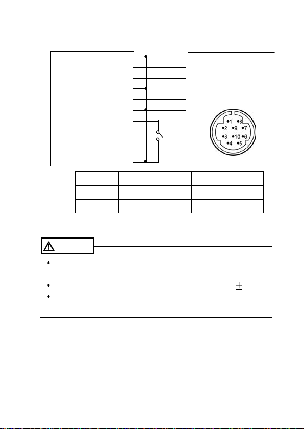
出力コネクタの結線例
電源
電源
電源
出力
出力
出力
消磁信号
識別信号
識別信号
シールド ⑩
適合レセプタクル
注意
・使用電源の容量は、±とも
①
GND
②
(+)
③
(-)
④
(-)
⑤
(+)
⑥
(-)
⑦
ID3
⑧
ID1
⑨
ID2
9277 9278
ID1 GND
ID2 N.C GND
GND
+12 V (〜+15 V) [0.5 A以上]
-12 V (〜-15 V) [0.5 A以上]
Vout (2 V f.s./
GND
出力コネクタのピン配列
に接続
GND
RM515ERB-10SD
以上必要です。
0.5 A
定格入力
に接続
に接続
(ヒロセ)
)
・電源電圧の接続を間違えると、内部回路が破壊される場合
がありますので注意してください。
・消磁は、⑦ピンを
と短絡後、開放することで動作し
GND
ます。
_____________________________________________
第3章仕様
Page 20

16
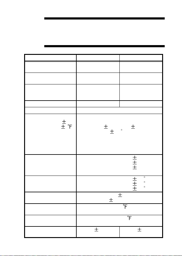
__________________________________________________
流
電
力
入
周波数
最大許容入力範囲(連続)
9277
流
電
力
入
周波数
最大許容入力範囲(連続)
9278
_____________________________________________
第3章仕様
Page 21

__________________________________________________
17
第4章 保守・サービス
本器のクリーニング
4.1
本器の汚れをとるときは、柔らかい布に水か中性洗剤を
少量含ませて、軽くふいてください。ベンジン、アルコ
ール、アセトン、エーテル、ケトン、シンナー、ガソリ
ン系を含む洗剤は絶対に使用しないでください。変形、
変色することがあります。
サービス
4.2
・故障と思われるときは、お買上店(代理店)か最寄り
の営業所にご連絡ください。輸送中に破損しないよ
うに梱包し、故障内容も書き添えてください。輸送中
の破損については保証しかねます。
・本器の確度維持あるいは確認には、定期的な校正が必
要です。
修理・校正業務のご用命は、「日置エンジニアリング
サービス(株)」までお願いいたします。
(
TEL 0268-28-0823、FAX 0268-28-0824
)
_____________________________________________
第4章 保守・サービス
Page 22

18
__________________________________________________
_____________________________________________
第4章 保守・サービス
Page 23

保 証 書
形名
9277, 9278
本製品は、弊社の厳密なる検査を経て合格した製品をお届けした物です。
万一ご使用中に故障が発生した場合は、お買い求め先にご連絡ください。
本書の記載内容で無償修理をさせていただきます。また、製品の使用による損失について
は、購入金額までの支払いとさせていただきます。なお、保証期間は購入日より1年間で
す。購入日が不明の場合は、製品の製造月から1年を目安とします。 ご連絡の際は、本書
を提示してください。また、確度については、明示された確度保証期間によります。
お客様 ご住所: 〒
*お客様へのお願い
・保証書の再発行はいたしませんので、大切に保管してください。
・「形名、製造番号、購入日」およびお客様「ご住所、ご芳名」は恐れ入りますが、お
客様にて記入していただきますようお願いいたします。
1.取扱説明書・本体注意ラベル(刻印を含む)などの注意事項にしたがった正常な使用
状態で保証期間内に故障した場合には、無償修理いたします。また、製造後一定期間
を経過したものおよび部品の生産中止、不測の事態の発生などにより修理不可能と
なった場合は、修理、校正などを辞退する場合がございます。
2.保証期間内でも、次の場合には保証の対象外とさせていただきます。
−1.製品を使用した結果生じる被測定物の、二次的、三次的な損傷、被害
−2.製品の測定結果がもたらす二次的、三次的な損傷、被害
−3.取扱説明書に基づかない不適当な取り扱い、または使用による故障
−4.弊社以外による修理や改造による故障および損傷
−5.取扱説明書に明示されたものを含む、部品の消耗
−6.お買い上げ後の輸送、落下などによる故障および損傷
−7.外観上の変化(筐体のキズなど)
−8.火災、風水害、地震、落雷、電源異常(電圧、周波数など)、戦争・暴動行為、
−9.保証書の提出が無い場合
−10.その他弊社の責任とみなされない故障
−11.特殊な用途(宇宙用機器、航空用機器、原子力用機器、生命に関わる医療用
3.本保証書は日本国内のみ有効です。(
サービス記録
年月日 サービス内容
製造番号 保証期間
ご芳名:
放射能汚染およびその他天災地変などの不可抗力による故障および損傷
機器及び車輌制御機器など)に組み込んで使用する場合で、前もってその旨
を連絡いただかない場合
購入日 年 月より1年間
This warranty is valid only in Japan.)
〒
TEL 0268-28-0555
FAX 0268-28-0559
386-1192
長野県上田市小泉81
06-03
Page 24

Page 25

9277, 9278
UNIVERSAL
CLAMP ON CT
INSTRUCTION MANUAL
Page 26

Page 27

Contents
Introduction 1
Inspection
Preliminary Checks
Safety Notes
Notes on Use
Chapter 1 Overview 9
1.1 Product Overview 9
1.2 Names of Parts
Chapter 2 Measurement Procedure 11
2.1 Measurement Procedure 11
2.2 Demagnetizing (DMAG)
Chapter 3 Specification 17
10
15
1
1
2
6
Chapter 4 Maintenance and Service
4.1 Maintenance 21
4.2 Service
21
21
Page 28

Page 29

__________________________________________________
1
Introduction
Thank you for purchasing the HIOKI "9277,9278
UNIVERSAL CLAMP ON CT". To obtain
maximum performance from the product, please
read this manual first, and keep it handy for
future reference.
Inspection
When you receive the product, inspect it
carefully to ensure that no damage occurred
during shipping. In particular, check the
accessories. If damage is evident, or if it fails to
operate according to the specifications, contact
your dealer or Hioki representative.
Preliminary Checks
Before using the product the first time, verify
that it operates normally to ensure that the no
damage occurred during storage or shipping.
If you find any damage, contact your dealer
or Hioki representative.
Before using the product, make sure that the
insulation on the cables is undamaged and
that no bare conductors are improperly
exposed. Using the product in such
conditions could cause an electric shock, so
contact your dealer or Hioki representative for
_____________________________________________
repair.
Page 30

2
__________________________________________________
Safety Notes
DANGE R
This product is designed to conform to IEC
61010 Safety Standards, and has been
thoroughly tested for safety prior to shipment.
However, mishandling during use could result
in injury or death, as well as damage to the
product. Be certain that you understand the
instructions and precautions in the manual
before use. We disclaim any responsibility for
accidents or injuries not resulting directly from
product defects.
Safety symbols
This manual contains information and warnings
essential for safe operation of the product and
for maintaining it in safe operating condition.
Before using the product, be sure to carefully
read the following safety notes.
The symbol printed on the product indicates
that the user should refer to a corresponding
topic in the manual (marked with the
before using the relevant function.
In the manual, the symbol indicates
particularly important information that the user
should read before using the product.
symbol)
Indicates both DC (Direct Current) and AC
(Alternating Current).
Wear appropriate protective insulation (insulating
rubber gloves and boots, helmet and etc.) when
connecting and disconnecting from live electric
circuits.
_____________________________________________
Page 31
__________________________________________________
3
The following symbols in this manual indicate
the relative importance of cautions and
warnings.
DANGER
WARNING
CAUTION
NOTE
Indicates that incorrect operation presents an
extreme hazard that could result in serious
injury or death to the user.
Indicates that incorrect operation presents a
significant hazard that could result in serious
injury or death to the user.
Indicates that incorrect operation presents a
possibility of injury to the user or damage to
the product.
Advisory items related to performance or
correct operation of the product.
_____________________________________________
Page 32

4
__________________________________________________
Measurement categories (Overvoltage categories)
This product complies with CATII (600V), CATIII
(300V) safety requirements.To ensure safe
operation of m easurement products, IEC 61010
establishes safety standards for various
electrical environments, categorized as CAT I to
CAT IV, and called measurement categories.
These are defined as follows.
CAT I:
CAT II: Primary electrical circuits in equipment
CAT III: Primary electrical circuits of heavy
CAT IV: The circuit from the service drop to the
Secondary electrical circuits connected
to an AC electrical outlet through a
transformer or similar device.
connected to an AC electrical outlet by a
power cord (portable tools, household
appliances, etc.)
equipment (fixed installations) connected
directly to the distribution panel, and
feeders from the distribution panel to
outlets.
service entrance, and to the power
meter and primary overcurrent protection
device (distribution panel).
Higher-numbered categories correspond to
electrical environments with greater momentary
energy. So a measurement device designed for
CAT III environments can endure greater
momentary energy than a device designed for
CAT II. Using a measurement product in an
environment designated with a higher-numbered
category than that for which the product is rated
could result in a severe accident, and must be
carefully avoided.Never use a CAT I measuring
product in CAT II, III, or IV envir o nments.
_____________________________________________
Page 33

__________________________________________________
The measurement categories comply with the
Overvoltage Categories of the IEC60664
Standards.
5
Accuracy
We define measurement tolerances in terms of
f.s. (full scale), rdg. (reading) and dgt. (digit)
values, with the following meanings:
f.s. (maximum display value or scale length)
The maximum displayable value or the full length
of the scale.
This is usually the maximum value of the currently
selected range.
rdg. (reading or displayed value)
The value currently being measured and indicated
on the measuring instrument.
_____________________________________________
Page 34
6
__________________________________________________
Notes on Use
Follow these precautions to ensure safe
operation and to obtain the full benefits of the
various functions.
DANGE R
To avoid short circuits and potentially lifethreatening hazards, never attach the
UNIVERSAL CLAMP ON CT to a circuit that
operates at more than the 600 VAC(CATII) or 300
VAC(CATIII), or over bare conductors.
UNIVERSAL CLAMP ON CT should only be
connected to the secondary side of a breaker,
so the breaker can prevent an accident if a
short circuit occurs. Connections should never
be made to the primary side of a breaker,
because unrestricted current flow could cause a
serious accident if a short circuit occurs.
_____________________________________________
Page 35

__________________________________________________
7
WARNING
To avoid electric shock, do not allow the
product to get wet, and do not use it when your
hands are wet.
To avoid electric shock when measuring live lines,
wear appropriate protective gear, such as insulated
rubber gloves, boots and a safety helmet.
CAUTION
Note that the product may be damaged if current
exceeding the selected measurement range is
applied for a long time.
Do not store or use the product where it could be
exposed to direct sunlight, high temperature or
humidity, or condensation. Under such conditions,
the instrument may be damaged and insulation may
deteriorate so that it no longer meets specifications.
To avoid damage to the product, protect it from
vibration or shock during transport and handling,
and be especially careful to avoid dropping.
Measurements are degraded by dirt on the mating
surfaces of the clamp-on CT, so keep the surfaces
clean by gently wiping with a soft cloth.
_____________________________________________
Page 36

8
__________________________________________________
CAUTION
Avoid stepping on or pinching the cable, which
could damage the cable insulation.
Keep the cables well away from heat sources, as
bare conductors could be exposed if the insulation
melts.
To avoid damaging the cables,do not bend or pull
the cables.
This product is designed for indoor use, and
operates reliably from 0 to 40 .
When measuring the high-frequency large current,
over-heating of the core may occur. Note that the
input never exceed the maximum permissible input
range. See the figures in Chapter 3,"Specifications".
NOTE
Accurate measurement may be impossible in
the presence of strong magnetic fields, such
as near transformers and high-current
conductors, or in the presence of strong
electromagnetic fields such as near radio
transmitters.
_____________________________________________
Page 37

__________________________________________________
9
Chapter 1
Overview
1.1 Product Overview
The 9277, 9278 was developed for to provide a
20 A (9277), 200 A (9278) clamp sensor
corresponding to AC/DC current.
The 9277, 9278 makes it possible to measure
AC/DC current in live power lines without c utting
into the lines. The sensor features good
frequency response (amplitude and phase),
good temperature response (sensitivity and
offset), and dielectric strength and is easy to
connect and use. Its versatility will find
application in a wide variety of fields dealing
with current and power measurement.
_____________________________________________
Chapter 1 Overview
Page 38
10
__________________________________________________
1.2 Names of Parts
Current direction indication
Lever
Clamp
Sensor head
Barrier
"LOCK" indication
Slider
Output connector
"UNLOCK" indication
Sensor
Cable
_____________________________________________
Chapter 1 Overview
Page 39

__________________________________________________
11
Chapter 2
Measurement Procedure
2.1 Measurement Procedure
CAUTION
To avoid damaging the output cable, grasp the
connector, not the cable, when unplugging the
cable.
To prevent damage to the product and sensor,
never connect or disconnect a sensor while the
power is on.
The maximum continuous input range is based on
heat that is internally generated during measurement.
Never input current in excess of this level. Exceeding
the rated level may result in damage to the cable.
The maximum continuous input range varies
according to the frequency of the current being
measured. See the figures in Chapter 3,
"Specifications"
_____________________________________________
Chapter 2 Measurement Procedure
Page 40
12
__________________________________________________
NOTE
To measure small current levels, multiple
windings may be used to increase the relative
sensitivity. 10 windings multiplies the
measured current by about a factor of 10.
However, in this case the diameter of the
winding should be 20 cm or more, and radial.
This product has a resistance in series with the
signal output circuits. Therefore, if measuring
an output signal directly, ensure that the input
resistance of the measuring instrument is
sufficiently high.
_____________________________________________
Chapter 2 Measurement Procedure
Page 41
__________________________________________________
1. Close the clamp jaws when
the clamp jaws are opened.
2. Make sure that the unit's
power switch is OFF.
3. Connect the clamp-on CT
connector to the unit.
4. Turning the power on the unit.
5. Press the DMAG switch to
magnetize.
(See 2.2 Demagnetizing
(DMAG))
6. Pull the sensor slider, so that
the clamp opens.
13
_____________________________________________
Chapter 2 Measurement Procedure
Page 42

14
__________________________________________________
NOTE
Current direction
indication
Load side
7. Align the sensor so that the
current direction indication
corresponds to the direction
of current flow through the
conductor to be measured,
and clamp so that the
Power
supply side
conductor is in the center of
the sensor aperture.
Make sure that only one conductor is in the
core. Single-phase (2-wire) and three-phase
(3-wire) lines clamped together will not produce
reading.
8. Press the slider on the sensor
head and hold it until LOCK
appears, and check that the
lever is firmly locked.
_____________________________________________
Chapter 2 Measurement Procedure
Page 43

__________________________________________________
15
2.2 Demagnetizing (DMAG)
After measuring rush current or similar of AC or
DC current measurement, micro voltage is
output even if there is no input on the clamp.
This is caused by the core characteristic using
the clamp and magnetic is remained in the
core. This remanent cause measuring error, but
it can be removed by pressing DMAG with no
input onto the clamp.
NOTE
_____________________________________________
After powering on, press DMAG.
It is possible to magnetize even if pressing
DMAG during input.
Always make sure that the clamp jaws are
completely closed during demagnetising.
Demagnetization occurs for about 3 seconds.
If an excessive amount of current was input so
that one attempt at demagnetization does not
completely rid of the remanence, open the
clamp jaws and press DMAG, then close the
clamps, and press DMAG again.
In case of closing the clamp and if the facing
surface of the core is subjected to shock,
offset maybe output. In this case, press the
DMAG switch with no input on the clamp.
When measuring DC current and applying
exceed continuous the maximum permissible
input, the malfunction may occur. Press the
DMAG switch with no input on the clamp, to
return to normal.
If it does not return to normal condition, or
even pressing DMAG, the magnetic is
remained in the core, contact your dealer or
Hioki representative.
Chapter 2 Measurement Procedure
Page 44

16
__________________________________________________
_____________________________________________
Chapter 2 Measurement Procedure
Page 45
__________________________________________________
17
Chapter 3
Specification
Model 9277 9278
Rated current
(AC/DC)
Output voltage
(AC/DC)
The maximum
permissible input
range (DC to 3 kHz)
Input resistance (DC) Max. 0.05 mΩ Max. 0.002 mΩ
Output resistance 50 Ω
Basic accuracy
Period of guaranteed
Amplitude-frequency
characteristic
(deviation from
accuracy)
Phase-frequency
characteristic
Temperature
coefficient
Operating temperature
and humidity range
Storage temperature
and humidity range
Effect of conductor
position
_____________________________________________
23
(73
accuracy
20 A f.s. 200 A f.s.
2 V/20 A 2 V/200 A
50 Arms
(75 Apeak)
DC and 45 Hz to 66 Hz, 30 min or
o
C
3
more warming-up after degaussing
5 )
Amplitude:
Phase: within
(DC has no provision)
1 year
DC to 1 kHz within 1.0%
1 k to 50 kHz within
50 k to 100 kHz within 5.0%
DC to 1 kHz within 0.5
1 k to 50 kHz within 2.5
50 k to 100 kHz within 5.0
Sensitivity: within 0.05% rdg. /
Offset: within
0to40
Max. 80%RH (no condensation)
-10 to 50
Max. 80%RH (no condensation)
Within 0.5%
(DC, 55 Hz)
0.5% rdg. 0.05% f.s.
0.2
o
0.005% f.s. /
C (32 to 104 ),
o
C (14 to 122 ),
Chapter 3 Specification
350 Arms
(500 Apeak)
2.5%
o
C
Within 1.5%
(DC, 55 Hz)
o
C
Page 46

18
__________________________________________________
Model 9277 9278
Effect of external
magnetic field (400
A/m, 55 Hz and DC)
Dielectric strength 3536 VrmsAC for 15 seconds.
Maximum rated
voltage to earth
Operating environment Indoor, <Height 2000 m (6562 feet)
Diameter of
measurable
conductors
Supply voltage 12 V to 15 V (with accuracy
Power supply
capacity
Supply consumption Max. 3.6 W
Dimensions and
mass
Cord length Approx. 3 m (9.84 feet)
Accessories 9375 CARRYING CASE 1
Standards Safety:
Max. 0.2 A Max. 1 A
(between case and clamp sensor
(aperture))
(between electric circuit and case,
between electric circuit and core,
between electric circuit and clamp
sensor (aperture)
600 V (CATII), 300 V (CATIII)
ASL
20 mm (0.79") or less
guaranty but tracking)
150 mA
(with rated input)
(with rated input)
Approx. 176W 69H 27D mm
(6.93"W
projections)
Approx. 470 g (16.6 oz.)
Instruction manual 1
Markband 6 (3 set)
EN61010-2-032:2002
Type B current sensor
Measurement category II, III,
Pollution Degree 2 (4000 V expected
EMC:
transient Overvoltage)
EN61326:1997+A1:1998+A2:2001
+A3:2003
2.72"H 1.06"D)(excluding
250 mA
(with rated input)
Max. 7.2 W
(with rated input)
_____________________________________________
Chapter 3 Specification
Page 47
__________________________________________________
19
Output connector pin array
Power supply
Power supply
Power supply
Output
Output
Output
Demagnetizing
signal
Identifying signal
Identifying signal
Shield (cable)
CAUTION
Be careful to avoid connecting voltage improperly,
as the internal circuitry may be destroyed.
The capacity of the power supply is at least 0.5 A.
Demagnetization occurs after pin 7 is shorted to
ground and then opened.
GND
1
(+) 2
(-) 3
(-) 4
(+) 5
(-) 6
GND
+12 V (to +15 V)
-12 V (to -15 V)
Vout (2 Vf.s./rated input)
GND
ID3 7
ID1 8
ID2 9
10
Output connector pin array
9277 9278
ID1 Connect to GND Connect to GND
ID2 N.C Connect to GND
Mating receptacle
RM515ERB-10SD (HIROSE)
_____________________________________________
Chapter 3 Specification
Page 48

20
__________________________________________________
t
n
e
r
r
u
c
t
u
p
n
I
Frequency
9277 The maximum permissible input range (continuous)
t
n
e
r
r
u
c
t
u
p
n
I
Frequency
9278 The maximum permissible input range (continuous)
_____________________________________________
Chapter 3 Specification
Page 49

__________________________________________________
21
Chapter 4
Maintenance and
Service
4.1 Maintenance
To clean the product, wipe it gently with a soft
cloth moistened with water or mild detergent.
Never use solvents such as benzene, alcohol,
acetone, ether, ketones, thinners or gasoline, as
they can deform and discolor the case.
4.2 Service
If the instrument seems to be malfunctioning,
contact your dealer or Hioki representative.
Pack the product carefully so that it will not
be damaged during shipment, and include a
detailed written description of the problem.
Hioki cannot be responsible for damage that
occurs during shipment.
_____________________________________________
Chapter 4 Maintenance and Service
Page 50

22
__________________________________________________
_____________________________________________
Chapter 4 Maintenance and Service
Page 51

Page 52

Page 53

Page 54

 Loading...