

Page 1

取扱説明書
INSTRUCTION MANUAL
For...は専用機種。複数の場合は「/」で区切る。
不要の場合はとる。
形名を入力。 複数の場合は「/」で区切る。
9276
品名を入力。
クランプオン
AC/DC
センサ
CLAMP ON AC/DC SENSOR
Page 2

Page 3

──────────────────────────────────────
目 次
はじめに 2
安全について
点 検
ご使用にあたっての注意
1.概 要
1.1 製品概要
1.2 特 長
2.各部の名称
3.操作方法
3.1 使用上の注意
3.2 操作方法
4.製品仕様
2
3
4
5
5
5
6
7
7
7
9
1
──────────────────────────────────────
Page 4
2
──────────────────────────────────────
はじめに
このたびは、日置9276クランプオンAC/DCセンサ" をご選定い
ただき誠にありがとうございました。この製品を十分に活用いただき、末
長くご使用いただくためにも、取扱説明書はていねいに扱い、いつも手元
に置いてご使用ください。
安全について
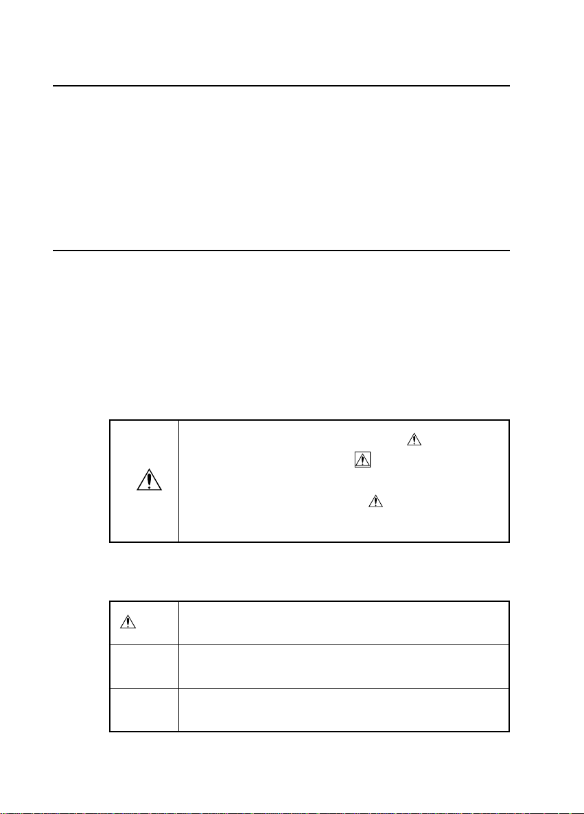
安全記号
この取扱説明書には、本器を安全に操作し、安全な状態を保つのに要する
情報や注意事項が記載されています。本器を使用する前に、下記の安全に
関する事項をよくお読みください。
・操作者は、機器上の表示されている マークのとこ
ろについて、取扱説明書の
し、機器の操作をしてください。
・操作者は、取扱説明書の中の
ず説明を読む必要があることを示します。
マーク該当箇所を参照
マークのところは必
○本説明書の注意事項には重要度に応じて以下の表記がされています。
危険
注意
注記
──────────────────────────────────────
操作や取扱を誤ると、使用者が死亡または重傷につなが
る危険性が極めて高いことを意味します。
操作や取扱を誤ると、使用者が傷害を負う場合、または
機器を損傷する可能性があることを意味します。
製品性能および操作上でのアドバイス的なことを意味し
ます。
Page 5

──────────────────────────────────────
点 検
本器が届きましたら、輸送中において異常または破損がないかを点検して
ください。万一、破損あるいは仕様どおり動作しない場合は、最寄りの代
理店か営業所にご連絡ください。
3
──────────────────────────────────────
Page 6

4
──────────────────────────────────────
ご使用にあたっての注意
本器を安全にご使用いただくために、また機能を十二分にご活用いただく
ために、下記の注意事項をお守りくださるようお願いいたします。
・運搬および取扱の際は振動、衝撃を避けてください。特に、落
下などによる衝撃に注意してください。
・直射日光や高温、多湿、結露させるような環境下での保存、使
用は避けてください。変形、絶縁劣化を起こし、仕様を満足し
なくなります。
・使用前には、過酷な保存や輸送などによる故障がないかを、点
検と動作確認をしてから使用してください。故障を確認した場
合は、最寄りの代理店か営業所にご連絡ください。
・コア部つき合わせ面にゴミなどが付着した場合は、測定に影響
がでますので柔らかい布にて軽く拭き取ってください。
注意
・コア部に機械的な衝撃を加えないようにしてください。コア面
に傷がついた場合は正確な測定ができません。
・センサケーブル(特にセンサ側の付け根)は、断線による故障
を防ぐため折ったり引っ張たりせず取扱には注意してくださ
い。
・カレントモニタおよびセンサの損傷を防ぐため、電源が入った
状態ではセンサコネクタの抜き差しを行わないでください。
・カレントモニタの電源を投入した状態では、被測定導体を挟み
込むとき以外はセンサの先端を閉じておいてください。(開い
たままにすると損傷してしまう恐れがあります)
・センサを分解すると開閉機構などを損傷し、使用できなくなり
ます。
──────────────────────────────────────
Page 7

──────────────────────────────────────
1. 概 要
1.1 製品概要
本器は、3270カレントモニタに接続することにより、被測定導体を切
断することなく被測定導体を挟み込むだけで電流波形を出力することがで
きます。
記録計、オシロスコープなどで簡単に電流波形を記録、観測することがで
きます。
1.2 特 長
・高確度な電流検出
・簡易な電流測定
・センサの完全な互換性
・広帯域な周波数特性
DC〜1MHz(−3dB)
・大窓径で大電流測定可能
・過大入力時の保護機能
・独自開発の薄膜ホール素子採用
5
──────────────────────────────────────
1.2 特 長
Page 8

6
ク
面
ーコア部
タ
ル
──────────────────────────────────────
2. 各部の名称
電流方向マー
レバ
つき合わせ
センサケーブ
センサコネク
──────────────────────────────────────
Page 9

──────────────────────────────────────
3. 操作方法
3270カレントモニタの取扱説明書の『測定方法』を合わせて参照して
ください。
3.1 使用上の注意
・クランプ製品は、短絡、人身事故などを避けるために、600Vピ
危険
ーク以下の電路で使用してください。
・クランプコアの先端を開いたときの短絡、人身事故などを避け
るために、裸導体には使用しないでください。コアおよびシー
ルドケースが絶縁されていません。
7
3.2 操作方法
(1) レバーを軽く押し、センサ部先端を開いてください。
(2) センサ部に表示してある電流方向マークの矢印が負荷側を向くようにし
て、被測定導体が中央になるようにクランプしてください。
注記 中央にしないと導体位置の影響を受ける場合があります
(3) センサを握って、レバーが確実にロックされたことを確認してください。
注記 ロックされていない状態では、正確な測定ができません
──────────────────────────────────────
3.2 操作方法
Page 10

8
──────────────────────────────────────
・最大入力範囲を超える電流を入力しないでください。最大入力
範囲は測定電流の周波数によって異なります。(図2参照)
・最大入力範囲を超える電流を入力した場合は、センサ部の発熱
により内部回路の保護機能が働くため正常な出力をしなくなり
注意
注記
・電源投入直後は、カレントモニタおよび本器の自己発熱の影響などにより
オフセットドリフトが大きい場合があります。
・オフセット電圧は、周囲温度などによりドリフトしますので、連続測定を
行う際には注意が必要です。
・測定電流値の大きさおよび周波数によっては、共振により音が発生する場
合がありますが、測定には影響ありません。
・近接して大電流電路がある場合などは、外部磁界の影響を受ける場合があ
ります。
ます。ただちに入力が無い状態(被測定導体からセンサを外す
か入力電流をゼロにする)にしてください。(再び正常な動作
をするまでには十分な冷却時間が必要となります)
・上記のことを繰り返し行ったり、最大入力範囲を超える電流を
入力し続けたりすると本器を損傷する恐れがあります。
──────────────────────────────────────
3.2 操作方法
Page 11

──────────────────────────────────────
4. 製品仕様
確度は23℃± 3℃、電源投入後30分にて
定 格 電 流:150A(AC+DC成分)
出 力 電 圧:1.5V/150A(AC+DC成分)
出 力 抵 抗:50Ω
入力インピーダンス:55Hzにて0.02mΩ以下 (図1参照)
連続最大入力範囲:150A (図2参照)
最大ピーク電流値:非連続で400A(ピーク値)
振 幅 確 度:±0.5%rdg.±0.1%f.s. (DC, 45〜66Hz)
位 相 確 度:±0.2 ゜(45〜66Hz)
周 波 数 帯 域: DC 〜 1MHz(−3dB) (特性例は図3参照)
周 波 数 特 性: DC 〜 10kHz : ±2.0%以内
(確度からの偏差) 10kHz 〜 100kHz : ±4.0%以内
感度の温度係数:±0.05%f.s./ ℃以内(0〜40℃の範囲において)
ノ イ ズ:1mVrms 以下(〜20MHz電圧計)
消 費 電 力:2VAmax.(定格入力時)
電 源 電 圧:±12V±1V
使 用 温 湿 度:0〜40℃,80%RH以下(結露しないこと)
保 存 温 湿 度:−10〜50℃,80%RH以下(結露しないこと)
外部磁界の影響:最大1A相当(400A/mの交流磁界にて)
導体位置の影響:±1%以内
耐 電 圧:AC2200V 1分間(電気回路−ケース間)
絶 縁 抵 抗:DC500V 100MΩ以上(電気回路−ケース間)
最高使用回路電圧:600Vピーク(コアおよびシールドケースと電気
(絶縁導体) 回路は絶縁されていません)
測定可能導体径:φ20mm
コ ー ド 長:約1.5m
外形寸法、質量:約145(W)×60(H)×33(D)mm、約300g
付 属 品:取扱説明書、携帯用ケース
9
──────────────────────────────────────
Page 12

10
──────────────────────────────────────
図1.入力インピーダンス
図2.最大入力範囲
図3.周波数帯域 (特性例)
──────────────────────────────────────
Page 13

Page 14

Page 15

Contents
Introduction 1
Notes on Safety 1
Inspection 2
Notes on Use 3
Chapter 1 General 5
1.1 Product Overview 5
1.2 Features 5
Chapter 2 Identification of Indicators 7
Chapter 3 Measurement Procedure 9
3.1 Notes on Use 9
3.2 Measurement Procedure 9
Chapter 4 Product Specifications 11
Page 16

――――――――――――――――――――――――――――――――――――――
G
I
N
ntroduction
Thank you for purchasing this Hioki 9276 Clamp-On
AC/DC Sensor. In order to use this product effectively
and to ensure that it enjoys a long operational life, read
this Instruction Manual carefully and then retain it for
future reference.
otes on Safety
1
WARNIN
This instrument is designed to prevent accidental
shock to the operator when properly used. However
no engineering design can render safe an instrument
which is used carelessly. Therefore, this manual
must be read carefully and completely before making
any measurement. Failure to follow directions can
result in a serious of fatal accident.
Safety Symbols
This Instruction Manual provides information and
warnings essential for operating this equipment in a safe
manner and for maintaining it in safe operating
condition. Before using this equipment, be sure to
carefully read the following safety notes.
This symbol is affixed to locations on the equipment
where the operator should consult corresponding
topics in this manual (which are also marked with the
symbol) before using relevant functions of the
equipment.
In the manual, this mark indicates explanations
which it is particularly important that the user read
before using the equipment.
――――――――――――――――――――――――――――――――――
Page 17

2
R
G
N
I
――――――――――――――――――――――――――――――――――――――
The following symbols are used in this Instruction
Manual to indicate the relative importance of cautions
and warnings.
Indicates that incorrect operation presents extreme
DANGE
danger of accident resulting in death or serious
injury to the user.
Indicates that incorrect operation presents
WARNIN
significant danger of accident resulting in death or
serious injury to the user.
Indicates that incorrect operation presents
CAUTIO
possibility of injury to the user or damage to the
equipment.
NOTE
nspection
When the unit is delivered, check and make sure that it
has not been damaged in transit. In particular, check the
accessories, core section, and sensor connector.
If the unit is damaged, or fails to operate according to the
specifications, contact your dealer or Hioki representative.
Denotes items of advice related to performance of
the equipment or to its correct operation.
――――――――――――――――――――――――――――――――――
Page 18

――――――――――――――――――――――――――――――――――――――
N
N
otes on Use
In order to ensure safe operation and to obtain maximum
performance from the unit, observe the cautions listed
below.
3
CAUTIO
・ Do not subject the unit to vibrations or shocks during
transport or handling. Be especially careful to avoid
dropping the unit.
・ Do not store the unit where it will be exposed to direct
sunlight, high temperature, high humidity, or
condensation. If exposed to such conditions, the unit
may be damaged, the insulation may deteriorate, and
the unit may no longer satisfy its specifications.
・ Before using the unit, inspect it and check the operation
to make sure that the unit was not damaged due to
poor storage or transport conditions.
If damage is found, contact your dealer or Hioki
representative.
・ If there is any type of dust or dirt on the core contact
surfaces, measurements may be affected. Wipe it
away gently with a soft cloth.
・ Do not apply any sort of mechanical impact to the core
section. Scratches on the core surfaces will make
accurate measurements impossible.
・ Do not bend or pull the sensor cable (especially where
the cable connects to the sensor) in order to avoid
damaging the sensor cable.
・ In order to prevent damages of the Current Monitor and
this unit, never plug in or unplug the sensor connector
when the power is turned on.
――――――――――――――――――――――――――――――――――
Page 19

4
N
――――――――――――――――――――――――――――――――――――――
CAUTIO
・ When the power for the Current Monitor is on, keep the
core section closed, except when clamping them onto
the conductor to be measured. (The facing surface of
the core section can be scratched while it is open.)
・ Taking the unit apart may damage the open-close
mechanism that could result in an inoperative unit.
――――――――――――――――――――――――――――――――――
Page 20

――――――――――――――――――――――――――――――――――――――
1
al
1
1
Chapter
Gener
.1 Product Overview
When connected to the 3270 Current Monitor, this clampon sensor can output current waveforms without any need
to cut the conductor being measured, simply by clamping
the sensor onto the conductor.
This equipment can thus be used in conjunction with a
recorder, an oscilloscope, or other such equipment in order
to record and measure current waveforms.
5
.2 Features
Highly accurate cu rrent detection
Easy current me asurement
Complete sensor compatibility
Broadband frequency characteristics DC to 1 MHz
(-3dB)
Large opening and permits measurement of high
current levels.
Protectfunctionatexcessiveinput
Particular developed thi n film Hall element adoption.
――――――――――――――――――――――――――――――――――
Chapter 1 General
Page 21

6
――――――――――――――――――――――――――――――――――――――
――――――――――――――――――――――――――――――――――
Chapter 1 General
Page 22

――――――――――――――――――――――――――――――――――――――
e
n
r
e
k
2
rs
Chapter
Identification of Indicato
Current direction mar
Lever
Facing surfac
7
Core sectio
Sensor connecto
Sensor cabl
――――――――――――――――――――――――――――――――――
Chapter 2 Identification of Indicators
Page 23

8
――――――――――――――――――――――――――――――――――――――
――――――――――――――――――――――――――――――――――
Chapter 2 Identification of Indicators
Page 24

――――――――――――――――――――――――――――――――――――――
R
3
re
3
3
Chapter
Measurement Procedu
For details on how to take measurements, refer to Section
1.4, "Measurement Procedure" of the 3270 Current
Monitor Instruction manual.
.1 Notes on Use
9
DANGE
In order to prevent short circuits and injury or
death, only use this sensor on circuits carrying less
than 600 V peak.
In order to prevent short circuits and electric
shocks while the core section is open, do not use
this sensor on bare conductors. The core and
shield case are not insulated.
.2 Measurement Procedure
(1) Gently press the lever of the sensor to open the core
section.
(2) Position the sensor so that the current direction mark on
the sensor part points in the direction of the load and so
that the conductor being measured is centered, and then
close the core section.
――――――――――――――――――――――――――――――――――
Chapter 3 Measurement Procedure
Page 25

10
N
――――――――――――――――――――――――――――――――――――――
NOTE
NOTE
CAUTIO
If the conductor being measured is not centered, the
results may be affected by its position.
(3) Confirm that the lever is completely locked.
Accurate measurement is not possible if the sensor is not
locked.
・ Do not exceed the maximum allowable current input.
The maximum input range differs, depending on the
frequency of measured current. (See Figure 2.)
・ If current exceeds the maximum allowable input,
overheating of the sensor will trip the protective function
for the internal circuitry, so the unit will no longer
produce accurate output. If this happens, eliminate the
input immediately (either by removing the sensor from
the conductor being measured or by reducing the input
current to zero). (Wait until the sensor has had
sufficient time to cool before resuming operation.)
・ If the above situation occurs repeatedly, or if current in
excess of the maximum input range is input
continuously, the sensor could be damaged.
NOTE
・ Immediately after powering on, there may in some cases
be a large offset drift caused by self-generated heat from
the Current Monitor and this unit.
・ When performing continuous measurements, it is
necessary to be aware that the offset voltage drifts,
depending on factors such as the ambient temperature.
・ Depending on the measured current value and the
frequency, however some sound may be produced by
resonation, it has no effect on measurements.
・ If a circuit carrying a large current is nearby,
measurements may be affected by external magnetic
fields.
――――――――――――――――――――――――――――――――――
Chapter 3 Measurement Procedure
Page 26

――――――――――――――――――――――――――――――――――――――
4
s
11
Chapter
Product Specification
(Accuracy is guaranteed at 23℃±3℃ after the power has
been on for 30 minutes)
■ Rated current 150 A (AC + DC)
■ Output voltage 1.5 V /150 A (AC + DC)
■ Output resistance 50 Ω
■ Input impedance 0.02 mΩ or less at 55 Hz
(see Figure 1)
■ Continuous maximum 150 A (see Figure 2)
input range
■ Maximum peak 400 A noncontinuous
current value (peak value)
■ Amplitude accuracy ±0.5 % rdg. ±0.1 % f.s.
(DC, 45 to 66 Hz)
■ Phase accuracy ±0.2
■ Frequency band DC to 1 MHz (-3 dB) (see Figure
3, example of characteristics)
■ Frequency characteristics DC to 10 kHz: ±2.0 % or less
(Deviation from accuracy) 10 kHz to 100 kHz: ±4.0 % or
less
■ Temperature for ±0.05 % f.s./℃ or less
sensitivity (within a range of 0 to 40℃)
■ Noise 1 mV rms or less (with a
voltmeter for up to 20 MHz)
■ Power consumption 2 VA max. (with rated input)
■ Supply voltage ±12 V ±1V
■ Operating temperature 0to40℃, 80 % RH or less
and humidity (no condensation)
(45 to 66 Hz)
――――――――――――――――――――――――――――――――――
Chapter 4 Product Specifications
Page 27

12
――――――――――――――――――――――――――――――――――――――
■ Storage temperature -10 to 50℃, 80 % RH or less
and humidity (no condensation)
■ Effect of external Equivalent to a maximum of 1 A
magnetic fields (in a 400 A/m AC current
magnetic field)
■ Effect of conductor Within ±1%
position
■ Dielectric strength 2200 V AC for 1 minute
(between electric circuit and case)
■ Insulation resistance 500 V DC, 100 MΩ or more
(between electric circuit and case)
■ Maximum permitted 600 V peak; (the core, shield
circuit voltage case, and electrical circuits are
(insulated conductor) not insulated.)
■ Diameter of measurable 20 mm dia.
conductors
■ Cord length Approx. 1.5 m
■ External dimensions Approx. 145 (W) × 60 (H) × 33
and mass (D) mm, approx. 300 g
■ Accessories Instruction manual, carrying
case
――――――――――――――――――――――――――――――――――
Chapter 4 Product Specifications
Page 28

――――――――――――――――――――――――――――――――――――――
Frequency (Hz)
)
Figure 1 Input Impedance
)
)
Figure 2 Maximum Input Range
)
)
Figure 3 Frequency Characteristics
Input impedance (mΩ
13
Maximum input current (A rms
Frequency (Hz
Phase
Amplitude
Amplitude (dB, 0dB=1V)
Frequency (Hz
Phase (deg.
――――――――――――――――――――――――――――――――――
Chapter 4 Product Specifications
Page 29

14
――――――――――――――――――――――――――――――――――――――
――――――――――――――――――――――――――――――――――
Chapter 4 Product Specifications
Page 30

 Loading...