

Page 1
接続可能機種については、弊社カタログをご覧ください。
9269, 9269-10
DC バイアス電流ユニット
DC BIAS CURRENT UNIT
取扱説明書 / Instruction Manual
Aug. 2018 Revised edition 7 Printed in Japan
9269A980-07 18-08H
JA/EN
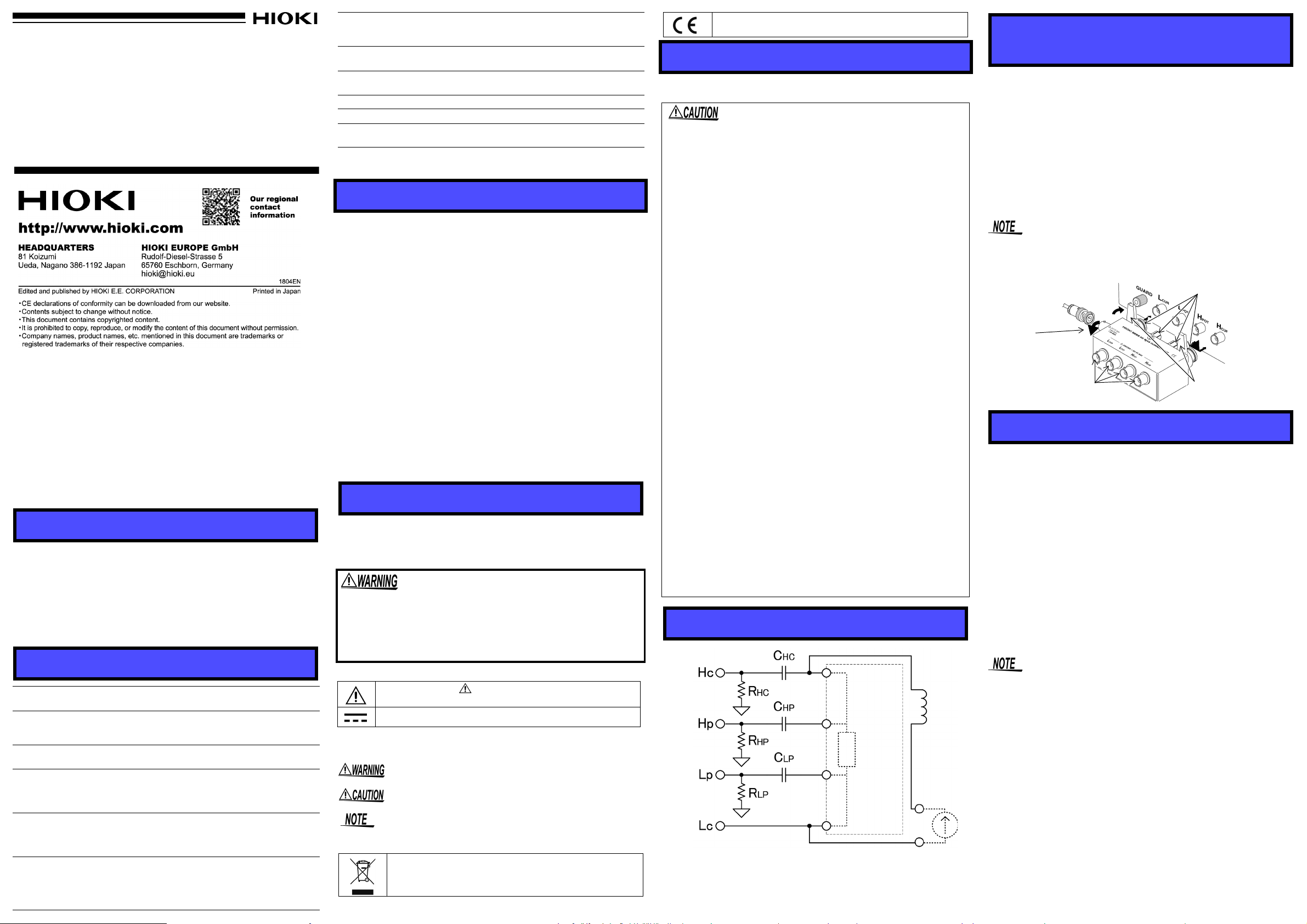
外部 DC バイアス電源と内部インダクタンスの直列回路が測定端子
の H-L 端子間(測定試料間)に並列に接続されるため、試料のイン
ピーダンス値が十分小さくない場合には測定誤差が生じます。
内部インダクタンス
測定試料
(フィクスチャ別売り)
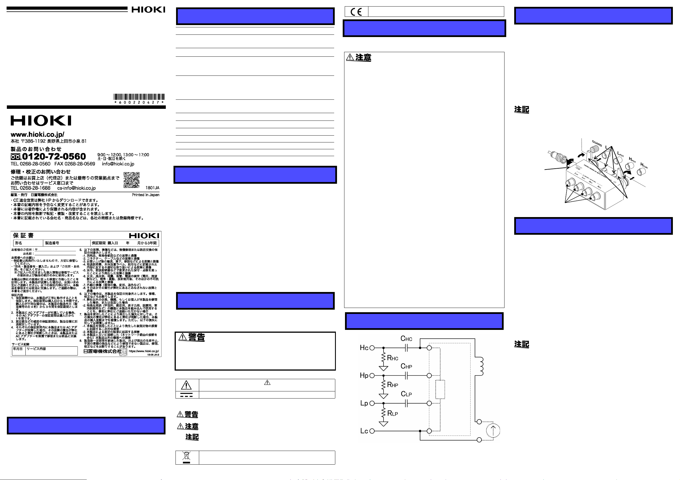
接続端子
外部 DC バイアス印加端子
*9269 は R
HC
, RHPなし
外部 DC
バイアス
印加端子
測定端子
(フィクスチャを接続)
レバー
接続端子(本体に接続)
仕様
EU 指令が示す規制に適合していることを示します。
接続方法
測定周波数範囲 42 Hz ~ 100 kHz (9269-10 は 40 Hz ~ 2 MHz)
最大印加電圧 H 端子‐ L 端子間、外部 DC バイアス印加端子間:
DC ± 40 V
最大印加電流
最大対地間電圧 H端子‐筐体間、外部DCバイアス印加端子-筐体間:
残留パラメータ
(参考値)
外形寸法 ・ 質量 約 116W x 45H x 55D mm (突起物含まず)
使用温湿度範囲 0 ~ 40°C, 80%rh 以下 ( 結露なきこと )
保存温湿度範囲 -10°C ~ 55°C, 80%rh 以下 ( 結露なきこと )
使用場所 屋内 , 汚染度 2, 高度 2000 m まで
適合規格
付属品 取扱説明書
製品保証期間 3年間
接続可能機種については、弊社カタログをご覧ください。
外部 DC バイアス印加端子間:DC
DC ± 40 V
L 端子 - 筐体間:DC ± 0.5 V
残留インピーダンス: 50 mΩ + 2 x π x 周波数 x 50
nH
内部インダクタンス:3 mH(1 kHz)
9269-10 は 300 uH(1 kHz)
9269:約 300 g, 9269-10:約 280 g
EN61010
±2 A
点検・保守
点検
本器がお手元に届きましたら、輸送中において異常または破損がない
か点検してからご使用ください。万一、破損あるいは仕様どおり動作
しない場合は、お買上店(代理店)か最寄りの営業所にご連絡ください。
使用前の確認
• 使用前には、保存や輸送による故障がないか、点検と動作確認をし
てから使用してください。故障を確認した場合は、お買上店 ( 代理
店 ) か最寄りの営業所にご連絡ください。
保守・サ-ビス
• 本器の汚れをとるときは、柔らかい布に水か中性洗剤を少量含ませ
て、軽く拭いてください。ベンジン、アルコ-ル、アセトン、エ-
テル、ケトン、シンナ-、ガソリン系を含む洗剤は絶対に使用しな
いでください。変形変色することがあります。
• 故障と思われるときは、
絡ください。輸送中に破損しないように梱包し、故障内容も書き添
えてください。輸送中の破損については保証しかねます。
お買上店(代理店)
か最寄りの営業所にご連
安全について
この取扱説明書には本器を安全に操作し、安全な状態に保つのに要す
る情報や注意事項が記載されています。本器を使用する前に、次の安
全に関する事項をよくお読みください。
使用上の注意
本器を安全にご使用いただくために、また機能を十分にご活用いただ
くために、次の注意事項をお守りください。
• 直射日光や高温、多湿、結露するような環境下での、保存や使用は
しないでください。変形、絶縁劣化を起こし、仕様を満足しなくな
ります。
• 腐食性ガスや爆発性ガスが発生する場所では使用しないでくださ
い。本器を破損する可能性があります。
• 本器は防じん、防水構造となっていません。ホコリの多い環境や水
のかかる環境下で使用しないでください。故障の原因になります。
• 本器の損傷を防ぐため、運搬および取り扱いの際は振動、衝撃を避
けてください。特に、落下などによる衝撃に注意してください。本
器を破損します。
• 水にぬれたり、油、ホコリでひどくなった時は、使用を中止し弊社
の修理サービスをお受けください。
• 接続機種、フィクスチャの取扱方法は、その機種の取扱説明書をご
覧ください。
• DC バイアスユニットを測定器本体に接続したまま、上から重み
をかけないでください。測定器本体、本器の破損の原因になります。
• 9269, 9269-10 に印加できる DC バイアス電流は、最大 DC2 A で
す。これ以上の DC バイアス電流を常時印加すると測定器本体、本
器を破損する恐れがあります。
• 試料の定格電流以上のDC バイアス電流を試料に印加しないでくだ
さい。試料、本器、測定器本体の破損の原因になります。
• 感電事故を避けるため、DC バイアス電流を印加したまま、測定端
子間には絶対に触らないでください。
•DCバイアス電流を印加したまま、フィクスチャを短絡しないでく
ださい。フィクスチャを破損し、短絡事故になります。
• 試料、外部 DC バイアス電源の接続時は、各極性に十分ご注意くだ
さい。
• 測定後は外部DCバイアス電源の出力を0 Aにしてから試料をプロー
ブからはずしてください。測定器本体の破損の原因になります。
• 3522, 3522-50 に接続して使用する場合は、3522, 3522-50 の
EXT.DC BIAS 設定を OFF にしてください。EXT.DC BIAS 設定が
ON の場合は測定器本体の破損の原因になります。
•IMシリーズに接続して使用する場合は IM シリーズの DC バイアス
設定で SET EXT ボタンを押してください。
• 本器を接続機種から着脱するときは、接続機種の測定端子に対して
まっすぐに挿抜して下さい。斜めに挿抜した場合は接続端子が変形
し、測定値に影響を与える可能性があります。
内部回路
DC バイアス電流ユニットの接続方法
形名が印刷されている面を上にして、測定器本体の測定端子
(UNKNOWN端子)に直接差し込み、左右のレバーで固定してください。
テストフィクスチャの接続方法
9269, 9269-10 の測定端子(UNKNOWN 端子)に H 側、L 側が合うよ
うにフィクスチャ(または測定プローブ)を接続してください。試料
の固定方法はフィクスチャの取扱説明書を参照してください。
外部 DC バイアス電源の接続方法
外部 DC バイアス電源の出力が OFF になっていることを確認し、9269,
9269-10 の外部 DC バイアス印加端子(BNC 端子)にケーブルを差し
込み、接続してください。
• 外部 DC バイアス電源は別途必要です。
•LCRハイテスタ本体から DC バイアス電源をコントロールすること
はできません。
測定方法
安全に測定を行うために必ず次の手順に従って測定を行ってくださ
い。また、測定前には使用上の注意を必ずお読みください。
1.DC バイアスユニットの内部回路による測定誤差をなくすため、測
定前に、オープン補正、ショート補正を必ず行ってください。オー
プン補正、ショート補正は 9269(または 9269-10)、フィクスチャ
(または測定プローブ)を接続し、バイアス印加ケーブルを繋がない
状態で行ってください。補正方法は測定器本体、フィクスチャの取
扱説明書を参照してください。
2.試料をフィクスチャに固定します。
3. 外部 DC バイアス電源の出力電流を 0 A に設定してから、電流を印加
します。出力電流を少しずつ上げていき、測定したい電流にします。
4.試料の DC バイアス特性の測定を行います。
5. 外部DC バイアス電源の出力電流を少しずつ下げていき、0 A にします。
6.試料をフィクスチャから取り外します。
はじめに
このたびは、HIOKI 9269, 9269-10 DC バイアス電流ユニットをご選定
いただき、誠にありがとうございます。この製品を十分にご活用いた
だき、末長くご使用いただくためにも、取扱説明書はていねいに扱い、
いつもお手元に置いてご使用ください。
※ 9269 と 9269-10 は内部回路が異なります。必ず接続先の測定器で
指定されたものをお使いください。
概要
9269 DC バイアス電流ユニットは弊社 LCR, Z ハイテスタ、9269-10
は弊社 IM シリーズ(LCR メータ、インピーダンスアナライザ)とフィ
クスチャの間に接続し、インダクタ、トランス等に外部 DC バイアス
電流を印加するためのオプションユニットです。
この機器は測定方法を間違えると人身事故や機器の故障につ
ながる可能性があります。取扱説明書を熟読し、十分に内容
を理解してから操作してください。万一事故があっても、弊
社製品が原因である場合以外は責任を負いかねます。
安全記号
使用者は、取扱説明書内の マ-クのあるところは、必
ず読み注意する必要があることを示します。
直流(DC)を示します。
取扱説明書の注意事項には、重要度に応じて次の表記がされています。
操作や取り扱いを誤ると、使用者が死亡または重傷につな
がる可能性があることを意味します。
操作や取り扱いを誤ると、使用者が傷害を負う場合、また
は機器を損傷する可能性があることを意味します。
製品性能および操作上でのアドバイスを意味します。
規格に関する記号
EU 加盟国における、電子電気機器の廃棄にかかわる法規
制 (WEEE 指令 ) のマークです。
• IM3570 は DC バイアスユニットを接続した状態でショート補正をす
ることができませんので、仕様の残留インピーダンスが、誤差とし
て加算されます。
•DCバイアスユニットをIMシリーズと接続してオープン補正、ショー
ト補正を行う場合は、IM シリーズの補正範囲の設定で DC を OFF
にして下さい。
•DCバイアスユニットは 4 端子対構造ではありません。4 端子対構造
のテストフィクスチャ・プローブと組み合わせて使用する場合は、
測定誤差が増えたりプローブの配置の影響を受けやすくなります。
• IM3570 と DC バイアスユニットを接続して使用し、低 Z 高精度モー
ドの ON/OFF を切り替える場合、5 秒程度の安定時間が必要です。
• 接続する外部 DC バイアス電源によっては、測定誤差が大きくなる
場合があります。
• 試料に印加した DC バイアス電流が設定値になるまでには、ある程
度時間がかかります。この間は測定値が安定しませんので、ご注意
ください。
Page 2
Warranty
9269, 9269-10
DC BIAS CURRENT UNIT
Instruction Manual
Aug. 2018 Revised edition 7 Printed in Japan
9269A980-07 18-08H
EN
Since the series circuit of the external DC bias power supply and the interna
inductance is connected in parallel between the terminals H and L of the mea
surement terminals (between measurement samples), measurement error
occurs when the impedance value of the sample is not sufficiently small.
Internal inductance
DUT (Fixture is option)
Connecting terminals
External DC bias applying terminal
*Model 9269 does not have
R
HC
or RHP.
External
DC bias apply
terminal
Connecting terminals
Fixing lever
(Attached to the
instrument)
Measurement terminals
(Attach fixture here)
Warranty malfunctions occurring under conditions of normal use in conformity with the Instruction Manual and Product Precautionary Markings
will be repaired free of charge. This warranty is valid for a period of
three (3) years from the date of purchase. Please contact the distributor
from which you purchased the product for further information on warranty provisions.
Introduction
Thank you for purchasing the HIOKI Model 9269, 9269-10 DC BIAS
CURRENT UNIT. To obtain maximum performance from the
please read this manual first, and keep it handy for future refer-
uct,
ence.
Overview
The HIOKI 9269 DC BIAS CURRENT UNIT is an optional unit,
which can be connected between a HIOKI LCR, Z HiTESTER and
the fixture,The 9269-10 DC BIAS CURRENT UNIT is an optional
unit, which can be connected between a HIOKI IM Series (LCR
Meters, Impedance Analyzers) and the fixture, to allow a DC bias
current to be applied to an inductor or transductor.
The internal circuits of 9269 and 9269-10 are all different. Please
use the correct circuit specified by the tester to be connected.
Specifications
Measurement
frequency range
Maximum apply
voltage
Maximum apply
current
Maximum voltage to
earth
Residual parameters
(reference value)
Dimensions and
Mass
42 Hz to 100 kHz (9269-10: 40 Hz to 2 MHz)
Between the terminals of H-L and external DC
bias apply terminal :
±40 VDC
Between the external DC bias apply terminal :
±2 ADC
Between the H terminal and chassis, external
DC bias terminal and chassis :
±40 VDC
Between the L terminal and chassis : ±0.5 VDC
Residual impedance : 50 mΩ + 2 x π x Fre-
Internal inductance : 3 mH (1 kHz)
Approx.116W x 45H x 55D mm
(4.57”W x 1.77”H x 2.17”D)
(excluding protrusions)
9269: Approx. 300 g (10.6 oz.)
9269-10: Approx. 280 g (9.9 oz.)
quency x 50 nH
(9269-10: 300 uH (1 kHz))
prod-
Operating temperature and humidity
range
Storage temperature
and humidity range
Operating
environment
Applicable Standards EN61010
Accessory Instruction Manual
Product warranty
period
0 to 40°C (32 to 104
(with no condensation)
-10°C to 55°C (14 to 131
(with no condensation)
Indoors, Pollution Degree 2
altitude up to 2000 m (6562-ft.)
3 years
°F)
, 80%RH or less
°F)
, 80%RH or less
Please check a HIOKI catalog for instruments to which this product can be connected.
Inspection and Maintenance
Initial Inspection
When you receive the product, inspect it carefully to ensure that
no damage occurred during shipping. If damage is evident, or if
it fails to operate according to the specifications, contact your
dealer or HIOKI representative.
Preliminary Checks
• Before using the product the first time, verify that it operates
normally to ensure that the no damage occurred during storage or shipping. If you find any damage, contact your dealer
or Hioki representative.
Maintenance and Service
• To clean the product, wipe it gently with a soft cloth moistened
with water or mild detergent. Never use solvents such as benzene, alcohol, acetone, ether, ketones, thinners or gasoline,
as they can deform and discolor the case.
• If the product seems to be malfunctioning, contact your dealer
or Hioki representative. Pack the product carefully so that it
will not be damaged during shipment, and include a detailed
written description of the problem. Hioki cannot be responsible for damage that occurs during shipment.
Safety
This manual contains information and warnings essential for
safe operation of the product and for maintaining it in safe operating condition. Before using it, be sure to carefully read the following safety precautions.
Mishandling during use could result in injury or death, as
well as damage to the product. Be certain that you understand the instructions and precautions in the manual
before use. We disclaim any responsibility for accidents or
injuries not resulting directly from product defects.
Safety Symbol
In the manual, the symbol indicates particularly important
information that the user should read before using the product.
Indicates DC (Direct Current).
The following symbols in this manual indicate the relative importance of cautions and warnings.
Indicates that incorrect operation presents a significant hazard that could result in serious injury or death to the user.
Indicates that incorrect operation presents a possibility of
injury to the user or damage to the product.
Advisory items related to performance or correct operation
of the product.
Symbols for Various Standards
Indicates the Waste Electrical and Electronic Equipment
Directive (WEEE Directive) in EU member states.
Indicates that the product conforms to regulations set out
by the EU Directive.
Operating Precautions
Follow these precautions to ensure safe operation and to obtain
the full benefits of the various functions.
• Do not store or use the product where it could be exposed to direct
sunlight, high temperature or humidity, or condensation. Under
such conditions, the product may be damaged and insulation may
deteriorate so that it no longer meets specifications.
• Do not use the product where it may be exposed to corrosive or
combustible gases. The product may be damaged.
• This product is not designed to be entirely water- or dust-proof. To
avoid damage, do not use it in a wet or dusty environment.
• To avoid damage to the product, protect it from vibration or shock during
transport and handling, and be especially careful to avoid dropping.
• If the fixture has gotten seriously wet, oily, or dusty, stop using it
and send it for service at an approved HIOKI service facility.
• For using the tester to which the test fixture is connected and fixture, refer to Instruction Manual of them.
• When the DC bias unit is attached to the tester, be careful not to
put any weight on it. This could lead to damage both to the tester
and to the DC bias unit.
• The maximum DC bias current which can be supplied to the 9269,
9269-10 is 2 ADC. If a DC bias current greater than this limit is supplied continuously, the units may be damaged.
• Do not apply the DC bias current more than rated current of sample. Doing so may damage the sample and testers.
• In order to avoid electric shock accident, be absolutely sure not to touch
the test terminals while the DC bias current is being supplied to them.
• Do not short circuit of the fixture with the DC bias current still being supplied. Doing so may damage the fixtures or cause a short circuit accident.
• Be careful about the polarity when connecting together, the sample
to be tested, and the external DC bias power supply.
• After testing is completed, drop the output current of the external DC bias
power supply to zero ampere, and remove the sample under test from
the probes. If not done properly, it could lead to damage to the tester.
• When using with Model 3522 or 3522-50 turn OFF the EXT.DC
BIAS setting.Switching the EXT.DC BIAS setting ON can cause the
LCR meter to malfunction.
• When using with IM Series, press the SET EXT button in the DC
bias setting of the IM Series.
• When connecting or disconnecting this product from the connected
device, plugging it straight to the measurement terminal of the connected device. If the connection is incorrect, connecting terminal is
deformed and may affect the measurement.
Internal circuitry
Connecting the DC Bias Current Unit and Test Fixture
DC bias current unit.
Plug the fixture into the measurement terminals (UNKNOWN) of the
tester, with the product name up. Fasten it in place with the left and right
fixing levers.
Test fixture
Connect the test fixture (or measurement probe) to the measurement terminals (UNKNOWN) of the tester, so that the H and L terminals match.
For fixing sample, refer to the Instruction Manual of the fixture.
External DC bias power supply
Make sure that the external DC bias power supply is turned off, and
then plug the cable into the external DC bias apply terminals (BNC terminal) of the 9269, 9269-10 to connect.
• A separate external power supply for the DC bias current is also
required.
• The DC bias power supply cannot be controlled by the main unit of
the LCR HiTester.
Measurement Method
For safety reason, follows the procedure carefully.
Before measurement, always read the operating precautions.
1.To eliminate measurement errors due to the internal circuit of the DC
bias unit, before carrying out measurement, always carry out opencircuit compensation and short-circuit compensation. Carry out the
open-circuit compensation and short-circuit compensation with the
9269 (or 9269-10) and fixture (or measurement probe) connected,
and with the bias application cable not connected. For details on
compensation, refer to Instruction Manuals of the tester and fixture.
2.Fix the sample in the fixture.
3.Set the output current of the external DC bias supply to 0 A, then
apply the current. Next, increase the output current setting
progressively to reach the required setting.
4.Measure the DC bias characteristics of the sample.
5.Gradually decrease the output current of the external DC bias
supply until it reaches 0 A.
6.Remove the sample from the fixture.
• Since the IM3570 is not be able to compensate the short-circuit
while it is connected to the DC bias unit, residual impedance of the
specification will be added as an error.
• When carrying out open-circuit compensation or short-circuit
compensation using DC bias unit connected to IM Series, turn OFF
the DC setting of the correction range of IM Series.
• DC bias unit is not a four-terminal pair structure. When it is in
combination with the test fixture probes that is four-terminal pair
structure, measurement error increases or the measurement results
may be affected by the placement of the probe.
• When the DC bias unit is used connected to IM3570, and switching
between the ON and OFF of low-Z high precision mode, stabilization
time of about 5 seconds is required.
• Depending on the connected external DC bias power supply, it may
increase the chance of measurement inaccuracy.
• It takes a little time for the DC current which is being supplied to the
sample under test to reach the set current, so you should wait for a
certain stabilization time period before performing testing. Be careful,
because if you perform testing before this stabilization time period
has elapsed, the results will not be reliable.
 Loading...