

Page 1
8953-10
)
,
高分解能ユニット/
HIGH RESOLUTION UNIT
取扱説明書/
2006年9
1. はじめに
・このたびは、HIOKI 8953-10 高分解能ユニット をご選定いただき、
誠にありがとうございます。この製品を十分にご活用いただき、末長
くご使用いただくためにも、取扱説明書はていねいに扱い、いつもお手
元に置いてご使用ください。
・8953-10 高分解能ユニットは、メモリハイコーダのオプション品です。
必ずメモリハイコーダ に装着してご使用ください。取付方法、使用方法
など詳細については、メモリハイコーダ本体の取扱説明書を参照して
ください。
・
「3.安全のために守るべきこと」
安全について
2.
月 改訂2版
8953B980-02 06-09H
Instruction Manual
Printed in Japan
をよくお読みのうえ、ご使用ください。
安全のために守るべきこと
3.
8953-10
分解能ユニットとの入力端子間の対地間最大定格電圧は、AC,
DC 370 V
危険
の入力端子とメモリハイコーダ本体間および他の高分解能ユ
ニットとの入力端子間において、対地間最大定格電圧を超えな
いようにしてください。
8953-10
を超えると本器を破壊し、人身事故につながる可能性があるの
危険
で測定しないでください。
・対地間最大定格電圧は、入力にアッテネータ等を用いて測定
・人身事故または本器の損傷を避けるため、大電流を流せる電
・電源端子は、
警告
・接続コードの被覆が破れたり、金属が露出していないか、使
の入力端子とメモリハイコーダ本体間および他の高
です。感電事故、本器の損傷を避けるため、
の最大入力電圧は、
した場合でも変わりません。
力ラインの電圧を測定する場合は、必ずブレーカの2次側に
接続してください。
9322
ドを使用して
本器の損傷を避けるため、
ください。
用する前に確認してください。損傷がある場合は、感電事故
になるので指定のもの(
9322
8953-10
DC400 Vmax
差動プローブ専用です。
に電源を供給できます。人身事故または
9322
9197,9198
です。最大入力電圧
9328
パワーコー
以外の機器は接続しないで
)と交換してください。
感電事故を避けるため、入力ユニットを抜いたままで使用し
ないでください。入力ユニットを抜いておく時は、ブランクパ
警告
ネルを装着してください。
A/D
分解能
最高サンプリング速
度
入力端子
電源端子
最大入力電圧
絶縁抵抗・耐電圧
対地間最大定格電圧
使用温湿度範囲
使用場所
保存温湿度範囲
寸法
質量
放射性無線
周波電磁界の影響
伝導性無線
周波電磁界の影響
適合規格 安全性
EMC
16 ビット
1MS/s
BNC 端子
9322 差動プローブ専用
+12 V±8%(GND は実装した他ユニットの電源端子
の GND と共通)
DC4 00 VMAX.
アンプ−本体間、各アンプ間 AC3.7 kV/1 分間、100
MΩ以上/DC500 V
AC、DC370 Vmax.(各入力チャネル−本体間、各入
力チャネル間)
8953-10 を実装するメモリハイコーダに準ずる
8953-10 を実装するメモリハイコーダに準ずる
温度 −10〜50℃、
湿度 80%rh 以下(結露しないこと)
約 107.4W×28H×164.5Dmm(突起物含まず)
約 150g
3V/mにて±15%f.s.(max)
3Vにて±2%f.s.(max)
EN 61010 汚染度 2、
測定カテゴリⅡ(予想される過渡過電圧 4000 V)
EN 61326、ClassA
この機器は
安全な状態で出荷されています。測定方法を間違えると人身
事故や機器の故障につながる可能性があります。取扱説明書
危険
を熟読し、十分に内容を理解してから操作してください。万一
事故があっても、弊社製品が原因である場合以外は責任を負
いかねます。
■安全記号
この取扱説明書には本器を安全に操作し、安全な状態に保つのに要する
情報や注意事項が記載されています。本器を使用する前に下記の安全に
関する事項をよくお読みください。
・使用者は、機器上に表示されている マークの所について、
取扱説明書の
してください。
・使用者は、この取扱説明書の中の
必ず説明を読み、注意する必要があることを示します。
接地端子を示します。
直流(DC)を示します。
直流(DC)と交流(AC)を示します。
■ この取扱説明書で使用している記号
取扱説明書の注意事項には、重要度に応じて以下の表記がなされています。 ・8953-10 高分解能ユニットの交換方法について説明します。
操作や取扱いを誤ると、使用者が死亡または重傷につながる
危険
危険性が極めて高いことを意味します。
操作や取扱いを誤ると、使用者が死亡または重傷につながる
警告
可能性があることを意味します。
操作や取扱いを誤ると、使用者が傷害を負う場合、または機器
注意
を損傷する可能性があることを意味します。
IEC 61010
安全規格に従って、設計され、試験し、
マークの該当箇所を参照し、機器の操作を
マークのあるところは
安全のため、接続コードはオプションの
注意
てください。
メモリハイコーダ
本体
GND
8953-10
高分解能ユニット
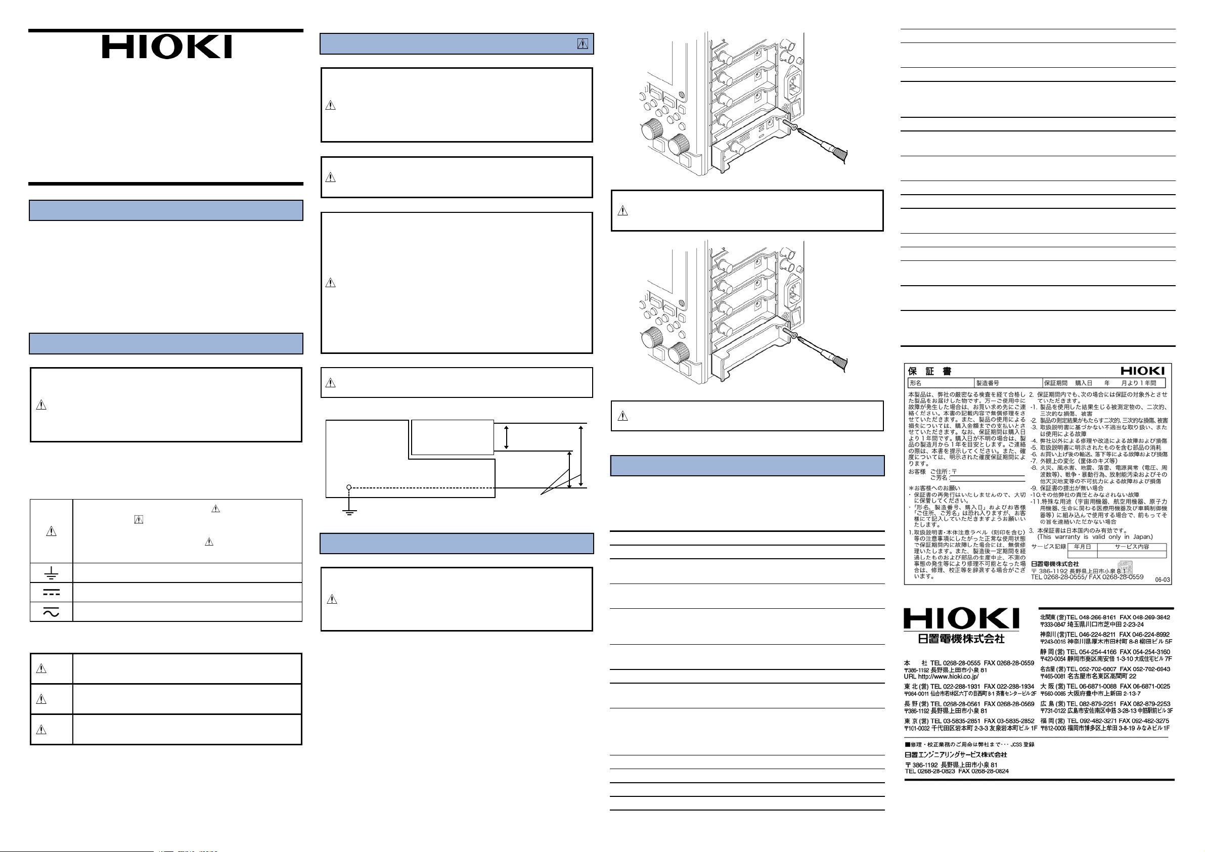
4. ユニットの交換方法
・感電事故を避けるため入力ユニットは、電源を
警告
・ここでは入力ユニットを取り外す方法を説明します。
・装着は、取り外した時の逆の順序で行います。
1.すべての入力ユニットの接続コードを外します。
2.本体の電源を OFF にして電源コードを抜きます。
3.図に従い入力ユニットを止めてある 2 つの固定ネジを+(プラス)
4.取っ手を持って引き抜きます。
すべての接続コードと電源コードを外してから追加・交換
してください。
・ネジ止めをしっかりしないと、仕様を満足しなかったり、故
障の原因になります。
ドライバーで外します。
9197,9198
H
DC400 Vmax
L
AC,DC370 V
OFF
を使用し
にし、
ブランクパネルを外したままで、測定しないでください。
注意
ユニット内の温度が不安定になるため、仕様を満足しません。
5. 仕 様
確度はメモリハイコーダに実装時 23±5℃,30〜80%rh
電源投入 30 分後にゼロアジャスト実行後にて規定
確度保証期間 1 年
測定レンジ
DC
振幅確度
ゼロポジション確度
温度特性
周波数特性
ノイズ
コモンモード除去比
ローパスフィルタ
アンチエイリアシン
グフィルタ
入力形式
入力結合
入力抵抗
入力容量
5,10,20,50,100,200,500 mV,1,2,5,10,20 V/DIV
±0.2%f.s.(フィルタ 5HzON,アベレージング時
±0.1%f.s.(フィルタ 5HzON,アベレージング時
ゼロアジャスト後)
ゲイン±0.025%f.s./℃
ゼロポジション±0.02%f.s./℃(ゼロアジャスト後)
DC〜100 kHz ±3dB(DC 結合時)
7Hz〜100 k Hz ±3dB(AC 結合時、低域カットオフ
周波数 7Hz±50%)
500μVp-p(typ ),1 mVp-p(max) 最高感度レンジ入
力短絡にて
80dB 以上(50/60 Hz 信号源抵抗 100 Ω以下)
OFF、5±50%、50±50%、500±50%、5k±50%、50 k
±50%(Hz)-3dB
カットオフ周波数(fc)20, 40, 80, 200, 400, 800, 2k
, 4k, 8k, 20k, 40k(Hz)
(アンチエリアシングフィルタ ON 時に自動設定)
減衰特性 1.5fc にて−66dB 以上
不平衡入力(フローティング)
AC/DC/GND
1MΩ±1%
40 pF±10 pF(100 kHz にて)
8953-10
Page 2
1. Introduction
Thank you for purchasing the HIOKI "8953-10 HIGH
RESOLUTION UNIT". To obtain maximum performance from
the device, please read this manual first, and keep it handy for
future reference.
The 8953-10 is the input module for the MEMORY HiCORDERs.
Always install this device on a Memory HiCORDER for use.
For the detailed installation procedure, refer to Main unit
manual.
Follow carefully the advice of "3. Notes on Use."
2. Safety Notes
DANGER
This device is designed to comply with IEC 61010 Safety
Standards, and has been thoroughly tested for safety prior
to shipment. However, mishandling during use could result
in injury or death, as well as damage to the device. Be
certain that you understand the instructions and
precautions in the manual before use. We disclaim any
responsibility for accidents or injuries not resulting directly
from device defects.
Safety symbol
This manual contains information and warnings essential for safe
operation of the device and for maintaining it in safe operating
condition. Before using the device, be sure to carefully read the
following safety notes.
The symbol printed on the device indicates that
the user should refer to a corresponding topic in
the manual (marked with the symbol) before
using the relevant function.
In the manual, the symbol indicates particularly
important information that the user should read
before using the device.
Indicates a grounding terminal.
Indicates DC (Direct Current).
Indicates both DC (Direct Current) and AC
(Alternating Current).
The following symbols are used in this Instruction Manual to
indicate the relative importance of cautions and warnings.
Indicates that incorrect operation presents an
DANGER
WARNING
CAUTION
extreme hazard that could result in serious injury
or death to the user.
Indicates that incorrect operation presents a
significant hazard that could result in serious
injury or death to the user.
Indicates that incorrect operation presents a
possibility of injury to the user or damage to the
device.
3. Notes on Use
DANGER
The maximum rated voltage to earth (voltage between
8953-10 input terminal and main unit frame, and between
input terminals of other high resolution units) is 370 V
AC/DC. To avoid the risk of electric shock and damage to
the device, take care that voltage between 8953-10 input
terminal and main unit frame, and between input
terminals of other high resolution units does not exceed
these ratings.
The maximum input voltage is 400 VDC. Attempting to
measure voltage in excess of the maximum input could
destroy the device and result in personal injury or death.
WARNING
The maximum rated voltage to earth rating applies also if
an input attenuator or similar is used.
When measuring voltages in power lines with high
current capability, always connect the probe to the
secondary side of the circuit breaker, to avoid the risk of
electric shock and damage to the device.
The power terminal is especially for use with the 9322
DIFFERENTIAL PROBE. Use the 9328 POWER CORD to
supply power to the 9322. To avoid personal injury or
damage to the device, do not connect anything except
the 9322 to the power terminal.
Before using the device, make sure that the insulation on
the connection cords is undamaged and that no bare
conductors are improperly exposed. Using the product in
such conditions could cause an electric shock, so
contact your dealer or Hioki representative for
replacements. (Model 9197 or 9198 CONNECTION CORD)
CAUTION
For safety reasons, only use the specified 9197 or 9198
CONNECTION CORD for measurement.
Main unit
GND
8953-10
HIGH
RESOLUTION
UNIT
H
400 VDCmax
L
370 VAC,DC
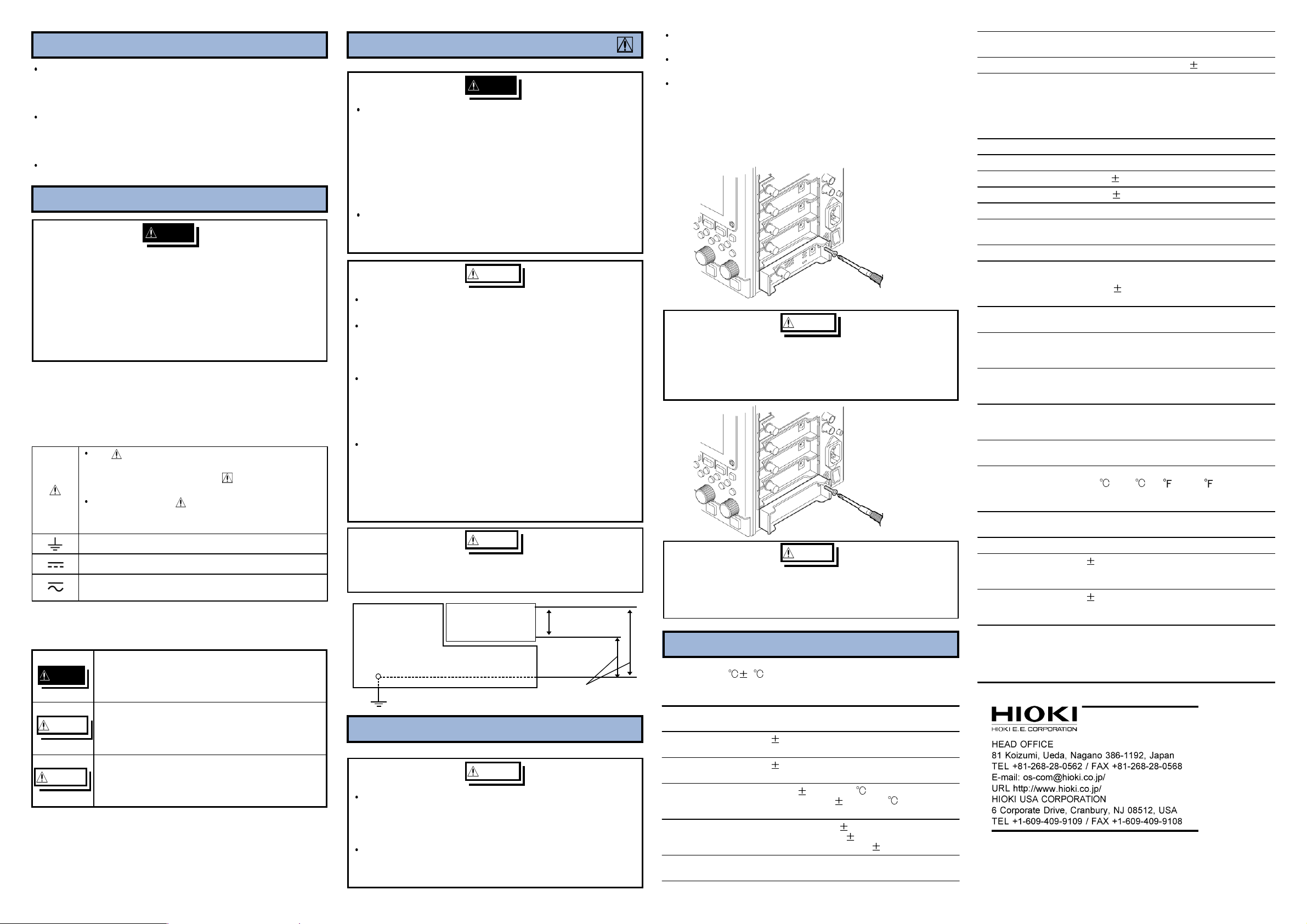
4. Replacement Procedure
WARNING
To avoid electric shock accident, before removing or
replacing an input module, confirm that the instrument is
turned off and that the all connection cords and power
cord are disconnected.
The mounting screws must be firmly tightened or the
input module may not perform to specifications, or may
even fail.
This section describes how to replace the 8953-10 HIGH
RESOLUTION UNIT.
The following procedure describes how to remove the input
moudle.
Install the devices by reversing the procedure for removal.
1. Remove the connection cords from all input modules.
2. Power off the main unit, and disconnect the power cord.
3. Remove the two fixing screws with a Phillips screwdriver, as
shown in the figure below.
4. Grasp the handle and pull the device out.
WARNING
To avoid the danger of electric shock, never operate the
instrument with an input module removed. To use the
instrument after removing an input module, install a blank
panel over the opening of the removed module.
CAUTION
Do not measure with a blank panel removed. Otherwise, the
device internal temperature becomes unstable and consequently
the specifications are not met.
5. Specifications
Accuracy at 23 5 , 30% to 80% RH after zero adjustment
after 30-minutes warming-up time. Accuracy guaranteed for 1
year.
Measurement ranges 5, 10, 20, 50, 100, 200, 500 mV/DIV
DC amplitude
accuracy
Zero position
accuracy
Temperature
characteristic
Frequency
characteristic
Noise 500 µVp-p typical, 1 mVp-p max.
1, 2, 5, 10, 20 V/DIV
0.2% f.s. (filter 5 Hz ON, averaging)
0.1% f.s. (filter 5 Hz ON, averaging,
after zero adjustment)
Gain: 0.025%f.s./
Zero position: 0.02%f.s./ (after zero
adjustment)
DC to 100 kHz 3 dB (DC coupling)
7 Hz to 100 kHz 3 dB (AC coupling, low
cut-off frequency: 7 Hz 50%)
(sensitivity range, with input shorted)
Common mode
rejection ratio
Low-pass filter OFF,5,50,500,5 k,50 k 50% (Hz) -3 dB
Anti-aliasing filter Cutoff frequency (fc) : 20, 40, 80, 200,
Input type Unbalanced (floating)
Input coupling AC, DC, GND
Input resistance 1MΩ 1%
Input capacitance 40 pF 10 pF (at 100 kHz)
A/D resolution 16 bits
Maximum sampling
speed
Input terminals BNC terminal
Power supply terminal Especially for use with the 9322
Maximum input
voltage
Insulation resistance,
Withstand voltage
Maximum rated
voltage to earth
Operational ranges for
temperature and
humidity
Operating
Environment
Temperature and
humidity ranges for
storage
Dimensions Approx. 107.4 W x 28 H x 164.5 D mm
Mass Approx. 150 g (5.3 oz.)
Effect of radiated
radio-frequency
electromagnetic field
Effect of conducted
radio-frequency
electromagnetic field
Standard Applying
Safety
EMC
September 2006 Revised edition 2
8953B980-02 06-09H Printed in Japan
80 dB minimum (at 50/60 Hz and with
signal source resistance 100 Ω maximum)
400, 800, 2 k, 4 k, 8 k, 20 k, 40 k (Hz)
These frequencies are automatically set
when the anti-aliasing filter is set to ON.
Attenuation characteristic: -66 dB, min. (at
1.5 fc)
1 MS/s
DIFFERENTIAL PROBE
+12 V 8% (Shares the ground of power
terminals of other mounted modules.)
400 V DC max.
Amplifier - Main unit, each amplifier: 3.7
kV AC for 1 minute
100 MΩ or over / 500 V DC
370 V max. AC/DC (between each input
channel and main unit, and between input
channels)
Same as the Memory HiCorder in which
the 8953-10 is installed
Same as the Memory HiCorder in which
the 8953-10 is installed
Temperature:
-10 to 50 (14 to 122 )
Relative humidity: 80% RH maximum (with
no condensation)
(4.23" W x 1.10" H x 6.48" D)
15% f.s. at 3V/m (max.)
2% f.s. at 3V (max.)
EN 61010 Pollution Degree 2,
measurement category II
(anticipated transient overvoltage 4000 V)
EN 61326, Class A
 Loading...