

Page 1
8910
CAN ADAPTER
Instruction Manual
Aug. 2018 Revised edition 7
8910A981-07 18-08H
EN
Page 2

Page 3

Contents
Contents
Introduction.................................................................................1
Inspection...................................................................................1
Safety Notes............... .. ............................... ...............................4
Notes on Use.. .. .. ................................ ............................... .........7
Chapter 1
Product Overview __________________________ 11
1.1 Overview .....................................................................11
1.2 Major Feature s..... .. ... ............................... ...................12
1.3 Identification of Controls and Indicators......................13
i
Chapter 2
Preparation________________________________ 15
2.1 Installation o f th e In st r ument.......... ... .. ........................15
2.2 Power Supply Co n ne ct i o ns... .. .. ... ...............................16
2.2.1 Connecting the AC adapter ...........................................16
2.2.2 Connecting the DC Power Supply .................................17
2.3 Connection Procedure ................................................18
2.4 Power On/Of f .. .. ............................. ... .. ........................21
Chapter 3
Operation _________________________________ 23
3.1 Modes .........................................................................23
3.2 Conversion Mode........................................................23
3.3 Setting Mode...............................................................24
3.3.1 Activating setting mode .................................................25
3.3.2 Contents of display in setting mode ..............................26
3.3.3 Selecting a channel number ..........................................26
3.3.4 Selecting the CAN definition data to be output ..............27
3.3.5 Setting the D/A conversion format/logic bit position ......28
3.3.6 Returning to conversion mode ......................................29
8910A981-07
3.4 Calibration Mo de.. .. ... ..................................................30
3.4.1 Activating calibration mode ...........................................30
3.4.2 Selecting a channel number ..........................................31
3.4.3 Outputting a calibration signal .......................................31
3.4.4 Returning to conversion mode ......................................32
3.5 Operation Map ............................................................33
Page 4

ii
Contents
Chapter 4
Preparation of the CAN Set Program ___________37
4.1 Overview..................................................................... 37
4.2 Program Setup ........................................................... 38
4.2.1 System requirements ................................................. ...38
4.2.2 Installation .....................................................................38
4.2.3 Un-Installation ............................................................... 39
Chapter 5
Starting the CAN Set Program ________________41
5.1 Connecting the PC to the 8910 .................................. 41
5.2 Starting Up the Condition Setting Program ................42
5.3 Menu Items in the Setting Window.............................45
5.4 Operation Flowchart................................................... 46
Chapter 6
Setting the CAN Definition Data _______________49
6.1 Opening a CAN definition data file ............................. 49
6.1.1 Opening a CAN definition data file ................................49
6.1.2 Creating a new CAN definition data file ........................50
6.2 Editing the CAN Definitio n Data .......... .. ................. .. .. 52
6.2.1 Setting the message ID ............................................. ...53
6.2.2 Setting the data length ..................................................53
6.2.3 Setting the data start position .......................................54
6.2.4 Setting the data pattern .................................... .... ..... ...55
6.2.5 Setting the sign ..................... .... ..... ............................ ...56
6.2.6 Setting the signal name ................................................57
6.2.7 Setting the label name ..................................................57
6.2.8 Setting the unit .......................... ..... ..... ..........................57
6.2.9 Setting the scaling ............................................ .... ..... ...58
6.2.10 Error Massage ..............................................................60
6.3 Deletion of CAN Definition Data................................. 61
6.4 Closing the CAN Definition Data File
(Saving the File) ......................................................... 62
6.5 CAN Definition Data List Detail Display...................... 63
6.6 Editing in Another Window.........................................65
6.6.1 Opening a new window ................................ ..... ............65
6.6.2 Creating a new CAN definition data file ........................69
6.6.3 Opening a CAN definition data file ................................69
6.6.4 Editing CAN definition data ...........................................69
6.6.5 Saving CAN definition data ...........................................69
Page 5

Contents
Chapter 7
Settings___________________________________ 71
7.1 Registration List Operations........................................71
7.1.1 Opening a registration list ..............................................71
7.1.2 Creating a registration list (registering definition data
to a registration list) .......................................................72
7.1.3 Deleting data from the registration list ...........................74
7.2 Allocation to Output Channels.....................................75
7.2.1 Setting analog output channels .....................................75
7.2.2 Del eting registere d data from the analog output
allocation list ..................................................................76
7.2.3 Setting logic output channels ........................................77
7.2.4 Deleting data from the logic output allocation list ..........78
7.3 Massage ID Trigger.............................. ...................... .79
7.3.1 Setting the message ID trigger ......................................79
7.3.2 Setting output channels .................................................80
iii
7.4 Setting the ID Filter ... ............................... ...................81
Chapter 8
Transfer of Setting Data to the 8910 ___________ 83
8.1 Setting Communication Parameters ...........................83
8.2 Executing Data Transfer .............................................84
8.3 In Case of Errors....... .. ................. ................. ..............8 5
8.4 Duplicate Bit Check.....................................................86
Chapter 9
Functions of the Setting Program _____________ 87
9.1 Saving the Sett ing Da ta .................... ................ ..........87
9.1.1 Saving data with a new name .......................................87
9.1.2 Overwriting ....................................................................88
9.2 Setting Data Printout...................................................89
9.2.1 Printing ..........................................................................89
9.2.2 Print preview .................................................................89
9.2.3 Setting the printer ..........................................................90
9.2.4 Examples of printouts ....................................................90
9.3 Displaying Windows............................................ ........92
9.4 Password Setting ........................................................93
9.5 Version Chec k.............................. .. ... ..........................94
Page 6

iv
Contents
Chapter 10
Connection to Memory HiCorder ______________95
10.1 Using the 8910 with the 8826 MEMORY HiCORDER 96
10.1.1 Displaying the 8910 setting screen ...............................96
10.1.2 8910 setting screen ................................................... ...98
10.1.3 Setting the block no. .....................................................99
10.1.4 Setting analog channel output ....................................100
10.1.5 Setting logic channel output ........................................102
10.1.6 Displaying the registration list .....................................103
10.1.7 Communication between the 8826 and 8910 .............104
10.1.8 Downloading an setting data file .................................107
10.2 Using the 8910 with the 8841, 8842 MEMORY
HiCORDER............................................................... 109
10.2.1 Displaying the 8910 setting screen .............................109
10.2.2 8910 setting screen ................................................... .111
10.2.3 Setting the block no. ...................................................112
10.2.4 Setting analog channel output ....................................113
10.2.5 Setting logic channel output ........................................115
10.2.6 Displaying the registration list .....................................116
10.2.7 Communication between the 8841, 8842 and 8910 ...117
10.2.8 Downloading a setting data file ...................................120
Chapter 11
Specifications_____________________________123
11.1 General Specifications..............................................123
11.2 Specifications of Functions....................................... 125
11.3 Specifications of 8910 CAN Set Program
(PC Application)........... .. ............................... ............ 126
11.4 Specifications of CAN Setting Function
(for Memory HiCorder).............................................. 127
11.5 Accessories.............................................................. 128
11.6 Options..................................................................... 128
11.6.1 9713-01 CAN CABLE (one end unprocessed) ...........129
11.6.2 9713-02 CAN CABLE (For automotive connector) .....130
11.6.3 9714-01 LOGIC CABLE (one end unprocessed) ........131
11.6.4 9714-02 LOGIC CABLE (for Memory HiCorder) .........1 32
11.7 Specifications of Connectors....................................133
Page 7

Contents
Chapter 12
Maintenance and Service ___________________ 135
12.1 Service and Cleaning................................................135
12.2 Troubleshooting ........................................................135
v
Page 8

vi
Contents
Page 9
Introduction
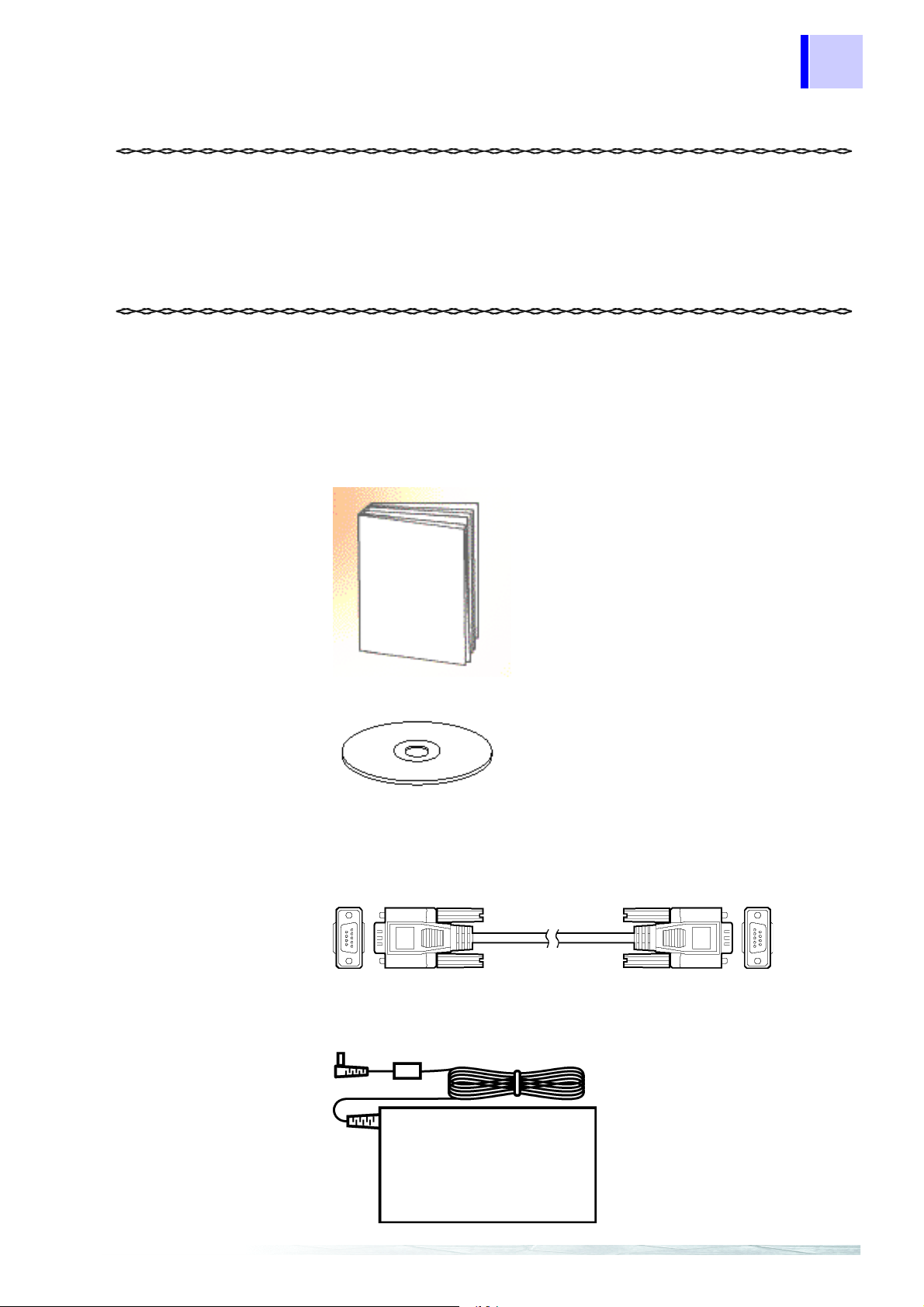
Instruction manual.....................................1
CD-R ("8910 CAN set program" software
(Japanese/English 2 files) (for PC),
CAN
setting function (for Memory Hi Co rder)).... 1
RS-232C cable (D-sub 9-pin, male-female,
straight cable ) (Approx. 1.8 m ).... .............. 1
9418-15 AC ADAPTER ............................1
Inspection
1
Introduction
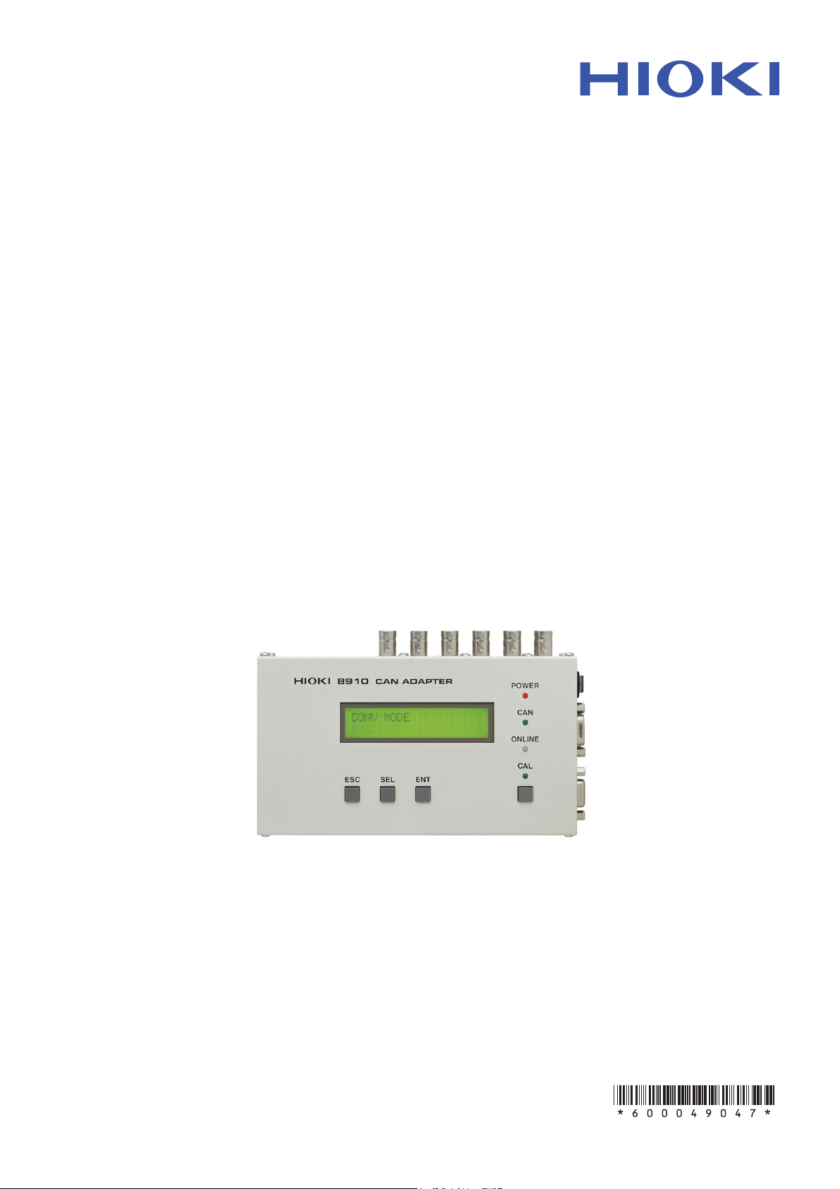
Thank you for purchasing the HIOKI “Model 8910 CAN ADAPTER”. To
obtain maximum performance from the instrument, please read this
manual first, and keep it handy for future reference.
When you receive the instrument, inspect it carefully to ensure that no
damage occurred during shipping. In particular, check the
accessories, panel switches, and connectors. If damage is evident, or
if it fails to operate according to the specifications, contact your dealer
or Hioki representative.
Accessories
Page 10
2
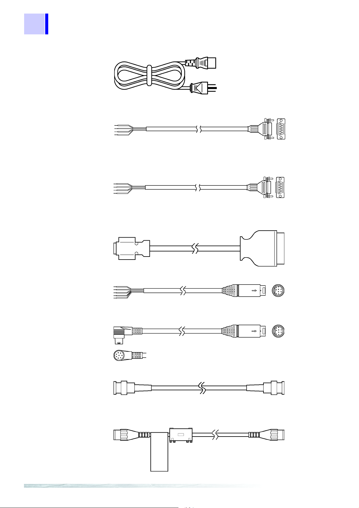
Power cord .... ............................................1
9713-01 CAN CABLE (one end
unprocesse d ) (A p p r ox. 2 m)....... ............. ..1
9713-01 CAN CABLE (one end unprocessed) (Approx. 2 m)
9713-02 CAN CABLE (For automotive connector) (Approx. 2 m)
(Since this part is made to order, check the specifications document
and delivery date.)
9714-01 LOGIC CABLE (one end unprocessed) (Approx. 1.5 m)
9714-02 LOGIC CABLE (for Memory HiCorder) (Approx. 1.5 m)
9165 CONNECTION CORD (Metal BNC - Metal BNC) (Approx. 1.5 m)
L9217 CONNECTION CORD (Metal BNC - Insulated BNC)
(Insulated BNC for Memory HiCorder) (Approx. 1.7 m)
Inspection
Options
Page 11
Inspection
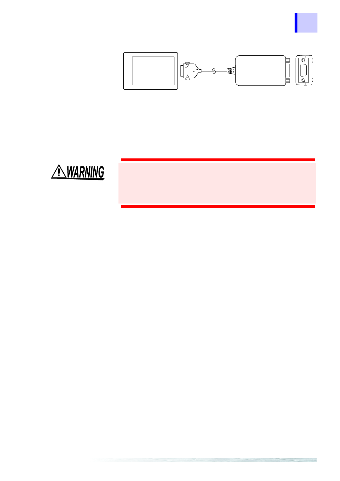
9557 RS-232C CARD (for Memory HiCorder)
Preliminary Checks
Before using the instrument the first time, verify that it operates
normally to ensure that the no damage occurred during storage or
shipping. If you find any damage, contact your dealer or Hioki
representative.
Before using the instrument, make sure that the insulation on the
cords and cables are undamaged and that no bare conductors
are improperly exposed. Using the product in such conditions
could cause an electric shock, so contact your dealer or Hioki
representative for repair.
3
Page 12
4
Safety Notes
Safety Notes
Safety symbols
This instrument is designed to comply with IEC 61010 Safety
Standards, and has been thoroughly tested for safety prior to
shipment. However , mishandli ng duri ng use could r esult in inj ury
or death, as well as damage t o the inst rument. Be ce rtain that you
understand the instructions and precautions in the manual
before use. We disclaim any responsibility for accidents or
injuries not resulting directly from instrument defects.
This manual contains information and warnings essential for safe
operation of the instrument and for maintaining it in safe operating
condition. Before using it, be sure to carefully read the following safety
precautions.
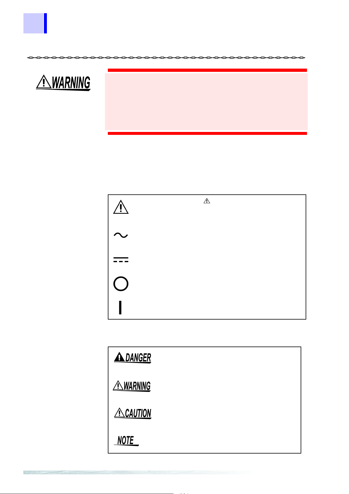
In the manual, the symbol indicates particularly
important information that the user should read before
using the instrument.
Indicates AC (Alternating Current) .
Indicates DC (Direct Current).
Indicates the OFF side of the power switch.
Indicates the ON side of the power switch.
The following symbols in this manual indicate the relative importance
of cautions and warnings.
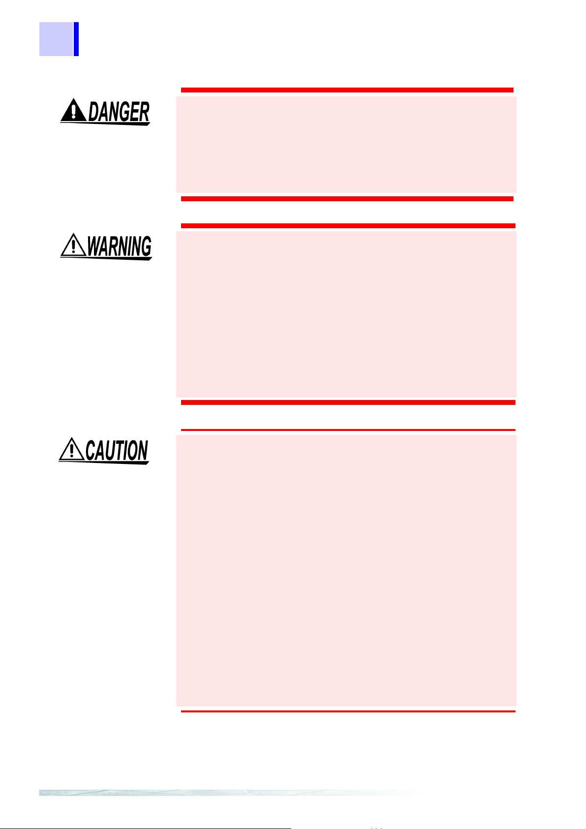
Indicates that incorrect operation presents an
extreme hazard that could result in serious injury
or death to the user.
Indicates that incorrect operation presents a
significant hazard that could result in serious
injury or death to the user.
Indicates that incorrect operation presents a
possibility of injury to the user or damage to the
instrument.
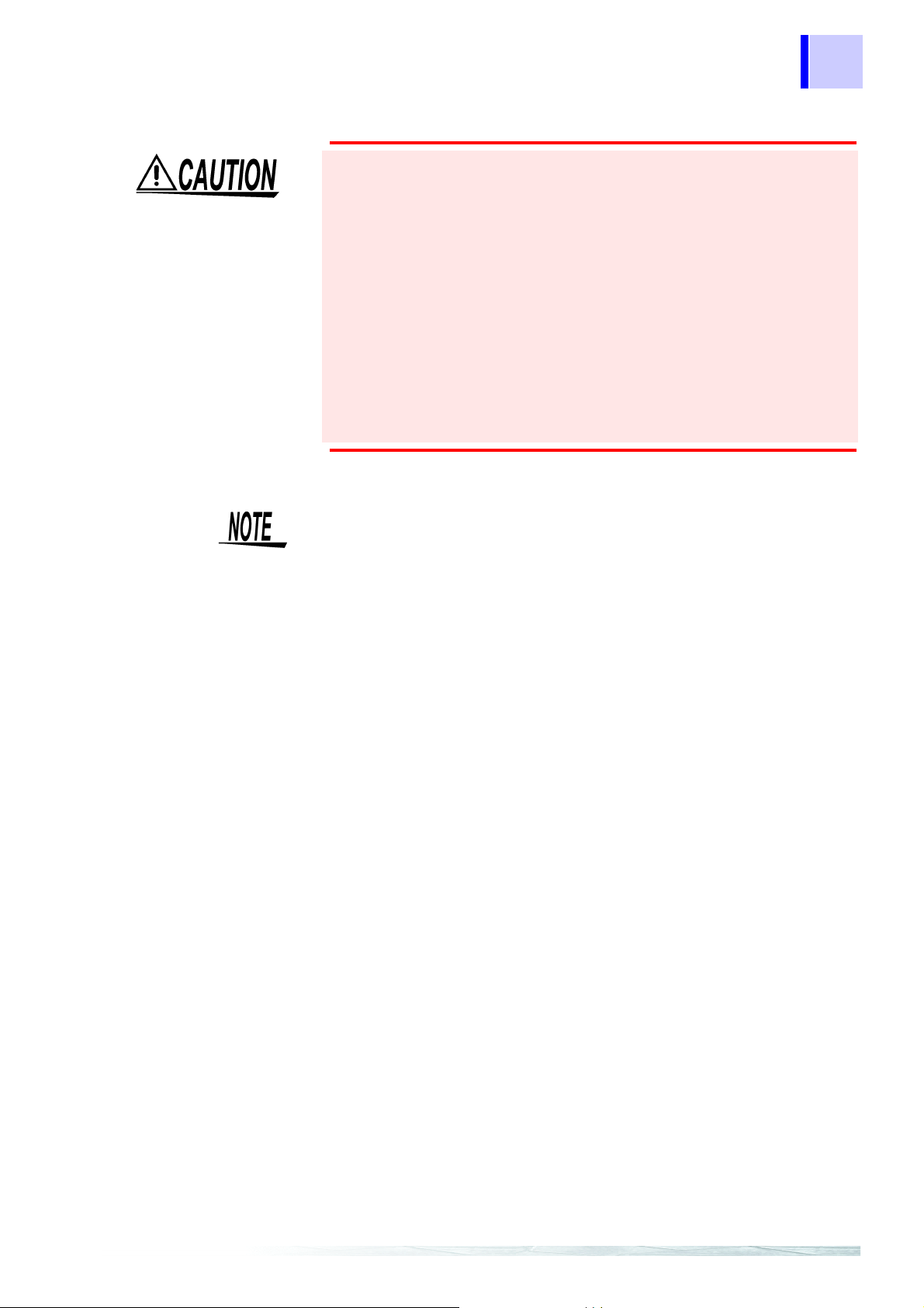
Indicates advisory items related to performance
or correct operation of the instrument.
Page 13

Mouse Operation
5
Safety Notes
Indications
Click :
Right-click :
Double click :
Drag :
Activate :
Press and quickly release the left button of the mouse.
Press and quickly release the right button of the
mouse.
Quickly click the left button of the mouse twice.
While holding down the left button of the mouse, move
the mouse and then release the left button to deposit
the chosen item in the desired position.
Click on a window on the screen to activate that
window.
• Unless otherwise specified, “Windows” represents Windows 95, 98,
Me, Windows NT4.0, Windows 2000, or Windows XP.
• Dialogue box represents a Windows dialog box.
• Menus, commands, dialogs, buttons in a dialog, and other names
on the screen and the keys are indicated in brackets.
Page 14

6
Safety Notes
Measurement categories
To ensure safe operation of measurement instruments, IEC 61010
establishes safety standards for various electrical environments,
categorized as CAT II to CAT IV, and called measurement categories.
These are defined as follows.
CAT II : Primary electrical circuits in equipment connected to an AC
CAT III : Primary electrical circuits of heavy equipment (fi xed
CAT IV: The circuit from the service drop t o the service entrance, and
Using a measurement instrument in an environment designated with a
higher-numbered category than that for which the instrument is rated
could result in a severe accident, and must be carefully avoided.
Use of a measurement instrument that is not CAT-rated in CAT II to
CAT IV measurement applications could result in a severe accident,
and must be carefully avoided.
electrical outlet by a power cord (portable tools, household
appliances, etc.)
CAT II covers directly measuring electri cal outlet receptacles.
installations) connected directly to the distributi on panel, and
feeders from the distribution p anel to outlets.
to the power meter and primary overcurrent pr otection device
(distribution panel).
Page 15

Notes on Use
Notes on Use
Follow these precautions to ensure safe operation and to obtain the
full benefits of the various functions.
Connecting the Cables (RS-232C Cabl e, CAN Cable,
Connection Cord [Analog], Logic Cabl
The ground (GND) conductors of the connecting cables* connect
in common to the Model 8910 chassis ground (they are not
isolated). Care is therefore necessary to ensure that there is no
potential difference between the instrument chassis ground and
the ground of any connecting device. Otherwise, the instrument
or connecting device could be damaged. Refer to “Power
Sources” below.
Power Sources
The ground (GND) conductors of connecting cables* connect in
common to the Model 8910 chassis ground (they are not
isolated). Therefore, supplying power from different sources to
the instrument and a connecting device could cause electric
shock and equipment damage. To avoid these hazards, power
should always be supplied from the same source.
Even when power is supplied from the same source, as a result
of wiring, potential difference between grounds can result in
current flow through the connecting cables* that could damage
the equipment.
To avoid such hazards, we recommend observing the following
precautions for power connections:
) When poweri
(1
before connecting devices to the 8910, plug the (supplied)
grounded power cord of the AC adapter into the same outlet
as that used to power the devices to be connected.
ng the 8910 from the supplied AC adapter,
e)
❖ 2.2.1 Connecting the AC adapter (Page 16) and
2.3 Connection Procedure (Page 18)
) W
(2
hen powering the 8910 from a DC power source, before
making other connections, first connect the ground of the
8910 to the grounds of the devices to be connected. In this
case, always use the same power source.
❖ 2.2.2 Connecting the DC Power Supply (Page 17) and
2.3 Connection Procedure (Page 18)
) W
(3
hen powering the 8910 from the supplied AC adapter and
powering connecting devices from a DC source (or when
powering the 8910 from DC and connecting devices from
AC), before making other connections to the 8910, first
connect the ground of the 8910 to the grounds of the
devices to be connected. Refer to the following alternatives
regarding common ground connection methods.
) Connect
(a
the AC adapter’s ground.
) Conn
(b
the ground of the device to be connected.
the grounds of devices running on DC power to
ect pin 3 (CAN_GND) of the 9713-01 CAN Cable to
7
*Connecting cables: Cables and connection cords being connected to the 8910.
Page 16
8
Notes on Use
Note: In method (b) above, because of wire length and CAN cable
wiring conditions, some potential difference may remain
between grounding points, so we recommend (a) as the
preferred method.
❖ 2.2.1 Connecting the AC adapter (Page 16),
2.2.2 Connecting the DC Power Supply (Page 17) and
2.3 Connection Procedure (Page 18)
Power Supply Connections
Before turning the instrument on, make sure the supply voltage
matches that indicated on the its power connector. Connectio n to
an improper supply voltage may damage the instrument and
present an electrical hazard.
Grounding the Instrument
To avoid electrical accidents and to maintain the safety
specifications of this instrument, connect the power cord
provided only to a 3-contact (two- conductor + ground) outlet.
❖ 2.2 Power Supply Connections (Page 16)
Before Powering on
Check the power supply is correct for the rating of the unit.
Usage Precautions for the CD-R
• Always hold the disc by the edges, so as not to make fingerprints on
the disc or scratch the printing.
• Never touch the recorded side of the disc. Do not place the disc
directly on anything hard.
• Do not wet the disc with volatile alcohol or water, as there is a
possibility of the label printing disappearing.
• To write on the disc label surface, use a spirit-based felt pen. Do not
use a ball-point pen or hard-tipped pen, because there is a danger of
scratching the surface and corrupting the data. Do not use adhesive
labels.
• Do not expose the disc directly to the sun's rays, or keep it in
conditions of high temperature or humidity, as there is a danger of
warping, with consequent loss of dat a.
• To remove dirt, dust, or fingerprints from the disc, wipe with a dry
cloth, or use a CD cleaner. Always wipe radially from the inside to
the outside, and do no wipe with circular movements. Never use
abrasives or solvent cleaners.
• Hioki shall not be held liable for any problems with a computer
system that arises from the use of this CD-R, or for any problem
related to the purchase of a Hioki product.
Page 17
Notes on Use
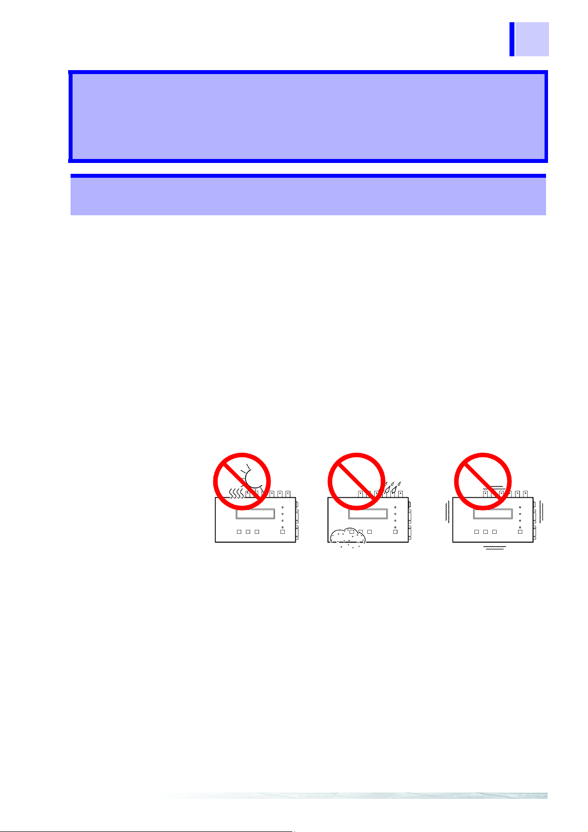
Installation Environment
• Do not use the instrument where it may be exposed to corrosive or
combustible gases. The instrument may be damaged.
• The instrument should be installed and operated indoors only,
between -10 and 55°C and 30 to 80% RH.
• Do not store or use the instrument where it could be exposed to
direct sunlight, high temperature or humid ity, or condensation. Under
such conditions, the instrument may be damaged and in sulation may
deteriorate so that it no longer meets specifications.
Others
• To prevent an electric shock accident, confirm that the white or red
portion (insulation layer) inside the cable is not exposed. If a color
inside the cable is exposed, do not use the cable.
• Carefully read and observe all precautions in thi s manual.
9
• Using an connection cord other than that specified by HIOKI may
damage the BNC connector or result in measurement errors due to
contact failure.
• Even when using the 8910 within the permitted operating temperature
(-10 to 55°C) and humidity ranges, display on the LCD may become
difficult to read at very low o r high amb ient temperatures . (In such cas e,
alter the viewing angle.) Note that this change does no t affect instrume nt
operation.
•This
instrument may cause interference if used in residential areas.
Such use must be avoided unless the user takes special me asures to
reduce electromagnetic emissions to prevent interference to the
reception of radio and television broadcasts.
Page 18

10
Notes on Use
Page 19

roduct
P
Overview Chapter 1
1.1 Overview
• 8910 CAN ADAPTER is a signal converter that acquires necessary
• The type of data to be acquired is set by using a PC, with settings
• Internal memory can store up to 50 items of CAN definition data.
11
1.1 Overview
signals from CAN signals flowing on a CAN bus, converts the
signals to analog or logic signals, then genera tes out put.
transferred and saved in internal memory of the 8910 via the RS232C.
Since you can change allocated output channels by using the LCD
and operation keys on the f ront panel, the instr ument can be used i n
various applications without a PC.
Page 20

12
1.2 Major Features
1.2 Major Features
1. Compact size and lightweight
The main unit is compact and lightweight for easy portability.
2. Ample output channels
The 8910 is equipped with ample output channels - 12 channels for
analog signal output and 24 bits for logic signal output.
3. Two independent input ports
Since CAN1 and CAN2 are independent, two networks with different
baud rates can be connected.
4. Automatic baud rate setting
Because the 8910 monitors the CAN bus and automatically sets the
baud rate, there is no need to manually set the baud rate. (Supported
baud rates are 125 kbps, 250 kbps, 500 kbps, and 1 Mbps.)
5. Detailed settings using a PC
Easy-to-use PC application software enables the detailed settings of
data to be acquired from a CAN bus.
6. Observation with your existing recorder
The output signal level ranges from -5 to +5 V, and the value is held
until subsequent signal output. Therefor e, output from the 8910 can be
connected to an ordinary recorder. Thus, you can observe CAN
signals by connecting the 8910 to your existing recorder.
7. Real-time output
CAN signals are converted into analog/logic signals and output in real
time.
8. Mixed recording
By using the 8910 with a recorder such as the Memory HiCorder,
"sensor data or control signal on CAN" and "signal that cannot be
acquired on CAN" can be recorded together.
Page 21
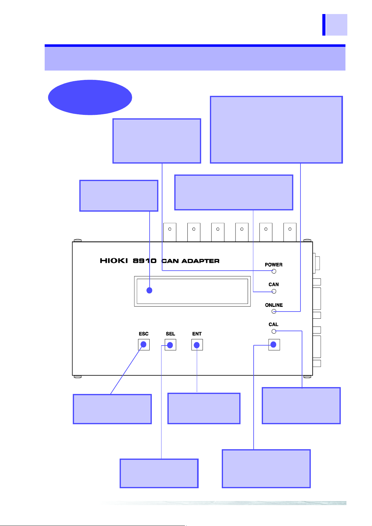
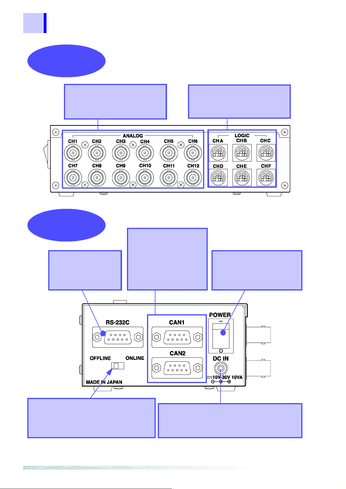
1.3 Identification of Controls and Indicators
Front Side
LCD display
20 characters x 2 lines,
with backlight
Power LED
The LED indicates the power
ON status of the instrument.
The LED goes on in red when
power is turned on.
CAN LED
The LED goes on in green when the
CAN message assigned to the 8910's
output channel is input.
Online LED
This LED indicates whether the 8910 and PC
can communicate via the RS-232C.
The LED goes on in green when the ONLINE/
OFFLINE switch is set to the ONLINE side for
enabling communication.
The LED goes on in orange when the 8910 is
engaged in communication.
ESC (escape) key
Key used for various
settings.
SEL (select) key
Key used for various
settings.
ENT (enter) key
Key used for various
settings.
CAL (calibration) key
In calibration mode, a
calibrat ion signal is output
only while this key is pressed.
CAL LED
The LED goes on in green
during calibration signal
output.
13
1.3 Identification of Controls and Indicators
Page 22
14
Back Side
Analog Output Terminals
These terminals output analog
signals. All 12 channels use BNC
connectors.
Logic Output Terminals
These terminals output logic signals.
Each terminal outputs 4 bits, for a
total of 24 bits.
Right Side
RS-232C Terminal
This is a communication
connector for connect ing
a host PC or Memory
HiCorder.
CAN Input Ports 1, 2
These ports are CAN signal
input terminals. Since CAN1
and CAN2 are independent,
two different networks can be
connected. These ports can
also be used to supply power
to the 8910.
Power Switch
This switch turns the power ON
and OFF. The switch is effective
for power supplied through
DCIN, CAN1, and CAN2.
AC adapter connection Terminal
This terminal is used to connect the AC ADAPTER.
(A DC power supply (10 to 30 V) can also be
connected.)
ONLINE/OFFLINE Switch
This switch is used to set the 8910 to ONLINE
or OFFLINE mode. Setting this switch to
ONLINE enables the 8910 to communicate
with the host PC or Memory HiCorder.
Key lock: Note that the 8910 accepts no key entry when the [
ONLINE/OFFLINE] switch is set to the
[
ONLINE] side.
1.3 Identification of Controls and Indicators
Page 23
2.1 Installation of the Instrument
Preparation Chapter 2
2.1 Installation of the Instrument
1. Installation orientation
Install the instrument on a flat, level surface.
2. Ambient conditions
• Temperature : -10 to 55°C
• Humidity : 30 to 80%RH (with no condensation)
15
3. Do not us e the instrument in the following locations:
• Subject to direct sunlight.
• Subject to high levels of dust, steam, or corrosive gases (Avoid
using the equipment in an environment containing corrosive gases
(e.g., H
gasses (e.g., organic silicones, cyanides, and formalins).
• Subject to vibrations.
• In the vicinity of equipment generating strong electromagnetic fi elds.
2S, SO2, NI2, and CI2) or substances that generate harmful
Page 24

16
2.2 Power Supply Connections
2.2 Power Supply Connections
2.2.1 Connecting the AC adapter
• Use only the supplied Model 9418-15 AC ADAPTER . AC
adapter input voltage range is 100 to 240 VAC (with ±10%
stability) at 50/60 Hz. To avoid electrical hazards and damage to
the instrument, do not apply voltage outside of this range.
• To avoid electrical accidents and to maintain the safety
specifications of this instrument, connect the power cord only
to a 3-contact (two-conductor + ground) outlet.
Connect the A C adapter to the 8910 .
1
Connect the AC adapter plug to an outlet.
2
Page 25

2.2 Power Supply Connections
2.2.2 Connecting the DC Power Supply
In addition to the AC adapter, any of the following power sources can
be used:
• DC power supply (10 to 30 V) (Voltage fluctuations of ±10% from
the rated supply voltage are taken into account.)
• Power supplied from CAN input port (10 to 30 V) (Voltage fluctuations
of ±10% from the rated supply volt age are t ak en into account.)
17
Page 26
18
Earth
Power
Outlet
Connecting
cables
8910
AC
adapter
Device to be
coneected
GND
Connecting
Cables
DC pow er so urce
(Battery or equiv.)
+
-
Devic e to be
connected
+
-
8910
+
-
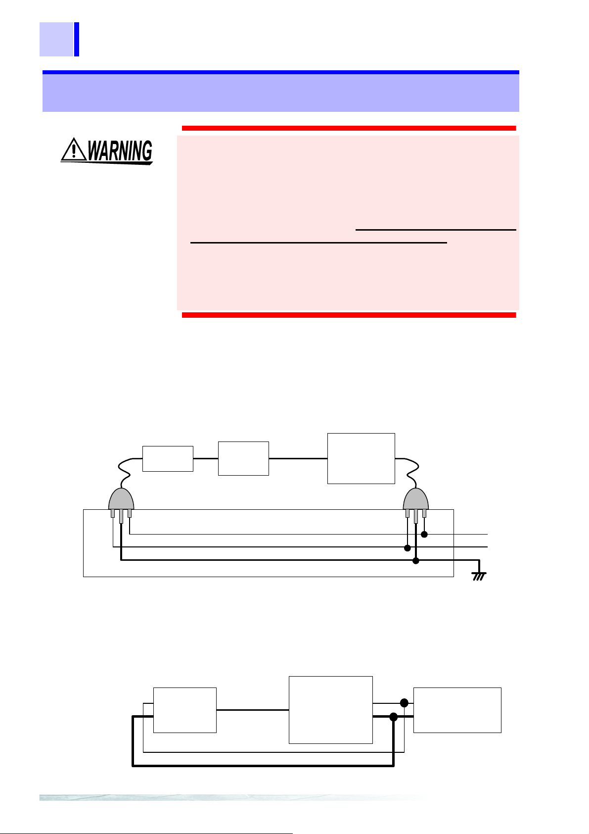
2.3 Connection Procedure
2.3 Connection Procedure
• To avoid the risk of electric shock, never connect the
connecting cables
• The ground (GND) conductors of connecting cables
in common to the Model 8910 chassis ground (they are not
isolated). Therefore, supplying power from different sources to
the instrument and a connecting device could cause electric
shock and equipment damage. To avoid these hazards, power
should always be supplied from the same source.
Even when power is supplied from the same source, as a result
of wiring, potential difference between grounds can result in
current flow through the connecting cable that could damage
the equipment. To avoid such hazards, we recommend
observing the following precautions for power connections:
*
of energized equipment to the 8910.
*
connect
*Connecting cables: Cables and connection cords being connected to the 8910.
Recommended Connection Procedures
(1) When powering the 8910 from the supplied AC adapter
Before connecting devices to the 8910, plug the (supplied) grounded
power cord of the AC adapter into the same outlet as that used to
power the devices to be connected.
(2) When powering the 8910 from a DC power source
Before making other connections, first connect the ground of the 8910
to the grounds of the devices to be connected. In this case, always
use the same power source.
Page 27

19
Earth
Power
Outlet
GND
9713-01
7 pin (CAN_H)
2 pin (CAN_L)
9 pin (CAN_V+)
3 pin (CAN_GND)
(b)
(a)
AC
adapter
DC power
(Battery or equiv.)
8910
+
-
Device to be
connected
+
-
2.3 Connection Procedure
(3) When powering the 8910 from the supplied AC adapter and
powering connecting devices from a DC source (or when
powering the 8910 from DC and connecting devices from AC)
Before making other connections to the 8910, first connect the ground
of the 8910 to the grounds of the devices to be conne cted. Refer to t he
following alternatives regarding common ground connection methods.
(a) Connect the grounds of devices running on DC power to the AC
adapter’s ground.
(b) Connect pin 3 (CAN_GND) of the 9713-01 CAN Cable to the
ground of the device to be connected.
Note: In method (b) above, because of wire length and CAN cable
wiring conditions, some potential difference may remain
between grounding points, so we recommend (a) as the
preferred method.
Page 28
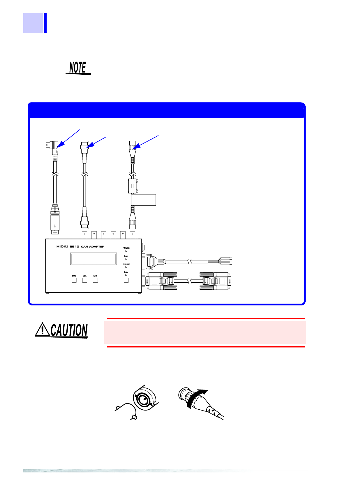
20
Connection Points
The 9714-01 or 9714-02 LOGIC CABLE (This is the 9714-02)
The 9165 or L9217 CONNECTION CORD
The 9713-01 or 9713-02 CAN CABLE
(This is the 9713-01)
RS-232C Cable
Lock
2.3 Connection Procedure
The following diagram shows the connection points of the cables and cords to
be connected to the 8910 CAN ADAPTER.
The instrument does not output signals (including response bits) to the CAN
bus. Therefore, when onl y one device connected to the bus in additio n to
the 8910, communication is not possible since response bits cannot be
exchanged. Therefore, be sure to connect the bus to which the 8910 is
connected with two or more devices to enable communication.
To prevent an electric shock accident, confirm that the white or
red portion (insulation layer) inside the cable is not exposed. If a
color inside the cable is exposed, do not use the cable.
Connecting to the Analog Output
1. Align the BNC connector with the guide groove of the unit output
connector, and turn clock wise while pressing in to lock the connector.
2. To remove from the instrument, turn the BNC connector
counterclockwise to release the lock, then pull it.
Page 29
2.4 Power On/Off
HIOKI
8910CANADAPTER
8910CANADAPTER
VerX.XX
CONVMODE
Error Massages
Err:ASSIGNCH
NOTFOUND
Err:ASSIGNLIST
NOTFOUND
<When no CAN data is registered> <When no CAN data is assigned to
an output channel>
Check the following points before the power switch is turned on.
• When using the AC adapter, make sure that the power supply
complies with the rated voltage (100 - 240 VAC) and rated
frequency (50/60 Hz) of the 8910.
• The instrument is correctly connected.
❖ (Section 2.1, 15p.)
Connect the cables and cords.
1
Connect cables and cords before turning on the power.
21
2.4 Power On/Off
Turn on the power.
2
When the power switch is turned on, the POWER LED goes on.
Confirm that the above display appears. (X.XX is the version No.)
The 8910 then begins internal initialization.
3
When initialization is complete, the display bellow appears and the
instrument enters CAN signal conversion mode.
Note that if no CAN data has been registered or assigned to any
output channel, the following error message will flash on the display:
Page 30

22
2.4 Power On/Off
• The error message continues flashing unti l a key is pressed.
• While the error message is displayed, RS communication is
disabled. To conduct RS communication, press any key to place
the instrument in conversion mode.
Page 31

3.1 Modes
CONVMODE
Operation Chapter 3
3.1 Modes
The 8910 has the following three operation modes, which can be
switched by using keys on the front panel.
23
Conversion mode
Setting mode
Calibration mode
3.2 Conversion Mode
• Conversion mode is the first mode to become active after power is
turned on.
• This mode converts the CAN message supplied to CAN1 or CAN2
port according to internally set definition data, and outputs the
converted signal from a specified analog or logic output terminal.
This mode converts the CAN signal input from
the CAN 1 or 2 port according to the set
definition data, and outputs the converted
signal from the specified analog or l ogic outpu t
terminal.
This mode is used to select data to be
acquired from the CAN bus and set the
channel for acquired data output.
This mode outputs a calibration signal.
When conversion mode is active, the LCD indicates the following:
• The 8910 monitors the CAN bus and adjusts the baud rate
automatically. Therefore, the instrument has already begun to
receive signal input from CAN1 or CAN2 at this point.
• When the CAN message assigned to the output channel enters the
CAN port, the CAN LED goes on in green.
• The output voltage level is held until conversion of the next CAN
message.
• Four baud rates are supported: 125 kbps, 250 kbps, 500 kbps, and 1
Mbps.
Page 32

24
3.3 Setting Mode
3.3 Setting Mode
• This mode is used to set the data to be output from each analog/
logic output channel.
• The internal memory of the 8910 can store up to 50 items of CAN
definition data.
• The data in memory can be assigned to the 12 analog output
channels or six (24 bits) logic outpu t channels for output.
• CAN definition data must be set in advance using the PC application.
❖ Chapter 6, 49p
• The keys on the 8910 enable the following settings:
•Channel selection
•Label selection
•D/A conversion format/lo gic bit posi tion
But the setting bellow cannot be made solely by using the 8910.
•CAN input port selection
•ID trigger setting
•ID filter setting
Page 33

3.3.1 Activating setting mode
CONVMODE
CALMODE
SETMODE
[SEL] key
[
SEL] key
[
SEL] key
Conversion Mode
Calibration Mode
Setting Mode
Analog01
***OFF***
Position the [ONLINE/OFFLINE] switch to
1
the [OFFLINE] side.
To use the keys on the 8910 for entering settings, position the
[ONLINE/OFFLINE] switch to th e [ OFFLINE] side. Make sure that the
ONLINE LED is off
Press the [SEL] key.
2
When the instrument is in conversion mode, pressing the [SEL] key
changes the mode in the following sequence:
25
3.3 Setting Mode
In setting mode, press the [ENT] key.
3
In setting mode, pressing the [ENT] key displays the following
indication:
The instrument is now in setting mode. ([*** OFF ***] appears when
the channel is not assigned with data f or output.)
Page 34

26
<Example of disp lay for ana log channe l>
Analog01
labelnameM
LogicA0
labelname0
<Example of display for logic channel>
01→02→03…12→A0→A1→A2→A3→B0→B1→B2→B3→C0
→C1→C2→C3→D0→D1→D2→D3→E0→E1→E2→E3→F0
→F1→F2→F3→ (returns to the beginning)
CH
3.3 Setting Mode
3.3.2 Contents of display in setting mode
When the data to be output is assigned, the label name and D/A
conversion format ([B] or [M]) of CAN definition data are indicated for
an analog channel; the label name and bit position are indicated for a
logic channel.
3.3.3 Selecting a channel number
Activating setting mode (Section 3.3.1, 25p.)
1
When setting mode is activated, the channel number on the LCD
flashes, indicating that the channel selection can be changed.
Push the [SEL] key, and select a channel.
2
In this condition, each time the [SEL] key is pressed, the channel
indicated on the LCD changes sequentially from analog channel 1 to
12. After analog channel 12, logic channels are shown in order of [A0]
to [F3], then the indication returns to analog channel 1. Hold down the
[SEL] key until the desired channel is shown.
Push the [ENT] key.
3
After selecting a channel, press the [ENT] key. This enters the new
setting.
Since CAN data conversion and output are in process for all channels
during channel number selection, the setting can be changed while
observing the output.
Page 35

3.3 Setting Mode
3.3.4 Selecting the CAN definition data to be output
Enter the channel number.
1
(Section 3.3.3, 26p.)
When the [ENT] key is pressed to enter the channel number, the
channel number stops flashing. At the same time, the label name of
CAN definition data starts flashing, indicating that CAN definition data
assigned to the output channel can be changed.
Press the [SEL] key, and select a label name.
2
In this condition, pressing the [SEL] key changes the indication of the
label name. Hold down the [SEL] key until the label name of definition
data to be output is shown.
27
Press the [ENT] key.
3
After selecting the CAN definition data to be output, press the [ENT]
key. This enters the setting.
• To disable output, use the [SEL] key to select [*** OFF ***], t hen press
the [
ENT] key.
• CAN data conversi on an d outp ut ar e sto pped f or a ll chan nels wh ile C AN
definition data is being selected.
Page 36

28
3.3 Setting Mode
3.3.5 Setting the D/A conversion format/logic bit position
Enter the CAN definition data.
1
(Section 3.3.4, 27p.)
When CAN definition data is entered by pressing the [ENT] key, the
D/A conversion format ([B] or [M]) flashes for an analog channel; the
bit position flashes for a logic channel.
Press the [SEL] key, and set the value.
2
Hold down the [SEL] key until the flashing section shows the desired
value.
Press the [ENT] key.
3
To enter the D/A output format or bit position, press the [ENT] key.
This enters the new setting.
After the D/A output format or bit position is selected by pressing the
[ENT] key, the channel number indication starts flashing again.
CAN data conversion and output are s topped for all chan nels wh ile the D/A
conversion format/logic bit position is being set.
D/A conversion format
This format is used to select analog signal output
in a range from -5 to +5 V or 0 to +5 V. Selecting
Bipolar [B] sets the output range from -5 to +5 V;
selecting Monopolar [M] sets the output range
from 0 to +5 V.
The D/A resolution is 16 bits i n both cases. When
the data length is 16 bits, the relationship
between input data and output voltage is as
follows:(29p.)
(When the data length is N (bits), replace "16" in
the factorial of "2" shown in the diagram with "N"
in calculation.)
Page 37

3.3 Setting Mode
<Bipolar> <Monopolar>
0.0V
-5.0V
+32767
-32768
+65535
0
0
-32768
0
0+32767
+32767
+5.0V
+2.5V
0.0V
+32767 +65535
(-2 )
16-1
(+2 -1)
16
(+2 -1)
16
(+2 -1)
16-1
(-2 )
16-1
(+2 -1)
16-1
(+2 -1)
16-1
(+2 -1)
16-1
+5.0V
Relationship between input data and output voltage
(With sign) (Without sign)
(With sign) (Without sign)
29
Bit position
When the assigned CAN definition data is 2 bits
or more, this setting determines the type of bit
data that is output.
3.3.6 Returning to conversion mode
After settings are made, press the [ESC] key several times to return to
conversion mode.
When no key entry is made for about 30 seconds, the 8910 also
returns to conversion mode.
Page 38

30
CONVMODE
CALMODE
SETMODE
[SEL] key
[
SEL] key
[
SEL] key
Conversion Mode
Calibration Mode
Setting Mode
CalibrationA01
3.4 Calibration Mode
3.4 Calibration Mode
• This mode is used to select an analog/logic output channel and
output a calibration signal from the selected channel.
• This mode lets you check for proper connection of the analog
connection cords and logic cables.
3.4.1 Activating calibration mode
Position the [ONLINE/OFFLINE] switch to
1
the OFF LINE side.
To use the keys on the 8910 for entering settings, position the
[ONLINE/OFFLINE] switch to the [OFFLINE] side. Make sure that the
ONLINE LED is off.
Press the [SEL] key.
2
When the instrument is in calibration mode, pressing the [SEL] key
changes the mode in the following sequence:
In calibration mode, pressing the [ENT] key displays the following
indication:
In calibration mode, press the [ENT] key
3
Page 39

3.4.2 Selecting a channel number
CalibrationA01
A01→A02→A03....→A12→LA→LB→LC→LD→LE→LF→(returns to the beginning)
CH
<For analog channel> <For Logic Channel>
100ms 100ms
0 V
5 V
100ms
100ms
0
1
0
1
0
1
0
1
bit1
bit2
bit3
bit4
Activating calibration mode.
1
(Section 3.4.1, 30p.)
When calibration mode is activated, the channel number on the LCD
flashes, indicating that channel selection can be changed.
Push the [SEL] key, and select a channel.
2
31
3.4 Calibration Mode
In this condition, each time the [SEL] key is pressed, the channel
indicated on the LCD changes sequentially from analog channel 1 to
12. After analog channel 12, logic channels are shown in order of A to
F, then t he indication r eturns to an alog channel 1. Hold down th e [SEL]
key until the desired channel is shown.
3.4.3 Outputting a calibration signal
• After selecting a channel, press t he [CAL] key to ou tput a cali brati on
signal.The calibration signal is output from the selected channel
only while the [CAL] key is held down.
• CAN data conversion and output are st opped for al l channe ls duri ng
calibration signal output.
• For an analog channel, the output alternates between 0 V and 5 V
at 100-ms intervals.
• For a logic channel, the output bit pattern alternates between 0Ah
(1010) and 05h (0101) at 100-ms intervals.
Page 40

32
3.4 Calibration Mode
3.4.4 Returning to conversion mode
• Press the [ESC] key to exit from calibration mode and return to
conversion mode.
• When no key entry is made for about 30 seconds, the 8910 also
returns to conversion mode.
Page 41

3.5 Operation Map
ESC
SEL ENT CAL
HIOKI
8910CANADAPTER
Err:ASSIGNLIST
NOTFOUND
Err:ASSIGNCH
NOTFOUND
8910CANADAPTER
VerX.XX
CONVMODE
ESC
SEL ENT CAL
ESC
SEL ENT CAL
SEL
CALMODE
SEL
SETMODE
SEL
ESC
ESC
ENT
ENT
Analog01
SpeedB
CalibrationA01
SEL
ESC
ENT
SEL CAL
チャネル決定チャネル選択
Analog01
SpeedB
SEL
ESC
ENT
ラベル決定
ラベル選択
Analog01
SpeedB
SEL ENT
出力形式選択 出力形式決定
CAL出力チャネル選択
ESC ESC
設定モード
変換モード
CALモード
の部分は点滅表示です。
SYSTEMRESETモード
SYSTEMRESET
NO‑>ESCYES‑>ENT
Analog01
***OFF***
■出力OFFの設定
設定モードのラベル選択で下図の表示となるように
SELキーで選択し、ENTキーにて決定することでチャネル出力OFFとなります。
indicates a flashing display.
Conversion Mode
Calibration Mo de
Setting Mode
Output OFF setting
When label change is possible in setting mode, use the [
SEL
]
key to display the indication below, then press the [
ENT
] key.
This turns off channel output.
While pressing the [
ESC
] key, [
SEL
] key, and [
ENT
] key
simultaneously, turn on the power switch of the 8910.
Press the [
ENT
] key to
reset the system.
System Reset Mode
This will place the instrument in system reset mode.
Selection of channel
Entering the channe l
settings
Selection of label
Selection of output format
Entering the output
Entering the label
format
Selection of channel
Calibration signal output
:escape :selection :enter :calibration
33
3.5 Operation Map
Page 42

34
3.5 Operation Map
ONLINE mode/OFFLINE mode
Operate the switch to toggle between ONLINE mode and OFFLINE
mode.
In ONLINE mode, RS communication is enabled. The keys are not
operable in this mode (key lock).
In OFFLINE mode, the 8910 accepts oper ations . RS communic ation i s
not possible in this mode.
RS communication
Even when the instrument is in ONLINE mode, the ONLINE LED goes
off and RS communication is disabled in the following cases:
1. When an error message is displayed
2. When the instrument is in system reset mode
Key operation
Keys are not operable when the instrument is in ONLINE mode (key
lock).
Even in ONLINE mode (key lock), pressing a key turns on the
backlight for about 10 seconds.
Even in ONLINE mode (key lock), the keys are operable in the
following cases:
1. When an error message is displayed
2. When the instrument is in system reset mode
Display
The backlight turns off when no key entry is made for about 10
seconds.
The instrument returns to c onversi on mode when no k ey ent ry i s made
for about 30 seconds.
The display remains on until a key is pressed in the foll owing cases:
1. When an error message is displayed
2. When the instrument is in system reset mode
CAN conversion and output
CAN conversion and output are in process for all channels in the
following cases:
1. When the instrument is in conversion mode
2. While the [CAL] key is not pressed in CAL mode
3. When a channel is being selected in setting mode (with setting
changeable while observing the output)
Page 43

Setting change
35
3.5 Operation Map
CAN conversion and output are stopped for all channels in the
following cases:
1. When the [CAL] key is pressed in CAL mode during CAL signal
output
2. When the label, output format, or bit position is being selected in
setting mode
3. When the instrument is engaged in RS communication
4. When an error message is displayed
5. When the instrument is in system reset mode
When the [SEL] key is used in setting mode to change a setting,
pressing the [ENT] key enters the new setting.
A new setting will not be effective by simply changi ng a set ting with the
[SEL] key in setting mode.
The entered setting is written to backup memory immediately before
CAN conversion and output.
Operation tips
In setting mode, CAN conversion and output are conducted when
setting item selection returns to the channel selection. Therefore, the
setting is written to backup memory at this time.
If 8910 power is turned off before setting item selection returns to the
channel selection, the setting change made in setting mode will not be
written to backup memory.
In CAL mode, pressing the [SEL] key changes the channel indication
in the forward direction. Pressing the [SEL] key whil e holdi ng down the
[ENT] key changes the channel indication in the reverse direction.
In setting mode, pressing the [SEL] key changes the setting item
indication in the forward direct ion. Pr essing t he [CAL] key changes t he
setting item indication in the reverse direction.
Page 44

36
3.5 Operation Map
Page 45

4.1 Overview
Preparation of
the CAN Set
Program Chapter 4
4.1 Overview
The 8910 CAN set program is the software used to set recording
conditions for the 8910 CAN ADAPTER. The program mainly consists
of 8910 setting mode and CAN definition data editing mode.
37
8910 setting mode
This mode is used to set the 8910 CAN ADAPTER.
In this mode, up to 50 items of CAN definition data to be registered in
the 8910 can be selected, with data to be output from the 8910 output
channel selected from the data registered. After setting is completed,
the setting data is transferred to the 8910 via the RS-232C.
CAN definition data editing mode
This mode is used to create or edit a CAN definition data file.
Page 46

38
Assuming that your CD-ROM drive is drive R
(1) Click the [Start] button.
(2) Select [Run...] on the Windows Start Menu.
(3) Enter as following in the text box.
Using the English file : R:\8910SET\ENGLISH\SETUP.EXE
Using the Japanese file: R:\8910SET\JAPANESE\SETUP.EXE
(4) Click [OK].
(otherwise, substitute the appr opriate drive letter for R)
4.2 Program Setup
4.2 Program Setup
4.2.1 System requirements
To use the pr ogram, the f ollowi ng hardware and sof tware are requi red:
Personal computer
IBM PC/AT compatible
Pentium 133 MHz or higher (recommended)
Min. 64 MB RAM (recommended)
Free hard disk space: 5 MB
RS-232C capability
CD-ROM drive (to install software)
OS
4.2.2 Installation
Follow the procedure below to instal l the program.
1. Close all active applications.
2. Insert the CD-R provided into the CD-ROM drive.
3. Execute the Setup file on the CD-R.
Microsoft Windows 95 (OSR2 or later)
Windows 98
Windows NT4.0 (SP3 or later)
Windows Me
Windows 20 00
Windows XP
4. The installer starts up. Follow the instructions displayed on the screen
to install the program.
Page 47

4.2.3 Un-Installation
The program can be uninstalled by using one of the following
methods:
<Method 1>
1. Click the [Start] button to open the Windows Start Menu.
2. Select [Programs] - [HIOKI] − [8910 CanSet Program] - [Uninstall
8910 CanSet Program].
3. When a dialog box appears asking about file deletion, select [Yes].
<Method 2>
1. Click the [Start] button to open the Windows Start Menu.
39
4.2 Program Setup
2. Select [Settings] - [Control Panel].
3. Click the [Add/Remove Programs] icon to open the [Add/Remove
Programs Properties] dialog box.
4. Select [8910 CanSet Program] in the list shown in the [Add/Remove
Programs Properties] dialog box, then click the [Add/Remove].
The uninstaller starts up and deletes the program. Note that setting
files remain on the PC. Manually delete any unnecessary files.
Page 48

40
4.2 Program Setup
Page 49

5.1 Connecting the PC to the 8910
Starting the CAN
Set Program Chapter 5
Before initiating the setting procedure, connect the PC to the 8910.
After connection is made, start up the setting application software.
5.1 Connecting the PC to the 8910
Follow the procedure below to connect the PC to the 8910.
1. Turn off the power of the 8910.
41
2. Make sure that no cable is connected to the CAN1 or CAN2 port of the
8910.
3. Connect the RS cable to the RS-232C terminal on the 8910.
4. Connect the other end of the RS cable to the RS-232C terminal on the
PC.
5. Turn on the power of the 8910.
6. Position the [ONLINE/OFFLINE] switch to [ONLINE] si d e.
Page 50

42
2. 3. 8. 9. 10. 11. 13.
1.
4.
5.
6.
7.
14.
12.
5.2 Starting Up the Condition Setting Program
5.2 Starting Up the Condition Setting
Program
1. Click the [Start] button to open the Windows Start Menu, then select
[Programs] - [HIOKI] - [8910 CanSet Program] - [8910 CanSet
Program].
2. The program starts up and the following 8910 setting window appears
on the display.
<To end the program>
Select [Close] or [Exit] on the [File] pull-down menu. Selecting
[Close] only closes the 8910 setting window. Selecting [Exit] closes
the 8910 setting window and CAN definition data editing window
(Section 6.6, 65p.) at the same time.
Page 51

5.2 Starting Up the Condition Setting Program
43
1. Toolbar
2. ID trigger setting
3. CAN definition data file selection
4. CAN definition data edit button
Various operations can be conducted by clicking
appropriate icons on the toolbar.
The colored icons effective in this window (from the
left) are:
•[New] for the 8910 setting file
•[Open] for the 8910 setting file
•[New] for the CAN definition data file
•[Open] for the CAN definition data file
•[Save] for the currently open file
•[Save as] for the currently open file
•[Print] for setting data
Checking [Toolbar] on the [View] pull-down menu
displays the toolbar.
The ID trigger is a function that outputs a pulse wave
from a selected logic channel at ID message input.
This section is used to enter the ID trigger setting.
This shows the name of the CAN definition data list file
currently selected. To change the file, click the [...]
button on the right side.
This button is used to edit CAN definition data. It
allows the editing of existing data and creation of new
data.
5. CAN port selection
6. CAN definition data list detail display
7. CAN definition data list
8. ID filter setting
9. 8910 registration list edit button
10. 8910 registration list content
11. Analog output allocation list
This is used to select CAN1 or CAN2 input port of the
8910 for data input.
Checking this item displays all setting items of
definition data in list format. When this setting is off,
only the necessary items are displayed.
This section displays the content of the downloaded
CAN definition data file. In the initial state, the content
of the previously used file is displayed.
Each input port can be set with a filter to prevent the
reception of messages in s t andard or extended f ormat.
This button is used for editing an 8910 registration list.
It allows the editing of an existing list and creation of a
new list.
This section displays the CAN definition data to be
registered on the 8910 CAN ADAPTER. Up to 50
items of definition data can be registered on the 8910.
This list displays the data to be output through analog
output channels 1 through 12 of the 8910 CAN
ADAPTER.
12. Logic output allocation list
13. Send button
This list displays the data to be output through logic
output channels A through F of the 8910 CAN
ADAPTER. Each line on the display represents one bit.
This button transmits the settings made in this window
to the 8910 CAN ADAPTER.
Page 52

44
5.2 Starting Up the Condition Setting Program
14. Status bar
This section indicates the current status. Checking
[Status bar] on the [View] pull-down menu displays
the status bar.
Page 53

5.3 Menu Items in the Setting Window
[New]
[Open]
[Close]
[Save]
[Save as]
[Can Define Data File]
[Print]
[Print Preview]
[Print Setup]
[Exit]
❖(Section 7.1.2, 72p.)
❖(Section 7.1.1, 71p.)
❖(Section 5.2, 42p.)
❖(Section 9.1.2, 88p.)
❖(Section 9.1.1, 87p.)
❖(Section 9.2.1, 89p.)
❖(Section 9.2.2, 89p.)
❖(Section 9.2.3, 90p.)
❖(Section 5.2, 42p.)
[New]
[Open]
❖(Section
6.6.2, 69p.)
❖(Section
6.6.3, 69p.)
[Modify Password]
❖(Section 9.4, 93p.)
[Send]
[Settings]
❖(Section 8.2, 84p.)
❖(Section 8.1, 83p.)
[Toolbar]
[Status bar]
❖(Section 5.2, 42p.)
❖(Section 5.2, 42p.)
[Cascade]
[Tailed]
❖(Section 9.3, 92p.)
❖(Section 9.3, 92p.)
[About 8910 Can Set]
❖(Section 9.5, 94p.)
5.3 Menu Items in the Setting Window
45
Page 54

46
1. Prepare for setting.
2. S
et the CAN definition data.
• Connecting the PC to the 8910
Connect the PC to the 8910 via the
RS
-232C.
• Starting up the 8910 CAN set
program
• Setting the message ID
Set the message ID.
• Setting the data length
Set the data size.
• Setting the data start position
Set the data location.
• Setting the data pattern
Set the data pattern
(byte arrangement).
• Setting the sign
Set whether the data has a sign.
• Setting the signal name/label
name
Set the name of the data.
• Setting the scaling
Set the physical quantity of data.
3. Register the definition data
in the registration list.
4. Set the ID filter.
• Loading CAN definition data
Read the data from the file.
• Registration of definition data in
the registration list
Select the data from the definition list
and register it.
• Setting the ID filter
Set the filter ON/OFF for each input
po
rt.
5. Assign data to output channels.
• Allocation of data to analog
channels
Set the output analog channels.
• Allocation of data to logic
channels
Set the output logic channels.
<Go to the next page>
• Selection of a message ID
Select an applicable message ID.
• Selection of output channels
Select a pulse output channel.
6. Set the ID trigger.
5.4 Operation Flowchart
5.4 Operation Flowchart
Page 55

5.4 Operation Flowchart
7. Send the set data to the 8910. • Setting of communication
parameters
Set the communication parameters on
the PC.
• Transmission of data
Transfer the data to the 8910.
8. Record the setting data.
• Storage of set data
Save the set data.
• Printing of set data
Print the setting data.
9. End the setting procedure.
• Ending the 8910 CAN set
program
Close the application software.
47
Page 56

48
5.4 Operation Flowchart
Page 57

6.1 Opening a CAN definition data file
Setting the CAN
Definition Data Chapter 6
• Parameters must be edited or created to acquire data f rom t he CAN
bus.
• CAN definition data can be set using the 8910 setting window or by
opening the CAN definition data editing window. The following
describes how to set data in the 8910 setting window
❖How to use the editing window → (Section 6.6, 65p.)
6.1 Opening a CAN definition data file
.
49
6.1.1 Opening a CAN definition data file
The stored CAN definition data file can be read.
Click the [...] button.
1
Click the [...] button located to the right of the CAN definition data file
name box to show the file loading dialog box.
Select a file.
2
From the list of CAN definition data files shown in the file loading
dialog box, select a file (with extension "c df") to read.
Click the [Start] button.
3
Clicking the [Start] button on the dialog box updates the CAN
definition data list.
Page 58

50
6.1 Opening a CAN definition data file
6.1.2 Creating a new CAN definition data file
Click [Edit] button.
1
Click the button located above the CAN definition data list to create a
new CAN definition data file. To prevent operation errors, only the
[Edit] button is operable under normal conditions. First, click this
button.
Enter the password.
2
When the password protec tion function is enabled, the password input
dialog box opens. Enter the password.
❖Details of the password setting →(Section 9.4, 93p.)
The [Edit] button remains depressed and the [New] button, [Add]
button become operable. (The Memo (comment) display (66 p.) also
becomes available for use.)
Page 59

51
6.1 Opening a CAN definition data file
Click the [New] button.
3
Clicking the [New] button opens a confirmation dialog box that asks
whether to initialize the CAN definition data fil e.
OK
Cancel
Clicking [OK] deletes the content of the currently displayed CAN
definition data list and executes i nitialization.
Creates a CAN definition data file.
Cancels creation of a CAN definition data file.
Page 60

52
CAN definition data setting window
Setting of message ID
Setting of data start position
Setting of data length
Setting of data type
Setting of sign
Setting of signal name Setting of label name Setting of unit
Setting of scaling
6.2 Editing the CAN Definition Data
6.2 Editing the CAN Definition Data
New definition data can be added to the currently open CAN definition
data file.
Click the [Add] button.
1
Click the [Add] button located above the CAN definition data list to
open the CAN definition data setting window.
Set items.
2
This window is used to set items such as the message ID and start bit.
Page 61

6.2.1 Setting the message ID
• Set the message ID of the message in which data to be acquired is
stored.
• Since this instrument supports extended format, a value of up to 29
bits can be set in the message ID section. Enter numeric values in
hexadecimal notation.
ID
Example: When 64 is entered in the input box, this input is
0 to 1FFFFFFF
interpreted as 100 in decimal notation since 64 in
hexadecimal notation is 100.
53
6.2 Editing the CAN Definition Data
6.2.2 Setting the data length
Enter the size (bits) of dat a to be acquired.
• Since the maximum size of data that can be captured by the 8910 is
2 bytes (16 bits), a value from 1 to 16 can be entered in the input
box.
• The data length set here, together with the data start position and
data pattern system settings, determines the location of acquisition
data in the CAN data frame.
Length [bit]
1 to 16 (bits)
Page 62

54
7 6 5 4 3 2 1 0
15 14 13 12 11 10 9 8
7 6 5 4
23 22 21 20 19 18 17 16
31 30 29 28 27 26 25 24
39 38 37 36 35 34 33 32
47 46 45 44 43 42 41 40
55 54 53 52 51 50 49 48
63 62 61 60 59 58 57 56
3 2 1 0
0
1
2
3
4
5
6
7
bit
byte
←MSB LSB→
↑
Beginning
End
↓
7 6 5 4 3 2 1 0 7 6 5 4 3 2 1 0 7 6 5 4 3 2 1 0 7 6 5 4
・・・
Massage beginning
Massage end →
Most significant bit Least significant bit
byte 0 byte 1 byte 2 byte 3
6.2 Editing the CAN Definition Data
6.2.3 Setting the data start position
The least significant bit (LSB) position of acquisition data is used to
specify its location in the CAN data frame.
The bit positions are numbered as follows:
1. As the reference position, the least significant bit (LSB) position of the
first byte of data in t he data f rame is given a value of 0. From there, t he
number is increased by one towards the most significant bit (MSB)
position.
2. From the MSB position, it moves to the next byte data, and the
number is incremented by one from the LSB toward the MSB.
3. Since the maximum size of the data frame section is 8 bytes (64 bits),
the MSB position in the 8th byte from the beginning is numbered 63.
Therefore, the bit positions can be expressed with numbers from 0 to
63, as shown below .
Example: 8-bit data in the second byte from the beginning is specified.
Since its least significant bit (LSB) position is Bit 0 in Byte 1, the bit positi on is 8.
Page 63

6.2 Editing the CAN Definition Data
<Motorola format> <Intel format>
7 6 5 4 3 2 1 0
15 14 13 12 11 10 9 8
bit
byte
7 6 5 4 3 2 1 0
0
1
23 22 21 20 19 18 17 16
2
31 30 29 28 27 26 25 24
3
7 6 5 4 3 2 1 0
15 14 13 12 11 10 9 8
bit
byte
7 6 5 4 3 2 1 0
0
1
23 22 21 20 19 18 17 16
2
31 30 29 28 27 26 25 24
3
23 22 21 20 19 18 17 169 8
23 22 21 20 19 18 17 1625 24
(MSB) (LSB) (MSB) (LSB)
The position of Bit 9 is the MSB
(most significant bit) position.
The position of Bit 25 is the MSB
(most significant bit) position.
6.2.4 Setting the data pattern
Here, the data pattern is set. Even if the data start position and data
length are the same, the data position (method of data acquisition)
varies depending on whether the data pattern is Motorola format or
Intel format.
Example: A data whose bit length is 10 bits and data start position (LSB position) is Bit 1 6.
55
The data pattern (method of data acquisition) is selected from the
following three systems:
U/L (Motorola)
L/U (Motorola)
Data is extracted according to Motorola format.
Data is extracted according to Motorola format,
then the high-byte and low-byte positions are
switched. This setting is effective when the data
length is from 9 to 16 bits. When the data length
is 8 bits or shorter, this setting function is the
same way as U/L (Motorola).
L/U (Intel)
Data is extracted according to Intel format.
Page 64

56
7 6 5 4 3 2 1 0 7 6 5 4 3 2 1 0 7 6 5 4 3 2 1 0 7 6 5 4
・・・
byte 0 byte 1 byte 2 byte 3
Data frame beginning
Data frame end
→
6.2 Editing the CAN Definition Data
Example: In the 16-bit data shown in the diagram, when the value of Byte 0 is FF and the
value of Byte 1 is 00, the following value results according to the method used:
Value based on U/L (Motorola): FF00
Value based on L/U (Motorola): 00FF
Value based on L/U (Intel) : 00FF
(The data start position is 8 in Motorola format, and 0 in Intel for mat.)
6.2.5 Setting the sign
This is used to set whether the pertinent data has a sign.
Unsigned
1-Signed
2-Signed
When "with sign" is set in “positive
complement only interchanges 0 and 1 in binary notation, whereas
two's complement adds 1 after 0 and 1 are interchanged.
Example: Data with a data length of one byte
Without sign
With sign
(with negative number being one's complement)
With sign
(with negative number being two's complement)
→ negative" sign conversion, one's
Unsigned: 0 to +255 (00h to FFh)
1-Signed : -127 to +127 (80h to 7Fh)
2-Signed : -128 to +127 (80h to 7Fh)
-1 in 2-Signed is FFh, but -1 in 1-Signed results in FEh.
When the data length is 1 bit, only Unsigned can be selected.
Page 65

6.2 Editing the CAN Definition Data
6.2.6 Setting the signal name
A signal name with up to 40 characters can be assigned to data.
• Click the signal name input box, then enter a signal name.
• The signal name is useful for identifying data among other data
used in the condition setting program. A comment can be entered
as the signal name.
• When the 8910 CAN ADAPTER is used with the HIOKI 8826, 8841,
8842 MEMORY HiCORDER, the signal name can be transferred to
the 8826, 8841, 8842 MEMORY HiCORDER as comment data.
Spaces or commas cannot be used in a signal name.
57
6.2.7 Setting the label name
The label name must be set for each item of data since data is
distinguished by the label name on the 8910.
• Make sure that the same label name is not used twice.
• Up to 16 characters can be used in the label name. To enter a label
name, click the label name input box, then enter a name.
Spaces or commas cannot be used in a label name.
6.2.8 Setting the unit
Data can be attached with a unit of physical quantity with up to 8
characters.
• Click the unit input box, then enter a unit.
Spaces or commas cannot be used in an unit.
Page 66

58
Physical quantity = BitRate X Data value (Bit) + Offset
6.2 Editing the CAN Definition Data
6.2.9 Setting the scaling
• Data can be set with a physical quantity.
• Since the output voltage from the 8910 CAN ADAPTER is
determined by the data length setting, sign setting, and D/A output
setting, the setting value entered here is not reflected in the actual
output value.
• However, this setting is useful for understanding the possible range
of physical quantity of actual data.
• When the 8910 CAN ADAPTER is used with the HIOKI 8826, 8841,
8842 MEMORY HiCORDER, the scaling setting on the 8826, 8841,
8842 MEMORY HiCORDER side can be automatically adjusted
according to the value set here.
The conversion bit rate/of fset value or maximum value/minimum value
can be used to specify scaling. Select one of the two methods.
Specifying with conversion bit rate/offset value
Select the radio button next to [BitRate].
1
Select the radio button next to [BitRate] when using the conversion bit
rate/offset value to speci fy the scaling.
BitRate
Offset
Set the [BitRate] and [Offset] value.
2
Based on the physical quantity per bit of ac quisiti on data and the offset
value, the physical quantit y can be expressed by the foll owing for mula:
Physical quantity per 1 bit of acquisition data
Offset value
Example: When the [BitRate] is set to 0.1 and [Offset] to 100 as
shown above, and the acquired data value is 500, the
physical quantity
Physical quantity = 500 x 0.1 + 100 = 150
Page 67

59
6.2 Editing the CAN Definition Data
When the [BitRate] or [Offset] is set, the [Maximum] and [Minimum]
values are automatically set based on the set values, data length
setting, and sign setting.
Specifying with maximum and minimum values
Select the radio button next to [Minimum].
1
Select the radio button next to [Minimum] when using the maximum
and minimum values to specify the scaling
Set the [Maximum] and [Minimum] value.
2
Set the [Maximum] and [Minimum] possible values of the data.
When the [Maximum] and [Minimum] value is set, the physical
conversion bit rate and offset value are automatically set based on the
set values, data length setting, and sign setting.
Page 68

60
7 6 5 4 3 2 1 0 7 6 5 4 3 2 1 0 7 6 5 4
9 8 7 6 5 4 3 2 1 0
byte 0 byte 1
Two high-order bits extend from the frame
6.2 Editing the CAN Definition Data
6.2.10 Error Massage
If the CAN definition data settings are incorrect or conflicting, an error
message appears when the [OK] button is clicked.
If an error message appears, take the following corrective action:
If error message "Input please " appears
The message ID or label name input box (or both) i s b lank. Nei ther t he
message ID input box nor label name input box can be left blank. Be
sure to enter a setting in both boxes.
If error message "Bad Can define data!" appears
The data length, data start position, and data pattern settings
determine the location of acquisition data in the CAN data frame, but
current settings deviate from the range of the CAN data frame.
Example:
Data Length : 10 bits
Data start position: 0 (Bit 0 in Byte 0)
Data pattern : U/L (Motorola)
When the settings above are entered, the t wo high-order bit s are outside t he CAN data fr ame,
as shown below .
In this case, the problem can be corrected by changing the data length to 8 bits, data start
position to 14 (Bit 6 in Byte 1), or data pattern to L/U (Intel).
Confirm that the data length, data start position, and data pattern
settings do not cause any conflict.
Page 69

6.3 Deletion of CAN Definition Data
6.3 Deletion of CAN Definition Data
The definition data in the current CAN definition data file can be
deleted as follows:
Click the [Del] button.
1
When the definition data to delete is selected in the CAN definition
data list and the [Del] button located above the l ist clic ked, t he de leti on
confirmation dialog box opens.
61
2
Yes
No
Click the [Yes] or [No] button.
Deletes the selected definition file.
Cancels deletion of the selected definition file.
Page 70

62
6.4 Closing the CAN Definition Data File (Saving the File)
6.4 Closing the CAN Definition Data File
(Saving the File)
Click the [Edit] button.
1
To close the currently open CAN definition data file, click the
depressed [Edit] button.
Click the [OK] or [Cancel] button.
2
If the content of the CAN definition data file has been changed, a
dialog box appears, asking whether to save the changes you made.
Select [OK] or [Cancel].
OK
Cancel
All items of CAN definition data shown in the CAN definition data list
are saved, and the file will have extension cdf.
Closes the open definition data file after saving the
changes.
Closes the open definition data file without saving the
changes.
Page 71

6.5 CAN Definition Data List Detail Display
<Simplified display> <Detailed display>
6.5 CAN Definition Data List Detail Display
The CAN definition data list usually shows only five items (as follows)
due to limited space:
• Number
• Signal name
• Label name
•Unit
• Data length
However, when the box next to [Detail] is checked, six additional items
(as follows) are displayed, so that all setting items of definition data
can be checked on the screen:
•ID
• Start bit
• Data pattern
•Sign
• Conversion bit rate
• Offset value
63
When a detailed display is shown, the display area can be moved by
using the scroll bar at the bottom of the list pane to check all items.
Page 72

64
6.5 CAN Definition Data List Detail Display
<Moving the display area>
The size of the CAN definition data list display area can be changed.
Move the cursor, and left-click the mouse.
1
Position the cursor on the border between the CAN definition data list
and 8910 registration list so that the cursor changes into a double
arrow pointing left and right. Then, left-click the mouse.
Drag the mouse.
2
Keep clicking the mouse, and drag to the left or right to adjust the size
of the display area.
Page 73

6.6 Editing in Another Window
6.6 Editing in Another Window
In addition to the 8910 setting window, the CAN definition data editing
window can be used for setting CAN definition data.
6.6.1 Opening a new window
Select [File] - [CAN Define Data File].
1
Select [CAN Define Data File] on the [File] pull-down menu in the
8910 setting window.
65
Select [New] or [Open].
2
When a new menu opens, select [New] or [Open].
New
Open
3
When the password protection function is enabled, the [Input
Password] dialog box opens. Enter the password.
❖Details of the password setting → (Section 9.4, 93p.)
Creates a new file.
Opens an existing file.
Enter the password.
Page 74

66
1.
2.
4.
5.
3.
6.6 Editing in Another Window
A window opens.
4
A dedicated window for CAN definition data editing opens.
1. Toolbar
2. Memo (comment) display
3. Number of registered data
items di splay
4. CAN definition data
list display
Clicking color icons on the toolbar executes the following
operations:
The icons effective in this window are (from the left):
•[New] for the 8910 setting file
•[Open] for the 8910 setting file
•[New] for the CAN definition data file
•[Open] for the CAN definition data file
•[New] for the CAN definition data
•[Edit] for the CAN definition data
•[Delete] for the CAN definition data
•[Save] for the currently open file.
•[Save as] for the currently open file.
Checking [Toolbar] on the [View] pull-down menu displays the
toolbar.
A comment regarding the CAN definition data file can be entered
and displayed.
The number of CAN definition data items registered in the CAN
definition data file is displayed.
This section displays the settings of CAN definition data
registered in the CAN definition data file. Double-click an item to
edit the definition of that item.
5. Status bar
This section shows the current status.
Checking [Stat us bar ] on the [View] pull-down menu displays the
status bar.
Page 75

67
6.6 Editing in Another Window
<To End>
Select [Close] or [Exit] on the [File] pull-down menu. Selecting
[Close] only closes the CAN definition data editing window. Selecting
[Exit] closes the CAN definition data editing window and 8910 setting
window (Section 5.2, 42p.) at the same time.
Page 76

68
[New]
[Open]
[Close]
[Save]
[Save as]
[Print]
[Print Preview]
[Print Setup]
[Exit]
❖(Section 6.6.2, 69p.)
❖(Section 6.6.3, 69p.)
❖(Section 6.6.1, 65p.)
❖(Section 6.6.5, 69p.)
❖(Section 6.6.5, 69p.)
Cannot be used in CAN definition data editing
mode.
❖(Section 9.2.3, 90p.)
❖(Section 6.6.1, 65p.)
[Modify Password]
❖(Section 9.4, 93p.)
[Toolbar]
[Status bar]
❖(Section 6.6.1, 65p.)
❖(Section 6.6.1, 65p.)
[Cascade]
[Tailed]
❖(Section 9.3, 92p.)
❖(Section 9.3, 92p.)
[About 8910 Can Set]
❖(Section 9.5, 94p.)
6.6 Editing in Another Window
Menu Items in the CAN Definition Data Editing
Window
Page 77

6.6 Editing in Another Window
6.6.2 Creating a new CAN defi nition data file
Select [New] on the [File] pull-down menu or click the following icon
on the toolbar to create a new CAN definition data file.
6.6.3 Opening a CAN definition data file
Select [Open] on the [File] pull-down menu or click the following icon
on the toolbar to open another CAN definition data file.
69
6.6.4 Editing CAN definition data
The definition data can be edited by double- click ing an item on the lis t,
by using the pull-down menu, or using the toolbar.
❖ How to edit the data → (Section 6.2, 52p.)
The three icons above on the toolbar are used for editing: [Add new
data], [Edit selected data], and [Delete selected data] (from left to
right).
6.6.5 Saving CAN definition data
The pull-down menu or toolbar icon can be used to save the currently
open file.
The two icons above on the toolbar are used for saving data: [Save]
and [Save data as] (from left to right).
Page 78

70
6.6 Editing in Another Window
Page 79

7.1 Registration List Operations
Settings Chapter 7
7.1 Registration List Operations
The center pane of the window is a list used for registering CAN
definition data to be transferred to the 8910 CAN ADAPTER.
The following items are listed:
71
From the left:
• Item no.
• CAN port no.
• Signal name
• Label name
•Unit
• Data length
Up to 50 items of CAN definition data can be registered on the 8910.
7.1.1 Opening a registration list
Select [file] - [Open] or clicking the icon .
1
Select [Open] on the [File] pull-down menu or click the icon on the
toolbar to download a stored 8910 setting file.
Select the desired file.
2
From the 8910 setting files displayed in the file read dialog box, select
the desired file (with extension cmu).
Executing the file read command u pdates the 8910 regis tration l ist and
analog/logic output allocati on li st.
Page 80

72
7.1 Registration List Operations
7.1.2 Creating a registration list (registering definition dat a to a registration list)
• To create a new registration list, a definition data list must be read
from a stored CAN definition data list file.
• Then necessary data must be selected from the downloaded
definition data and registered in the registration list for data transfer
to the 8910.
❖If there is no CAN definition data file, create a file. → (Chapter 6, 49p.).
Creating a new document.
1
Select [File] - [New] or click the icon .
1
Selecting [New] on the [File] pull-down menu or clicking the following
icon on the toolbar deletes and initializes the contents of the 8910
registration list and analog/logic output allocation list. When the
registered contents already exist, a confirmation dialog box appears
prior to deletion.
Clicking the [New] button located above the 8910 registration list
produces the same result.
Downloading a CAN definition data file
2
Click [...] but t o n.
1
Click the [...] button located to the right of the CAN definition data file
name box to show the file loading dialog box.
Select a file.
2
From the list of CAN definition data files shown in the file loading
dialog box, select a file (with extension "cdf") to read.
Click the [Start] button.
3
Clicking the [Start] button on the dialog box updates the CAN
definition data list.
Page 81

Selecting data
Register by
drag & drop.
OR
3
Selecting a CAN port
4
73
7.1 Registration List Operations
Clicking an item in the 8910 registration list selects data to be
registered in the list. The line select ed is highlighted.
Multiple lines in the CAN definition data list can be selected by clicking
while holding down the [Shift] or [Ctrl] key.
The CAN port setting section is located above the CAN definition data
list pane.
Select CAN1 or CAN2 port of the 8910 to input the selected definition
data.
Registering from the CAN definition list to the 8910 registration list
5
The highlighted line in the CAN defi niti on lis t can be adde d to the 89 10
registration list by dragging and dropping, or by clicking the [Add]
button above the 8910 registration list.
Page 82

74
7.1 Registration List Operations
If definition data with the same name has already been registered in
the registration list, a dialog box appears, asking whether to overwrite
the previous data.
OK
Cancel
The items (up to 50) registered in the 8910 registration list are sent to
the memory of the 8910.
Overwrites existing data and registers new data
in the list.
Stops the registration of data in the list.
7.1.3 Deleting data from the registration list
Click an item.
1
Clicking an item on the 8910 registration list highlights the line
selected.
Click the [Del] button.
2
When there is a highlighted line in the 8910 registration list, the [Del]
button located above the 8910 registration list becomes operable.
Clicking this button deletes the item selected.
Page 83

7.2 Allocation to Output Channels
Register by
drag & drop.
7.2 Allocation to Output Channels
7.2.1 Setting analog output channels
The data to be acquired by the 8910 must be selected from items
registered in the 8910 registration list, and a channel must be selected
to output that data.
Select and click an item on the registration
1
list.
Selecting and clicking an item in the 8910 registration list highlights
the line selected.
75
Drag and drop the item on to a channel
2
section.
When the highlighted line is dragged and dropped onto a channel
section in the analog output allocation list, it is assigned to that output
channel.
Page 84

76
7.2 Allocation to Output Channels
Select [B(+/-)] or [M(+)].
3
After allocation is completed, the D/A conversion format setting dialog
box opens. Select bipolar or monopolar. This setting determines
whether the analog signal is output in a
❖Section 3.3.5, (28p.)
±5 V range or 0 to 5 V range.
B(+/-)
M(+)
Double-clicking a registered channel can also set the D/A conversion
format. Therefore, the type of D/A conversion can be changed after
registering the data in the analog output allocation channel.
Bipolar...........Analog signal is output in ±5 V range.
Monopolar .....Analog signal is output in 0 to 5 V range.
7.2.2 Deleting registered data from the analog output allocation list
Select an item to be deleted, and right-click.
1
When an item to be deleted from the analog output allocation list is
right-clicked.
Click [Yes].
2
A dialog box appears, asking whe ther to delete the data. Click [Yes] to
delete the selected line
Page 85

7.2 Allocation to Output Channels
3
CH A
2 1 0 3 2 1 0
CH B CH C
1 0 3 2
3 2 1 04
A1 abc bit4
A0 abc bit3
B3 abc bit2
B2 abc bit1
B1 abc bit0
7.2.3 Setting logic output channels
Logic output channels are set the same way as for analog output
channels.
❖Section 7.2.1, (75p.)
When assigned data is 2 bits or larger, the data is automatically
allocated so that the most significant bit is assigned to the channel
selected, with the rest allocated to the following channel.
Example 1: Data with label name [abc] and a data length of 5 bits assigned to Bit 1 in Ch A
is allocated as shown below.
77
In this example, if another signal is already allocated to 3 bits from Bit 2 to Bit 0 in Ch B, the
original signal only remains in Bit 0 in Ch B because overlapping bits are overwritten in one
bit units.
Example 2: Dragging and dropping data with a data lengt h of 3 bits to Bit 3 in Ch A.
Page 86

78
7.2 Allocation to Output Channels
7.2.4 Deleting data from the logic output allocation list
Select an item to be deleted, and right-click.
1
When an item to be deleted from the logic output allo cation li st is ri ghtclicked.
Click [Yes].
2
A dialog box appears, asking whe ther to delete the data. Click [Yes] to
delete the selected line.
For logic output channel deletion, data can only be specified by line
(bit).
Page 87

7.3 Massage ID Trigger
• The message ID trigger outputs a pulse (H active) with a width of
100 μs from the logic channel selected when a specified ID
message is input.
• This is effective when using this instrument in combination with a
recorder with a trigger function.
Analog/logic output is held until the next CAN message is converted.
Therefore, setting the ID trigger does not allow you to obser ve the output
pulse even when a logic output is held H. In such case, turn off the power of
the 8910, then turn it back on and set the logic output to L before setting the
ID trigger.
79
7.3 Massage ID Trigger
7.3.1 Setting the message ID trigger
[ID_TRIGGER] located at the left-upper corner of the window is used
to set the message ID trigger.
Check the [ID_TRIGGER] box.
1
Checking the check box enables the trigger function.
Input the massage ID number.
2
When the trigger function is turned on, the no. of the message ID for
triggering signal output must be entered in the [M_ID] input box.
Example: Entering message ID100 outputs a signal from the logic
channel selected.
Deselecting the [ID_TRIGGER] check box deactivates the
message ID trigger function.
If communication with the 8910 is performed with the [ID_TRIGGER]
check box selected, but with no n umber enter ed in the [
transmission error occurs and communication will be aborted.
M_ID] input box, a
Page 88

80
7.3 Massage ID Trigger
7.3.2 Setting output channels
Multiple logic channels can be specified for ID trigger output.
Double-click a logic channel.
1
Double-clicking a logic channel to be specified as an output channel
changes the corresponding icon to red and sets the channel as an
output channel.
When a channel is set as an output channel, the icon changes to red.
Moreover, the signal name column shows [ID TRIGGER] and the label
name column indicates the message ID set as a trigge r. The Bit will be
fixed at 1.
• When a channel already assigned with output data is specified, that
channel outputs both the assigned data and ID trigger simultaneously.
When reliable dete ction of the ID trigger is important, select a channe l
without output data assigned.
• When the ID filter is enabled, the ID set with the ID trigger function is
filtered, thus disabli ng the ID trigger. (When the ID set with the ID tr igger
function is allocated to ano ther c hann el, i.e. , not tha t of the ID trig ger, the
ID trigger is enabled.)
Page 89

7.4 Setting the ID Filter
Individual input ports can be applied with a filter t o inhibit the reception
of messages other than those assigned to the output channels.
• The filter results in the acquisition of standard format or extended
format only.
• The filter can improve acquisition performance.
81
7.4 Setting the ID Filter
STD
EXT
NON
ID filter allows the acquisi tion of standard format only.
ID filter allows the acquisi tion of extended format only.
ID filter is disabled, and both standard and extended
formats can be acquired.
Page 90

82
7.4 Setting the ID Filter
Page 91

8.1 Setting Communication Parameters
Transfer of
Setting Data
to the 8910 Chapter 8
The CAN definition data registered in 8910 registration data, and the
analog/logic channel allocation settings can be transferred to the
8910.
8.1 Setting Communication Parameters
83
Select [Comm] - [Settings].
1
Select [Settings] on the [Comm] pull-down menu, The [Comm
Condition] dialog box is opened.
Make the RS-232C settings.
2
Make the following RS-232C settings:
•[Baud Rate] to 19.2 k
•[Data Bits ] to 8
•[Parity] to None
•[Stop Bits] to 1.
For [Port], select the RS port used on the PC side.
Page 92

84
8.2 Executing Data Transfer
8.2 Executing Data Transfer
1. Make sure that the 8910 is connected to the PC.
2. Make sure that the CAN1 and CAN2 ports on the 8910 are not
connected to any cable.
3. Set the 8910 to ONLINE mode. (Position the [online/offline] switch to
[ONLINE] side.)
4. Execute transfer by selecting [Send] on the [Comm] pull-down menu.
5. A progress bar appears during write operation to indicate the status of
writing.
6. When transfer operation is completed, a dialog box appears for
reporting that the conditi ons have been s et.
Page 93

8.3 In Case of Errors
Error Display Indication Check items
Indicates that the 8910
was not found during
data transfer .
Indicates that the 8910
was found, but
communication operation
failed.
85
8.3 In Case of Errors
• Are all cables properly connected?
• Are the communication settings
correct?
• Is there no cable connected to the
CAN1 or CAN2 port on the 8910?
• Is the [ONLINE/OFFLINE] switch
positioned to [ONLINE] side?
If the message ID trigger setting is
turned ON (with the [ID_TRIGGER]
Indicates that the
message ID trigger
setting is incomplete.
If an error occurs, the 8910 ma y remain in Remote mode (with the ONLINE
LED lit in orange). In this case, retransmit the data to exit Remote mode.
check box selected),
• Is a trigger ID set (ID no. in [M_ID
input box)?
• Is a logic channel set for signal
output?
]
Page 94

86
8.4 Duplicate Bit Check
8.4 Duplicate Bit Check
The presence of duplicate bits is automatically checked when
transferring setting data.
If duplicate bits are found, the following items are displayed.
• Registration list item no.
• Massage ID
• Signal name of the duplicate data
The transfer operation can be resumed or cancelled.
OK
Cancel
Transfer data to the 8910.
Cancels data transfer to the 8910.
Page 95

9.1 Saving the Setting Data
Functions of the
Setting ProgramChapter 9
9.1 Saving the Setting Data
The settings can be saved on a specified destination media.
9.1.1 Saving data with a new name
87
The data edited in 8910 setting mode can be saved with a new name
by selecting [Save as] on the [ File] pul l-down menu or cl icking th e icon
below on the toolbar.
1. Select [Save as] on the [File] pull-down menu or clicking the icon
below on the toolbar. The file save dialog box is shown.
2. Enter a file name in the file save dialog box.
3. Click the [OK] button.
4. The 8910 registration list and analog/digital output allocation list are
saved as an 8910 setting file with the specified name.
The file contains:
• List items registered in 8910 registration list (up to 50 items)
• Analog output channel allocation settings (12 channels)
• Logic output channel allocation settings (24 channels)
The file has extension "cmu."
Page 96

88
9.1 Saving the Setting Data
9.1.2 Overwriting
The current setting data can be written over an existing 8910 setting
file by selecting [Save] on the [File] pull-down menu or clicking the
icon below on the toolbar.
If the current list has no file name, such as for a newly created file,
executing the [Save] command prompts the [Save as] command.
Executing the [Save] command overwrites an existi ng file with the curre nt
list content. Care less use of t his comm and may res ult in the l oss of cu rrent
list data.
Page 97

9.2 Setting Data Printout
HIOKI 8910
YYY/MM/DD hh:mm:ss
CAN ADAPTER DATA LIST
No. Port Name Label Unit Length(bit)
xx xx xxxxxxxxx xxxxxxxx xxxxx xx
ANALOG
Ch Name Label Unit D/A
1 xxxxxxxxxx xxxxxxxx xxxxx x
LOGIC
Ch-Pos Name Label Assign bit
A3 xxxxxxxxxx xxxxxx x
9.2.1 Printing
The content of 8910 setting data can be printed by selecting [Print] on
the [File] pull-down menu or clicking the icon below on the toolbar.
The printed information includes the contents of the 8910 registration
list and analog/logic output allocation list.
The header section indicates model no. 8910 and the date, and print
as follows:
• Registration list data (i.e., port, signal name, label name, unit, data
length)
• Analog channel settings (i.e., channel no., signal name, label name,
unit, D/A)
• Logic channel settings (i.e., channel no. - bit, signal name, label
name, assigned bit).
89
9.2 Setting Data Printout
❖Actual print outs→(Section 9.2.4, 90p.)
9.2.2 Print preview
Prior to printing, the print image can be displayed on the screen by
selecting [Print Preview] on the [File] pull-down menu.
Page 98

90
9.2 Setting Data Printout
9.2.3 Setting the printer
Select [Printer Setup] on the [File] pull-down menu to set printer
conditions.
9.2.4 Examples of printouts
Page 99

9.2 Setting Data Printout
91
Page 100

92
<Cascade arrangement>
<Tiled arrangement>
9.3 Displaying Windows
9.3 Displaying Windows
When the CAN definition data setting window is opened, it appears on
top of the 8910 setting window. Both windows can be repositioned for
easy viewing by selecting [Cascade] or [Tiled] on the [Window] pull-
down menu.
 Loading...