

Page 1

INSTRUCTION MANUAL
8846
MEMORY HiCORDER
Page 2

Page 3

Contents
Introduction i
Inspection ii
Safety Notes iii
Notes on Use v
Chapter Summary ix
Chapter 1 Product Overview 1
1.1 Major Features 1
1.2 Identification of Controls and Indicators 3
Chapter 2 Specifications 11
2.1 General Specifications 11
1
2
3
4
5
6
2.2 Trigger Unit Specifications 14
2.3 Memory Recorder Function Specifications 15
2.4 Recorder Function Specifications 16
2.5 FFT Function Specifications 17
2.6 Auxiliary Functions Specifications 18
2.7 Accessories and Options 21
2.8 System Operation 22
Chapter 3 Logic and Analog Inputs 23
3.1 Logic Inputs 23
3.1.1 Logic Probes
3.2 8916 ANALOG UNIT 25
3.2.1 Specifications
3.2.2 Safety Requirements
3.3 8917 DC/RMS UNIT 27
3.3.1 Specifications
24
25
26
27
7
8
9
10
11
12
13
3.3.2 Safety Requirements
3.4 8918 TEMPERATURE UNIT 29
3.4.1 Specifications
3.4.2 Safety Requirements
3.4.3 Notes on Installation Site
28
29
30
31
14
A
Page 4

3.5 8919 FFT ANALOG UNIT 32
3.5.1 Specifications
3.5.2 Safety Requirements
32
33
3.6 8927 ANALOG UNIT 34
3.6.1 Specifications
3.6.2 Safety Requirements
34
35
3.7 8928 STRAIN UNIT 36
3.7.1 Specifications
3.7.2 Safety Requirements
3.7.3 Strain Unit Settings
36
37
37
3.8 Replacement Procedure 38
3.9 Input Cables 39
3.10 Measurement Errors Caused by Signal Source Internal
Resistance 40
Chapter 4 Installation and Preparation 41
4.1 Installation of the Unit 41
4.2 Power Supply and Ground Connection 44
4.3 Power On/Off 47
4.4 Probe and Thermocouple Connection 48
4.5 Connection to a Strain Gauge Adapter 51
4.6 Connecting the Voltage Transformer 52
4.7 Loading Recoding Paper 54
4.8 Storage and Handling Precautions 56
4.9 Notes on Measurement 57
Chapter 5 Basic Operation and Measurement 59
5.1 Basic Operation 59
5.1.1 Basic Display Operation
5.1.2 JOG/SHUTTLE Control and Select Key
5.1.3 Setting Items
5.1.4 Measurement Start and End
5.2 Basic Measurement and Setting Procedures 63
59
60
62
62
5.2.1 Measuring and Recording a Voltage
(Memory Recorder, Recorder)
5.2.2 Frequency Analysis of Measured Voltage (FFT)
63
74
Page 5

Chapter 6 Memory Recorder Function 81
6.1 Outline 81
1
6.2 Making Settings 83
6.2.1 Setting the Function Mode
6.2.2 Setting the Time Axis Range
6.2.3 Setting the Recording Length
6.2.4 Setting the Format
6.2.5 Using the X-Y Waveform Plots
6.2.6 Setting the Interpolation Function
6.2.7 Setting the Roll Mode
6.2.8 Superimpose
6.2.9 Other Settings (STATUS Screen)
6.3 Settings on the Display Screen and Auto Settings 98
6.3.1 Setting Magnification/Compression Along the Time Axis
6.3.2 Making Channel Settings
6.3.3 Automatic Setting of Time Axis and Voltage Axis
6.4 Start and Stop Measurement Operation 102
83
84
85
86
90
93
94
95
96
98
99
100
2
3
4
5
6
7
Chapter 7 Recorder Function 105
7.1 Outline 105
7.2 Making Settings 106
7.2.1 Setting the Function Mode
7.2.2 Setting the Time Axis Range
7.2.3 Setting the Magnification Along the Time Axis
7.2.4 Setting the Recording Time
7.2.5 Setting the Format
7.2.6 Setting the Interpolation Function
7.2.7 Setting the Recording Medium
7.2.8 Recording a Voice Memo
7.2.9 Transferring Data to the Memory Recorder Function
7.2.10 Other Settings
7.3 Settings on the Display Screen and Auto Settings 123
7.3.1 Making Channel Settings
7.3.2 Automatic Setting of Time Axis and Voltage Axis
106
107
109
112
113
116
117
118
119
121
123
123
8
9
10
11
12
13
14
7.4 Start and Stop Measurement Operation 125
A
Page 6

Chapter 8 FFT Function 127
8.1 Outline 127
8.2 Item Settings 128
8.2.1 Setting the FFT Function
8.2.2 Setting the FFT Channel Mode
8.2.3 Setting the Frequency Range
8.2.4 Setting the Window Function
8.2.5 Setting the Display Format
8.2.6 Selecting Reference Data
8.2.7 Setting the Peak Display
8.2.8 Setting the FFT Analysis Mode
8.2.9 Setting the Analysis Channel
8.2.10 Setting the X-axis and Y-axis Displays
8.2.11 Setting the Display Scale
8.2.12 Octave Filter Setting
8.2.13 Setting the Interpolation Function
8.2.14 Other Settings
128
129
130
132
134
136
138
140
141
142
144
146
147
148
8.3 Analysis Function 150
8.3.1 Storage Waveform [STR]
151
8.3.2 Linear Spectrum [LIN]
8.3.3 RMS Spectrum [RMS]
8.3.4 Power Spectrum [PSP]
8.3.5 Auto Correlation [ACR]
8.3.6 Histogram [HIS]
8.3.7 Transfer Function [TRF]
8.3.8 Cross Power Spectrum [CSP]
8.3.9 Cross Correlation [CCR]
8.3.10 Unit Impulse Response [IMP]
8.3.11 Coherence [COH]
8.3.12 Octave Analysis [OCT]
152
154
156
158
159
160
162
164
166
168
170
Page 7

1
Chapter 9 Input Channel Settings 175
9.1 Overview 175
1
9.2 Selecting Units (SYSTEM Screen) 176
9.3 Selecting Functions 177
9.4 Selecting the Input Type 178
9.5 Making Logic Input Settings (FFT Excluded) 180
9.6 Making Analog Input Settings 181
9.6.1 Waveform Display Color (FFT Excluded)
9.6.2 Display Graph Type (FFT Excluded)
9.6.3 Setting the Voltage Axis, Temperature Axis, Strain Axis
Ranges
9.6.4 Setting the Input Coupling (Not Required for 8918, 8928)
9.6.5 Setting Voltage Axis, Temperature Axis, and Strain Axis
Magnification/ Compression
9.6.6 Setting the Zero Position
9.6.7 Setting the Low-Pass Filter
9.6.8 Setting the Thermocouple Type (8918 Only)
9.6.9 Setting the Antialiasing Filter (8919 Only)
9.6.10 Arbitrary Setting if Voltage Axis Magnification/
181
183
184
187
188
189
191
192
193
2
3
4
5
6
7
8
Compression and Display Range
9.6.11 Copying Channel Settings
9.6.12 Making Channel Settings on Display Screen
195
197
198
Chapter 10 Trigger Functions 199
10.1 Overview 199
10.2 Setting the Trigger Mode 200
10.3 Setting Trigger Source AND/OR Linking 201
10.4 Setting the Pretrigger (Memory recorder, FFT) 202
10.5 Using the Analog Trigger Function 204
10.5.1 Level Trigger
10.5.2 Window-In, Window-Out Trigger
10.6 Using the Logic Trigger Function 210
10.7 Using the External Trigger Function 214
10.8 Using the Timer Trigger Function 215
10.9 Trigger Output Connector 218
205
208
9
0
11
12
13
14
15
Page 8

Chapter 11 SYSTEM Screen Settings 219
11.1 Overview 219
11.2 How to Use the SYSTEM Screen 220
11.3 Initialization [ INITIALIZE ] 221
11.3.1 Setting the Clock
11.3.2 Clear Waveform Data
11.3.3 System Reset
[ TIME SET ] 221
[ DATA CLEAR ] 222
[ SYSTEM RESET ] 223
11.4 Special Function Settings [ SETUP ] 226
11.4.1 Channel Selection
11.4.2 Start Key Backup
11.4.3 Setting the Grid
11.4.4 Channel Marker Function
11.4.5 Time Axis Display
11.4.6 List and Gauge Functions
11.4.7 Backlight Saver Function
11.4.8 Setting Screen Colors
11.4.9 Setting the Volume
11.4.10 Intermittent Printing [ intermittent print ]
11.4.11 Selecting the Hard Copy Destination
11.4.12 Setting the Display Language
[ using unit ] 227
[ start backup ] 228
[ grid type ] 229
[ channel marker ] 231
[ time axis ] 232
[ list & gauge ] 233
[ backlight saver ] 234
[ LCD color type ] 235
[ volume ] 236
237
238
239
11.5 Scaling Function [ SCALING ] 240
11.5.1 Conversion Ratio Scaling
11.5.2 2-Point Scaling
11.5.3 Scaling Setting Example
241
242
245
11.6 Adding Comments to a Graph [ COMMENT ] 247
11.6.1 Comment and File Name Entry Procedure
248
11.7 Self Check 249
11.7.1 ROM/RAM Check
11.7.2 LED Check
11.7.3 Printer Check
11.7.4 Key Check
11.7.5 Display Check
11.7.6 MO Check
11.7.7 D/A Unit Output Check
250
251
252
253
254
255
256
11.8 Interface Settings 257
Page 9

11121
Chapter 12 Printout of Waveform Data and Processing
1
Data
12.1 Overview 259
12.2 Selecting Waveform or Numeric Print 260
12.3 Using the Smooth Print Function 262
12.4 Print Settings on SYSTEM Screen 263
12.5 Printing Procedure 264
12.5.1 Normal Print
12.5.2 Normal Print
12.5.3 Real-Time Print
12.5.4 Partial Print
12.5.5 Screen Hard Copy
12.5.6 A4 Print
12.5.7 List Print
12.5.8 Paper Change During Printing
12.6 Reading the Display and Printout 275
(Manual) (All Functions) 264
(Auto) (Memory Recorder, FFT) 266
(Recorder Function) 267
(Memory Recorder, Recorder) 269
(All Functions) 271
(Memory Recorder, Recorder) 272
(All Functions) 273
259
274
2
3
4
5
6
7
Chapter 13 Storing Data on DDS Tape/Reading Data
From DDS Tape
13.1 Overview 283
13.2 About the MO Disk 284
13.3 MO Drive Operation 285
13.4 Displaying File List and File Information 287
13.4.1 Displaying a File List
13.4.2 Displaying File Information
13.5 Storing Data on a MO Disk 289
13.5.1 Storing Memory Recorder and FFT Data
13.5.2 Storing Recorder Data
13.5.3 Automatic File Name Assignment
13.5.4 File Contents and Size
13.6 Reading Data From MO Disk 302
13.6.1 Reading Stored Data
8
283
9
10
287
288
289
295
297
298
3
302
13.6.2 Playback of Stored Data
13.7 Recording the Recorder Waveform Data Stored on MO
in Memory Recorder Function/FFT Function
(FILEtoMEM/FFTT)
13.8 Deleting Stored Data (directory and file deleting) 311
304
309
14
15
Page 10

13.9 Renaming File (file name and directory name) 313
13.10 Operating the Disk/ Deleting the Window (HELP key) 314
13.10.1 Creating a Directory
13.10.2 Searching file
13.10.3 Sorting files
13.10.4 Formatting a MO Disk
13.10.5 Formatting a MO Disk Physically (Physical Format)
316
317
319
320
321
Chapter 14 Calculating Waveform Data 323
14.1 Overview 323
14.2 Preparing for Waveform Processing 324
14.3 Defining the Processing Equation 326
14.3.1 Entering the Equation
14.3.2 Deleting an Equation
14.3.3 Copying an Equation
14.4 Setting the Channel for Recording Processing Results 331
14.5 Setting the Display Scale 332
14.6 Specifying the Waveform Processing Range 333
326
329
330
14.7 Setting Example for Waveform Processing 334
14.8 Details on Operators 337
Chapter 15 Determining Waveform
Parameters / Evaluating
15.1 Overview 343
15.2 Making Settings for Waveform Parameter Calculation 344
15.3 Making Settings for Waveform Parameter Evaluation 348
15.4 Using the NG Output 351
15.5 Specifying a Range for Waveform Parameter Calculation 352
15.6 Printing Out Waveform Parameter Calculation Results 353
15.7 Waveform Parameter Calculation and Waveform
Parameter Evaluation Examples 354
15.8 Parameter Calculation Details 357
Parameter Values 343
Page 11

1
1
1819202122232
141
Chapter 16 Waveform GO/NG Evaluation 361
16.1 Overview 361
6
16.2 Waveform Evaluation Settings 362
16.3 Creating the Evaluation Area 366
16.4 Editor Command Details 368
16.5 Using the NG Output 378
16.6 Setting Example for Waveform Evaluation 379
Chapter 17 Memory Segmentation Function 383
17.1 Overview 383
17.2 Using the Sequential Save Function 384
17.3 Using the Multi-Block Function 389
Chapter 18 Waveform Averaging 393
18.1 Overview 393
18.2 Setting the Averaging Function 395
18.2.1 When Using Memory Recorder Function
18.2.2 When Using FFT Function
395
398
7
18.3 Averaging Equations 403
Chapter 19 Using the A/B Cursors / Waveform
Scrolling
19.1 Overview 405
19.2 Using the A/B Cursors 406
19.3 Scrolling the Waveform 414
Chapter 20 LEVEL MON. / CH.SET / HELP Keys 419
20.1 Overview 419
20.2 Checking the Input Level (LEVEL MON. Key) 420
20.3 Selecting the Input Channel on the Display Screen and
L.evel Monitor Screen
20.4 Checking the Waveform Display Position (HELP Key) 425
(CH.SET Key) 422
405
4
10
11
12
13
5
APP
IND
Page 12

Chapter 21 External Input/Output Connectors / Key Lock
Function
21.1 Overview 433
21.2 Using the External Start, Stop, and Print Terminals 434
21.3 Using the External Trigger Input (EXT TRIG) 436
21.4 Using the External Trigger Output (TRIG OUT) 437
21.5 Using the External Sampling Input (EXT SMPL) 438
21.6 Using the NG Evaluation Output (NG) 439
21.7 Using the Microphone Input (MIC) 441
21.8 Using the Key Lock Function 442
433
Chapter 22 Using the D/A Output Unit 9539 (Option) 443
22.1 Overview 443
22.2 Specifications 444
22.3 Usage Precautions 446
22.4 Replacing Units 447
22.5 Output of a Waveform Recorded With the Memory
Recorder or Recorder Function 448
Chapter 23 Maintenance 451
23.1 Cleaning of the Unit and Parts 451
23.2 Replacing the DC Power Supply Fuse 454
23.3 Removing the Battery Before Discarding the 8846 455
23.4 Troubleshooting 457
Chapter 24 Error and Warning Messages 459
24.1 Overview 459
24.2 Error Messages 460
24.3 Warning Messages 461
Appendix APPENDIX 1
Appendix 1 Glossary APPENDIX 1
Appendix 2 Reference APPENDIX 5
Appendix 2.1 Memory Recorder Function,
Recorder Function
Appendix 2.2 FFT Function
Appendix 3 Reference Table APPENDIX 18
APPENDIX 5
APPENDIX 8
Page 13

────────────────────────────────────────────────────
I
ntroduction
Thank you for purchasing this HIOKI "8846 MEMORY HiCORDER."
To get the maximum performance from the unit, please read this manual first,
and keep this at hand.
i
────────────────────────────────────────────────────
Introduction
Page 14

ii
I
────────────────────────────────────────────────────
nspection
・When the unit is delivered, check and make sure that it has not been
damaged in transit. In particular, check the accessories, panel switches, and
connectors.
・If the unit is damaged, or fails to operate according to the specifications,
contact your dealer or HIOKI representative.
Accessories
□ Power cord 1
□ DC power cord 1
□ Recording paper (roll paper) 1
□ Spare fuse 1
(DC supply 10 - 30 V: class A melting fuse (NM) 12 A/250 V,
6.4 dia.×31.8 mm)
□ Instruction Manual 1
□ Protect cover 1
□ MO disk (230MB) 1
□ Recording paper attachment 2
□ Eject pin 1
────────────────────────────────────────────────────
Inspection
Page 15
iii
R
S
────────────────────────────────────────────────────
afety Notes
This Instruction Manual provides information and warnings essential for
operating this equipment in a safe manner and for maintaining it in safe
operating condition. Before using this equipment, be sure to carefully read the
following safety notes.
DANGE
During high voltage measurement, incorrect measurement procedures
could result in injury or death, as well as damage to the equipment.
Please read this manual carefully and be sure that you understand its
contents before using the equipment. The manufacturer disclaims all
responsibility for any accident or injury except that resulting due to
defect in its product.
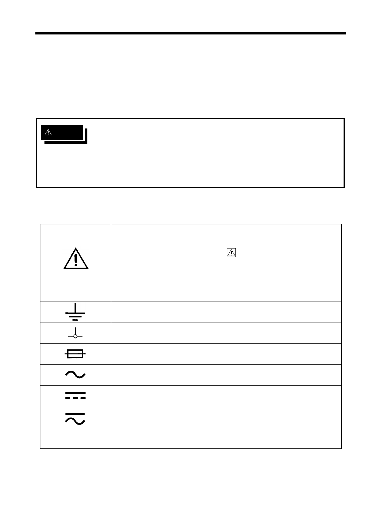
Safety symbols
・This symbol is affixed to locations on the equipment where the
operator should consult corresponding topics in this manual
(which are also marked with the
functions of the equipment.
・In the manual, this mark indicates explanations which it is
particularly important that the user read before using the
equipment.
Indicates a grounding terminal.
symbol) before using relevant
Indicates a grounding terminal for measurement.
Indicates a fuse.
Indicates AC (Alternating Current).
Indicates DC (Direct Current).
Indicates both DC (Direct Current) and AC (Alternating Current).
PEAK
────────────────────────────────────────────────────
Indicates a peak value.
Safety Notes
Page 16
iv
R
G
N
e
e
(
I
s.
I
I
I
────────────────────────────────────────────────────
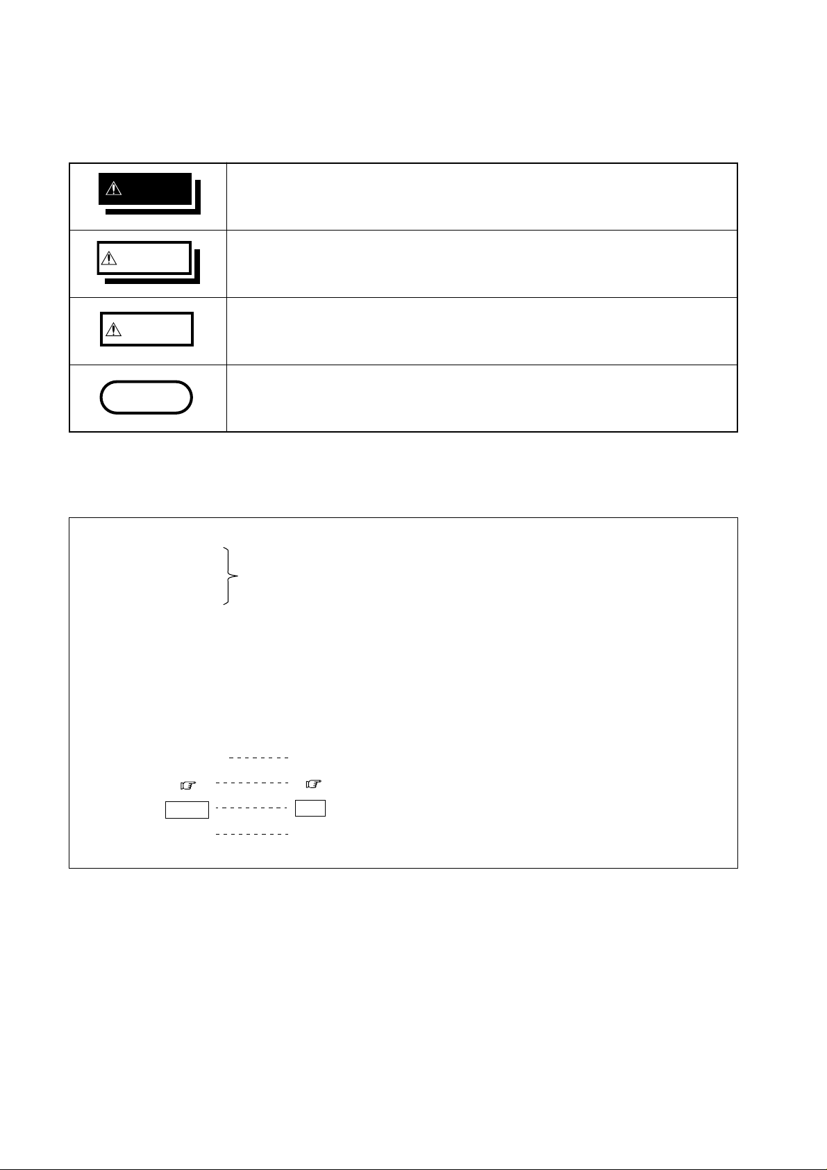
Conventions used in this manual
The following symbols are used in this Instruction Manual to indicate the
relative importance of cautions and warnings.
DANGE
WARNIN
CAUTIO
NOTE
Method
Operation
Indicates that incorrect operation presents extreme danger of
accident resulting in death or serious injury to the user.
Indicates that incorrect operation presents significant danger of
accident resulting in death or serious injury to the user.
Indicates that incorrect operation presents possibility of injury to the
user or damage to the equipment.
Denotes items of advice related to performance of the equipment or
to its correct operation.
Symbols used for setting and operating steps
Indicates a setting or operating procedure. Follow the numbered
sequence and perform the indicated steps.
Step
Referenc
Exampl
Bold character)
[]
Additional information about setting and operating procedures.
Indicate practical examples for setting and operating procedures.
Example
Set to FFT
( Section ..)
F1
[ FFT ]
ndicates display items or selection item
ndicates sections for reference.
ndicates operation keys.
ndicates function key displays.
────────────────────────────────────────────────────
Safety Notes
Page 17
v
G
R
N
────────────────────────────────────────────────────
otes on Use
In order to ensure safe operation and to obtain maximum performance from
the unit, observe the cautions listed below.
(1) Installation environment
WARNIN
DANGE
The unit should always be operated in a range from 5℃ to 40℃ and 35%
to 80% RH or less. Do not use the unit in direct sunlight, dusty
conditions, or in the presence of corrosive gases.
(2) Power supply connections
Before connecting the unit, make sure that the power supply voltage
matches the rated power supply voltage of the 8846 (
"Power Supply and Ground Connection".
Before connecting the unit to a battery or other DC source, make sure
that the intermediate switch is set to OFF. If the switch is ON, there is a
risk of sparks.
Section 4.2,
(3) Protective grounding
・Be sure to connect the ground terminal to a good ground ( Section 4.2,
"Power Supply and Ground Connection"). If the AC outlet is grounded, using
the supplied power cord with 3-prong plug will establish the ground
connection.
・Also when powering the unit from a battery or other DC source, connect the
ground terminal to a good ground.
(4) Before powering on
・Check that the power supply is correct for the rating of the unit. Also check
that the correct fuse is fitted. (
Connection". (The AC fuse is integrated in the unit.)
・The power switches of this unit are separate for AC power (power switch on
8846) and DC power (intermediate switch on DC power supply cable). If DC
power is being supplied and the intermediate switch is set to ON, the 8846
will operate also if the power switch is set to OFF.
────────────────────────────────────────────────────
Section 4.2, "Power Supply and Ground
Notes on Use
Page 18

vi
R
shock.
e
────────────────────────────────────────────────────
(5) Probe Connection, Measurement Voltage Input
DANGE
Maximum input ratings for the analog units 8916 - 8919, 8927, and 8928
and the input terminals of the 8846 are shown below. To avoid the risk
of electric shock and damage to the unit, take care not to exceed these
ratings.
The 8918 TEMPERATURE UNIT is designed specifically for
thermocouples. Do not use it with any other components. (Circuit
protection is provided for up to 100 V DC or AC, but any voltage above
this value will destroy the unit.)
The maximum floating voltage of 8916 to 8919, 8928 (voltage between
input and 8846 frame ground, and between inputs of other analog units)
is shown below. To avoid the risk of electric shock and damage to the
unit, take care that voltage between channels and between a channel
and ground does not exceed these ratings.
The maximum floating voltage rating applies also if an input attenuator
or similar is used.
The 8927 ANALOG UNIT is not isolated from the ground of the 8846
(common ground). To avoid the risk of electric shock and damage to the
unit, make sure that the ground connection and input connections are
correctly established. (
Section 4.4)
When measuring power line voltages with the 8916, 8917, or 8919,
always connect the probe to the secondary side of the circuit breaker.
Connection to the primary side involves the risk of electric shock and
damage to the unit.
Always use the supplied input cables (units 8916, 8917, and 8919 use
the input cable 9574, and unit 8927 uses the connecting cable 9437).
Any exposed metal sections in an input cable consist a risk of electric
Input/output terminalMaximum input rating Maximum floating voltag
8916 inputs
8917 inputs
500 V DC+AC peak 450 V AC/DC
8919 inputs
8918 inputs
8927 inputs
8928 inputs
100 V AC/DC 250 V AC/DC
50 V DC+AC peak No floating
10 V DC+AC peak 40 V DC+AC peak
EXT TRIG
START
STOP
-5 V to 10 V No floating
PRINT
EXT SMPL
MIC
TRIG OUT
NG
0 V to 5 V DC+AC peak No floating
-20 V to +30 V
500 mA max
200 mW max
No floating
────────────────────────────────────────────────────
Notes on Use
Page 19
vii
G
R
N
N
────────────────────────────────────────────────────
WARNIN
DANGE
CAUTIO
The logic units all have and the 8846 have a common ground.
(6) Replacing the fuse and input units
Use a DC power supply fuse of the proper rating (12 A/250 V).
In order to avoid accidents from electric shock, before removing or
replacing an input unit or changing a fuse, check that the input cables
are disconnected, turn off the power, and remove the power cable.
Normally keep all eight input units installed permanently. If a unit is not
fitted, it must be replaced by a blanking panel. If the unit is operated
with an input unit not in place it poses a shock hazard.
(7) Recording paper
・This unit uses a thermal printer. The recording paper supplied has
characteristics finely tuned for use with the printer.
Using recording paper of a different specification may not only result in
impaired printing quality, but even prevent the printer from operating. Always
use the HIOKI specified product.
・Insert the paper with correct orientation (
Paper").
Section 4.6, "Loading Recording
CAUTIO
NOTE
(8) Using a printer
Using the printer in a high-temperature or high-humidity environment should be
avoided at all costs. This can seriously reduce the printer life.
(9) Storing
When the unit is not to be used for an extended period, set the head up/down
lever to the "head up" position. This will protect the printer head and prevent
deformation of the rubber roller.
────────────────────────────────────────────────────
Notes on Use
Page 20

viii
N
────────────────────────────────────────────────────
(10) Shipping
CAUTIO
NOTE
NOTE
Remove the printer paper from the unit. If the paper is left in the unit, paper
support parts may be damaged due to vibrations.
Remove the tape from the unit.
If reshipping the unit, preferable use the original packing.
(11) Others
・ In the event of problems with operation, first refer to Section 23.4, "Trouble
shooting".
・ Carefully read and observe all precautions in this manual.
────────────────────────────────────────────────────
Notes on Use
Page 21

ix
C
────────────────────────────────────────────────────
hapter Summary
Chapter 1 Product Overview
Contains an overview of the unit and its features.
Chapter 2 Specifications
Contains general specifications and detailed function specifications.
Chapter 3 Logic Input Section and Analog Input Unit
Contains specifications and precautions for logic input section and input
amplifier units.
Chapter 4 Setup and Preparations
Explains how to set the unit up for measurement.
Chapter 5 Operation Steps for Basic Measurement
Explains how to operate the keys and JOG/SHUTTLE control for carrying out
basic measurement functions.
Chapter 6 Memory Recorder Function Settings
Explains how to use the memory recorder functions of the unit.
Chapter 7 Recorder Function Settings
Explains how to use the recorder functions of the unit.
Chapter 8 FFT Function Settings
Explains how to use the FFT analysis functions of the unit.
Chapter 9 Input Channel Settings
Explains how to make settings using the channel setting screen.
Chapter 10 Trigger Functions
Explains how to use the trigger functions of the unit.
Chapter 11 System Screen Settings
Explains how to make settings using the system setting screen.
Chapter 12 Printout of Waveform Data and Processing Data
Explains how to print out data and how to read printed charts.
Chapter 13 Storing Data On MO Disk
Explains how to store data on MO disk and how to read stored data.
────────────────────────────────────────────────────
Chapter Summary
Page 22

x
────────────────────────────────────────────────────
Chapter 14 Calculating Waveform Data
Explains the waveform processing functions of the unit and how to input
processing equations.
Chapter 15 Determining Waveform Parameters / Evaluating Parameter Values
Explains waveform parameter processing functions and waveform parameter
evaluation. 14 parameters of the input waveform are determined and used for
GO/NG evaluation.
Chapter 16 Waveform GO/NG Evaluation
Explains the waveform evaluation function which uses an evaluation area
created by the user for GO/NG evaluation.
Chapter 17 Memory Segmentation Function
Explains the memory segmentation function which splits the internal memory
into blocks for storing waveform data.
Chapter 18 Waveform Averaging
Explains the waveform averaging function which serves to remove noise
components from the waveform.
Chapter 19 Using the A/B Cursors / Waveform Scrolling
Explains how to use the A/B cursors and how to perform waveform scrolling.
Chapter 20 LEVEL MON. Key, CH.SET Key, HELP Key
Explains how to use the LEVEL MON., CH.SET, and HELP keys.
Chapter 21 External Input/Output Connectors / Key Lock Function
Gives specifications and usage details of the external input/output connectors.
Chapter 22 Using the D/A Output Unit 9539 (Option)
Gives specifications and usage details of the optional D/A output unit 9539.
Chapter 23 Maintenance
Describes maintenance and fuse replacement procedures.
Chapter 24 Error and Warning Messages
Describes error and warning messages and lists reference sections in the
manual.
Appendix Contains a glossary of terms used in this manual and gives some basic
reference information.
────────────────────────────────────────────────────
Chapter Summary
Page 23

1
1
w
1
────────────────────────────────────────────────────
Chapter
1
2
.1 Major Features
(1) Storage capability using MO disk
Waveform data and parameter information can be recorded on MO disk.
(2) Easy to read, large color display
The 9.5-inch TFT color screen with a resolution of 640 × 480 dots shows all
information at a glance.
(3) Built-in thermal printer for A4-size printouts
・The built-in printer delivers waveform printouts on the spot.
・The printer can also be used to print screen shots and parameter information.
Product Overvie
3
4
5
6
7
8
9
(4) 16-channel, 14-bit high-resolution recording capability
Using the analog unit 8927 (designed specifically for the 8845 and 8846, not
isolated from ground), waveform recording can be performed in up to 16
channels with 14-bit resolution.
(5) Expansion units designed for 8840 can be used
・The 8916 ANALOG UNIT, 8917 DC/RMS UNIT, 8918 TEMPERATURE UNIT,
and 8919 FFT UNIT can be used in the 8846.
・Units designed for 8840 are connected in a floating configuration (isolated
from ground).
(6) Playback of recorded waveform data
The optional 9539 D/A OUTPUT UNIT allows output of recorded waveform
data (2 channels) as an analog waveform with a +6.4 to -6.4 V range.
(7) Voice memo capability
Simply by connecting a microphone to the unit, the user can record a voice
memo along with waveform data.
10
11
12
13
14
A
────────────────────────────────────────────────────
1.1 Major Features
Page 24

2
────────────────────────────────────────────────────
(8) Simple function key interface
Thanks to its GUI-inspired design using large function key graphics, the unit
is easy to set up and operate.
(9) 3 incorporated functions
・Memory recorder with up to 200 kS/s and 2 M word capacity (using 1 unit/1
channel); X-Y plotting also possible.
・Continuous real-time recording capability to tape or paper in recorder function
・FFT function with 12 analysis patterns
(10) Trigger function
・Digital trigger circuit
・4 trigger types: level trigger, window-in trigger, window-out trigger, logic
trigger
(11) Waveform data processing
Absolute waveform values, integral values, and differential values can be
calculated, and arithmetic processing of multiple waveform data is also
possible.
(12) Waveform parameter calculation
14 waveform values including maximum, minimum, and effective values can
be determined.
(13) Waveform evaluation
A good/no-good decision (GO/NG) can be performed depending on whether the
waveform is in a standard area or not. The standard area can be easily set up
using the graphics editor.
(14) Scaling function
By setting the physical amount and the unit to be used for 1 V input, the
measurement result can be converted into any desired scale.
(15) Strain gauge adapter
The measurement with a strain gauge adapter is possible by using the 8928
STRAIN UNIT.
(16) GP-IB interface
The optional 9537 GP-IB INTERFACE applied to IEEE-488.2 can be used.
It is possible to input and output data and remotely control.
(17) SCSI interface
The optional 9538 SCSI INTERFACE applied to ANSI-X3.131-1986, JIS-X6051
can be used. The waveform data recorded on a MO disk can be transferred to
a personal computer with using the 9606 DATA CONVERSION UTILITY.
────────────────────────────────────────────────────
1.1 Major Features
Page 25

3
1
────────────────────────────────────────────────────
.2 Identification of Controls and Indicators
1
Controls and indicators of the unit are listed on the following pages, along
with a simple explanation of their function.
2
3
4
5
6
7
8
9
10
11
12
13
14
A
────────────────────────────────────────────────────
1.2 Identification of Controls and Indicators
Page 26
4
18171674123568
91011
1213191415
20
────────────────────────────────────────────────────
Front Panel
────────────────────────────────────────────────────
1.2 Identification of Controls and Indicators
Page 27
5
0
1
2
314151617181920
────────────────────────────────────────────────────
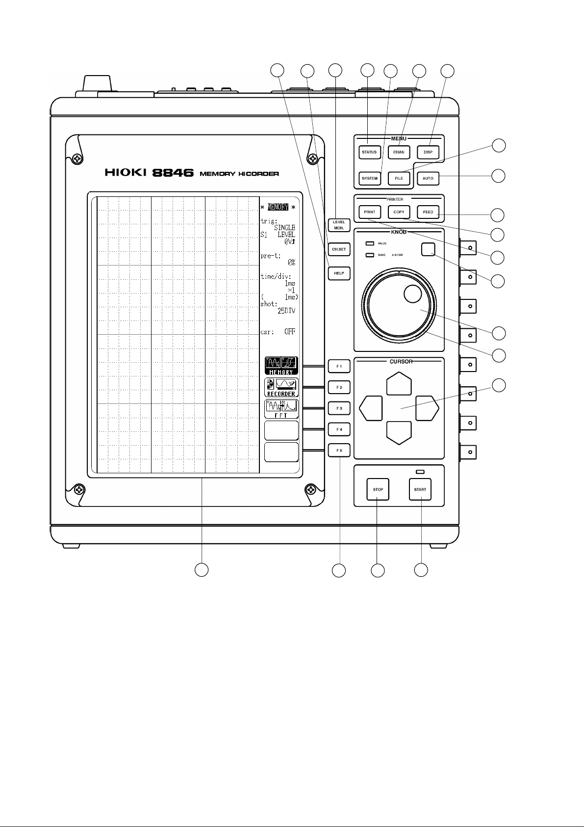
1
STATUS key Causes the display to show the STATUS screen which
serves for setting most measurement parameters.
2
CHAN key Causes the display to show the CHANNEL screen which
serves for making input channel settings.
3
DISP key Causes the display to show measurement and analysis
results.
1
2
4
SYSTEM key Causes the display to show the SYSTEM screen which
serves for making system-wide settings such as for the
scaling function (
5
FILE key Causes the display to show the MO screen which serves
for making MO disk settings (
6
AUTO key Pressing this key activates automatic setting of X and Y
axis range values for easy reading (
7
PRINT key Serves to print out stored waveforms ( Chapter 12).
8
COPY key Serves to print out a hard copy of the current screen
display (
9
FEED key Causes the printer paper to advance for as long as the
key is pressed (
1
Select key Selects the function that is controlled by the
JOG/SHUTTLE knob. With each push of the key, the
functions is toggled between VALUE and WAVE A B
CSR. The respective LED lights up (
1
JOG key Rotary control knob that serves to change values, move
the A/B cursors, and scroll the waveform.
Chapter 12).
Chapter 11).
Chapter 13).
Sections 6.3, 7.3).
Chapter 12).
Chapter 19).
3
4
5
6
7
8
9
1
SHUTTLE key Concentric ring that serves to move the flashing cursor,
A/B cursors, and to scroll the waveform. The speed of
movement is proportional to the rotation angle
(
Chapter 19).
1
CURSOR keys These keys serve to move the flashing cursor in the four
directions.
START key Initiates the measurement and analysis. During
measurement, the LED above the key is lit.
STOP key Stops measurement and analysis.
LEVEL MON. key Serves to check the input signal level ( Chapter 20).
CH. SET key Serves to display and change measurement parameters
for the various channels (
HELP key Serves to indicate the position of the currently displayed
screen information in relation to the entire recording
length (
F1 - F5 keys Serve to select setting items.
LCD screen
Chapter 20).
Chapter 20).
10
11
12
13
14
A
────────────────────────────────────────────────────
1.2 Identification of Controls and Indicators
Page 28
6
21
212223262728313325292432
30
────────────────────────────────────────────────────
Left Side View
Right Side View
────────────────────────────────────────────────────
1.2 Identification of Controls and Indicators
Page 29

7
1222324
5
62728
9
0313233
────────────────────────────────────────────────────
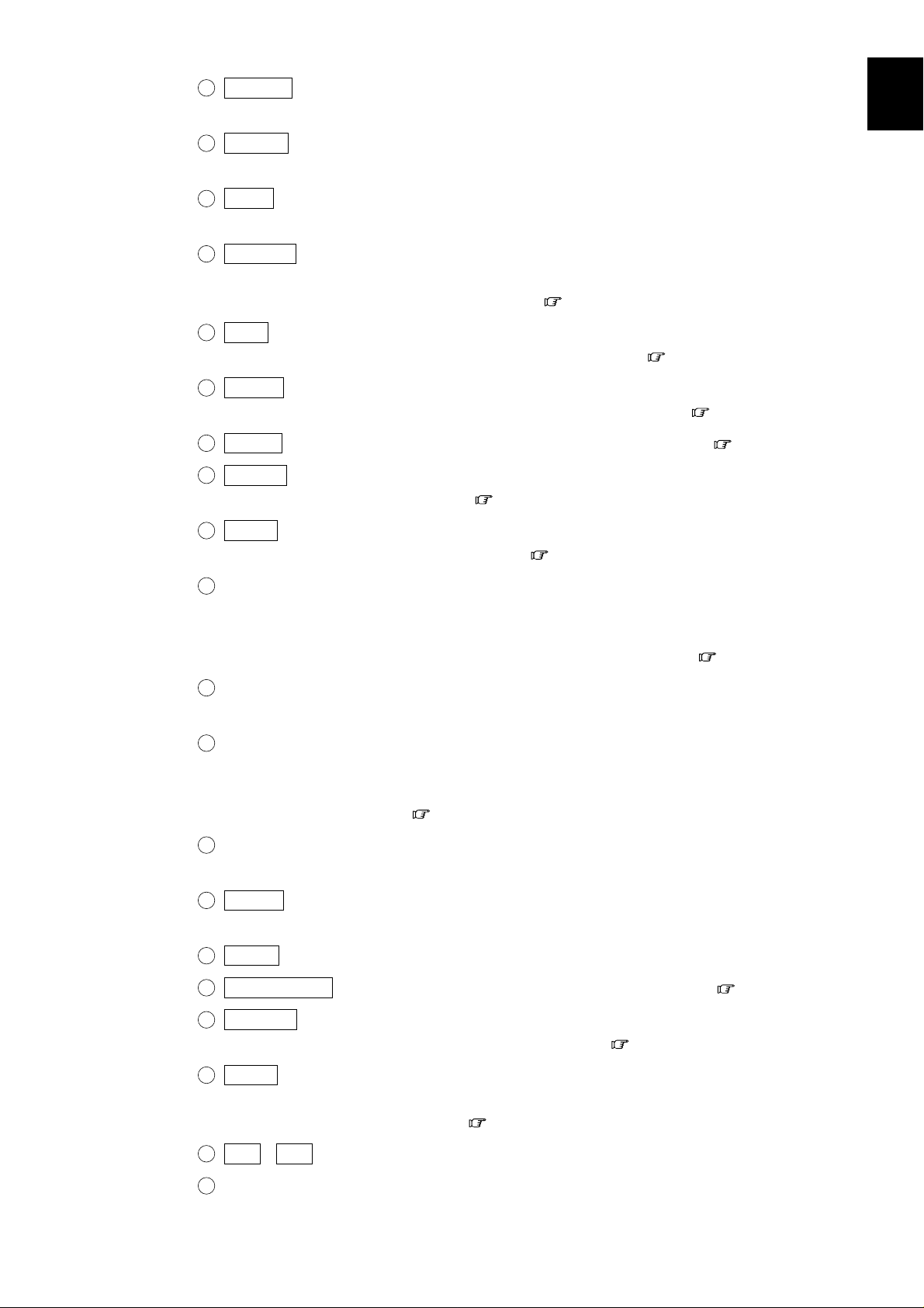
2
Printer
AC POWER switch Serves to turn the unit on and off.
1
Protective ground terminal (GND)
AC connector The supplied power cord must be plugged in here.
2
Input unit slots These slots accept various input units, such as
the 8916
8918
8927
2
Analog input connector (on 8927 ANALOG UNIT) Unbalanced analog input
Ventilation slots
Fastening screw Secures the plug-in unit.
2
Expansion slot Accepts the optional unit.
The 9537 GP-IB INTERFACE, 9538 SCSI INTERFACE,
and 9539 D/A OUTPUT UNIT can be used.
3
Analog output connector (of the 9539 D/A OUTPUT UNIT)
BUSY lamp MO drive activity indicator. Indicates during drive
operation.
Disk insertion slot The MO disk is inserted here.
ANALOG UNIT, 8917 DC/RMS UNIT,
TEMPERATURE UNIT, 8919 FFT ANALOG UNIT,
ANALOG UNIT, and 8928 STRAIN UNIT.
2
3
4
5
6
7
Tilt support Serves to tilt the unit upwards.
8
9
10
11
12
13
────────────────────────────────────────────────────
1.2 Identification of Controls and Indicators
14
A
Page 30
8
3538373641424044343943
45
────────────────────────────────────────────────────
Top View
Bottom View
────────────────────────────────────────────────────
1.2 Identification of Controls and Indicators
Page 31

9
435363738394041
2
3
4
5
────────────────────────────────────────────────────
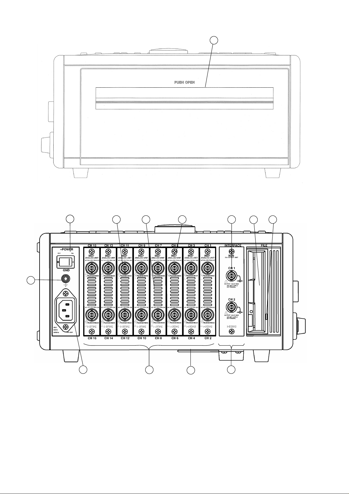
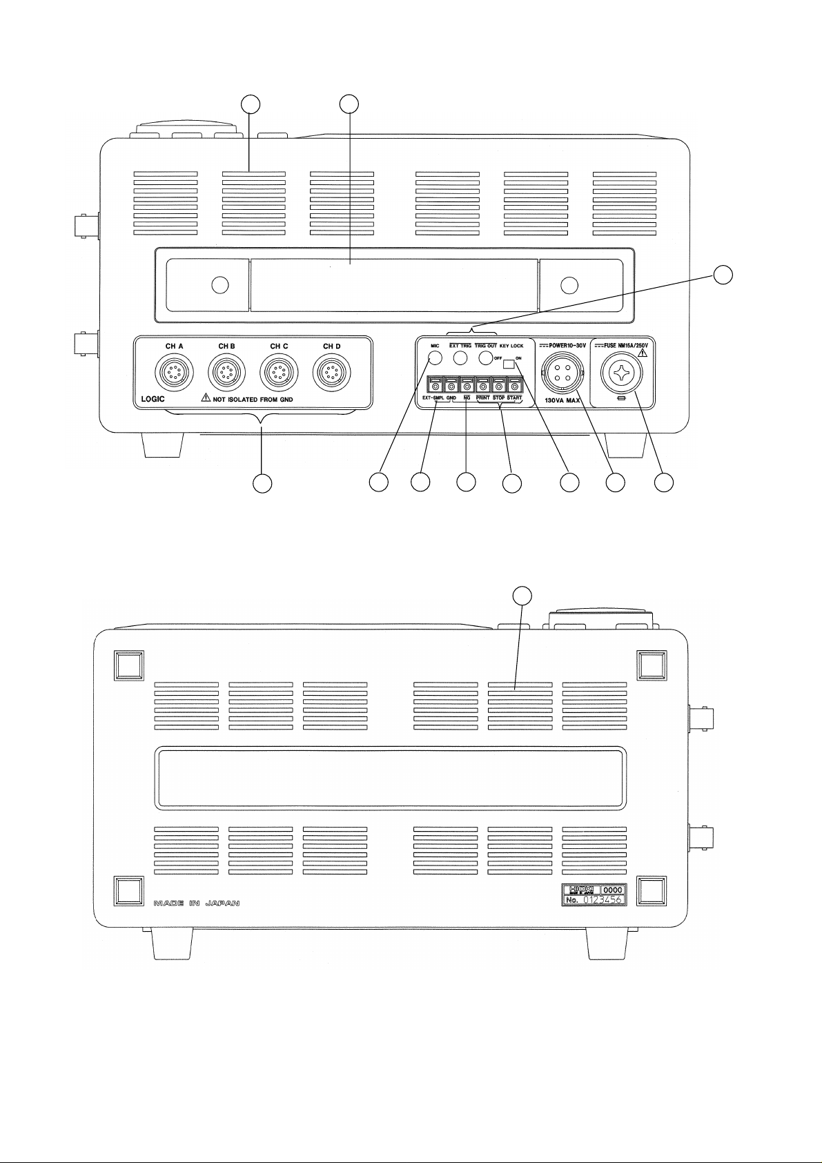
3
Ventilation slots
Handle Serves for transporting the 8846.
Logic probe connectors Input connector for the logic input section, designed for
the dedicate logic probes (CH A, CH B, CH C, CH D)
(
Chapter 3).
MIC (microphone) For connection of a microphone (
Chapter 21).
connector
Trigger connectors Can be used to synchronize multiple units, using the
EXT TRIG input and TRIG OUT output
(
Chapter 21).
KEY LOCK switch When this switch is set to ON, all keys of the 8846 are
inactive. The key lock condition is maintained also when
the power is switched off and on again (
Chapter 21).
Remote terminals Start, stop, and print operation can be controlled via
external signals (
Chapter 21).
NG evaluation output When the waveform evaluation based on waveform
terminal parameters has resulted in NG, a signal is output from
this terminal (
4
External sampling Allows input of an external sampling signal
terminal (
4
DC power supply Allows use of an external DC source to power the unit
Chapter 21).
Chapter 21).
connector (with dedicated DC cable).
4
Fuse holder Contains a DC power supply fuse.
4
Ventilation slots
────────────────────────────────────────────────────
1.2 Identification of Controls and Indicators
Page 32

10
────────────────────────────────────────────────────
────────────────────────────────────────────────────
1.2 Identification of Controls and Indicators
Page 33

11
Basic specifications
2
s
2
────────────────────────────────────────────────────
Chapter
1
2
.1 General Specifications
■
Number of units
(maximum)
Memory capacity
When 1 unit is in use
When 2 units are in use
When 4 units are in use
When 8 units are in use
Maximum sampling speed
Specification
Analog 8 units
8 channels when using with only the 8916, 8917, 8918, 8919, 8928
16 channels when using with only the 8927
(The logic channels are standard equipment for the 8846, common
ground with main unit)
2 M words
8916, 8917, 8918, 8919, 8928 8927
12 bits×2 M words /channel 14 bits×1 M words /channel
12 bits×1 M words /channel 14 bits×500 K words /channel
12 bits×500 K words /channel 14 bits×200 K words /channel
12 bits×200 K words /channel 14 bits×100 K words /channel
one unit of the 8928 equals two units of the 8916 to 8919
Memory recorder, FFT 200 kS/s (8927 is not in use)
100 kS/s (8927 is in use)
Recorder 80 kS/s
3
4
5
6
7
8
9
10
Input method
Time measurement
functions
Time measurement
precision (maximum)
Backup battery and
lifetime
Operational ranges for
temperature and humidity
Temperature and humidity
ranges for assured
accuracy
Temperature and humidity
ranges for storage
────────────────────────────────────────────────────
Plug-in analog input units
floating input 8916, 8917, 8918, 8919, 8928
no floating 8927
Auto calendar with automatic leap year, 24 hour clock
20 ppm (25℃)
Used for clock and to preserve settings, 8 years (reference value at
25℃)
Temperature: 5℃ to 40℃
Relative humidity: 35% to 80% RH (with no condensation)
Temperature: 23℃±5℃
Relative humidity: 35% to 80% RH (with no condensation)
Temperature: -10℃±50℃
Relative humidity: 35% to 80% RH (with no condensation)
2.1 General Specifications
11
12
13
14
A
Page 34

12
Display
────────────────────────────────────────────────────
Insulation resistance and
dielectric strength
Power supply
Fuse
Maximum rated power
Dimensions
Mass
At least 10 MΩ/500 VDC, one minute at 1.5 kVAC
(between the frame and the AC power supply)
At least 10 MΩ/500 VDC, one minute at 700 VDC
(between the frame and the DC power supply)
At least 100 MΩ/500 VDC, one minute at 2 kVAC
(between the input units (excluding 8918, 8927, 8928) and the frame)
At least 100 MΩ/500 VDC, one minute at 1.5 kVAC
(between the input unit (8918) and the frame)
At least 100 MΩ/500 VDC, one minute at 500 VAC
(between the input unit (8928) and the frame)
At least 100 MΩ/500 VDC, one minute at 2 kVAC
(between the input units (excluding 8918, 8927, 8928))
At least 100 MΩ/500 VDC, one minute at 500 VAC
(between the input units (8928))
90 to 250 VAC (50/60 Hz)
10 to 30 VDC
10 to 30 VDC class A melting fuse (NM) 12 A/250 V
6.4 dia.×31.8 mm (DC power supply)
AC: 350 VA (when printer off, 130 VA)
DC: 130 VA (when printer off, 70 VA)
Approx. 280 (W)×306 (H)×140 (D) mm (excluding projections)
Approx. 7 kg
■
Screen
Display resolution
Dots spacing
Maximum display defect
ratio
■ Recorder
Method of recording
Recording paper
Width of recording
Recording speed
Paper feed accuracy
9.5 inch LCD display (TFT color LCD, 640×480 dots)
Waveform: 20 DIV f.s. × 15 DIV f.s.
Text: 60 characters × 40 characters
(1 DIV= 32 dots (vertically) × 32 dots (horizontally)
0.30 mm × 0.30 mm
Always-on dots + always-off dots = max. 15
Thermosensitive recording method using a thermal line head
Roll type thermosensitive recording paper, 216 mm × 30 m (long)
Total recording width: 212 mm±1mm (1696 dots)
Waveform portion: 200 mm±1mm f.s. (1 DIV=10 mm)
Approx. 25 mm/s max
±1% (25℃, 60% RH)
────────────────────────────────────────────────────
2.1 General Specifications
Page 35

13
────────────────────────────────────────────────────
■ External data storage
Device
Capacity
Data format
Recorded data
■ External input /output terminals
START
STOP
PRINT
EXT TRIG
EXT SMPL
Input signal active LOW
HIGH level 2.5 to 5.0 V LOW level 0 to 1.0 V
Pulse width HIGH level 20 ms at least LOW level 10 ms at least
Maximum allowable input -5 to 10 V
Input signal active LOW
HIGH level 2.5 to 5.0 V LOW level 0 to 1.0 V
Pulse width LOW level 5 μs at least
Maximum allowable input -5 to 10 V
Input terminal mini-jack connector, 3.5 mm diameter
Input signal active LOW
HIGH level 2.5 to 5.0 V LOW level 0 to 1.0 V
Pulse width LOW level 1 μs at least
Frequency 180 kHz max (90 kHz max when using the 8927)
Maximum allowable input -5 to 10 V
3.5-inch MO drive
640 MB (540, 230, 128 MB)
Accordance with ISO standard , overwrite object supported
Binary format and text format of the waveform data (memory
recorder, recorder, FFT), settings, waveform decision area, screen copy
(BMP file)
1
2
3
4
5
6
7
8
MIC
TRIG OUT
NG
Maximum allowable input 0 to 5.0 V DC+AC peak
Input terminal mini-jack connector, 3.5 mm diameter
Output signal active LOW
HIGH level 4.5 to 5.0 V LOW level 0 to 0.5 V
Pulse width LOW level 1.5±0.5 ms
Maximum allowable input -20 to 30 V, 500 mA max, 200 mW max
Output terminal mini-jack connector, 3.5 mm diameter
Output signal active LOW
HIGH level 4.5 to 5.0 V LOW level 0 to 0.5 V
Pulse width HIGH level 20 ms at least LOW level 70 ms approx.
Maximum allowable input -20 to 30 V, 500 mA max, 200 mW max
9
10
11
12
13
14
────────────────────────────────────────────────────
2.1 General Specifications
A
Page 36

14
y
2
────────────────────────────────────────────────────
.2 Trigger Unit Specifications
Trigger Method
Trigger modes
Trigger source
Analog trigger
Logic trigger
Digital comparison
Memory recorder, FFT Single, repeat, auto, auto-stop
functions
Recorder function Single repeat
CH1 - CH16 Analog waveform to input for each channel
CHA - CHD Logic waveform to input for each channel
External trigger Input signal to EXT TRIG terminal
Timer trigger Start, stop, interval selectable
Sources can be set on or off. When all sources are off, the unit is in
the free-run state.
Trigger conditions can be set for each source individually.
Uses analog input waveform (channel 1 - 16) as trigger source.
Level trigger Trigger level is set as voltage. Triggering occurs
when the signal passes the trigger level with the
selected slope (rising edge, falling edge).
Window-in trigger Upper and lower trigger levels can be set.
Triggering occurs when the waveform enters the
defined area.
Window-out trigger Upper and lower trigger levels can be set.
Triggering occurs when the waveform leaves the
defined area.
Uses the logic input waveform (CH A - CH D) as trigger source.
Triggering occurs when the set pattern is matched.
Trigger source AND, OR
Trigger filter
Trigger level resolution
Pre-trigger
Trigger output
AND, OR logic can be used to link trigger sources.
AND Triggering occurs when all sources have been triggered.
OR Triggering occurs when one trigger source has been
triggered.
Trigger width can be set by number of sampling points.
OFF, 10, 20, 50, 100, 150, 200, 250, 500, 1000
0.25 % f.s. (f.s. = 20 DIV)
0, 2, 5, 10, 20, 30, 40, 50, 60, 70, 80, 90, 95, 100, -95 % (in the memor
recorder function,) unsettable at external sampling
Signal is output from TRIG OUT terminal when triggering occurs.
────────────────────────────────────────────────────
2.2 Trigger Unit Specifications
Page 37

15
2
────────────────────────────────────────────────────
.3 Memory Recorder Function Specifications
Time axis
500 μs/DIV (not available when 8927 is used)
1, 1.25, 2, 2.5, 5, 10, 20, 50, 100, 200, 500 ms/DIV
1, 2, 5, 10, 20 s/DIV
1, 2, 5 min/DIV
1
2
3
Time axis resolution
Time axis precision
Sampling period
Recording length
Display format
Recording line display
Interpolation function
Waveform magnification/
compression
Variable display function
Automatic store function
100 points/DIV (time axis magnification × 1)
±0.001% (relative scale vs. time error)
1/100 of the time axis
, 2000
(*2)
25, 50, 100, 200, 500, 1000
*1: when 16 channels are in use
*2: when 8 channels are in use
*3: when 4 channels are in use
*4: when 2 channels are in use
*5: when 1 channel is in use (when using the 8927, not selectable)
Single, dual, quad, oct screen display, X-Y single, X-Y dual display
16-color (LCD)
dark, medium dark, normal, light (printer)
dot (no interpolation), line (linear interpolation)
Time axis ×10, ×5, ×2, ×1, ×1/2, ×1/5, ×1/10, ×1/20, ×1/50,
×1/100, ×1/200, ×1/500, ×1/1000
Voltage axis ×20, ×10, ×5, ×2, ×1, ×1/2, ×1/5, ×1/10
Settable upper and lower limit (-9.9999E+29 to 9.9999E+29)
0 V (position) fixed; magnification/compression from
0.0001E-29V/DIV to 9.9999E+28V/DIV
ON/OFF switchable. Automatic recording of waveform data on MO
disk after completion of measurement.
(*1)
, 5000
(*3)
, 10000
(*4)
, 20000
(*5)
DIV
4
5
6
7
8
9
Auto-print
Manual print
Partial print
Print smoothing function
Logging function
Memory segmentation
function
Superimposition function
Waveform scrolling
ON/OFF switchable. Automatically prints the memorized waveform
Prints by pressing the PRINT key
Prints between the A and the B cursors
ON/OFF switchable. Doubles density along time axis for smooth
printout (at lower speed).
Numeric printout of waveform data
Memory area of each channel can be divided into max. 63 blocks.
Multi-block memory (memory segmentation)
Sequential save
ON/OFF switchable
Available in both the left/right and the up/down directions
10
11
12
13
14
A
────────────────────────────────────────────────────
2.3 Memory Recorder Function Specifications
Page 38

16
2
────────────────────────────────────────────────────
.4 Recorder Function Specifications
(*5)
(*4)
(*3)
Time axis
(*1)
1.25, 2,
1, 2, 5, 10, 20 s/DIV
1, 2, 5, 10, 20 min/DIV
1 h/DIV
*1: when 1 channel is in use
*2: when 2 channels are in use
*3: when 4 channels are in use
*4: when 8 channels are in use
*5: when 16 channels are in use
(*2)
2.5,
5,
20, 50, 100, 200, 500 ms/DIV
10,
Time axis resolution
Time axis precision
Recording time
Display format
Recording line display
Interpolation function
Waveform magnification/
compression
Variable display function
Data storage medium
Data transferring
100 points/DIV (time axis magnification × 1)
±0.001% (relative scale vs. time error)
Continuous or settable from 1 second to 366 days 23 h 59 min 59 s in
1-second intervals
Single, dual, quad, oct screen display
16-color (LCD)
dark, medium dark, normal, light (printer)
dot (no interpolation), line (linear interpolation) line only when
measurement
Time axis ×10, ×5, ×2, ×1, ×1/2, ×1/5, ×1/10, ×1/20, ×1/50,
×1/100, ×1/200, ×1/400, ×1/500, ×1/800, ×1/1000,
×1/2000, ×1/5000, ×1/10000, ×1/20000, ×1/50000,
×1/100000
Voltage axis ×20, ×10, ×5, ×2, ×1, ×1/2, ×1/5, ×1/10
Settable upper and lower limit (-9.9999E+29 to 9.9999E+29)
0 V (position) fixed; magnification/compression from
0.0001E-29 V/DIV to 9.9999E+28 V/DIV
OFF, printer, MO
Transfer the recorded data in memory recorder function to memory
recorder function.
Manual printing
Partial print
Waveform scrolling
Logging function
────────────────────────────────────────────────────
2.4 Recorder Function Specifications
Activated by pressing the PRINT key
Printout of data in memory at completion of recording
Printout of all recording data when data are read
Prints between the A and the B cursors
Available in both the left/right and the up/down directions
Numeric printout of waveform data
Page 39

17
s
2
────────────────────────────────────────────────────
.5 FFT Function Specifications
FFT range setting
Frequency resolution
133, 333, 667 mHz
2, 4, 8, 20, 40, 80, 200, 400, 800 Hz
2, 4, 8, 16, 20, 32, 40, 80* kHz (*:not available when 8927 is used)
1/400
1
2
3
Number of sampling point
Dynamic range
Antialiasing filter
Window functions
FFT analysis modes
X-axis setting
Y-axis setting
FFT channel mode
Analysis channels
Reference data
Display format
Recording line display
1000 (storage waveform)
72 dB (logical value for 8916, 8917, 8918, 8919, 8928)
84 dB (logical value for 8927)
ON/OFF switchable. Automatic cutoff frequency selection linked to
frequency range (for channels using 8919 FFT unit)
Rectangular, Hanning, Exponential
Storage waveform, linear spectrum, RMS spectrum, power spectrum,
auto-correlation function, histogram, transfer function, cross-power
spectrum, cross-correlation function, unit-impulse response, coherence
function, octave analysis
Time, frequency (linear, logarithmic), real-number voltage (Nyquist
only)
Voltage (real-number, imaginary number, absolute value, logarithmic)
1 channel FFT, 2 channel FFT
2 channels selectable from all analog channels
Newly read waveform, waveform stored with memory recorder
function
Single, dual screen display, Nyquist display
Identical fixed color for g1, g2 (display), Dark (printer)
4
5
6
7
8
9
Interpolation function
Waveform magnification/
compression
Automatic store function
Auto-print
Manual print
Logging function
dot (no interpolation), line (linear interpolation)
Selectable upper and lower limit (only voltage values set with
STATUS screen; settings made with CHANNEL screen are valid only
for histogram of X-axis)
ON/OFF switchable. Automatic recording of waveform data on MO
disk after completion of measurement.
ON/OFF switchable. Automatically prints the memorized waveform
Prints by pressing the PRINT key
Numeric printout of waveform data
10
11
12
13
14
A
────────────────────────────────────────────────────
2.5 FFT Function Specifications
Page 40

18
2
────────────────────────────────────────────────────
.6 Auxiliary Functions Specifications
■ Averaging function
Memory recorder
FFT
Averaging count (OFF, 2 - 256, summing averaging up to specified
count, then exponent averaging)
Averaging count (OFF, 2 - 4096)
Selectable functions: summing averaging, exponent averaging (each on
time axis or frequency axis), peak hold (frequency axis)
■ Waveform decision function
Waveform area evaluation
Decision modes
Stop modes
Decision time
Decision period
Comparison to reference area
Memory recorder (single, X-Y single display)
FFT (single, Nyquist display)
Out NG (fail) if any part of the waveform goes out of the decision
All out NG (fail) if the waveform is entirely outside the decision
Go stop, NGstop, GO&NG stop
On stop, printer output and waveform save can be selected.
20 ms approx.
1.75 s approx. (1 ch, 1 mS/DIV, 25 DIV, ×1, line display during
compressed display or when the recoding length is long, this becomes
slower.
area.
area.
Reference area editor
Editor commands
Waveform parameter
evaluation
(memory recorder, recorder)
Evaluation modes
Evaluation output
Graphic editor
Line (dotted line), Paint, Read Waveform, Erase, Parallel Move (with
overwrite), Reverse, Clear (partial deletion), All Clear (screen
deletion), Undo, Save
Upper and lower trigger limits for waveform parameter processing can
be set
Out NG when parameter leaves specified range
In NG when parameter enters specified range
Signal is output from NG terminal when NG occurs.
────────────────────────────────────────────────────
2.6 Auxiliary Functions Specifications
Page 41

19
t
────────────────────────────────────────────────────
■ Calculation processing
Waveform processing
(Memory recorder)
Waveform parameter
(Memory recorder, recorder)
■ Other function
(1) System screen
Start condition backup
Grid settings
Channel marker
List/gauge print function
Arithmetic calculation, absolute value, exponent, common logarithm,
square root, displacement average, 1st and 2nd differential, 1st and
2nd integral, parallel displacement on time axis, trigonometric
functions (sin, cos, tan), reverse trigonometric functions (asin, acos,
atan)
Average value, effective value, peak-to-peak value, maximum value,
time to maximum value, minimum value, time to minimum value,
period, frequency, rise time, fall time, area, standard deviation, area
value, XY area value,
ON/OFF switchable. (Retains measurement status.)
OFF, standard, fine, standard (dark), fine (dark), standard (shaded),
fine (shaded) (only OFF and standard for display)
ON/OFF switchable. Waveform numbered with channel number.
Always used (regardless of ON/OFF setting) for logic waveforms. Not
valid for FFT.
ON/OFF switchable. Together with measurement waveform,
measurement settings (list) and Y-axis scale (gauge) information is
printed.
LCD backlight saver
function
Comment input function
Scaling function
Subsampling print function
(2) Key operation
A4 print function
Display copy function
List print function
Auto-range function
Level monitor function
ON/OFF switchable. Turns LCD backlight off automatically after 10
minutes of key inactivity.
Input and printout of comments possible.
ON/OFF switchable. Converts voltage values into any unit. Can be se
separately for each channel.
ON/OFF switchable. Omits interpolation in envelope display.
Activated by pressing FEED key and COPY key simultaneously.
Displayed waveform is printed out in A4 size.
Activated by pressing COPY key. Produces a hard copy of display
contents.
Activated by pressing PRINT key when display shows setting
information. Produces a list of parameter settings.
Activated by pressing AUTO key (not valid in FFT mode). Selects
optimum time axis and voltage axis for input waveform.
Activated by pressing LEVEL MON. key. Serves to verify voltage
range position for input waveform in each channel.
Help function
────────────────────────────────────────────────────
Activated by pressing HELP key. Shows relative position of
displayed data within entire recorded data. When voltage axis is
enlarged, relative position of displayed data to full-scale point for each
channel is shown (memory recorder, recorder).
When memory segmentation is used, usage condition of each block is
shown (memory recorder).
2.6 Auxiliary Functions Specifications
Page 42

20
────────────────────────────────────────────────────
(3) External terminal and switches
Remote control
External sampling
Voice memo function
Key lock
(4) Others
Comment printing
Cursor measurement
function
Measurement start, stop, and print control via rear- panel connectors.
Signal input to EXT SMPL connector (max. 180 kHz) can be used for
sampling (limited by number of recording channels and input units).
Microphone connected to MIC connector can be used to record a voice
memo for any unit.
ON/OFF switchable
Function, channel, input range, 0 V position, trigger time, DIV and
other information can be printed.
Time, potential, temperature, frequency difference between A and B
cursor can be measured.
Potential, time from trigger, frequency at A or B cursor can be
measured.
────────────────────────────────────────────────────
2.6 Auxiliary Functions Specifications
Page 43

21
2
────────────────────────────────────────────────────
.7 Accessories and Options
Accessories
Power cord 1
Cord for DC power supply 1
Recording paper (roll) 1
Recording paper attachment 2
Instruction Manual 1
Protect cover 1
Spare fuse 1 (DC power supply 10 to 30 V: class A melting
fuse (NM) , 12 A/250 V, 6.4 dia. ×31.8 mm)
MO disk (230 MB) 1
Eject pin 1
Options
8916 ANALOG UNIT
8917 DC/RMS UNIT
8918 TEMPERATURE UNIT
8919 FFT ANALOG UNIT
8927 ANALOG UNIT (2 channel/one unit)
8928 STRAIN UNIT
9537 GP-IB INTERFACE
9538 SCSI INTERFACE
9539 D/A OUTPUT UNIT (for output of data recorded with recorder function)
9606 DATA CONVERSION UTILITY
Optional accessories
9231 RECORDING PAPER (6 rolls)
9303 PT
9305 TRIGGER CORD
9306 LOGIC PROBE
9307 LINE LOGIC PROBE
9308 LINE DIP DETECTOR??
9369 CARRYING CASE
9370 CARRYING CASE
220H PAPER WINDER
────────────────────────────────────────────────────
2.7 Accessories and Options
Page 44

22
it
Pre-
amplifier
Pre-
amplifier
)
Pre-
r
amplifier
Block Diagram
2
────────────────────────────────────────────────────
.8 System Operation
System operation is explained according to the block diagram.
(1) All system operations are controlled by a 32-bit CPU.
(2) The input units 8916, 8917, 8918, and 8919 incorporate high-speed 12-bit A/D
converters which are connected to the main unit via a photocoupler integrated
in each input unit. Each channel has its own power supply, to assure electrical
isolation from the main unit.
(3) The analog unit 8927 incorporates a 14-bit A/D converter and uses a common
ground with the main unit.
(4) The input signals for each channel are converted into digital form by the A/D
converter, and the resulting data are stored in the memory by the memory
control circuit.
(5) Measurement data stored in memory are processed by the CPU and displayed
on the LCD screen. The waveform displayed on the screen can be printed out.
(6) Waveforms can be recorded on MO disk and redisplayed using the D/A output
unit (option).
Analog input unit
8927 (1 unit 2 channels)
A/D
A/D
8916 to 8919, 8928
Logic input
(4 probes, corresponding to 1 unit)
Logic
probe
Logic
probe
A/D
Photo
couple
Memory
control and
trigger
circuit
Stored
memory
(2 M words
Main un
32 bit CPU
LCD display
Printer
Control
MO drive
Option
Logic
probe
Logic
probe
────────────────────────────────────────────────────
2.8 System Operation
9537
9538
9539
Page 45

23
G
t
8846 main unit
it
d
s
g
3
ts
3
────────────────────────────────────────────────────
Chapter
1
2
.1 Logic Inputs
・The logic input is located on the top side of the unit. Up to four probes can be
connected.
・Since one logic probe can record 4 channels, the combined maximum recording
capability for logic waveforms is 16 channels.
WARNIN
The 8846 has separate inputs for four probes, but the ground lines of
these inputs are not isolated from each other and from the frame ground
of the unit (common ground).
Do not connect logic probes other than supplied by HIOKI to the logic
inputs.
Logic and Analog Inpu
3
4
5
6
7
8
9
NOTE
Logic inpu
GND
Logic input un
Common groun
Logic
probe
Not floatin
If no logic probe is connected, the corresponding logic waveform is displayed
on the screen ad high level.
10
11
12
13
14
A
────────────────────────────────────────────────────
3.1 Logic Inputs
Page 46

24
3
R
R
R
────────────────────────────────────────────────────
.1.1 Logic Probes
NOTE
DANGE
Carefully read the documentation supplied with the probe.
■
9306 LOGIC PROBE
Input can be switched between voltage input and contact input. Suitable for a
wide range of applications, from checking electronic circuits to measuring
relay timing.
The 8846 has separate inputs for four probes, but the ground lines of
these inputs are not isolated from each other and from the frame ground
of the unit (common ground). If voltages with different ground levels are
input, probe short-circuiting may occur and lead to accidents.
■
9307 LINE LOGIC PROBE
・Can be used to detect the on/off status of AC line voltage. Maximum input
voltage is 250 V. The probe is suitable for timing measurements of relay
sequencers or similar.
DANGE
DANGE
・The probe provides internal isolation between channels and between input and
output.
The maximum floating (insulation) voltage between channels and between
input and output is 250 V AC. To avoid the risk of electric shock and
damage to the unit, make sure that the voltage in each channel and
between input and output does not exceed this value.
■
9308 LINE DIP DETECTOR
・Serves to detect momentary voltage drops in commercial power supply lines
(100, 120 V AC).
・Dip level switchable between 80% and 90%.
・Requires 8916 ANALOG UNIT, 8917 DC/RMS UNIT or 8919 FFT UNIT .
The banana plug on the LOW side (black) is directly connected to the
input clip (black). Take suitable precautions against the risk of electric
shock.
────────────────────────────────────────────────────
3.1 Logic Inputs
Page 47

25
3
3
────────────────────────────────────────────────────
.2 8916 ANALOG UNIT
1
・The 8916 is the analog unit for the 8840 and 8846 MEMORY HiCORDER.
・Follow carefully the advice of Section 3.2.2, "Safety Requirements."
.2.1 Specifications
Accuracy at 23℃±5℃, after 1 hour warming-up time
Accuracy guaranteed for six months.
Measurement ranges
DC amplitude accuracy
Zero position accuracy
Temperature characteristic
Frequency characteristic
Noise
Common mode rejection
ratio
Low-pass filter
5, 10, 20, 50, 100, 200, 500 mV/DIV
1, 2, 5, 10, 20 V/DIV
±0.25% f.s.
±0.1% f.s.(after zero adjustment)
Gain: ±0.02%f.s./℃
Zero position: ±0.015%f.s./℃
DC to 100 kHz, -3 dB
180 μVp-p (typical) maximum sensitivity range, with input shorted
100 dB minimum (at 50/60 Hz and with signal source resistance
100 Ω maximum)
Cutoff frequency 5, 50, 500 Hz, 5 kHz approx.
Can be turned on and off
2
3
4
5
6
7
8
Input type
Input resistance and
capacitance
A/D resolution
Maximum sampling speed
Input terminals
Maximum allowable input
voltage
Maximum floating voltage
Dimensions and mass
Accessories
Unbalanced (floating)
1MΩ±1% (at power supply off, 500 kΩ)
approx. 20 pF (at 100 kHz)
12 bits
200 kS/s
2 terminals (for banana plugs)
500 V (DC+AC peak)
450 V AC/DC (between input unit and frame, and between input
units)
110 (W) × 20 (H) × 88 (D) mm (excluding projections), 110 g approx.
9574 INPUT CABLE (1)
9
10
11
12
13
14
A
────────────────────────────────────────────────────
3.2 8916 ANALOG UNIT
Page 48

26
3
R
r
G
N
t
8846 main unit
x
x
────────────────────────────────────────────────────
.2.2 Safety Requirements
DANGE
WARNIN
CAUTIO
The maximum floating voltage (voltage between 8916 input and 8846
frame, and between inputs of other analog units) is 450 V AC/DC. To
avoid the risk of electric shock and damage to the unit, take care that
voltage between 8916 input and 8846 frame, and between inputs of othe
analog units does not exceed these ratings.
The maximum allowable input to the 8916 is 500 V (DC+AC peak). To
avoid the danger of electric shock or damage to the equipment, ensure
that the applied voltage never exceeds this level.
The maximum floating voltage rating applies also if an input attenuator
or similar is used.
When measuring voltages in power lines with high current capability,
always connect the probe to the secondary side of the circuit breaker, to
avoid the risk of electric shock and damage to the unit.
・For safety reasons, only use the 9574 INPUT CABLE provided with the unit
for measurement.
・Before using the unit, make sure that the sheathing on the input cables is no
damaged and that no bare wire is exposed. If there is damage, using the
unit could cause electric shock. Replace with the specified 9574 INPUT
CABLE.
────────────────────────────────────────────────────
3.2 8916 ANALOG UNIT
8916
ANALOG UNIT
GND
H
L
500 V DC+AC peak ma
450 V AC, DC ma
Page 49

27
3
3
────────────────────────────────────────────────────
.3 8917 DC/RMS UNIT
・The 8917 DC/RMS UNIT is the analog unit for the 8840, 8845, and 8846
MEMORY HiCORDERs.
・Records the voltage level converted into RMS values.
・Follow carefully the advice of Section 3.3.2, Safety Requirements."
.3.1 Specifications
Accuracy at 23℃±5℃, after 1 hour warming-up time
Accuracy guaranteed for six months.
Measurement ranges
5, 10, 20, 50, 100, 200, 500 mV/DIV
1, 2, 5, 10, 20 V/DIV
1
1
2
2
3
3
4
4
5
5
DC amplitude accuracy
Zero position accuracy
RMS accuracy
Temperature characteristic
Frequency characteristic
RMS response rate
Crest factor
Noise
Common mode rejection
ratio
Low-pass filter
Input type
Input resistance and
capacitance
A/D resolution
Maximum sampling speed
±0.3% f.s.
±0.1% f.s. (after zero adjustment)
±1% f.s. (DC, 40 to 1 kHz), ±8% f.s. (1 to 100 kHz),
Gain: ±0.02%f.s./℃
Zero position: ±0.05%f.s./℃
DC to 100 kHz, -3dB
100 ms typical (0→90%f.s.)
200 ms typical (100→10%f.s.)
2
250 μVp-p (typical) maximum sensitivity range, with input shorted
100 dB minimum (at 50/60 Hz and with signal source resistance
100 Ω maximum)
Cutoff frequency 5, 500 Hz, approx.
Can be turned on and off
Unbalanced (floating)
1MΩ±1% (at power supply off, 500 kΩ)
approx. 20 pF (at 100 kHz)
12 bits
200 kS/s
6
6
7
7
8
8
9
9
10
10
11
11
12
12
Input terminals
Maximum allowable input
voltage
Maximum floating voltage
Dimensions and mass
Accessories
────────────────────────────────────────────────────
2 terminals (for banana plugs)
500 V (DC+AC peak)
450 V AC/DC (between input unit and frame, and between input
units)
110 (W) × 20 (H) × 88 (D) mm (excluding projections), 110 g approx.
9574 INPUT CABLE (1)
3.3 8917 DC/RMS UNIT
13
13
14
14
A
A
Page 50

28
3
R
t
r
G
N
t
x
x
8846 main unit
────────────────────────────────────────────────────
.3.2 Safety Requirements
DANGE
WARNIN
CAUTIO
The maximum floating voltage (voltage between 8917 input and 8846
frame, and between inputs of other analog units) is 450 V AC/DC.
To avoid the risk of electric shock and damage to the unit, take care tha
voltage between 8917 input and 8846 frame, and between inputs of othe
analog units does not exceed these ratings.
The maximum allowable input voltage to the 8917 is 500 V (DC+AC
peak). To avoid the danger of electric shock or damage to the
equipment, ensure that the applied voltage never exceeds this level.
The maximum floating voltage rating applies also if an input attenuator
or similar is used.
When measuring voltages in power lines with high current capability,
always connect the probe to the secondary side of the circuit breaker
,
to avoid the risk of electric shock and damage to the unit.
・For safety reasons, only use the 9574 INPUT CABLE provided with the unit
for measurement.
・Before using the unit, make sure that the sheathing on the input cables is no
damaged and that no bare wire is exposed. If there is damage, using the
unit could cause electric shock. Replace with the specified 9574 INPUT
CABLE.
────────────────────────────────────────────────────
3.3 8917 DC/RMS UNIT
8917
DC/RMS UNIT
GND
H
L
500 V DC+AC peak ma
450 V AC, DC ma
Page 51

29
3
3
────────────────────────────────────────────────────
.4 8918 TEMPERATURE UNIT
・The 8918 TEMPERATURE UNIT is a thermocouple unit that is used the
8840, 8845, and 8846 MEMORY HiCORDERs for measuring temperature.
・Using the 8918, temperature can be measured by any of three types of
thermocouples: K, J, T.
・Follow carefully the advice of Section 3.4.2, Safety Requirements."
.4.1 Specifications
Accuracy at 23℃±5℃, after 1 hour warming-up time
Accuracy guaranteed for six months.
Measurement ranges
Measurement input range
Zero position
Reference contact
compensation
Accuracy
Temperature characteristic
Frequency characteristic
Response time
Normal mode rejection
ratio
Common mode rejection
ratio
10 (0.125), 20 (0.25), 50 (0.625)℃/DIV ( ): minimum resolution
K (CA) -90 to 1200℃
J (IC) -90 to 800℃
T (CC) -90 to 400℃
-110 to 110% of recording width in 1% steps (no zero adjustment)
Automatic compensation
±0.25%f.s.±2℃
±0.05%f.s./℃
DC to 500 Hz, -3dB typical
1 ms typical (0→90%f.s.), (100→10%f.s.)
Low-pass filter 5 Hz ON 100 ms typical (0→90%f.s.)
100 ms typical (100→10%f.s.)
Low-pass filter 1.5 Hz ON 300 ms typical (0→90%f.s.)
300 ms typical (100→10%f.s.)
50 dB typical (at 50/60 Hz with 1.5 Hz low-pass filter ON)
100 dB minimum (at 50/60 Hz and with signal source resistance
100 Ω maximum)
Low-pass filter
Input resistance
A/D resolution
Maximum sampling speed
Input terminals
Maximum allowable input
Cutoff frequency 1.5, 5 Hz approx.
Can be turned on and off
5MΩ approx.
12 bits
50 kS/s
Press-screw type terminal board
100 V rms
voltage
Maximum floating voltage
Dimensions and mass
Accessories
────────────────────────────────────────────────────
250 V AC/DC (between input unit and frame, and between input
units)
110 (W) × 20 (H) × 88 (D) mm (excluding projections), 110 g approx.
Flat blade screwdriver (1)
3.4 8918 TEMPERATURE UNIT
Page 52

30
3
R
r
G
,
N
.
8846 main unit
x
x
────────────────────────────────────────────────────
.4.2 Safety Requirements
DANGE
WARNIN
CAUTIO
The maximum floating voltage (voltage between 8918 input and 8846
frame, and between inputs of other analog units) is 250 V AC/DC. To
avoid the risk of electric shock and damage to the unit, take care that
voltage between 8918 input and 8846 frame, and between inputs of othe
analog units does not exceed these ratings.
The maximum permitted input to the 8918 is 100 V rms. To avoid the
danger of electric shock or damage to the equipment, ensure that the
applied voltage never exceeds this level.
When using an non-insulated thermocouple to measure temperature in a
place where voltage is present, be careful to avoid touching the terminals
since voltage may be present.
The 8918 TEMPERATURE UNIT input terminal is only for connection to a thermocouple
Never apply any input other than that from a thermocouple to this input terminal.
NOTE
GND
8918
TEMPERATURE
UNIT
H
L
The 8918 input and the 8846 frame are insulated.
100 V AC, DC ma
250 V AC, DC ma
────────────────────────────────────────────────────
3.4 8918 TEMPERATURE UNIT
Page 53

31
3
────────────────────────────────────────────────────
.4.3 Notes on Installation Site
・Strong wind striking the input terminal can disrupt the thermal balance of
the input circuit, resulting in incorrect readings. When taking measurements
in windy environments, arrange the equipment to prevent wind from directly
striking the input terminal.
・Abrupt changes on ambient temperature can also disrupt the thermal balance
of the input circuit. To prevent measurement error, allow the unit to adjust to
the new temperature for about 30 minutes before starting measurement.
────────────────────────────────────────────────────
3.4 8918 TEMPERATURE UNIT
Page 54

32
3
3
────────────────────────────────────────────────────
.5 8919 FFT ANALOG UNIT
・The 8919 FFT ANALOG UNIT is used for the 8840, 8845, and 8846 MEMORY
HiCORDER.
・The 8919 is equipped with a builed-in anti-aliasing filter to suppress aliasing.
・The anti-aliasing filter’s cutoff frequency is automatically set according to the
setting of the frequency axis (or time axis) range.
・The anti-aliasing filter can be turned on or off using the Memory recorder or
FFT function.
・Follow carefully the advice of Section 3.5.2, "Safety Requirements."
.5.1 Specifications
Accuracy at 23℃±5℃, after 1 hour warming-up time
Accuracy guaranteed for six months.
Measurement ranges
DC amplitude accuracy
Zero position accuracy
Temperature characteristic
Frequency characteristic
Noise
Common mode rejection
ratio
Low-pass filter
Anti-aliasing filter
Input type
Input resistance and
capacitance
A/D resolution
5, 10, 20, 50, 100, 200, 500 mV/DIV
1, 2, 5, 10, 20 V/DIV
±0.25% f.s.
±0.1% f.s. (after zero adjustment)
Gain: ±0.02%f.s./℃
Zero position: ±0.015%f.s./℃
DC to 100 kHz, -3dB
180 μVp-p (typical) maximum sensitivity range, with input shorted
100 dB minimum (at 50/60 Hz and with signal source resistance
100 Ω maximum)
Cutoff frequency 5, 500 Hz approx., can be turned on and off
Attenuation is -6 dB/OCT
Cutoff frequency (fc) of 20, 40, 80, 200, 400, 800 Hz,
2, 4, 8, 20, 40 kHz
Unbalanced (floating)
1MΩ±1%, approx. 27 pF (at 100 kHz)
12 bits
Maximum sampling speed
Input terminals
Maximum allowable input
200 kS/s
2 terminals (for banana plugs)
500 V (DC+AC peak)
voltage
Maximum floating voltage
Dimensions and mass
Accessories
────────────────────────────────────────────────────
3.5 8919 FFT ANALOG UNIT
450 V AC/DC (between input unit and frame, and between input
units)
110 (W) × 20 (H) × 88 (D) mm (excluding projections), 110 g approx.
9574 INPUT CABLE (1)
Page 55

33
3
R
t
r
G
N
t
8846 main unit
x
x
────────────────────────────────────────────────────
.5.2 Safety Requirements
DANGE
WARNIN
CAUTIO
The maximum floating voltage (voltage between 8919 input and 8846
frame, and between inputs of other analog units) is 450 V AC/DC.
To avoid the risk of electric shock and damage to the unit, take care tha
voltage between 8919 input and 8846 frame, and between inputs of othe
analog units does not exceed these ratings.
The maximum permitted input to the 8919 is 500 V (DC+AC peak).
To avoid the danger of electric shock or damage to the equipment,
ensure that the applied voltage never exceeds this level.
The maximum floating voltage rating applies also if an input attenuator
or similar is used.
When measuring voltages in power lines with high current capability,
always connect the probe to the secondary side of the circuit breaker,
to avoid the risk of electric shock and damage to the unit.
・For safety reasons, only use the 9574 INPUT CABLE provided with the unit
for measurement.
・Before using the unit, make sure that the sheathing on the input cables is no
damaged and that no bare wire is exposed. If there is damage, using the
unit could cause electric shock. Replace with the specified 9574 INPUT
CABLE.
────────────────────────────────────────────────────
8919
FFT ANALOG
UNIT
GND
H
L
500 V DC+AC peak ma
450 V AC, DC ma
3.5 8919 FFT ANALOG UNIT
Page 56

34
3
3
────────────────────────────────────────────────────
.6 8927 ANALOG UNIT
・The 8927 is the analog unit for the 8846 MEMORY HiCORDER. It cannot be
used for the 8845 and 8846 MEMORY HiCORDERs.
・One unit has input facilities for 2 channels with 14- bit resolution, allowing
detailed waveform recording.
・Follow carefully the advice of Section 3.6.2, "Safety Requirements."
.6.1 Specifications
Accuracy at 23℃±5℃, after 1 hour warming-up time
Accuracy guaranteed for six months.
Measurement ranges
DC amplitude accuracy
Zero position accuracy
Temperature characteristic
Frequency characteristic
Noise
Crosstalk between
channels
Low-pass filter
Input type
Input resistance and
capacitance
A/D resolution
Maximum sampling speed
20, 50, 100, 200, 500 mV/DIV
1 V/DIV
±0.25% f.s.
±0.2% f.s.(after zero adjustment)
Gain: ±0.02%f.s./℃
Zero position: ±0.025%f.s./℃
DC to 50 kHz, -3dB
375 μVp-p typical, 625 μVp-p maximum (sensitivity range, with
input shorted)
-56 dB max.(same range, 50/60 Hz at full-span voltage input)
Cutoff frequency 5, 50, 500 Hz, 5 kHz approx.
Can be turned on and off
Unbalanced (one side grounded; input ground connected directly to
unit ground)
1MΩ±1% (at power supply off, 700 kΩ)
approx. 20 pF (at 50 kHz)
14 bits
100 kS/s
Input terminals
Maximum allowable input
BNC connector
50 V (DC+AC peak)
voltage
Dimensions and mass
Accessories
────────────────────────────────────────────────────
3.6 8927 ANALOG UNIT
110 (W) × 20 (H) × 88 (D) mm (excluding projections), 125 g approx.
9437 CONNECTION CABLE (between BNC and clip, cable contains
fuses×2
Spare fuse F0.5 A/250 V rating (spark killer)×2
Page 57

35
3
R
N
d
k
g
L
8846 main unit
────────────────────────────────────────────────────
.6.2 Safety Requirements
DANGE
The input ground lines of the analog units 8927 are not isolated against
each other and against the frame ground of the 8846. In particular, input
GND and frame GND are connected directly. Therefore it is essential to
connect the protective ground terminal of the 8846 to a good ground.
Otherwise, a potential may exist between the input of the 8927 ANALOG
UNIT and exposed metal parts of the 8846.
The input ground lines of the 8927 ANALOG UNIT channels are directly
linked. Be sure to connect all input GND (black) leads to the
measurement object ground and make sure that all connections are
correctly established. Otherwise the 8846 and/or the measurement
object may be damaged, or short-circuiting may occur which can lead to
accidents. (
Section 4.4)
Never use the 8927 ANALOG UNIT for power line measurements, to
avoid the risk of electric shock and damage to the unit.
The maximum allowable voltage for the 8927 is 50 V (DC + AC peak).
Make sure that this rating is not exceeded, to avoid the risk of electric
shock and damage to the unit.
CAUTIO
GND
For safety reasons, only use the 9437 CONNECTION CABLE provided with
the unit for measurement.
H
50 V
8927
ANALOG UNIT
Common groun
DC+AC pea
Not floatin
────────────────────────────────────────────────────
3.6 8927 ANALOG UNIT
Page 58

36
3
+1
3
────────────────────────────────────────────────────
.7 8928 STRAIN UNIT
・The 8928 STRAIN UNIT is an option for the 8840, 8845, and 8846 MEMORY
HiCORDERs.
・This unit for measurement with a strain gauge adapter.
・Follow carefully the advice of Section 3.7.2, "Safety Requirements."
.7.1 Specifications
Accuracy at 23℃±5℃, after 1 hour warming-up time
Accuracy guaranteed for six months.
Measurement ranges
DC amplitude accuracy
Zero position accuracy
Temperature characteristic
Frequency characteristic
Appropriate adapter
Gauge ratio
Bridge voltage
Balancing
Balance adjustment range
Low-pass filter
Number of input channels
A/D resolution
20, 50, 100, 200, 500, 1000με/DIV
± (0.5% f.s. + 2με) (after auto-balancing)
±0.5%f.s. (after auto-balancing)
Gain: ±0.05%f.s./℃ max (after auto-balancing)
Zero position: ±2με/℃ max (20, 50με/DIV ranges), ±0.1%f.s./℃
max (100, 200, 500, 1000 με/DIV)
DC to 16 kHz
Strain gauge adapter
Bridge resistance: 120 Ω to 1 kΩ
2.00 (fixed)
3±0.05 V
Electronic auto-balancing
±10000με max
Cutoff frequency
OFF, 10 Hz, 30 Hz, 300 Hz, 3 kHz ±30%
2
12 bits
dB
Maximum sampling speed
Input terminals
Maximum allowable input
200 kS/s
TAJIMI PRC03-23A10-7F
10 V (DC+AC peak)
voltage
Maximum floating voltage
Dimensions and mass
Standards applying
────────────────────────────────────────────────────
3.7 8928 STRAIN UNIT
40V(DC+ACpeak)
110(W)×40(H)×88(D)mm (not including projection), 245 g approx.
Safety: Pollution Degree 2 Overvoltage Category (anticipated
transient overvoltage 330 V)
Page 59

37
3
R
8846 main unit
3
1
────────────────────────────────────────────────────
.7.2 Safety Requirements
DANGE
GND
The maximum floating voltage is 40 V (DC+ACpeak). To avoid the risk of
electric shock and damage to the unit, take care that voltage between
8928 input and 8840, 8846 frames, and between inputs of other analog
units does not exceed these ratings.
The maximum permitted input (between BD terminals) to the 8928 is 10
V (DC+ACpeak).
To avoid the damage to the equipment, ensure that the applied voltage
never exceeds this level.
8928
STRAIN UNIT
D
B
40V DC+AC peak
10V DC+AC peak
.7.3 Strain Unit Settings
・The upper input on the unit is the lower-numbered channel, and the lower
input is the higher-numbered channel.
・When the unit is inserted in the slot shown, the channel assignments are as in
the figure below.
CH3
CH4
CH
CH2
────────────────────────────────────────────────────
3.7 8928 STRAIN UNIT
Page 60

38
G
3
────────────────────────────────────────────────────
.8 Replacement Procedure
・This section describes how to replace the input units; 8916, 8917, 8918, 8919,
8927, and 8928.
・The following procedure describes how to remove the input unit.
・Install the units by reversing the procedure for removal.
WARNIN
To avoid the danger of electric shock, never operate the unit with an
input unit removed. If you should wish to use the unit after removing an
input unit, fit a blank panel over the opening of the removed unit.
To prevent electrical shock, before adding or replacing the input unit,
check that the power for the unit is off and the power cord and input
cables are disconnected. The fixing screws must be firmly tightened or
the input unit may not function up to specification, or may even fail.
1. Remove the input cables and thermocouples from all input units.
2. Power off the 8846 main unit, and disconnect the power cord.
3. Remove the two or four fixing screws with a Phillips screwdriver, as shown in
the figure below.
4. Grasp the handle on 8916 - 8919, 8928 units or the BNC connector on 8927
unit and pull the unit out, as shown in the illustration.
────────────────────────────────────────────────────
3.8 Replacement Procedure
Page 61

39
r
e
e
3
────────────────────────────────────────────────────
.9 Input Cables
■ 9574 INPUT CABLE (8916, 8917, 8919)
・Only use the special-purpose 9574 INPUT CABLE for connection to the 8916
ANALOG UNIT, 8917 DC/RMS UNIT, and 8919 FFT ANALOG UNIT.
・A plastic cover on the unit connector serves as protection against electric
shock.
Operating temperature and
humidity range
Dimensions
Mass
■ 9437 CONNECTION CABLE
Operating temperature and
humidity range
Dimensions
Mass
0to40℃, 80%RH max (with no condensation)
Approx. 1.7 m
Approx. 100 g
5to40℃, 20 to 80%RH max (with no condensation)
Approx. 1.7 m
Approx. 90 g
Fuse
Fast-blow, high-insulation type fuse (0.5 A/250 V)
with spark killer 5.2 mm dia×20 mm
Fuse holde
To remove the fus
Fus
────────────────────────────────────────────────────
3.9 Input Cables
Page 62

40
sRinEs
e
3
────────────────────────────────────────────────────
.10 Measurement Errors Caused by Signal Source
Internal Resistance
If the signal source impedance is higher than the input impedance of the unit,
a measurement error will occur.
Example The input impedance of the 8916 ANALOG UNIT is 1 MΩ. If the signal
source impedance is 1 kΩ, an error of about 0.1% will occur.
Rin
Measurement errors=Es 1− ――――― [V]
Rs+Rin
Es:Signal voltage
Rs: Signal source resistanc
Rin: Input resistance
R
────────────────────────────────────────────────────
3.10 Measurement Errors Caused by Signal Source Internal Resistance
Page 63

41
4
n
4
────────────────────────────────────────────────────
Chapter
1
2
Installation and Preparatio
.1 Installation of the Unit
Installation orientation
Install the unit on a flat, level surface.
mac/8845f
3
4
5
6
7
8
9
10
11
12
13
14
A
────────────────────────────────────────────────────
4.1 Installation of the Unit
Page 64

42
────────────────────────────────────────────────────
The unit can also be propped up at an angle, using the stand.
────────────────────────────────────────────────────
4.1 Installation of the Unit
Page 65

43
n
mac/8845f
────────────────────────────────────────────────────
NOTE
Ambient conditions
Temperature 5to40℃,23±5℃ recommended for high-precision
measurements
Humidity 35 - 80% RH (no condensation); 50±10% RH (no
condensation) recommended for high-precision measurements
Ventilation Take care not to block the ventilation openings and assure
proper ventilation. When using the unit in an upright
position, take care not to block the openings on the bottom.
Avoid operation at above 37℃ as far as possible. (If operated at above 37℃,
the disk protection function is activated, and it is not possible to save or read
data.)
Ventilatio
1
2
3
4
5
6
NOTE
Avoid the following locations:
・Subject to direct sunlight
・Subject to high levels of dust, steam, or corrosive gases
・Subject to vibrations
・In the vicinity of equipment generating strong electromagnetic fields
7
8
9
10
11
12
13
────────────────────────────────────────────────────
14
A
4.1 Installation of the Unit
Page 66

44
G
4
────────────────────────────────────────────────────
.2 Power Supply and Ground Connection
WARNIN
Take care never to exceed the power supply ratings given below, to avoid
the risk of electric shock and damage to the unit.
Power supply, fuse
Rated power supply voltage 90 - 250 V AC
10 - 30 V DC
Rated AC power supply frequency 50/60 Hz
Fuses AC incorporated in power supply
(not user- replaceable)
DC class A melting fuse (NM) 12 A/250 V,
6.4 dia. × 31.8 mm
Grounding
・To ensure safety during operation, always ground the unit.
・Connect the GND terminal on the side of the unit to a good ground.
Protective ground
terminal
To ground
Check the following points before connecting the unit to a power
supply:
・The power supply matches the ratings shown above.
・The AC power switch of the 8846 and the intermediate switch in the DC cable
are set to OFF.
・The ground connection is established.
・Use only the supplied AC power cord or DC power supply cable.
────────────────────────────────────────────────────
4.2 Power Supply and Ground Connection
Page 67

45
G
R
G
────────────────────────────────────────────────────
(1) AC power supply
WARNIN
1. Verify that the AC power switch of the 8846 is set to OFF.
2. Plug the supplied AC power cord into the AC power connector on the side of
3. Plug the power cord into an AC outlet corresponding to the rating of the 8846.
Rated voltage:
90 - 250 V AC
Rated line frequency:
50/60 Hz
Connecting the unit to a power supply:
Make sure that the AC power switch of the 8846 is set to OFF.
the 8846.
AC power switch
AC power connector
1
2
3
4
5
6
7
DANGE
WARNIN
(2) DC power supply
Before connecting the unit to a battery or other DC source, make sure
that the intermediate switch is set to OFF. If the switch is ON, there is a
risk of sparks.
When connecting the DC cable, take care not to mix up the red (+) and
black (-) leads. If polarity is reversed, the 8846 may be damaged.
When wishing to extend DC cable, use a cable of identical or better
rating as the supplied cable.
8
9
10
11
12
13
14
────────────────────────────────────────────────────
4.2 Power Supply and Ground Connection
A
Page 68

46
t
t
────────────────────────────────────────────────────
1. Verify that the intermediate switch in the DC cable is set to OFF.
2. Align the ridge of the connector on the unit with the groove in the plug and
insert the plug fully.
3. Connect the red alligator clip to the positive side (+) and the black alligator
clip to the negative side (-) of the power supply.
4. To remove the plug of the DC cable, rotate it as shown in the illustration.
Ridge
Groove
To connec
Intermediate switch
Rated voltage: 10 - 30 V DC
To disconnec
Estimated battery operation hours (at room temperature)
NOTE
Battery type: 12 V, 38 Ah, fully charged
8846: channels 8927 installed in channels 1 - 16, GP-IB not installed
Operation condition Running time
Printer not used (trigger waiting) Approx. 5 h 30 min
Printer used
Recorder function
500 ms/DIV, all store
Approx. 3 h 30 min
・Actual running time may differ, depending on battery age, charge condition,
ambient temperature, and other factors.
・Running time is approximately proportional to battery capacity. Increasing
battery voltage to 24 V will extend running time by a factor of about 1.5 for
identical capacity.
・ This unit is not equipped to charge an external battery.
・ When using a battery, take care not to deplete it completely.
────────────────────────────────────────────────────
4.2 Power Supply and Ground Connection
Page 69

47
t
4
────────────────────────────────────────────────────
.3 Power On/Off
1
(1) Check before power-on
・Unit is correctly installed (
・Power cord is correctly connected and unit is properly grounded (
4.2).
(2) Power switch on/off
・There is no need for the user to manually select AC or DC power.
・When both AC and DC power are connected, AC power has priority.
・When AC power is disconnected (or falls under 90 V), the 8846 automatically
switches to DC (if both the AC power switch of the 8846 and the intermediate
switch of the DC cable are set to ON).
・If a DC power source is connected and the intermediate switch of the DC cable
is set to ON, the 8846 will be operative even if the AC power switch on the
unit is set to OFF.
Section 4.1).
Section
AC power switch
DC cable switch
2
3
4
5
6
7
8
(3) To assure high measurement precision
Turn the unit on and let it warm up for about one hour, to allow internal
temperature to fully stabilize. Then carry out zero adjustment and start the
measurement.
Power-on
(4) Power-off
When the unit is turned off, it memorizes the currently used settings and
reestablishes the same settings the next time the unit is turned on again.
Wait for
1 hour
Zero
adjustment
( Section 9.6.6)
Measuremen
9
10
11
12
13
14
A
────────────────────────────────────────────────────
4.3 Power On/Off
Page 70

48
G
G
)
)
4
────────────────────────────────────────────────────
.4 Probe and Thermocouple Connection
Logic probe connection
WARNIN
Groove
The 8846 has separate inputs for four probes, but the ground lines of
these inputs are not isolated from each other and from the frame ground
of the unit (common ground).
If voltages with different ground levels are input, probe short-circuiting
may occur and lead to accidents.
Connect the probe by aligning the groove on the
plug with the ridge on the connector.
WARNIN
L (black
Connection cable ( Section 3.9)
Never connect the probe to the 8846 while the probe is already connected
to the measurement object. Otherwise there is a risk of electric shock.
(1) 9574 INPUT CABLE (8916, 8917, 8919)
H (red
Connect the cable so that H and L of the cable
match H (red) and L (black) on the unit.
────────────────────────────────────────────────────
4.4 Probe and Thermocouple Connection
Page 71

49
R
N
r
────────────────────────────────────────────────────
(2) 9437 CONNECTION CABLE (8927)
DANGE
CAUTIO
Use only the specified type of fuse. ( Section 3.9, "Input Cables")
The input ground line is directly connected to the frame ground of the
unit. Be sure to connect the reference connector of the probe (black)
and the ground pin of the input BNC connector to the ground potential
of the measurement object.
Before measurement, connect the protective ground terminal of the 8846
to a good ground.
Never use the cable for a power line connection.
When disconnecting a BNC connector, be sure to release the lock first, then
hold the connector and pull carefully. Using force to pull the connector without
releasing the lock, or pulling on the cable instead of the connector may
damage the connector.
1. The 9437 CONNECTION CABLE is equipped
with a protective fuse. Before starting the
Connecto
ridge
measurement, verify that the fuse has not blown.
NOTE
2. Match the grooves on the plug with the ridges on
the connector when inserting the plug.
Before using the 8927 ANALOG UNIT to measure, be sure to read the
following notes.
・ With some measurement objects (equipment), a noise current may flow in the
ground line, leading to a degradation of S/N ratio. This is especially apparent
at high sensitivity range settings.
・ Do not connect any unnecessary input cables. For minimum noise, the use of
BNC-BNC cables is recommended.
────────────────────────────────────────────────────
4.4 Probe and Thermocouple Connection
Page 72

50
R
s
────────────────────────────────────────────────────
Thermocouple connection (8918)
DANGE
When an uninsulated thermocouple is used to measure temperature at a
point carrying electric potential, take care not to touch the terminals and
connector screws. Otherwise there is a risk of electric shock.
1. Strip off the insulation as shown in the illustration.
25 mm
Outer insulation (mantle)
Inner insulation
8mm
Thermocouple leads
2. Loosen the connector screws on the unit
with a flat blade screwdriver.
NOTE
Screws
3. Connect the thermocouple + and - leads to
the H (+) and L (-) connectors on the unit,
taking care to observe correct polarity.
Connector
4. Tighten the screws.
・ Do not use thermocouples other than the specified types (K, J, T).
・ If the thermocouple is connected in reverse, the temperature reading will not
be correct.
────────────────────────────────────────────────────
4.4 Probe and Thermocouple Connection
Page 73

51
e
)
To insert the connectors To disconnect the connectors
t
4
────────────────────────────────────────────────────
.5 Connection to a Strain Gauge Adapter
This section describes connection to a strain gauge adapter.
1. Align the projecting portion of the connector on the main unit with the cutout
portion of the connector, and plug it in. (Hold the portion colored in the
illustration.)
2. When removing the connector, hold the connector (the portion colored in the
illustration), and pull it toward you and out.
Bridge voltag
(Apply voltage
3V
+
−
−
Inpu
+
────────────────────────────────────────────────────
4.5 Connection to a Strain Gauge Adapter
Page 74

52
t
l
8846 main unit
t
8846 main unit
4
────────────────────────────────────────────────────
.6 Connecting the Voltage Transformer
Explains how to connect the 8916, 8917, 8919, or 8927 and PT (voltage
transformer)
8916, 8917, 8919
When the voltage transformer has a ground terminal
PT
H
8917, 8918, 8919
GND
L
Inpu
NOTE
Voltage transformer ground termina
Proper ground
(Ground terminal of grounded
AC outlet or similar)
When the voltage transformer has no ground terminal
PT
8917, 8918, 8919
GND
Proper ground
(Ground terminal of grounded
AC outlet or similar)
H
L
Inpu
・ The 8916, 8917, 8919 input and the 8846 frame are insulated.
・ When making measurements on as AC power line for example, using a voltage
transformer, be sure to connect the transformer input to the secondary side of
the breaker.
・ Be sure to connect the protective ground terminal to ground.
────────────────────────────────────────────────────
4.6 Connecting the Voltage Transformer
Page 75

53
t
l
8846 main unit
8927
t
8927
8846 main unit
────────────────────────────────────────────────────
8927
When the voltage transformer has a ground terminal (9303)
PT
GND
Voltage transformer ground termina
Proper ground
(Ground terminal of grounded
AC outlet or similar)
When the voltage transformer has no ground terminal
GND
Proper ground
(Ground terminal of grounded
AC outlet or similar)
Inpu
PT
Inpu
NOTE
・ The 8927 input and the 8846 have a common ground.
・ When making measurements on as AC power line for example, using a voltage
transformer, be sure to connect the transformer input to the secondary side of
the breaker.
・ Be sure to connect the protective ground terminal to ground.
・ When using the cable supplied with the 9303, use a commercially available
BNC-to-banana-plug adapter.
────────────────────────────────────────────────────
4.6 Connecting the Voltage Transformer
Page 76

54
r
t
r
r
nt
4
────────────────────────────────────────────────────
.7 Loading Recoding Paper
1. Press the stock cover and open it.
Stock cove
Head up/down
lever
Printer exit slo
Holde
Attachme
2. Raise the had up/down lever.
3. Insert the attachments into the ends of the
roll of recording paper and set the paper into
its holder.
9231
Recording pape
────────────────────────────────────────────────────
4.7 Loading Recoding Paper
Page 77

55
r
n
r
N
────────────────────────────────────────────────────
Printer rolle
4. Insert the leading edge of the recording paper
from above into the gap behind the printer
roller, and pull it out to the other side.
NOTE
Do not insert it into the gap between the
roller and the black sheet metal portion.
Head up/dow
leve
5. Pull the end of the recording paper out at
least 10 cm, and make sure that it is
positioned quite straight.
NOTE
Do this very carefully, because if the
recording paper is slanted with respect to the
roller there is a danger that later a paper jam
will occur.
6. Put down the head up/down lever.
7. Pull the recording paper to the outside
through the printer exit slot in the stock
cover.
8. Close the stock cover, and finish by tearing off
the recording paper against the edge of the
printer exit slot.
CAUTIO
Before shipping, remove the printer paper from the unit. If the paper is left in
the unit, paper support parts may be damaged due to vibrations.
NOTE
・ Always put the unit in the head up condition when it is to be transported or if
it is to be stored for a long period of time. If the unit is left to lie in the state
where the roller is being subjected to pressure by the head, then the roller
may become deformed or the characters may become uneven.
・ Particularly care should be taken not to put the recording paper in back to
front by mistake, because if this happens the waveform cannot be drawn.
────────────────────────────────────────────────────
4.7 Loading Recoding Paper
Page 78

56
t
t
4
────────────────────────────────────────────────────
.8 Storage and Handling Precautions
・While unopened, thermal paper will not be affected by the environment,
provided that ambient temperature and humidity do not exceed normal levels.
For long-term storage, temperature should be lower than 40. Low
temperatures cause no problem.
・After opening, protect the paper from strong light, to prevent discoloration.
Storing recordings
The recording paper uses a thermochemical reaction. Note the following
points:
・To avoid discoloration, do not leave recording paper in direct sunlight.
・Store at not more than 40℃ and 90% RH.
・To keep definitive data, make photocopies of the recordings.
・Thermal paper will blacken when brought into contact with alcohol, ester,
ketone, or other volatile organic substances.
・If the thermal paper absorbs an organic solvent such as alcohols or ketones it
may no longer develop properly, and recorded information may fade. Soft PVC
film and transparent contact adhesive tape contain such solvents, so avoid
using them with recordings.
・Avoid interleaving the thermal recordings with damp diazo copies.
Direct sunligh
────────────────────────────────────────────────────
4.8 Storage and Handling Precautions
Organic solven
Page 79

57
R
l
e
G
4
────────────────────────────────────────────────────
.9 Notes on Measurement
DANGE
Maximum input ratings for the analog units 8916 - 8919, 8927, and 8928
and the input terminals of the 8846 are shown below. To avoid the risk
of electric shock and damage to the unit, take care not to exceed these
ratings.
The 8918 TEMPERATURE UNIT is designed specifically for
thermocouples. Do not use it with any other components. (Circuit
protection is provided for up to 100 V DC or AC, but any voltage above
this value will destroy the unit.)
The maximum floating voltage of 8916 to 8919, 8928 (voltage between
input and 8846 frame ground, and between inputs of other analog units)
is shown below. To avoid the risk of electric shock and damage to the
unit, take care that voltage between channels and between a channel
and ground does not exceed these ratings.
The 8927 ANALOG UNIT is not isolated from the ground of the 8846
(common with ground). To avoid the risk of electric shock and damage
to the unit, make sure that the ground connection and input connections
are correctly established. (
Section 4.4, "Probe and Thermocouple
Connection")
Input/output termina
8916 inputs
8917 inputs
8919 inputs
8918 inputs
8927 inputs
8928 inputs
EXT TRIG
START
STOP
PRINT
EXT SMPL
MIC
TRIG OUT
NG
Maximum allowable
input rating
500 V DC+AC peak 450 V AC/DC
100 V AC/DC 250 V AC/DC
50 V DC+AC peak No floating
10 V DC+AC peak 40 V DC + AC peak
-5 V to 10 V No floating
0 V to 5 V DC+AC peak No floating
-20 V to +30 V
500 mA max
200 mW max
Maximum floating voltag
No floating
WARNIN
────────────────────────────────────────────────────
The logic units all have and the 8846 have a common ground.
4.9 Notes on Measurement
Page 80

58
────────────────────────────────────────────────────
────────────────────────────────────────────────────
4.9 Notes on Measurement
Page 81

59
5
y
y
5
d
nt
5
────────────────────────────────────────────────────
Chapter
1
2
.1 Basic Operation
This section explains basic steps and settings for measurement.
.1.1 Basic Display Operation
Status key Channel key Display key
Basic Operation an
Measureme
3
4
5
6
7
8
FILE ke
System ke
STATUS key Calls up the STATUS screen.
Serves to switch pages.
Serves to make main settings for various functions.
CHAN key Calls up the CHANNEL screen.
Serves to switch pages.
Serves to set voltage range, position, etc. for input channels.
DISP key Calls up the display screen.
Serves to display and observe waveforms.
9
10
11
12
13
14
A
────────────────────────────────────────────────────
5.1 Basic Operation
Page 82

60
5
y
l
l
y
gui/com/jog10
:
:
y
com/jog20
:
:
:
:
────────────────────────────────────────────────────
SYSTEM key Calls up the SYSTEM screen.
Serves to switch pages.
Serves to make common settings for all functions (clock
setting, comment input, etc.).
FILE key Calls up the MO screen.
Serves to display, store, read, and delete files.
.1.2 JOG/SHUTTLE Control and Select Key
Select ke
Jog contro
Shuttle contro
Entering numbers and setting items com/jog10
Function key displa
Function key displa
Meaning
Item up, value up
Item down, value down
Meaning
Value up, large step
Value up, small step
Value down, small step
Value down, large step
────────────────────────────────────────────────────
5.1 Basic Operation
Page 83

61
y
jog30
:
:
:
:
y
jog40
:
:
y
jog50
:
:
────────────────────────────────────────────────────
Function key displa
Function key displa
Function key displa
Meaning
Value up, 10-units
Value up, 1-units
Value down, 1-units
Value down, 10-units
Meaning
Channel number up
Channel number down
Meaning
Function number up
Function number down
1
2
3
4
5
6
7
Scroll waveform, move A/B cursors
JOG/SHUTTLE control can be used to scroll the waveform and to move the A and
B cursors (
Switch between numeric input and waveform scroll/cursor movement
Use the select key when the screen is in measurement display mode.
WAVE・A.B CSR
Chapter 19).
LED JOG/SHUTTLE control function
VALUE
Numeric input of values
Waveform scrolling, movement of A/B cursors
8
9
10
11
12
13
14
A
────────────────────────────────────────────────────
5.1 Basic Operation
Page 84

62
5
s
s
5
────────────────────────────────────────────────────
.1.3 Setting Items
Cursor key
Function key
CURSOR keys Serve to move the flashing cursor.
F1 to F5 Select items.
(Function key) The respective items are shown in the function key display.
.1.4 Measurement Start and End
Start measurement
Press the START key and the LED lights.
Stop measurement
Press the STOP key.
────────────────────────────────────────────────────
5.1 Basic Operation
Page 85

63
5
p
e
5
────────────────────────────────────────────────────
.2 Basic Measurement and Setting Procedures
1
This section uses some representative examples to describe basic measurement
steps and settings.
.2.1 Measuring and Recording a Voltage (Memory Recorder,
Recorder)
Example Monitor and record a power supply voltage, as shown in the illustration.
10 μF
10 V p-
CH1
60 Hz
Sine wav
200 Ω
1/4 W
2
3
4
5
6
7
8
Voltage measurement and recording
・Store waveform data in internal memory.
・Monitor waveform.
Use memory recorder function
・Directly record waveform data on MO disk
or printer paper.
・Perform long-term recording.
Use recorder function
9
10
11
12
13
14
A
────────────────────────────────────────────────────
5.2 Basic Measurement and Setting Procedures
Page 86

64
────────────────────────────────────────────────────
Measuring voltage with memory recorder function
The following measurement is carried out:
・Monitor input waveform on one screen.
・Print waveform or record on tape after measurement is completed.
Observe on display
Print out
After
measurement
Store on MO
Only steps which require changing from factory default condition are
described.
Initial setting
Steps 1 - 4 Change settings
Step 5 Start measurement
Step 6 Terminate measurement
Step 7 Record data
────────────────────────────────────────────────────
5.2 Basic Measurement and Setting Procedures
Page 87

65
123
4
05-02 ###
────────────────────────────────────────────────────
Step 1 Setup and measurement preparations ( Chapter 4)
・Install the 8846 in a proper location.
・Install analog units 8927 in the CH1 and CH2 slots.
・Connect the power cord and turn the unit on.
・Use the connecting cable to connect the input connectors to the measurement
object.
Step 2 CHANNEL screen settings (page 1) ( Chapter 9)
・Press the CHAN key to call up the CHANNEL screen (page 1).
・Press the
CH. SET key to select the screen for CH1 - CH8 or CH9 - CH16.
1
2
3
4
5
6
Set function to MEMORY (Memory recorder).
1. Move the flashing cursor to the function item.
2. Press
Set CH1 to analog input.
Move the flashing cursor to the graph for CH1 and press F1 [ ANALOG ].
Set CH1 waveform to be shown on display with color 1 (printout: dark).
1. Move the flashing cursor to the color item.
2. Press F2 [ # 1 (dark) ]. (Set CH2 to OFF.)
F1 [ MEMORY ].
7
8
9
10
11
12
13
────────────────────────────────────────────────────
Select suitable voltage range for input.
・Since input voltage in this example is 10 Vp-p, select 1V/DIV.
・Automatic setting by pressing the
6.3.3).
1. Move the flashing cursor to the range item.
2. Use the
1V/DIV range.
JOG control or the function keys F1 [ + ] and F2 [ ー ] to select the
AUTO key is also possible ( Section
5.2 Basic Measurement and Setting Procedures
14
A
Page 88

66
123
05-03 ###
────────────────────────────────────────────────────
Step 3 STATUS screen settings (page 1) ( Chapter 6)
Press the STATUS key to call up the STATUS screen (page 1).
Set function to MEMORY (Memory recorder).
1. Move the flashing cursor to the function item.
2. Press F1 [ MEMORY ].
Set time axis range.
・Since the frequency in this example is 60 Hz, one cycle is
1/60 ≒ 16.67 ms.
To observe two cycles on the display (15 DIV), the time axis should be
16.67 ms × 2/15 DIV = 2.22 ms/DIV.
Therefore the setting 2.5 ms/DIV should be selected.
・If the frequency is unknown, search for a suitable range, starting with high
sampling frequencies.
・Automatic setting by pressing the
AUTO key is also possible ( Section
6.3.3).
1. Move the flashing cursor to the time/div item.
2. Use the
JOG control or the function keys F1 [+]and F2 [ ー ] to select the
2.5ms/DIV range.
Set recording length (recording time)
────────────────────────────────────────────────────
5.2 Basic Measurement and Setting Procedures
・Recording time = time axis range (s/DIV) × recording length (DIV)
・If recording length is to be 25 DIV, the recording time is
2.5 ms/DIV × 25 DIV = 62.5 ms.
1. Move the flashing cursor to the shot item.
2. Use the
JOG control or the function keys F1 [+]and F2 [ ー ] to select
25DIV.
Page 89

67
1
2
05-04
────────────────────────────────────────────────────
Step 4 Trigger settings ( Chapter 10)
Press the STATUS key to call up the STATUS screen (page 2).
Set the trigger mode.
・Determine whether triggering is to be used continuously.
・Four trigger types are available: SINGLE, REPEAT, AUTO, and AUTO STOP.
・For continuous trigger-activated waveform sampling and recording, choose
REPEAT.
・For automatic setup, choose AUTO.
1. Move the flashing cursor to the trig mode item.
2. Press
F2 [ REPEAT ].
Select input waveform of CH 1 as trigger source.
・Waveform data recording starts when the input waveform crosses the 0 V
level from below (rising edge).
・When the
AUTO key was used, the setting becomes LEVEL.
1. Move the flashing cursor to the CH 1 position.
2. Press
F2 [ LEVEL ].
3. Use the JOG control or function keys F1 - F4 to set the voltage level to 0V.
4. Select
F1 [UP]for slope.
────────────────────────────────────────────────────
5.2 Basic Measurement and Setting Procedures
Page 90

68
05-13 ####
────────────────────────────────────────────────────
Step 5 Measurement start
Press the START key. The LED above the key
lights up and measurement starts.
Step 6 Measurement end
Since trigger mode is set to REPEAT, measurement continues until the STOP
key is pressed. Press the STOP key to terminate the measurement.
Step 7 Recording waveform data
The most recently acquired waveform data can be printed out or stored on
tape.
(1) Printing the waveform
Press the PRINT key.
The waveform data stored most
recently in memory are printed out.
scan/5.2.1wav
────────────────────────────────────────────────────
5.2 Basic Measurement and Setting Procedures
Page 91

69
05-14
##
12346
5
────────────────────────────────────────────────────
(2) Storing waveform data on MO (Storing in binary format)
Waveform data
Measurement parameters
Press the FILE key to call up the MO
screen.
Make a displaying of the directory in which
the data is stored, and press the function
key
F4 [ SAVE ].
-15
-17
####
Since waveform data are to be stored,
select
Move the flashing cursor to the file name item
and input the file name (
Press F2 [ binary ] to set the storing type.
F1 [ WAVE ].
Section 11.6.1).
Press F1 [ exec ].
────────────────────────────────────────────────────
5.2 Basic Measurement and Setting Procedures
Page 92

70
────────────────────────────────────────────────────
Measuring voltage with recorder function
The following measurement is carried out:
・Monitor input waveform on one screen.
・Record waveform on disk for one hour.
Observe on display
MO disk
Simultaneously record on MO
1 hour
Only steps which require changing from factory default condition are
described.
Initial setting
Step 1 - 4 Change settings
Step 5 Start measurement
Step 6 Terminate measurement
────────────────────────────────────────────────────
5.2 Basic Measurement and Setting Procedures
Page 93

71
123
4
05-06 ###
────────────────────────────────────────────────────
Step 1 Setup and measurement preparations ( Chapter 4)
・Install the 8846 in a proper location.
・Install 8927 ANALOG UNIT in the CH1 and CH2 slots.
・Connect the power cord and turn the unit on.
・Use the connecting cable to connect the input connectors to the measurement
object.
Step 2 CHANNEL screen settings (page 1) ( Chapter 9)
・Press the CHAN key to call up the CHANNEL screen (page 1).
・Press the
CH. SET key to select the screen for CH1 - CH8 or CH9 - CH16.
Set function to RECORDER (Recorder).
1. Move the flashing cursor to the function item.
2. Press F2 [ RECORDER ]. (Set CH2 to OFF.)
Set CH1 to analog input.
Move the flashing cursor to the graph for CH1 and press
F1 [ ANALOG ].
Set CH1 waveform to be shown on display with color 1 (printout: dark).
1. Move the flashing cursor to the color item.
2. Press F2 [ # 1 (dark) ].
Select suitable voltage range for input.
・Since input voltage in this example is 10 Vp-p, select 1V/DIV.
・Automatic setting by pressing the
AUTO key is also possible ( Section
7.3.3).
1. Move the flashing cursor to the range item.
2. Use the
JOG control or the function keys F1 [+]and F2 [ ー ] to select the
1V/DIV range.
────────────────────────────────────────────────────
5.2 Basic Measurement and Setting Procedures
Page 94

72
1
2
3
05-07
4
────────────────────────────────────────────────────
Step 3 STATUS screen settings (page 1) ( Chapter 7)
Press the STATUS key to call up the STATUS screen (page 1).
Set function to RECORDER.
1. Move the flashing cursor to the function item.
2. Press
Set time axis range.
Since the frequency in this example is 60 Hz, one cycle is
1/60 = 16.67 ms.
The setting 20 ms/DIV should be selected.
1. Move the flashing cursor to the time/div item.
2. Use the
20ms/DIV range.
Set recording time
Set recording time to 1 hour.
1. Move the flashing cursor to the recording time item.
2. Use the
1h.
Choose recording medium.
F2 [ RECORDER ].
JOG control or the function keys F1 [+]and F2 [ ー ] to select the
JOG control or function keys F1 - F4 to set the recording time to
1. Move the flashing cursor to the recording medium item and select F3 [MO].
2. Move the flashing cursor to the file name item to enter the file name.
(
Section 11.6.1, "Comment and File Name Entry Procedure" )
────────────────────────────────────────────────────
5.2 Basic Measurement and Setting Procedures
Page 95

73
1
2
05-08
────────────────────────────────────────────────────
Step 4 Trigger settings ( Chapter 10)
Press the STATUS key to call up the STATUS screen (page 2).
Set the trigger mode.
・Determine whether triggering is to be used continuously.
・Four trigger types are available: SINGLE, REPEAT.
・For stop recording after 1 hour, choose SINGLE.
・For automatic setup, choose SINGLE.
1. Move the flashing cursor to the trig mode item.
2. Press
Select input waveform of CH 1 as trigger source.
・Waveform data recording starts when the input waveform crosses the 0 V
level from below (rising edge).
・When the
1. Move the flashing cursor to the CH 1 position.
2. Press
3. Use the JOG control or function keys F1 - F4 to set the voltage level to 0V.
4. Select
F1 [ SINGLE ].
AUTO key was used, the setting becomes LEVEL.
F2 [ LEVEL ].
F1 [UP]for slope.
Step 5 Measurement start
Press the START key. The LED above the key lights up and measurement
starts.
Step 6 Measurement end
After recording the waveform data for 1 hour, the measurement is terminated.
────────────────────────────────────────────────────
5.2 Basic Measurement and Setting Procedures
Page 96

74
5
t
────────────────────────────────────────────────────
.2.2 Frequency Analysis of Measured Voltage (FFT)
Example Monitor and record a power supply voltage, as shown in the illustration in
Section 5.2.1, and analyze the frequency content of the measured voltage,
using FFT (Fast Fourier Transform).
The following measurement is carried out:
・Analyze the linear spectrum.
・Display the analysis result on one screen.
・Print out the waveform or record data on MO disk after measurement is
completed.
Print ou
Input waveform
Display indication
FFT
After measurement
Store on MO
Only steps which require changing from factory default condition are
described.
Initial setting
Steps 1 - 4 Change settings
Step 5 Start measurement
Step 6 Terminate measurement
Step 7 Record data
────────────────────────────────────────────────────
5.2 Basic Measurement and Setting Procedures
Page 97

75
123
05-10###
────────────────────────────────────────────────────
Step 1 Setup and measurement preparations ( Chapter 4)
・Install the 8846 in a proper location.
・Install 8927 ANALOG UNIT in the CH1 and CH2 slots.
・Connect the power cord and turn the unit on.
・Use the connecting cable to connect the input connectors to the measurement
object.
Step 2 CHANNEL screen settings (page 1) ( Chapter 9)
・Press the CHAN key to call up the CHANNEL screen (page 1).
・Press the
CH. SET key to select the screen for CH1 - CH8 or CH9 - CH16.
Set function to FFT.
1. Move the flashing cursor to the function item.
2. Press F3 [ FFT ].
Set CH1 to analog input.
Move the flashing cursor to the graph for CH1 and press
Select suitable voltage range for input.
Since input voltage in this example is 10 Vp-p, select 1V/DIV.
1. Move the flashing cursor to the range item.
2. Use the
JOG control or the function keys F1 [+]and F2 [ ー ] to select the
1V/DIV range.
F1 [ ANALOG ].
────────────────────────────────────────────────────
5.2 Basic Measurement and Setting Procedures
Page 98

76
123
05-11###
456
────────────────────────────────────────────────────
Step 3 STATUS screen settings (page 1) ( Chapter 8)
Press the STATUS key to call up the STATUS screen (page 1).
Set function to FFT.
1. Move the flashing cursor to the function item.
2. Press F3 [ FFT ].
Set the frequency range.
Since frequencies up to 8 kHz are to be observed, set the range to 8kHz.
1. Move the flashing cursor to the max. frequency item.
2. Use the JOG control or the function keys F1 [+]and F2 [-]to select 8kHz.
Set the analysis mode.
・12 different analysis settings are available.
・Select the linear spectrum in this example.
1. Move the flashing cursor to the mode item of g1.
2. Select
Set the analysis channel.
1. Move the flashing cursor to the w1 item.
2. Use the JOG control or the function keys F1 [+]and F2 [-]to select CH1.
F2 [ LIN ].
────────────────────────────────────────────────────
5.2 Basic Measurement and Setting Procedures
Set the Y-axis (vertical axis).
・The setting differs, depending on the analysis mode.
・In this example, the magnitude of the frequency components is to be observed.
The setting therefore should be linear amplitude.
1. Move the flashing cursor to the y-axis item.
2. Select
F3 [ LIN-MAG ] (linear amplitude).
Page 99

77
1
05-12
2
────────────────────────────────────────────────────
Set the X-axis (horizontal axis).
・The setting differs, depending on the analysis mode.
・In this example, the frequency is to be observed on a logarithmic scale.
The setting therefore should be logarithmic frequency.
1. Move the flashing cursor to the x-axis item.
2. Select
F2 [ LOG-Hz ] (logarithmic frequency).
Step 4 Trigger settings ( Chapter 10)
Press the STATUS key to call up the STATUS screen (page 2).
Set the trigger mode.
・Determine whether triggering is to be used continuously.
・Four trigger types are available: SINGLE, REPEAT, AUTO, and AUTO STOP.
・For continuous trigger-activated waveform sampling and recording, choose
REPEAT.
・For automatic setup, choose AUTO.
1. Move the flashing cursor to the trig mode item.
2. Press
F2 [ REPEAT ].
Select input waveform of channel 1 (ch1) as trigger source.
・Waveform data recording starts when the input waveform crosses the 0 V
level from below (rising edge).
・When the
AUTO key was used, the setting becomes LEVEL.
1. Move the flashing cursor to the ch1 position.
2. Press
F2 [ LEVEL ].
3. Use the JOG control or function keys F1 - F4 to set the voltage level to 0V.
4. Select F1 [UP]for slope.
────────────────────────────────────────────────────
5.2 Basic Measurement and Setting Procedures
Page 100

78
05-16###
────────────────────────────────────────────────────
Step 5 Measurement start
Press the START key. The LED above the key
lights up and measurement starts.
Step 6 Measurement end
Since trigger mode is set to REPEAT, measurement continues until the STOP
key is pressed. Press the STOP key to terminate the measurement.
Step 7 Recording waveform data
The most recently acquired waveform data can be printed out or stored on
tape.
(1) Printing the waveform
Press the PRINT key.
The waveform data stored most
recently in memory are printed out.
────────────────────────────────────────────────────
5.2 Basic Measurement and Setting Procedures
 Loading...