

Page 1

MEMORY HiCORDER
INSTRUCTION MANUAL
8835-01
Page 2

Page 3

Contents
Introduction i
Inspection
i
Safety Notes
iii
Notes on Use
v
Chapter Summary
ix
Chapter 1 Product Overview
1
1.1 Major Features 1
1.2 Basic and Advanced Versions 4
1.2.1 Additional Features 4
1.3 Identification of Controls and Indicators 6
Chapter 2 Installation and Preparation 11
2.1 Installation of the Unit 12
2.2 Power Supply and Ground Connection
14
2.3 Power On/Off
18
2.4 Probe Connection 19
2.4.1 8936 ANALOG UNIT, 8938 FFT ANALOG UNIT and
8946 4 ch ANALOG UNIT
19
2.4.2 8937 VOLTAGE/TEMP UNIT
20
2.4.3 8939 STRAIN UNIT
22
2.4.4 8940 F/V UNIT
23
2.4.5 8947 CHARGE UNIT
25
2.5 Logic Probe Connection 26
2.6 9322 DIFFERENTIAL PROBE Connection 27
2.7 Loading Recoding Paper 27
2.8 Storage and Handling Precautions 30
2.9 Notes on Measurement 31
2.9.1 Using a Voltage Transformer 33
2.9.2 Maximum Input Voltage
33
Chapter 3 Basic Operation and Measurement 35
3.1 Basic Operation 35
3.1.1 Basic Display Operation 35
3.1.2 Setting Items
36
Page 4

3.1.3 JOG/SHUTTLE Control and Select Key 37
3.1.4 Measurement Start and End
38
3.1.5 Basic Input Operation
38
3.1.6 Printer Key Operation
39
3.1.7 Other Keys Operation
39
3.1.8 On-line Help
41
3.2 Basic Measurement and Setting Procedures 42
3.2.1 Basic Operation Flow 42
3.2.2 Measuring and Recording a Voltage
(Memory Recorder Function)
43
3.2.3 Measuring and Recording a Voltage
(Recorder Function)
45
3.2.4 Measuring and Recording an RMS Value
(RMS Recorder Function)
47
Chapter 4 Memory Recorder Function 49
4.1 Outline 49
4.1.1 Outline of the Memory Recorder Function 49
4.1.2 Operation Sequence
50
4.2 Making Settings 51
4.2.1 Setting the Function Mode 51
4.2.2 Setting the Time Axis Range
52
4.2.3 Setting the Recording Length
53
4.2.4 Setting the Format
55
4.2.5 Using the X-Y Waveform Plots
57
4.2.6 Setting the Printer Format
59
4.2.7 Setting the Roll Mode
61
4.2.8 Setting the Auto Print Function
61
4.2.9 Setting the Auto Save Function
62
4.2.10 Overlay
64
4.2.11 Setting the Trigger
65
4.2.12 Input Channel Settings
65
4.3 Settings on the Display Screen 66
4.3.1 Setting Magnification/Compression Along the Time Axis 66
4.3.2 Automatic Setting of Time Axis and Voltage Axis
67
4.4 Processing Functions (Waveform Parameter Processing) 68
4.4.1 Summary of the Processing Functions 68
4.4.2 Processing Method
69
4.4.3 Waveform Parameter Calculation Details
71
Page 5

4.5 Start and Stop Measurement Operation 75
4.6 Print Examples 76
Chapter 5 Recorder Function 79
5.1 Outline 79
5.1.1 Outline of the Recorder Function 79
5.1.2 Operation Sequence
80
5.2 Making Settings 81
5.2.1 Setting the Function Mode 81
5.2.2 Setting the Time Axis Range and Sampling
82
5.2.3 Setting the Recording Length
84
5.2.4 Setting the Format
86
5.2.5 Setting the Printer Format
89
5.2.6 Setting the Additional Recording Function
91
5.2.7 Setting the Printer Function (Real Time Printing)
92
5.2.8 Setting the Auto Save Function
93
5.2.9 Setting the Trigger
94
5.2.10 Input Channel Settings
94
5.3 Settings on the Display Screen 95
5.3.1 Setting Compression Along the Time Axis 95
5.4 Start and Stop Measurement Operation 96
5.5 Print Examples
97
Chapter 6 RMS Recorder Function 99
6.1 Outline 99
6.1.1 Outline of the RMS Recorder Function 99
6.1.2 Operation Sequence
100
6.2 Making Settings 101
6.2.1 Setting the Function Mode 101
6.2.2 Setting the Time Axis Range
102
6.2.3 Setting the Frequency
103
6.2.4 Setting the Recording Length
104
6.2.5 Setting the Format
106
6.2.6 Setting the Printer Format
108
6.2.7 Setting the Additional Recording Function
110
6.2.8 Setting the Printer Function (Real Time Printing)
111
6.2.9 Setting the Auto Save Function
112
6.2.10 Setting the Trigger
113
6.2.11 Input Channel Settings
113
Page 6

6.3 Settings on the Display Screen 114
6.3.1 Setting Compression Along the Time Axis 114
6.4 Start and Stop Measurement Operation 114
6.5 Print Examples 115
Chapter 7 Input Channel Settings 117
7.1 Overview 117
7.2 Selecting Channels (Memory Recorder Function Only) 117
7.3 Making the Settings of the 8936 ANALOG UNIT 118
7.3.1 Setting the Waveform Display Color 118
7.3.2 Setting the Waveform Display Graph Type
120
7.3.3 Setting the Voltage Axis Range
121
7.3.4 Setting the Input Coupling
122
7.3.5 Setting the Magnification/Compression Ratio Along the
Voltage Axis
123
7.3.6 Setting the Zero Position
124
7.3.7 Zero Adjustment
126
7.3.8 Configuring Baseline Offset
127
7.3.9 Setting the Low-Pass Filter
129
7.4 Making the Settings of the 8937 VOLTAGE/TEMP UNIT 130
7.4.1 Setting Input for the VOLTAGE/TEMP UNIT 130
7.4.2 Making the Settings of Voltage Measurement
131
7.4.3 Making the Settings of Temperature Measurement
132
7.5 Making the Settings of the 8938 FFT ANALOG UNIT 135
7.5.1 Settings 135
7.5.2 Setting the Anti-aliasing Filter (Advanced Version)
135
7.6 Making the Settings of the 8939 STRAIN UNIT 137
7.6.1 Setting the Waveform Display Color 137
7.6.2 Setting the Waveform Display Graph Type
137
7.6.3 Setting the Measurement Range
137
7.6.4 Auto-balancing
138
7.6.5 Setting the Magnification/Compression Ratio Along the
Measurement Range
139
7.6.6 Setting the Zero Position
140
7.6.7 Setting the Low-Pass Filter
140
7.7 Making the Settings of the 8940 F/V UNIT 141
7.7.1 Settings 141
7.7.2 Setting for Measuring Frequency
142
Page 7

7.7.3 Setting Integral Measurement 146
7.7.4 Setting for Measuring Pulse Duty Ratio
148
7.7.5 Setting for Measuring Voltage
149
7.7.6 Setting for Measuring Current
150
7.8 Making the Settings of the 8946 4 ch ANALOG UNIT 152
7.8.1 Settings 152
7.8.2 Setting the Input Coupling
153
7.9 Making the Settings of the 8947 CHARGE UNIT 154
7.9.1 Settings 154
7.9.2 Setting for Measuring Acceleration
155
7.9.3 Setting for Measuring Voltage
159
7.10 Making Logic Input Settings 160
7.11 Copying Channels
162
7.12 Arbitrary Setting of Voltage Axis Magnification/
Compression and Display Range
163
7.13 Input Level Monitor Function
166
7.14 Channel Guide
168
Chapter 8 Trigger Functions 169
8.1 Overview 169
8.2 Setting the Trigger Mode 171
8.3 Setting the Pre-trigger
(Memory Recorder and RMS Recorder Functions)
172
8.4 Trigger Timing (Recorder Function)
175
8.5 Setting Trigger Source AND/OR Linking
176
8.6 Using the Analog Trigger Function
177
8.6.1 Level Trigger (RMS Recorder Function Excluded) 178
8.6.2 Window-In, Window-Out Trigger
(RMS Recorder Function Excluded)
182
8.6.3 Voltage Drop Trigger (Memory Recorder Function Only)
185
8.6.4 Period Trigger (RMS Recorder Function Excluded)
187
8.6.5 RMS Level Trigger (RMS Recorder Function Only)
191
8.7 Using the Logic Trigger Function 194
8.8 Using the Timer Trigger Function
196
8.9 Using the External Trigger Function
199
8.10 Manual Trigger 200
8.11 Trigger Output Connector
200
Page 8

Chapter 9 SYSTEM Screen Settings 201
9.1 Overview 201
9.2 How to Use the SYSTEM Screen 202
9.3 Special Function Settings [ SETUP ] 203
9.3.1 Channel Selection (Memory Recorder Function) 204
9.3.2 Start Key Backup
204
9.3.3 Setting the Grid
205
9.3.4 Channel Marker Function
205
9.3.5 Displaying the Time from the Trigger Point
(Time Display)
206
9.3.6 List and Gauge Functions
206
9.3.7 Setting the Printer Density
207
9.3.8 Setting Backlight Saver Function
207
9.3.9 Setting the Display Colors
208
9.3.10 Setting the Beep Sound
209
9.3.11 Setting the Language
209
9.3.12 Setting PRINT/EXT.SMPL
210
9.4 Scaling Function [ SCALING ] 211
9.4.1 Conversion Ratio Scaling 212
9.4.2 2-Point Scaling
215
9.4.3 Unit Entry Procedure
219
9.4.4 Copy Settings
220
9.4.5 Scaling Setting Example
221
9.5 Adding Comments to a Graph [ COMMENT ] 222
9.5.1 Title Comment Input 223
9.5.2 Analog Channel Comment Input
224
9.5.3 Moving to the Analog Channel Comment Input Screen
or the Logic Channel Comment Input Screen
225
9.5.4 Logic Channel Comment Input
226
9.5.5 Character Entry Procedure
227
9.5.6 Description of Window Contents
228
9.6 Interface Settings (Media Settings) 229
9.6.1 Setting the Output Destination by the COPY Key 230
9.6.2 Setting the Output Destination by the PRINT Key
231
9.6.3 GP-IB Interface Settings
232
9.6.4 RS-232C Interface Settings
233
9.6.5 Setting the LAN Interface
235
9.7 Initialization [ INITIALIZE ] 239
Page 9

9.7.1 Setting the Clock [ TIME SET ] 239
9.7.2 Clear Waveform Data [ WAVE DATA CLEAR ]
240
9.7.3 System Reset [ SYSTEM RESET ]
241
9.8 Self Check 242
9.8.1 ROM/RAM Check 242
9.8.2 Printer Check
243
9.8.3 Display Check
243
9.8.4 Key Check
244
9.8.5 PC Card Check
244
Chapter 10 Printout of Waveform Data 245
10.1 Overview 245
10.2 Selecting Waveform or Numeric Print 246
10.3 Using the Smooth Print Function
(Memory Recorder Function Only)
248
10.4 Setting the Grid
250
10.5 Channel Marker Function 250
10.6 Adding Comment to Printout
251
10.7 Printing Procedure
252
10.7.1 Manual Print (All Functions) 252
10.7.2 Auto Print (Memory Recorder)
253
10.7.3 Real-Time Print (Recorder, RMS Recorder)
254
10.7.4 Partial Print (All Functions)
255
10.7.5 Screen Hard Copy (All Functions)
256
10.7.6 List Print (All Functions)
256
10.7.7 Report Print (All Functions)
257
10.7.8 External Printer (Color Print)
258
Chapter 11 Using the A/B Cursors / Waveform Scrolling 259
11.1 Overview 259
11.2 Using the A/B Cursors 260
11.2.1 Line Cursor (Vertical, Horizontal) (All Functions) 260
11.2.2 Trace Cursor
260
11.2.3 Using the Cursors
261
11.3 Scrolling the Waveform 264
11.4 Zoom Function 265
11.5 Vernier Function 267
Page 10

Chapter 12 External Input/Output Connectors /
Key Lock Function
269
12.1 Overview 269
12.2 External Start/Stop 270
12.3 External Printing/Sampling
272
12.4 Using the External Trigger Input (EXT TRIG)
273
12.5 Using the External Trigger Output (TRIG OUT) 274
12.6 Using the Evaluation Outputs (GO), (NG) 275
12.7 Using the Key Lock Function 276
Chapter 13 Storing, Retrieving and Deleting Waveform Data
and Measurement Settings
277
13.1 Outline 277
13.2 Handling the Floppy Disk 278
13.2.1 Floppy Disk 278
13.2.2 Using the Floppy Disk Drive
279
13.2.3 Initializing (Formatting) the Floppy Disk
280
13.3 Handling the PC Card 281
13.3.1 PC Card 282
13.3.2 Using the PC Card Slot (PC Card with a Cable Only)
283
13.4 Storing, Retrieving and Deleting Data on the Floppy Disk
or PC Card
286
13.4.1 Overview 286
13.4.2 FILE Screen
286
13.4.3 What Can Be Recorded and How Much
286
13.4.4 Selecting the Media Type
287
13.4.5 Detailed Explanation of the Commands
288
13.5 Using a PC Card on a Personal Computer 303
13.5.1 Windows 95 303
13.5.2 Windows 3.1 and MS-DOS
303
Chapter 14 Specifications 305
14.1 General Specifications 305
14.1.1 Basic Specifications 305
14.1.2 Recorder
307
14.1.3 Display
307
14.1.4 External Data Storage
308
14.1.5 Interface
308
Page 11

14.1.6 Others 309
14.2 Trigger Unit 310
14.3 Memory Recorder Function 311
14.4 Recorder Function 312
14.5 RMS Recorder Function
313
14.6 Recorder & Memory Function (Advanced Version)
314
14.7 FFT Function (Advanced Version) 315
14.8 Advanced Version 316
14.9 Auxiliary Function 316
14.10 Others 317
14.11 9439 DC POWER ADAPTER Specifications 318
14.12 System Operation 319
Chapter 15 Logic and Analog Inputs 323
15.1 Logic Inputs 323
15.1.1 Logic Probes 324
15.2 Analog Inputs 326
15.2.1 8936 ANALOG UNIT 326
15.2.2 8937 VOLTAGE/TEMP UNIT
327
15.2.3 8938 FFT ANALOG UNIT
329
15.2.4 8939 STRAIN UNIT
330
15.2.5 8940 F/V UNIT
331
15.2.6 8946 4 ch ANALOG UNIT
333
15.2.7 8947 CHARGE UNIT
334
15.3 Replacement Procedure 336
15.3.1 Replacement Procedure 1 337
15.3.2 Replacement Procedure 2
337
15.4 Input Cables 338
15.4.1 Connection Cable 338
15.4.2 9322 DIFFERENTIAL PROBE Connection
339
15.4.3 9018-10/9132-10 CLAMP-ON PROBE
340
15.5 Measurement Errors Caused by Signal Source Internal
Resistance 341
Page 12

Chapter 16 Maintenance 343
16.1 Printer Head Cleaning 344
16.2 Removing the Battery Before Discarding the 8835-01 345
16.3 Troubleshooting 347
16.4 Cleaning the Unit 348
16.5 Service
348
Appendix APPENDIX1
Appendix 1 Error and Warning Messages APPENDIX1
Appendix 1.1 Error Messages APPENDIX2
Appendix 1.2 Warning Messages
APPENDIX2
Appendix 2 Glossary APPENDIX5
Appendix 3 Reference APPENDIX7
Appendix 3.1 Sampling APPENDIX7
Appendix 3.2 Aliasing
APPENDIX7
Appendix 3.3 Measurement Limit Frequency
APPENDIX8
Appendix 3.4 Recorder Function
APPENDIX9
Appendix 3.5 RMS Recorder Function
APPENDIX10
Appendix 4 Size of a Waveform File APPENDIX11
Appendix 4.1 Binary Data APPENDIX11
Appendix 4.2 Text File
APPENDIX15
Appendix 5 Waveform Viewer (Wv) APPENDIX19
Appendix 5.1 Waveform Viewer Menus APPENDIX21
Appendix 5.2 Using the Waveform Viewer
APPENDIX23
Appendix 5.3 Conversion to CSV Format
APPENDIX26
Appendix 5.4 Batch Conversion
APPENDIX28
Page 13

i
────────────────────────────────────────────────────
Introduction
────────────────────────────────────────────────────
I
ntroduction
I
nspection
Thank you for purchasing this HIOKI "8835-01 MEMORY HiCORDER."
To get the maximum performance from the unit, please read this manual first,
and keep this at hand.
・When the unit is delivered, check and make sure that it has not been
damaged in transit. In particular, check the accessories, panel switches, and
connectors.
・If the unit is damaged, or fails to operate according to the specifications,
contact your dealer or HIOKI representative.
Accessories
Grounded three-core power cord 1
Ground adapter 1
Recording paper
1
Protective cover
1
Roll paper attachment 2
PC card protector 1
Instruction Manual
1
Application Disk (CD-R)
1
Page 14

ii
────────────────────────────────────────────────────
Inspection
────────────────────────────────────────────────────
Options
9540-01 FUNCTION UP DISK
8936 ANALOG UNIT
8937 VOLTAGE/TEMP UNIT
8938 FFT ANALOG UNIT
8939 STRAIN UNIT
8940 F/V UNIT
8946 4 ch ANALOG UNIT
8947 CHARGE UNIT
9439 DC POWER ADAPTER
9221 RECORDING PAPER (10 rolls)
9557 RS-232C CARD
9558 GP-IB CARD
9559 PRINTER CARD
9333 LAN COMMUNICATOR
9335 WAVE PROCESSOR
9626 PC CARD 32 M
9627 PC CARD 64 M
9726 PC CARD 128 M
9727 PC CARD 256 M
9728 PC CARD 512 M
9729 PC CARD 1 G
9578 10BASE-T LAN CARD
9388 CARRYING CASE
9320 LOGIC PROBE
9321 LOGIC PROBE
9322 DIFFERENTIAL PROBE
9324 POWER CORD (for logic connector)
9325 POWER CORD (for the 8940 F/V UNIT sensor connector)
9303 PT *
9197 CONNECTION CORD (for high voltage, maximum input voltage 500 V)
9198 CONNECTION CORD (for low voltage, maximum input voltage 300 V)
9199 CONVERSION ADAPTOR
9217 CONNECTION CORD (insulated BNC to insulated BNC)
9318 CONVERSION CABLE (for 9270, 9271, 9272, 9277, 9278 and 9279)
9319 CONVERSION CABLE (for 3273)
9305 TRIGGER CORD
220H PAPER WINDER
3273 CLAMP ON PROBE
3273-50 CLAMP ON PROBE
9018-10 CLAMP ON PROBE (10 to 500 A, 40 Hz to 3 kHz)
9132-10 CLAMP ON PROBE * (20 to 1000 A, 40 Hz to 1 kHz)
9270 CLAMP ON SENSOR * (20 A, 5 Hz to 50 kHz)
9271 CLAMP ON SENSOR * (200 A, 5 Hz to 50 kHz)
9272 CLAMP ON SENSOR * (20/200 A
, 5 Hz to 10 kHz)
9277 UNIVERSAL CLAMP ON CT (20 A, DC to 100 kHz)
9278 UNIVERSAL CLAMP ON CT (200 A, DC to 100 kHz)
9279 UNIVERSAL CLAMP ON CT * (500 A, DC to 20 kHz)
9555 SENSOR UNIT * (used with the 9270 to 9272, and the 9277 to 9279)
*: Not complied with the CE marking
Page 15
iii
────────────────────────────────────────────────────
Safety Notes
────────────────────────────────────────────────────
DANGE
R
This product is designed to conform to IEC 61010 Safety Standards, and
has been thoroughly tested for safety prior to shipment. However,
mishandling during use could result in injury or death, as well as damage
to the product. Be certain that you understand the instructions and
precautions in the manual before use. We disclaim any responsibility for
accidents or injuries not resulting directly from product defects.
・This symbol is affixed to locations on the equipment where the
operator should consult corresponding topics in this manual
(which are also marked with the
symbol) before using relevant
functions of the equipment.
・In the manual, this mark indicates explanations which it is
particularly important that the user read before using the
equipment.
Indicates a grounding terminal.
Indicates AC (Alternating Current).
Indicates DC (Direct Current).
Indicates both DC (Direct Current) and AC (Alternating Current).
Indicates the ON side of the power switch.
Indicates the OFF side of the power switch.
S
afety Notes
This manual contains information and warnings essential for safe operation of
the product and for maintaining it in safe operating condition. Before using
the product, be sure to carefully read the following safety notes.
Safety symbols
Accuracy
We define measurement tolerances in terms of f.s. (full scale), with the
following meanings:
f.s. (maximum display value or scale length)
The maximum displayable value or scale length. This is usually the name of
the currently selected range.
Page 16
iv
────────────────────────────────────────────────────
Safety Notes
────────────────────────────────────────────────────
DANGE
R
Indicates that incorrect operation presents extreme danger of
accident resulting in death or serious injury to the user.
WARNIN
G
Indicates that incorrect operation presents significant danger of
accident resulting in death or serious injury to the user.
CAUTIO
N
Indicates that incorrect operation presents possibility of injury to the
user or damage to the equipment.
NOTE
Denotes items of advice related to performance of the equipment or
to its correct operation.
Conventions used in this manual
The following symbols are used in this Instruction Manual to indicate the
relative importance of cautions and warnings.
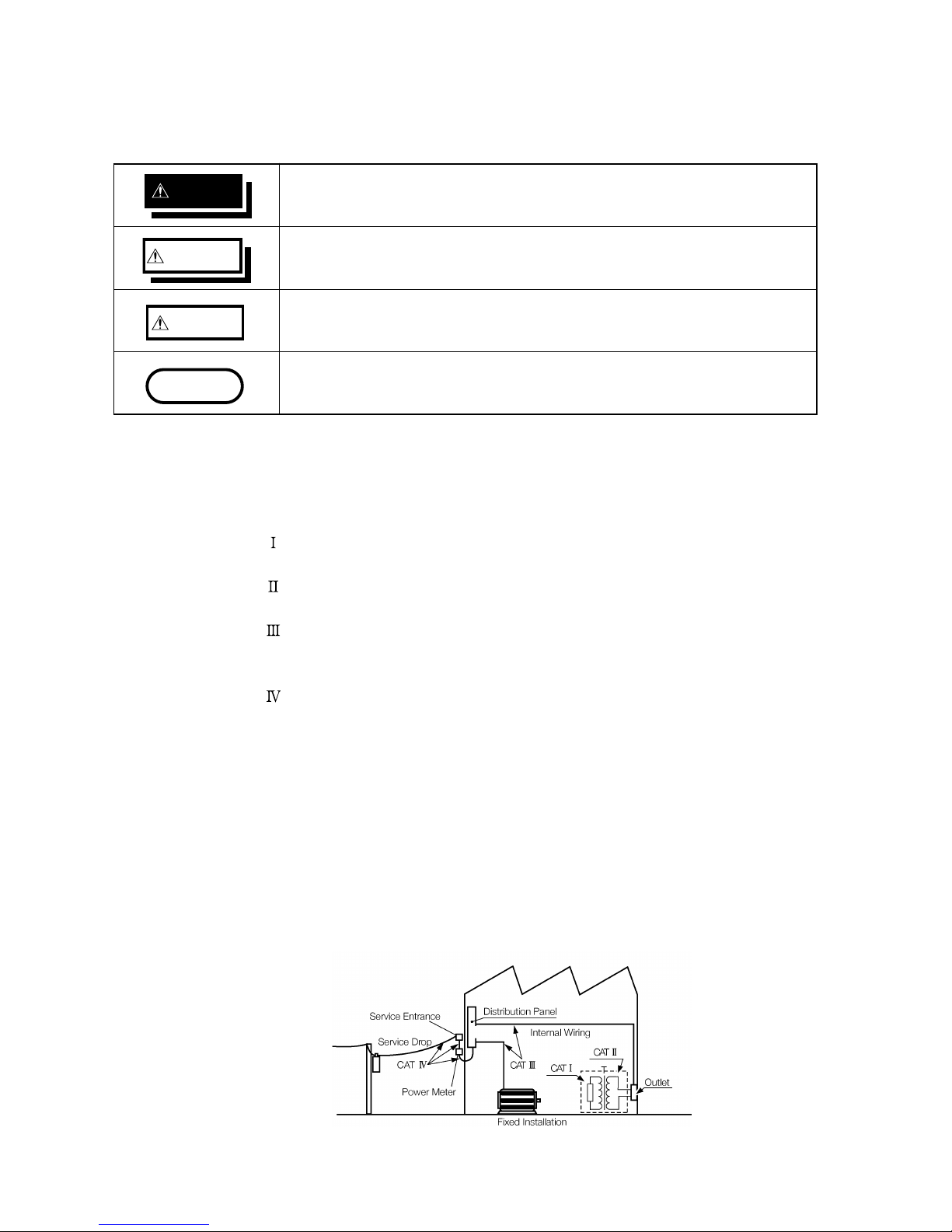
Measurement categories (Overvoltage categories)
This instrument complies with CAT II safety requirements.
To ensure safe operation of measurement instruments, IEC 61010 establishes
safety standards for various electrical environments, categorized as CAT I to
CAT IV, and called measurement categories. These are defined as follows.
CAT
: Secondary electrical circuits connected to an AC electrical outlet
through a transformer or similar device.
CAT
: Primary electrical circuits in equipment connected to an AC electrical
outlet by a power cord (portable tools, household appliances, etc.)
CAT
: Primary electrical circuits of heavy equipment (fixed installations)
connected directly to the distribution panel, and feeders from the
distribution panel to outlets.
CAT
: The circuit from the service drop to the service entrance, and to the
power meter and primary overcurrent protection device (distribution
panel).
Higher-numbered categories correspond to electrical environments with
greater momentary energy. So a measurement device designed for CAT III
environments can endure greater momentary energy than a device designed
for CAT II. Using a measurement instrument in an environment designated
with a higher-numbered category than that for which the instrument is rated
could result in a severe accident, and must be carefully avoided.
Never use a CAT I measuring instrument in CAT II, III, or IV environments.
The measurement categories comply with the Overvoltage Categories of the
IEC60664 Standards.
Page 17
v
────────────────────────────────────────────────────
Notes on Use
────────────────────────────────────────────────────
WARNIN
G
Do not use the product where it may be exposed to corrosive or
combustible gases. The product may be damaged or cause an explosion.
CAUTIO
N
・This product should be installed and operated indoors only, between 5 and
40℃ and 35 to 80% RH.
・Do not store or use the product where it could be exposed to direct sunlight,
high temperature or humidity, or condensation. Under such conditions, the
product may be damaged and insulation may deteriorate so that it no longer
meets specifications.
・This product is not designed to be entirely water- or dust-proof. To avoid
damage, do not use it in a wet or dusty environment.
WARNIN
G
Before turning the product on, make sure the source voltage matches
that indicated on the product’s power connector. Connection to an
improper supply voltage may damage the product and present an
electrical hazard.
Before making connections, make sure the 9439 DC POWER ADAPTER
is turned off. The 8835-01 could be damaged by a spark if it is
connected to a voltage source while its power supply is on.
WARNIN
G
To avoid electric shock and ensure safe operation, connect the power
cable to a grounded (3-contact) outlet.
N
otes on Use
Follow these precautions to ensure safe operation and to obtain the full
benefits of the various functions.
(1) Installation environment
(2) Power supply connections
・Check that the power supply is correct for the rating of the unit. (The AC
fuse is integrated in the unit.)
・The AC power power switch on 8835-01 is for AC power. If DC power is
being supplied and the switch on DC power adapter is set to ON, the 883501 will operate also if the power switch is set to OFF.
(3) Grounding the unit
Page 18
vi
────────────────────────────────────────────────────
Notes on Use
────────────────────────────────────────────────────
DANGE
R
Maximum input voltage ratings for the 8936 ANALOG UNIT, 8937
VOLTAGE/TEMP UNIT, 8938 FFT ANALOG UNIT, 8939 STRAIN UNIT 8940
F/V UNIT, 8946 4ch ANALOG UNIT, 8947 CHARGE UNIT and input
terminals of the 8835-01 are shown below. To avoid the risk of electric
shock and damage to the unit, take care not to exceed these ratings.
The maximum rated voltage to earth of the 8936, 8937, 8938, 8939, 8940,
8946 and 8947 (voltage between input terminals and 8835-01 frame
ground, and between inputs of other input units) is shown below. To
avoid the risk of electric shock and damage to the unit, take care that
voltage between channels and between a channel and ground does not
exceed these ratings.
The maximum rated voltage to earth rating applies also if an input
attenuator or similar is used. Ensure that voltage does not exceed these
ratings.
When measuring power line voltages, 8936 or 8938 should only be
connected to the secondary side of a breaker, so the breaker can
prevent an accident if a short circuit occurs. Connections should never
be made to the primary side of a breaker, because unrestricted current
flow could cause a serious accident if a short circuit occurs.
Always use the optional connection cables. Any exposed metal sections
in a connection cable consist a risk of electric shock.
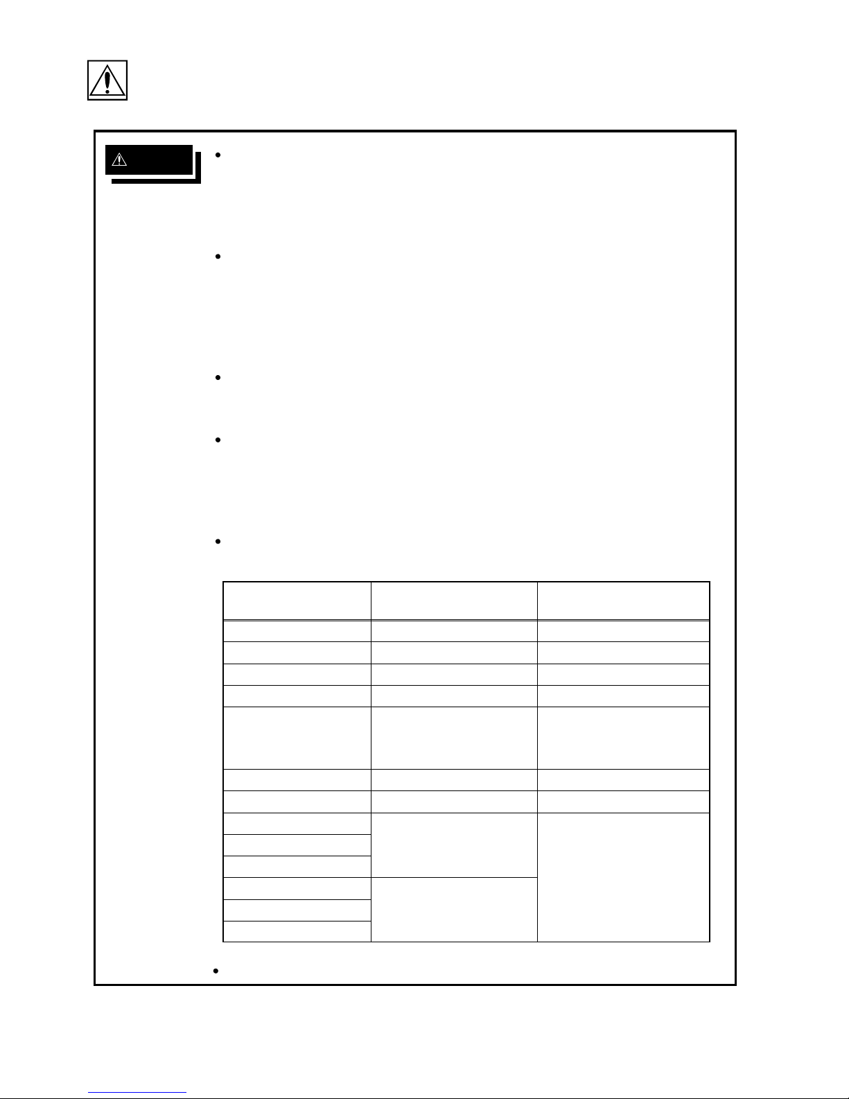
Input/output terminalMaximum input voltage
Maximum rated voltage
to earth
8936 inputs
400 VDC max. 370 V AC/DC
8937 inputs
30 V rms or 60 VDC 30 V rms or 60 VDC
8938 inputs
400 VDC max. 370 V AC/DC
8939 inputs
10 VDC max. 30 Vrms or 60 VDC
8940 inputs
30 V rms or 60 VDC
(BNC and sensor
connector terminals)
30 V rms or 60 VDC
(BNC terminal)
Not insulated
(Sensor connector termina
l)
8946 inputs
30 V rms or 60 VDC 30 V rms or 60 VDC
8947 inputs
30 V rms or 60 VDC 30 V rms or 60 VDC
EXT TRIG
-5 to +10 VDC
Not insulated
START/STOP
PRINT/EXT SMPL
TRIG OUT
-20 V to +30 VDC
100 mA max.
200 mW max.
GO
NG
The external I/O terminal and the 8835-01 have a common GND.
(4) Probe Connection, Measurement Voltage Input
Page 19
vii
────────────────────────────────────────────────────
Notes on Use
────────────────────────────────────────────────────
DANGE
R
Logic probe input and 8835-01 share the same GND. Separate power
supply sources applied to the testing device and 8835-01 may result in
risk of electric shock and damage to the unit.
Even with the same power supply source, certain ways of wiring may
cause a variance in electric potential sending current that may damage
testing device and 8835-01. The following shows proper wiring to avoid
damage. For details, see Section 2.5.
(1) Before connecting logic probe to testing device, connect grounded
three-core power cord (attachment) to the device to be tested and
8835-01 and supply power from the same outlet.
(2) Before connecting logic probe to device to be tested, connect GND of
device to be tested with 8835-01 functional ground terminal. Make
sure that power is supplied from the same outlet.
When using grabber clips, the 9322’s maximum rated voltage to earth is
1500 V AC/DC; when using alligator clips, it is 1000 VAC/DC. To avoid
electrical shock and possible damage to the unit, never apply voltages
greater than these limits between the input channel terminals and
chassis, or across the inputs of two 9322s.
Maximum input voltage is 1000 VAC/2000 VDC. Do not measure voltage
in excess of these limitations, as doing so may damage the unit or
cause an accident that might result in injury or death.
CAUTIO
N
・Use designated connection cables only. Other cables may interfere with
proper connection and measurement accuracy.
・Maximum charge input for miniature connecter terminal in 8947 CHARGE
UNIT is +, - 500 pC (at range 6 high sensitivity) and +, - 50000 pC (at range
6 low sensitivity).
NOTE
WARNIN
G
To avoid electric shock accident, before removing or replacing an input
module, confirm that the instrument is turned off and that the input
cords and power cords are disconnected.
To avoid the danger of electric shock, never operate the product with an
input module removed. To use the product after removing an input
module, install a blank panel over the opening of the removed module.
Use only the specified connection cord. Using a non-specified cable may result
in incorrect measurements due to poor connection or other reasons.
(5) Replacing the input units (see Section 15.3)
Page 20
viii
────────────────────────────────────────────────────
Notes on Use
────────────────────────────────────────────────────
NOTE
NOTE
CAUTIO
N
For shipping or long-term storage, be certain that the recording head is in the
raised position. Otherwise the rollers could be deformed and cause uneven
printing.
CAUTIO
N
・Remove the printer paper from the unit. If the paper is left in the unit, paper
support parts may be damaged due to vibrations.
・To avoid damage to the product, be sure to remove the PC card and floppy
disk before shipping.
・Use the original packing materials when reshipping the product, if possible.
NOTE
WARNIN
G
Before using the product, make sure that the insulation on the cords and
probes is undamaged and that no bare conductors are improperly
exposed. Using the product under such conditions could result in
electrocution. Replace the cords and probes specified by HIOKI.
(6) Recording paper
・ This unit uses a thermal printer. The recording paper supplied has
characteristics finely tuned for use with the printer.
Using recording paper of a different specification may not only result in
impaired printing quality, but even prevent the printer from operating.
Always use the HIOKI specified product.
・ Insert the paper with correct orientation (see Section 2.7).
(7) Using a printer
Avoid using the printer in hot, humid environments, as this can greatly reduce
printer life.
(8) Storing
(9) Shipping
(10) Others
・ In the event of problems with operation, first refer to Section 16.3,
"Troubleshooting."
・ Carefully read and observe all precautions in this manual.
Preliminary Checks
Before using the product the first time, verify that it operates normally to
ensure that the no damage occurred during storage or shipping. If you find
any damage, contact your dealer or HIOKI representative.
Page 21

ix
────────────────────────────────────────────────────
Chapter Summary
────────────────────────────────────────────────────
C
hapter Summary
Chapter 1 Product Overview
Contains an overview of the unit and its features.
Chapter 2 Setup and Preparations
Explains how to set the unit up for measurement.
Chapter 3 Operation Steps for Basic Measurement
Explains how to operate the keys and JOG/SHUTTLE control for carrying out
basic measurement functions.
Chapter 4 Memory Recorder Function Settings
Explains how to use the memory recorder functions of the unit.
Chapter 5 Recorder Function Settings
Explains how to use the recorder functions of the unit.
Chapter 6 RMS Recorder Function Settings
Explains how to use the RMS recorder functions of the unit.
Chapter 7 Input Channel Settings (For all functions)
Explains how to make settings using the channel setting screen.
Chapter 8 Trigger Functions
Explains how to use the trigger functions of the unit.
Chapter 9 System Screen Settings
Explains how to make settings using the system setting screen.
Chapter 10 Printout of Waveform Data
Explains how to print out waveform data and how to read printed charts.
Chapter 11 Using the A/B Cursors / Waveform Scrolling
Explains how to use the A/B cursors and how to perform waveform scrolling.
Chapter 12 External Input/Output Connectors / Key Lock Function
Gives specifications and usage details of the external input/output connectors,
and explains how to use the key lock function.
Page 22

x
────────────────────────────────────────────────────
Chapter Summary
────────────────────────────────────────────────────
Chapter 13 Storing, Recalling and Deleting Waveform Data and Measurement
Settings
Explains how to store, recall, and delete waveform data and measurement
settings.
Chapter 14 Specifications
Contains general specifications and detailed function specifications.
Chapter 15 Logic Input Section and Analog Input Unit
Contains specifications and precautions for logic input section and input
amplifier units.
Chapter 16 Maintenance
Describes maintenance procedures.
Appendix
Contains information that is necessary for using this unit, including a
description of error messages and a glossary.
Page 23

1
────────────────────────────────────────────────────
1.1 Major Features
────────────────────────────────────────────────────
1
2
3
4
5
6
7
8
9
10
11
12
13
14
A
Chapter
1
Product Overvie
w
1
.1 Major Features
(1) Easy to read, TFT color display
The 6.4-inch TFT color screen with a resolution of 640 × 480 dots shows all
information at a glance.
(2) Three functions to meet a huge range of applications
・Memory recorder with up to 1 μs (all channels simultaneously) (1 MS/s)
・Real-time recording capability to paper in recorder function
・RMS recorder function for recording rms values of AC power supply lines and
DC sources.
(3) Flexible trigger function
・Digital trigger circuit
・Trigger types: level trigger, window-in trigger, window-out trigger, voltage
drop trigger, RMS level trigger, logic trigger
(4) Built-in thermal printer
・Thermal line head
・The built-in printer delivers waveform printouts on the spot.
・The printer can also be used to print screen shots and parameter information.
(5) 1 μs (1 MS/s) recording capability
Using the 8946 4 ch ANALOG UNIT (unbalanced), waveform recording can be
performed in up to 8 channels with 12-bit resolution.
(6) Simple function key interface (GUI)
Thanks to its GUI-inspired design using large function key graphics, the unit
is easy to set up and operate.
Page 24

2
────────────────────────────────────────────────────
1.1 Major Features
────────────────────────────────────────────────────
(7) On-line help
On-line help guides the user through operation steps and various functions.
(8) Scaling function
By setting the physical amount and the unit to be used for 1 V input, the
measurement result can be converted into any desired scale.
(9) Additional recording function
When enabled, the memory is regarded as printer paper.
New data is recorded without erasing the previous data.
(10) Floating input units
The analog inputs are floating, and so each input can be connected to its own
independent potentials.
(11) Portable
The 8835-01 weighs only 4.5 kg and has an A4-size form factor, making it
extremely portable.
(12) Floppy disk, PC card (external storage)
Waveform data and measurement settings can be stored on floppy disk or PC
card.
(13) Easy-to-use control panel
Measurement conditions can be easily set while looking at the color display.
Operation keys are few, making setting easy.
(14) External interface
The PC card slot is compatible with GP-IB, RS-232C and 10BASE-T LAN
cards. Remote control is possible.
(15) Dual-language capability
Display language is switchable between Japanese and English.
Page 25

3
────────────────────────────────────────────────────
1.1 Major Features
────────────────────────────────────────────────────
1
2
3
4
5
6
7
8
9
10
11
12
13
14
A
8835 Max 4 analog channels and 16 logic channels
8835-01 Max 8 analog channels and 16 logic channels
8835 (1) Frequency, (2) Count, (3) Pulse duty ratio, (4) Voltage
8835-01 (1) Frequency, (2) Count, (3) Pulse duty ratio, (4) Voltage (5) Current
8835 Installed Memory: 500K words (expandable to 2M words)
8835-01 Installed Memory: 4M words (not expandable)
8835 Waveform: Approx. 10 years, Settings: Approx. 10 years (at 25℃)
8835-01 Waveform: Approx. 1 hour, Settings: Approx. 10 years (at 25℃)
Enhancements over the 8835
(1) Supports the 8946 4ch ANALOG UNIT
The 8946 4ch ANALOG UNIT, which is not compatible with the Model 8835,
can be used to provide up to eight analog measurement channels with the
8835-01.
(2) Supports the current measurement mode of the 8940 F/V UNIT
Current measurement modes not available with the 8835 can be used. The
available 8940 measurement modes are as follows.
(3) Eight times the memory capacity of the 8835
The installed memory capacity of the 8835-01 is eight times that of the 8835.
(4) External sampling provided as standard
The external sampling function is provided as standard with the 8835-01.
Specification Changes from the 8835
Specification Changes from the 8835
Waveform backup time for the 8835-01 is shorter than for the 8835. When
power is turned off after being on for more than two minutes, the waveforms
are backed up for about one hour.
Page 26
4
────────────────────────────────────────────────────
1.2 Basic and Advanced Versions
────────────────────────────────────────────────────
1
.2.1 Additional Features
Measurement functio
n
Feature Version
Memory recorder High-speed data saving Basic version
Recorder Real time recording
RMS recorder For commercial power supplies
Recorder & Memory Real time recording & High-
speed data saving
Advanced version
(incorporates the
basic version)
FFT Frequency analysis
1
.2 Basic and Advanced Versions
This section explains the features of the basic version and the advanced
version. It is possible to upgrade the basic version to the advanced version,
using the feature upgrade disk available as an option.
The following features and functions can be added to the basic version.
Measurement functions
Measurement functions are listed in the table below.
The basic version incorporates the "memory recorder function", "recorder
function", and "RMS recorder function". In addition to these functions, the
advanced version incorporates "recorder & memory" and the "FFT function".
Computation functions
Waveform processing calculation:
Arithmetic operations, absolute value, exponents, common logarithms, moving
average, 1st and 2nd derivatives, 1st and 2nd integrals, time axis parallel
shift
Averaging function:
Additive averaging, exponential averaging (2, 4, 8 to 256 samples) (memory
recorder)
Simple averaging, exponential averaging, peak hold (2, 4, 8 to 4096 samples)
(FFT)
Waveform decision function
Waveform area decision:
Waveform decision based on reference area for Y-T waveform, X-Y waveform,
or FFT results
Waveform parameter decision:
Decision based on setting minimum and maximum values for waveform
parameter calculation results
Page 27

5
────────────────────────────────────────────────────
1.2 Basic and Advanced Versions
────────────────────────────────────────────────────
1
2
3
4
5
6
7
8
9
10
11
12
13
14
A
Memory segmentation function
Memory can be segmented among channels. (255 segments)
Sequential save function
This function does not update the display indication or record data on the
printer or external storage. Input signal capture is carried out continuously
using the trigger.
Multi-block function
Waveform data can be stored in a selected block.
Waveform data in specified blocks can be superimposed.
Page 28
6
────────────────────────────────────────────────────
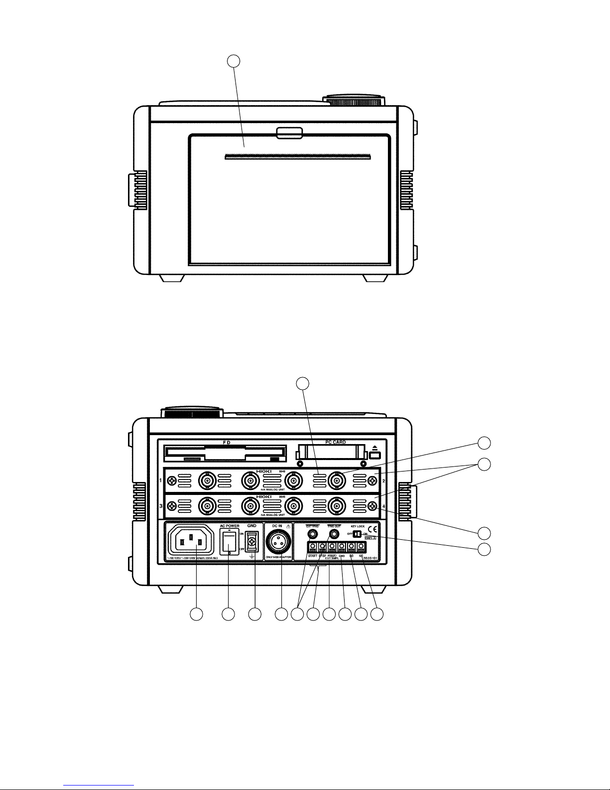
1.3 Identification of Controls and Indicators
────────────────────────────────────────────────────
1716741235689101112131819
20
21
151422
23
Front panel
1
2
3
4
5
1
.3 Identification of Controls and Indicators
Controls and indicators of the unit are listed on the following pages, along
with a simple explanation of their function.
STATUS key Causes the display to show the STATUS screen which
serves for setting most measurement parameters.
CHAN key Causes the display to show the CHANNEL screen which
serves for making input channel settings.
DISP key Causes the display to show measurement and analysis
results.
SYSTEM key Causes the display to show the SYSTEM screen which
serves for making system-wide settings such as for the
scaling function.
FILE key Causes the display to show the FILE screen which
serves for reading, storing, etc. the waveform data etc.
Page 29

7
────────────────────────────────────────────────────
1.3 Identification of Controls and Indicators
────────────────────────────────────────────────────
1
2
3
4
5
6
7
8
9
10
11
12
13
14
A
6
7
8
9
1
0111213
1
4
1
5
1
6
1
7181920212223
HELP key Provides on-line help.
PRINT key Serves to print out stored waveforms.
COPY key Serves to print out a hard copy of the current screen
display.
FEED key Causes the printer paper to advance for as long as the
key is pressed.
CURSOR keys These keys serve to move the flashing cursor in the four
directions.
Open auto range function.
Select key Selects the function that is controlled by the
JOG/SHUTTLE knob. With each push of the key, the
functions is toggled between WAVE and A.B CSR. The
respective LED lights up.
JOG key Rotary control knob that serves to change values, move
the A/B cursors, and scroll the waveform.
SHUTTLE key Concentric ring that serves to move the A/B cursors, and
to scroll the waveform. The speed of movement is
proportional to the rotation angle.
MANU TRIG key Serves to cause manual triggering.
VIEW key Serves to indicate the position of the currently displayed
screen information in relation to the entire recording
length.
F1 - F5 keys Serve to select setting items.
LCD screen
START key Initiates the measurement and analysis. During
measurement, the LED above the key is lit.
STOP key Stops measurement and analysis.
INPUT RANGE key Serves to set the voltage axis range for each channel.
POSITION key Serves to set the zero position for each channel.
CH SELECT key Switches selected channel window.
TIME/DIV key Serves to set the speed for inputting and storing the
input signal.
Page 30
8
────────────────────────────────────────────────────
1.3 Identification of Controls and Indicators
────────────────────────────────────────────────────
1
Left side view
742
35689101112151314
16
Right side view
Page 31

9
────────────────────────────────────────────────────
1.3 Identification of Controls and Indicators
────────────────────────────────────────────────────
1
2
3
4
5
6
7
8
9
1
0111213141516
Printer
AC POWER switch Serves to turn the unit on and off.
Functional ground Connects to the earth.
terminal (GND)
AC connector The supplied power cord must be plugged in here.
Input unit slots These slots accept input units.
Analog input connector (on ANALOG UNIT) Unbalanced analog input
Ventilation slots
Fastening screw Secures the plug-in unit.
Trigger connectors Can be used to synchronize multiple units, using the
EXT TRIG input and TRIG OUT output.
KEY LOCK switch When this switch is set to ON, all keys of the 8835-01
are inactive. The key lock condition is maintained also
when the power is switched off and on again.
External start/stop Start and stop operation can be controlled via external
terminals signals.
External print/ Controls printing or sampling via external signals.
sampling terminal Switches automatically with time axis range settings.
NG evaluation output When the waveform evaluation based on waveform
terminal parameters has resulted in NG, a signal is output from
this terminal.
GO evaluation output When the waveform evaluation based on waveform
terminal parameters has resulted in GO, a signal is output from
this terminal.
DC power supply Allows use of an external DC source to power the unit
connector (with dedicated DC POWER ADAPTER).
Ground terminal Common GND (
3
Function ground terminal) with the
(GND) 8835-01. Use with
11to14
terminals.
Page 32

10
────────────────────────────────────────────────────
1.3 Identification of Controls and Indicators
────────────────────────────────────────────────────
231
Top view
4
5
Bottom view
1
2
3
4
5
Ventilation slots
Handle Serves for transporting the 8835-01.
Logic probe connectors Input connector for the logic input section, designed for
the dedicate logic probes (CH A, CH B, CH C, CH D).
Ventilation slots
Tilt support
Page 33

11
────────────────────────────────────────────────────
────────────────────────────────────────────────────
1
2
3
4
5
6
7
8
9
10
11
12
13
14
A
Chapter
2
Installation and Preparatio
n
Page 34

12
────────────────────────────────────────────────────
2.1 Installation of the Unit
────────────────────────────────────────────────────
2
.1 Installation of the Unit
Installation orientation
Install the unit on a flat, level surface.
The unit can also be propped up at an angle, using the stand.
Page 35

13
────────────────────────────────────────────────────
2.1 Installation of the Unit
────────────────────────────────────────────────────
1
2
3
4
5
6
7
8
9
10
11
12
13
14
A
Ventilatio
n
NOTE
Ambient conditions
Temperature 5to40℃,23±5℃ recommended for high-precision
measurements
Humidity 35 to 80%RH (no condensation); 50±10%RH (no
condensation) recommended for high-precision measurements
Ventilation Take care not to block the ventilation openings and assure
proper ventilation. When using the unit in an upright
position, take care not to block the openings on the bottom, as
it could overheat and be damaged, or cause a fire.
Avoid the following locations:
・Subject to direct sunlight
・Subject to high levels of dust, steam, or corrosive gases
(Avoid using the equipment in an environment containing corrosive gases
(e.g., H
2
S, SO
2
,NI
2
, and CI
2
) or substances that generate harmful gasses
(e.g., organic silicones, cyanides, and formalins)).
・Subject to vibrations
・In the vicinity of equipment generating strong electromagnetic fields
Page 36

14
────────────────────────────────────────────────────
2.2 Power Supply and Ground Connection
────────────────────────────────────────────────────
WARNIN
G
Take care never to exceed the power supply ratings given below, to avoid
the risk of electric shock and damage to the unit.
NOTE
WARNIN
G
The 8835-01 has no protective ground terminal, but is intended to be
connected to a ground wire via the grounded three-core power cord
supplied. To avoid electric shock and ensure safe operation, connect the
power cable to a grounded (3-contact) outlet.
2
.2 Power Supply and Ground Connection
The fuse is incorporated in power supply. It is not user-replaceable. If a
problem is found, contact your dealer or HIOKI representative.
Power supply, fuse
Rated power supply voltage 100 to 120 V AC / 200 to 240 V AC
(auto-switching)
(Voltage fluctuations of 10% from the rated
supply voltage are taken into account.)
Rated AC power supply frequency 50/60 Hz
Fuses AC incorporated in power supply
(not user-replaceable)
Grounding
・When the AC outlet is of the grounded three-pin type:
Use the grounded three-core power cord supplied. The unit will be grounded
automatically.
・When the AC outlet is not of the grounded three-pin type:
Use the ground adapter supplied. In this case, be absolutely sure to connect
the green ground wire which protrudes from the adapter to a ground line,
and connect the power cord supplied.
Check the following points before connecting the unit to a power supply:
・The power supply matches the ratings shown above.
・The AC power switch of the 8835-01 and the switch of the 9439 DC POWER
ADAPTER are set to OFF.
・Use only the supplied AC power cord.
Page 37

15
────────────────────────────────────────────────────
2.2 Power Supply and Ground Connection
────────────────────────────────────────────────────
1
2
3
4
5
6
7
8
9
10
11
12
13
14
A
WARNIN
G
Make sure that the AC power switch of the 8835-01 is set to OFF.
AC power connector
AC power switch
Rated voltage:
100 - 120 V AC / 200 - 240 V AC
Rated line frequency:
50/60 Hz
Connecting the unit to a power supply and grounding it:
(1) AC power supply
1. Verify that the AC power switch of the 8845 is set to OFF.
2. Plug the grounded three-core power cord supplied into the AC power connector
on the right side of the 8835-01.
3. Plug the power cord into an AC outlet corresponding to the rating of the 8835-
01.
Page 38

16
────────────────────────────────────────────────────
2.2 Power Supply and Ground Connection
────────────────────────────────────────────────────
DANGE
R
Before connecting the unit to a battery or other DC source, make sure
that the switch of the 9439 DC POWER ADAPTER is set to OFF. If the
switch is ON, there is a risk of sparks, and the unit may be damaged.
WARNIN
G
Before making connections, make sure the 9439 DC POWER ADAPTER
is turned off. The 8835-01 could be damaged by a spark if it is
connected to a voltage source while its power supply is on.
The rated supply voltage of the 9439 DC POWER ADAPTER is 10 to
28 VDC. If an attempt is made to use an improper supply voltage, there
is danger of damage to this unit and of life-threatening risk to the
operator.
The 9439 DC POWER ADAPTER is a power supply and therefore
generates heat. Do not place any object on this equipment nor force it
in to a narrow area for operation.
When connecting the input cable of the 9439 DC POWER ADAPTER,
take care not to mix up the red (+) and black (-) leads. If polarity is
reversed, the 9439 may be damaged.
When wishing to extend DC cable, use a cable of identical or better
rating as the input cable.
The 9439 DC POWER ADAPTER an option specifically designed for the
MEMORY HiCORDER 8835-01. Do not connect this adapter to any other
products.
The switch on the 9439 DC POWER ADAPTER doubles as the breaker.
Accordingly, ensure that there is ample space to operate the switch.
(2) DC power supply
1. Verify that the switch of the 9439 DC POWER ADAPTER is set to OFF.
2. Align the ridge of the connector on the unit with the groove in the plug, insert
the plug fully and rotate it to fix it firmly.
3. Connect the red input cable to the positive side (+) and the black input cable
to the negative side (-) of the power supply.
4. The red LED lights while the unit is operating (outputting).
5. To remove the plug of the DC cable, rotate it as shown in the illustration.
Page 39

17
────────────────────────────────────────────────────
2.2 Power Supply and Ground Connection
────────────────────────────────────────────────────
1
2
3
4
5
6
7
8
9
10
11
12
13
14
A
Rated voltage: 10 to 28 V DC
LED
NOTE
Operation condition 8936 installed
in 4 channels
8940 installed
in 4 channels
8940 2 ch
current testing
Printer not used (trigger waiting) Approx. 12 h Approx. 6 h Approx. 8 h
Printer used
Recorder function
500 ms/DIV, all store
Approx. 5 h Approx. 4 h
Functional ground termina
l
・ This unit is not equipped to charge an external battery.
・ When using a battery, take care not to deplete it completely.
・ When an overcurrent or overvoltage is detected in the output, this
equipment cuts off the output. In such an event, turn off the 9439 DC
POWER ADAPTER, wait for approximately one minute, and then turn the
adapter on again.
・ If an overcurrent flows through the input cord for any reason, this
equipment is automatically turned off to stop operation.
・ Estimated battery operation hours (at room temperature)
Battery type: 12 V, 38 Ah, fully charged
PC card not installed
Actual running time may differ, depending on battery age, charge condition,
ambient temperature, and other factors.
・ Input cable specifications
Permissible current: 15 A
Functional ground terminal
When measuring in a "noisy" environment, noiseproofing can be improved by
grounding the functional ground terminal.
Page 40

18
────────────────────────────────────────────────────
2.3 Power On/Off
────────────────────────────────────────────────────
AC power switch
2
.3 Power On/Off
(1) Check before power-on
・Unit is correctly installed (
Section 2.1).
・Power cord is correctly connected and unit is properly grounded (
Section
2.2).
(2) Power switch on/off
・There is no need for the user to manually select AC or DC power.
・When both AC and DC power are connected, AC power has priority.
・When AC power is disconnected (or falls under 90 V), the 8835-01
automatically switches to DC. (If the switch of the 9439 is set to ON, the
8835-01 automatically switches to DC even if AC power is disconnected.)
(3) To assure high measurement precision
Turn the unit on and let it warm up for about 30 minutes, to allow internal
temperature to fully stabilize. Then carry out zero adjustment (see Section
7.3.7) and start the measurement.
(4) Power-off
When the unit is turned off, it memorizes the currently used settings and
reestablishes the same settings the next time the unit is turned on again.
Page 41

19
────────────────────────────────────────────────────
2.4 Probe Connection
────────────────────────────────────────────────────
2
.4.1 8936 ANALOG UNIT, 8938 FFT ANALOG UNIT and
8946 4 ch ANALOG UNIT
WARNIN
G
Never connect the probe to the 8835-01 while the probe is already
connected to the measurement object. Otherwise there is a risk of
electric shock.
Use only the specified connection cables. An insulated BNC connector
is used for the specified connection cables to prevent electric shock. If
a metal BNC connector is used, electric shock may result, as the input
L-terminal and the metal part of the BNC connector will have the same
potential.
CAUTIO
N
When disconnecting the BNC connector, be sure to release the lock before
pulling off the connector. Forcibly pulling the connector without releasing the
lock, or pulling on the cable, can damage the connector.
NOTE
9197 CONNECTION CORD
(Maximum input voltage: 500 V)
9198 CONNECTION CORD
(Maximum input voltage: 300 V)
9217 CONNECTION CORD
(Maximum input voltage: 300 V)
Connector ridg
e
2
.4 Probe Connection
Use only the specified connection cables. Using a non-specified cable may
result in incorrect measurements due to poor connection or other reasons.
In addition, the BNC connector may be damaged.
For analog input connection, use optional 9197, 9198 CONNECTION CORDs.
Use of any other cables may result in risk of electric shock.
For connecting 8946, use 9198 CONNECTION CORD.
Connecting to the main unit
1. Align the BNC connector with the guide groove of the unit input connector,
and turn clockwise while pressing in to lock the connector.
2. To remove from the unit, turn the BNC connector counterclockwise to release
the lock, then pull it.
Page 42

20
────────────────────────────────────────────────────
2.4 Probe Connection
────────────────────────────────────────────────────
1
2563478
2
.4.2 8937 VOLTAGE/TEMP UNIT
WARNIN
G
Never connect the connection cable to the 8835-01 while the connection
cable is already connected to the measurement object. Otherwise there
is a risk of electric shock.
A common GND is used for voltage and temperature input on all
channels. Never input voltage and temperature simultaneously, since
doing so could result in damage to the sample being tested.
When an uninsulated thermocouple is used to measure temperature at a
point carrying electric potential, take care not to touch the terminals.
Otherwise there is a risk of electric shock.
The voltage and temperature input and the 8835-01 frame are insulated.
CAUTIO
N
・When disconnecting the BNC connector, be sure to release the lock before
pulling off the connector. Forcibly pulling the connector without releasing the
lock, or pulling on the cable, can damage the connector.
・Use a screwdriver or similar to attach and remove the thermocouple.
Setting Channels in 8946 4 ch ANALOG UNIT
When using 8946 4 ch ANALOG UNIT, input channels are not numbered in
numeric order as 1,2,3,4. Channel number is determined by connection to
units. (See below.) To verify position of channels, see Channel Guide.
Connection cable connection (Voltage measurement)
For measuring voltage with 8937, use 9198 CONNECTION CORD.
1. Align the BNC connector with the guide groove of the unit input connector,
and turn clockwise while pressing in to lock the connector.
2. To remove from the unit, turn the BNC connector counterclockwise to release
the lock, then pull it.
Page 43

21
────────────────────────────────────────────────────
2.4 Probe Connection
────────────────────────────────────────────────────
25 mm
10 mm
Thermocouple lead
s
Inner insulatio
n
Outer insulation (mantle
)
NOTE
Thermocouple connection (Temperature measurement)
1. Strip off the insulation as shown in the illustration.
2. Push the tab with a screwdriver or similar.
3. While keeping the tab depressed, insert a stripped thermocouple into the
connector openings.
4. Release the tab to lock the thermocouple.
5. While keeping the tab depressed, remove the thermocouple.
・The press-button type terminal board of the 8937 VOLTAGE/TEMP UNIT is
only for connection to a thermocouple. Do not use thermocouples other than
the specified types (K, J, E, T, N, R, S, B).
・If the thermocouple is connected in reverse, the temperature reading will
not be correct.
・If the temperature input terminal is exposed to a strong draft, loss of
thermal equilibrium at the input may result in measurement error. When
taking measurements under such conditions, arrange the unit in such a
manner that the input terminal is protected for direct exposure to drafts.
・If ambient temperature changes suddenly, loss of thermal equilibrium can
result in measurement error. When this occurs, allow the unit to acclimate
to the new temperature for about one hour, then take measurements after
thermal equilibrium is reached.
Page 44

22
────────────────────────────────────────────────────
2.4 Probe Connection
────────────────────────────────────────────────────
2
.4.3 8939 STRAIN UNIT
CAUTIO
N
・Connect only the sensor to the conversion cable supplied with the 8939
STRAIN UNIT.
・To disconnect the conversion cable, always unlock the plug and pull out the
cable.
Projection on the unit connector
Cutout on the conversion cable
Fixing guide
Connector ridge
B
ridge voltage:2
V
(Apply voltage)
−
+
+−Input voltage
Connecting to the main unit
1. Align the projection on the unit connector with the cutout on the conversion
cable, and insert the plug into the connector.
2. Turn the fixing guide (the colored area in the figure below) so that it engages
with the connector guides on the unit, fully insert the fixing guide, and turn it
clockwise to lock the plug.
3. To remove the conversion cable from the unit, turn the fixing guide (the
colored area in the figure below) counterclockwise to unlock the plug, and pull
out the plug.
Connector
Page 45

23
────────────────────────────────────────────────────
2.4 Probe Connection
────────────────────────────────────────────────────
2
.4.4 8940 F/V UNIT
DANGE
R
To avoid electrical accidents, make sure that the MEMORY HiCORDER
and the equipment being measured are powered off before making
connections. Do not make connections with the power turned on.
When using the 9318 or 9319 CONVERSION CABLE, there is no isolation
between GND the MEMORY HiCORDER and GND of the clamp on
sensor/probe. Exercise extreme care in connection to avoid possible
damage to the equipment or personal injury.
When connecting 8940 F/V UNIT to 3273 or 3273-50, and conductors
being measured carry in excess of the safe voltage level (SELV-E) and
not more than 300 V, to prevent short circuits and electric shock while
the core section is open, make sure that conductors to be measured
are insulated with material conforming to (1) Overvoltage Category l
, (2)
Double Insulation (Reinforced insulation) Requirements for Working
Voltage of 300 V, and (3) Pollution Degree 2. For safeties sake, never
use this sensor on bare conductors. The core and shield case are not
insulated.
When connecting 8940 F/V UNIT to 3273 or 3273-50, do not damage
insulation sheathing on testing device.
Refer to the following standards regarding the meanings of underlined
terms. IEC 61010-1, IEC 61010-2-031, IEC 61010-2-032
WARNIN
G
When using the clamp-on sensor or clamp-on probe, be sure to use the
optional 9318 or 9319 CONVERSION CABLE.
CAUTIO
N
・When disconnecting the BNC connector, be sure to release the lock before
pulling off the connector. Forcibly pulling the connector without releasing the
lock, or pulling on the cable, can damage the connector.
・When using the Model 3273-50 with the 8940, bear in mind that the
maximum input of the 3273-50 is 15 Arms. Exceeding this measurement
level could damage the instrument.
Groove of the BNC
Connector guide
Connection cable connection (Frequency, count, pulse duty ratio and voltage measurement)
Use the optional 9198 CONNECTION CORD for
connection to the F/V UNIT.
1. Align the BNC connector with the guide groove of the
8826 input connector, and turn clockwise while pressing
in to lock the connector.
2. To remove from the unit, turn the BNC connector
counterclockwise to release the lock, then pull it.
Clamp connection (Current measurement)
The following clamp-on sensors and clamp-on probes can be connected using
the 9318 and 9319 CONVERSION CORDs.
9318:9270, 9271, 9272, 9277, 9278, 9279, 9319:3273
Page 46

24
────────────────────────────────────────────────────
2.4 Probe Connection
────────────────────────────────────────────────────
Adapted clamp’s plu
g
Unit’s sensor connecto
r
Conversion cable plu
g
Conversion cable connecto
r
Unit’s BNC connecto
r
3273 or 3273-50
*1
connecto
r
Unit’s senso
r
connector
Conversion
cable plug
Connecting to 9318 CONVERSION CABLE
1. Align the groove on the conversion cable plug with the sensor connector on the
F/V unit and push inward until the connector locks into place.
2. Align the groove on the conversion cable connector with the adapted clamp on
sensor plug and push inward until the connector locks into place.
3. To unplug the cables, slide the lock ring on each plug outward to unlock it,
then pull out the plug. When disconnecting the connector and the plug, hold
the connector or the plug, and pull carefully. Pulling on the cable instead of
the connector or the plug may damage the connector and cable.
Connecting to 9319 CONVERSION CABLE
1. Align the groove on the 3273 or 3273-50
*1
CLAMP ON PROBE’s termination
connector with the pin on the BNC connector on the F/V unit, then slide the
termination connector over the BNC connector and turn to lock it in place.
2. Align the groove on the conversion cable plug with the sensor connector on the
F/V unit and push inward until the connector locks into place.
3. To unplug the cables, unlock the conversion cable connector and the power
plug on the 3273 or 3273-50
*1
before unplugging the cable.
4. Slide the lock ring on each plug outward to unlock it, then pull out the plug.
When disconnecting the connector and the plug, hold the connector or the
plug, and pull carefully. Pulling on the cable instead of the connector or the
plug may damage the connector and cable.
*1: When using the Model 3273-50 with the 8940, bear in mind that the maximum
input of the 3273-50 is 15 Arms.
Page 47

25
────────────────────────────────────────────────────
2.4 Probe Connection
────────────────────────────────────────────────────
2
.4.5 8947 CHARGE UNIT
WARNIN
G
DO NOT connect connection cable to the 8947 CHARGE UNIT when
connected to measuring unit to avoid risk of electric shock.
BNC terminal and miniature connecter terminal of each channel share
same GND. Do not connect both at once.
During measuring with measurement mode set to PREAMP or when
level monitor function is in use, electric current (2 mA, +15 V) output is
active. In order to avoid risk of electric shock and damage to testing
device, examine channel mode for connecting sensor and probe to BNC
terminal and either cancel PREAMP or shut down power.
Voltage measurement and internal acceleration pick up sensor share
same terminal. Make sure to check measurement mode before
measuring.
Before using internal acceleration pickup sensor, verify that sensor
ratingis compatible with 8947 CHARGE UNIT rated output (2 mA, +15 V).
Use of Non compatible sensor may cause damage to sensor.
Connector ridg
e
Connection cable connection (Preamp and voltage measurement)
In preamp mode when connecting unit with pick-up sensor, match BNC cable
to BNC connector.
1. Align the BNC connector with the guide groove of the unit input connector,
and turn clockwise while pressing in to lock the connector. (For connecting
8947, use 9198 CONNECTION CORD.)
2. To remove from the unit, turn the BNC connector counterclockwise to release
the lock, then pull it.
Miniature connecter connection (Charge mode)
For charge testing when connecting unit with pick-up sensor, match cable
connecter to miniature connecter. (miniature connecter terminal 10-32)
1. Plug miniature connecter cable into the cable connecter on the unit.
Tighten the connecter by turning clockwise.
2. To remove connecter, turn the connecter counterclockwise.
Page 48

26
────────────────────────────────────────────────────
2.5 Logic Probe Connection
────────────────────────────────────────────────────
DANGE
R
Logic probe input and 8835-01 share the same GND. Separate power
supply sources applied to the testing device and 8835-01 may result in
risk of electric shock and damage to the unit.
Even with the same power supply source, certain ways of wiring may
cause a variance in electric potential sending current that may damage
testing device and 8835-01. The following shows proper wiring to avoid
damage.
(1) Before connecting logic probe to testing device, connect grounded
three-core power cord (attachment) to the device to be tested and 883501 and supply power from the same outlet (see fig. 1).
(2) Before connecting logic probe to device to be tested, connect GND of
device to be tested with 8835-01 functional ground terminal (see fig. 2).
Make sure that power is supplied from the same outlet.
For the functional ground terminal, see Section 2.2.
Testing
device
8835-01
Outlet
Power
Earth
Fig. 1
8835-01
Functional
g
round termin
al
GND
Fig. 2
Make sure that power is supplied from
the same outlet.
Testing
device
Groove
NOTE
2
.5 Logic Probe Connection
Connecting to the main unit
Connect the probe by aligning the groove on the plug with the ridge on the
connector.
・If no logic probe is connected, the corresponding logic waveform is displayed
on the screen at high level.
・For the 9320 and 9321 LOGIC PROBEs, carefully read the documentations
supplied with them.
・Do not connect logic probes other than supplied by HIOKI to the logic
inputs.
Page 49

27
────────────────────────────────────────────────────
2.6 9322 DIFFERENTIAL PROBE Connection
────────────────────────────────────────────────────
DANGE
R
When using grabber clips, the 9322’s maximum rated voltage to earth is
1500 VAC/DC; when using alligator clips, it is 1000 V AC/DC. To avoid
electrical shock and possible damage to the unit, never apply voltages
greater than these limits between the input channel terminals and
chassis, or across the inputs of two 9322s.
Maximum input voltage is 1000 VAC/2000 VDC. Do not measure voltage
in excess of these limitations, as doing so may damage the unit or
cause an accident that might result in injury or death.
Grabber clip
s
Alligator clip
s
Stock cove
r
2
.6 9322 DIFFERENTIAL PROBE Connection
2
.7 Loading Recoding Paper
9322 is a differential probe that connects to input of 8835-01 MEMORY
HiCORDER input unit. For more details, refer to its instruction manual.
1. Press the stock cover and open it.
Page 50

28
────────────────────────────────────────────────────
2.7 Loading Recoding Paper
────────────────────────────────────────────────────
Printer exit slo
t
Head up/down
lever
9221
RECORDING PAPER
Holde
r
Attachmen
t
Printer rolle
r
2. Raise the head up/down lever.
3. Insert the attachments into the ends of the roll of recording paper and set
the paper into its holder.
4. Insert the leading edge of the recording paper from above into the gap
behind the printer roller, and pull it out to the other side.
5. Pull the end of the recording paper out at least 10 cm, and make sure that
it is positioned quite straight.
6. Put down the head up/down lever.
Page 51

29
────────────────────────────────────────────────────
2.7 Loading Recoding Paper
────────────────────────────────────────────────────
Head up/down
lever
NOTE
7. Pull the recording paper to the outside through the printer exit slot in the
stock cover.
8. Close the stock cover, and finish by tearing off the recording paper against
the edge of the printer exit slot.
・ Always put the unit in the head up condition when it is to be transported or if
it is to be stored for a long period of time. If the unit is left to lie in the state
where the roller is being subjected to pressure by the head, then the roller
may become deformed or the characters may become uneven.
・ Particularly care should be taken not to put the recording paper in back to
front by mistake, because if this happens the waveform cannot be drawn.
・ Printing is not possible if the recording paper is loaded wrong-side up.
・ Do not insert it into the gap between the roller and the black sheet metal
portion.
・ Refer to the illustration to make sure that the correct side of the recording
paper is facing up.
・ Do this very carefully, because if the recording paper is slanted with respect to
the roller there is a danger that later a paper jam will occur.
Page 52

30
────────────────────────────────────────────────────
2.8 Storage and Handling Precautions
────────────────────────────────────────────────────
Direct sunligh
t
Organic solven
t
2
.8 Storage and Handling Precautions
Store rolls of thermal paper at no more than 40℃.
The paper will change color if exposed to light over a long period, so do not
unwrap a roll of paper until you are ready to use it.
Storing data recordings
As the recording paper is thermally sensitive, be aware of the following points:
・To avoid paper discoloration, do not expose it to direct sunlight, and store at
no more than 40℃ and 90% RH.
・For permanent storage of important recorded data, photocopy the recording
paper.
・If the thermal paper is exposed to an organic solvent such as alcohol or
ketone, it may no longer develop properly, and recorded data may fade.
・Also, the thermal recording paper is ruined by contact with wet Daizo copy
paper.
Page 53

31
────────────────────────────────────────────────────
2.9 Notes on Measurement
────────────────────────────────────────────────────
DANGE
R
Maximum input voltage ratings for the 8936 ANALOG UNIT, 8937
VOLTAGE/TEMP UNIT, 8938 FFT ANALOG UNIT, 8939 STRAIN UNIT 8940
F/V UNIT, 8946 4ch ANALOG UNIT, 8947 CHARGE UNIT and input
terminals of the 8835-01 are shown below. To avoid the risk of electric
shock and damage to the unit, take care not to exceed these ratings.
The maximum rated voltage to earth of the 8936, 8937, 8938, 8939, 8940,
8946 and 8947 (voltage between input terminals and 8835-01 frame
ground, and between inputs of other input units) is shown below. To
avoid the risk of electric shock and damage to the unit, take care that
voltage between channels and between a channel and ground does not
exceed these ratings.
The maximum rated voltage to earth rating applies also if an input
attenuator or similar is used. Ensure that voltage does not exceed these
ratings.
When measuring power line voltages, 8936 or 8938 should only be
connected to the secondary side of a breaker, so the breaker can
prevent an accident if a short circuit occurs. Connections should never
be made to the primary side of a breaker, because unrestricted current
flow could cause a serious accident if a short circuit occurs.
Input/output terminalMaximum input voltage
Maximum rated voltage
to earth
8936 inputs
400 VDC max. 370 V AC/DC
8937 inputs
30 V rms or 60 VDC 30 V rms or 60 VDC
8938 inputs
400 VDC max. 370 V AC/DC
8939 inputs
10 VDC max. 30 Vrms or 60 VDC
8940 inputs
30 V rms or 60 VDC
(BNC and sensor
connector terminals)
30 V rms or 60 VDC
(BNC terminal)
Not insulated
(Sensor connector termina
l)
8946 inputs
30 V rms or 60 VDC 30 V rms or 60 VDC
8947 inputs
30 V rms or 60 VDC 30 V rms or 60 VDC
EXT TRIG
-5 to +10 VDC
Not insulated
START/STOP
PRINT/EXT SMPL
TRIG OUT
-20 V to +30 VDC
100 mA max.
200 mW max.
GO
NG
The external I/O terminal and the 8835-01 have a common GND.
2
.9 Notes on Measurement
Page 54

32
────────────────────────────────────────────────────
2.9 Notes on Measurement
────────────────────────────────────────────────────
DANGE
R
In order to avoid accidents from electric shock, before removing or
replacing an input unit, check that the connection cables are
disconnected, turn off the power, and remove the power cable.
Normally keep all input units installed permanently. If a unit is not fitted,
it must be replaced by a blanking panel. If the unit is operated with an
input unit not in place it poses a shock hazard.
When using grabber clips, the 9322’s maximum rated voltage to earth is
1500 V AC/DC; when using alligator clips, it is 1000 V AC/DC. To avoid
electrical shock and possible damage to the unit, never apply voltages
greater than these limits between the input channel terminals and
chassis, or across the inputs of two 9322s.
Maximum input voltage is 1000 VAC/2000 VDC. Do not measure voltage
in excess of these limitations, as doing so may damage the unit or
cause an accident that might result in injury or death.
WARNIN
G
Before using the product, make sure that the insulation on the connection
cords is undamaged and that no bare conductors are improperly
exposed. Using the product under such conditions could result in
electrocution. Replace the connection cords with the specified HIOKI
Model 9197 or 9198.
CAUTIO
N
・When making measurements on an AC power line for example, using a
voltage transformer, be sure to connect the voltage transformer ground
terminal to ground.
・Maximum charge input for miniature connecter terminal in 8947 CHARGE
UNIT is +, - 500 pC (at range 6 high sensitivity) and +, - 50000 pC (at range
6 low sensitivity).
Page 55

33
────────────────────────────────────────────────────
2.9 Notes on Measurement
────────────────────────────────────────────────────
2
.9.1 Using a Voltage Transformer
8835-01
GND terminal
H
L
PT
Voltage transformer
(PT) ground termina
l
Ground
8835-01
GND terminal
PT
Inpu
t
Ground
Inpu
t
When the voltage transformer has no ground termina
l
When the voltage transformer has a ground termina
l
H
L
8936 o
r
8938
8936 o
r
8938
2
.9.2 Maximum Input Voltage
8835-0
1
GND
8936 o
r
8938
H
L
370 VAC, DC
400 VDC max
.
370 VAC, DC
8835-0
1
GND
893
7
894
6
H
L
30 Vrms or 60 VDC
30 Vrms or 60 VDC
30 Vrms o
r
60 VDC
8835-0
1
GND
893
9
H
L
10 VDC max
.
30 Vrms or 60 VDC
30 Vrms o
r
60 VDC
When making measurements on an AC power line for example, using a
voltage transformer, be sure to connect the voltage transformer ground
terminal to ground.
8936 ANALOG UNIT, 8938 FFT ANALOG UNIT
8937 VOLTAGE/TEMP UNIT, 8946 4 ch ANALOG UNIT
8939 STRAIN UNIT
Page 56

34
────────────────────────────────────────────────────
2.9 Notes on Measurement
────────────────────────────────────────────────────
8835-0
1
GND
BNC
H
L
30 Vrms or DC60 V
30 Vrms or DC60 V
Sensor
connector
H
L
30 Vrms o
r
60 VDC
30 Vrms or 60 VDC
894
0
8835-0
1
GND
Miniature
connector
H
L
30 Vrms or 60 VDC
BNC
H
L
30 Vrms o
r
60 VDC
30 Vrms or 60 VDC
894
7
Commo
n
*
*: +, - 500 pC (at range 6 high sensitivity),
+, - 50000 pC (at range 6 low sensitivity
)
AC
+400 V DC
-400 V DC
0
DC DC+AC
8940 F/V UNIT
8947 CHARGE UNIT
Difference between "370 V AC, DC" and "400 V DC max." indication
370 V AC, DC: Rms value is displayed.
400 V DC max.: Instantaneous value is displayed.
The maximum input voltage (400 V DC max.) is defined as the superposition
of DC component and AC peak, as shown in the figure below.
Page 57

35
────────────────────────────────────────────────────
3.1 Basic Operation
────────────────────────────────────────────────────
1
2
3
4
5
6
7
8
9
10
11
12
13
14
A
3
.1.1 Basic Display Operation
STATUS key CHAN key DISP key
SYSTEM ke
y
HELP ke
y
FILE ke
y
Chapter
3
Basic Operation an
d
Measureme
nt
3
.1 Basic Operation
This section explains basic steps and settings for measurement.
STATUS key Calls up the STATUS screen.
Serves to switch pages of the STATUS screen.
Serves to make main settings for various functions on the
STATUS screen.
CHAN key Calls up the CHANNEL screen.
Serves to set voltage axis range, zero position, etc. for input
channels.
Serves to switch pages of the CHANNEL screen.
Using the variable function, you can adjust size and position
of waveform display as desired, even without changing the
range or position settings.
DISP key Calls up the display screen.
Serves to display and observe waveforms.
Page 58

36
────────────────────────────────────────────────────
3.1 Basic Operation
────────────────────────────────────────────────────
3
.1.2 Setting Items
Cursor key
s
Function key
s
SYSTEM key Calls up the SYSTEM screen.
Serves to switch pages of the SYSTEM screen.
Serves to make common settings for all functions (clock
setting, comment input, etc.) on the SYSTEM screen.
HELP key On-line help
An explanation of the display screen or the item currently
selected by the cursor appears.
FILE key Calls up the FILE screen.
Serves to read and store waveform data on the FILE screen.
CURSOR keys Serve to move the flashing cursor.
Pressing the
and keys simultaneously opens auto range
function screen. (Memory recorder)
F1 to F5 Select items.
(Function key) The respective items are shown in the function key display.
Page 59

37
────────────────────────────────────────────────────
3.1 Basic Operation
────────────────────────────────────────────────────
1
2
3
4
5
6
7
8
9
10
11
12
13
14
A
3
.1.3 JOG/SHUTTLE Control and Select Key
Select ke
y
Jog contro
l
Shuttle contro
l
LED
s
Function key display
(GUI)
1
Value up
Move the flashing item selection cursor up in
the selection window.
Value down
Move the flashing item selection cursor down
in the selection window.
2
Value up,
large step
Value up, 10-units
Value up,
small step
Value up, 1-units
Value down
,
small step
Value down, 1-units
Value down
,
large step
Value down, 10-units
Lit LED JOG/SHUTTLE control function
WAVE
Waveform scrolling
A.B CSR
Movement of A/B cursors
Entering numbers and setting items (except on the DISPLAY screen)
Scroll waveform, move A/B cursors
JOG/SHUTTLE control can be used to scroll the waveform and to move the A and
B cursors (for details, refer to Chapter 11).
Switch between waveform scroll and cursor movement
Use the select key when the screen is in measurement display mode.
Page 60

38
────────────────────────────────────────────────────
3.1 Basic Operation
────────────────────────────────────────────────────
3
.1.4 Measurement Start and End
START ke
y
STOP ke
y
LED
3
.1.5 Basic Input Operation
CH SELECT ke
y
TIME/DIV ke
y
POSITION key
s
INPUT RANGE key
s
Measure
Press the START key and the LED lights.
Stop measurement
Press the STOP key and the LED goes out after measurement has finished.
INPUT RANGE key
Serves to set the voltage axis range for each channel.
POSITION key
Serves to set the zero position for each channel.
CH SELECT key
Serves to set selected channel window.
TIME/DIV key
Serves to set the input signal capture speed (how many seconds, minutes,
hours for 1 DIV on the time axis).
Page 61

39
────────────────────────────────────────────────────
3.1 Basic Operation
────────────────────────────────────────────────────
1
2
3
4
5
6
7
8
9
10
11
12
13
14
A
3
.1.6 Printer Key Operation
PRINT ke
y
COPY ke
y
FEED ke
y
3
.1.7 Other Keys Operation
MANU TRIG ke
y
VIEW ke
y
PRINT key
Serves to print the waveform. The output destination by this key can be
selected.
COPY key
Produces a hard copy of the display content. The output destination by this
key can be selected.
FEED key
Forwards the paper while the key is held down.
MANU TRIG key
When the unit is in trigger standby mode, pressing this key causes manual
triggering.
Refer to Section 8.10.
VIEW key
1. Horizontal scroll bar
Pressing this key on the display screen shows at the bottom of the screen the
position with respect to the recording length of the displayed part of the
waveform. The positions of the trigger and the A and B cursors (vertical or
trace), if they are being used, are also shown.
Page 62

40
────────────────────────────────────────────────────
3.1 Basic Operation
────────────────────────────────────────────────────
〔When the recording length is 100 divisions〕
TAB
Displyed part (10 divisions
)
Displyed par
t
Displyed par
t
Trigger position A cursor B curso
r
・Time axis magnification ratio: ×
1
・Time axis magnification ratio: ×
2
・Time axis magnification ratio: × 1/
2
Whole recording lengt
h
Currently displaye
d
screen
Destination
The record is divided into four equal sections
.
U
pper limit value of the displayed channe
l
L
ower limit value of the displayed channe
l
Trigger position
A cursor positio
n
B cursor positio
n
NOTE
Shifting the display position
The new waveform display position can be
specified, and the waveform can be shifted.
: Displays the level monitor (see Section 7.11).
: Shifts the destination to the left.
: Shifts the destination to the right.
: Executes the dislocation.
・Dislocation can be specified for the following eight sections of the record.
1. Front sections of four equally divided sections of the record
2. End section of record
3. A and B cursor positions
4. Trigger position
・If the recording length is equal to or less than four times the width of the
waveform display screen, the dislocation function is not enabled.
・You can escape from the position display or level monitor display by
pressing the
VIEW key. Since the last mode is stored in memory, the mode
can be recalled by pressing the
VIEW key again. (When you have escaped
from the level monitor display by pressing the
VIEW key, when the key is
pressed again, the level monitor display reappears.)
Page 63

41
────────────────────────────────────────────────────
3.1 Basic Operation
────────────────────────────────────────────────────
1
2
3
4
5
6
7
8
9
10
11
12
13
14
A
NOTE
3
.1.8 On-line Help
HELP ke
y
Press the HELP ke
y
Press any ke
y
Exampl
e
2. Back Space
Back Space is used for backspacing when comments are input.
3. Channel guide
Indicates channels for specific position of input units (see Section 7.14).
4. List print
Prints file list displayed on the file screen to output destination designated by
PRINT key (see Section 9.6.2).
・When using the memory segmentation function in the enhanced version (see
Section 1.2), the
F5 key switches between the Position and Block displays.
・The Position display is not available with the FFT function (enhanced
version).
HELP display
A brief explanation of the item currently selected by the flashing cursor is
displayed by pressing the
HELP key
Turn off the HELP display
Press any key to cancel the help screen.
Page 64

42
────────────────────────────────────────────────────
3.2 Basic Measurement and Setting Procedures
────────────────────────────────────────────────────
3
.2.1 Basic Operation Flow
Panel ke
y
Setting screen Setting item Description
STATUS Status 1 Time axis
Recording length
Format
Printer format
etc.
Sets data capture
conditions (see chapters
on various functions).
Various
settings
Status 2 Trigger mode
Pre-trigger
Trigger source
External trigger
Analog trigger
Logic trigger
Timer trigger
etc.
Sets the triggers (see
Chapter 8).
CHAN Channel Voltage axis range
Input coupling
Low pass filter
etc.
Sets the voltage axis
range, input coupling, and
filter (see chapters on
various functions).
Panel ke
y
Setting screen Setting item Description
START Starts data capture. Waveform
data
capture
Panel ke
y
Setting screen Setting item Description
SELECT
key
Display Cursor type
Cursor movement
etc.
Uses the cursor to read
measurement values (see
Chapter 11).
Viewing/
storing
waveform
data
DISP Display Select waveform
Magnification ratio
along the vertical/
horizontal axis
etc.
Sets the magnification
ratio for waveform data
(see chapters on various
functions).
FILE FD, PC card Store file type
Store range
Comment
etc.
Stores waveform data
(see Chapter 13).
3
.2 Basic Measurement and Setting Procedures
This section uses some representative examples to describe basic measurement
steps and settings.
The basic operation flow is shown below.
↓
↓
Page 65

43
────────────────────────────────────────────────────
3.2 Basic Measurement and Setting Procedures
────────────────────────────────────────────────────
3
.2.2 Measuring and Recording a Voltage (Memory Recorder
Function)
Example A2V
p-p
1 kHz sine wave input is measured.
(1) Input connection
Connect a signal generator to the 8835-01.
(2) Set the signal generator so that it outputs a 2 Vp-p 1 kHz sine wave.
(3) Settings on the STATUS 1 screen
Make the following settings with the CURSOR keys and function keys.
time/div: 500 μs/DIV
shot: 20 DIV
format: SINGLE
print mode: WAVE
smooth print: OFF
roll mode: OFF
auto print: ON
auto save: OFF
overlay: OFF
(4) Settings on the STATUS 2 screen
Make the following settings with the CURSOR keys and function keys.
trigger mode: SINGLE
pre-trigger: 0%
trigger source: OR
manual trigger: OFF
analog trigger: level trigger
trigger level: 0.000 V
trigger direction (slope): rising
trigger filter: OFF
Logic Trigger: OFF
timer trigger: OFF
external trigger: OFF
Page 66

44
────────────────────────────────────────────────────
3.2 Basic Measurement and Setting Procedures
────────────────────────────────────────────────────
(5) Settings on the CHANNEL 1 screen
Make the following settings with the CURSOR keys and function keys.
range: 500 mV/DIV
zoom: 1
zero position: 50%
low-pass filter: OFF
(6) Measurement
・Press the START key, and the LED above the START key lights. In this
case the input is already present, so the trigger will take effect immediately.
・When the waveform has been captured for the specified recording length,
the LED goes off, the unit enters the stop state, and the auto print function
set in step (3) operates, and the waveform is printed. (The waveform below
is printed, with the gauge function enabled on the SET UP (SYSTEM 1)
screen.)
Page 67

45
────────────────────────────────────────────────────
3.2 Basic Measurement and Setting Procedures
────────────────────────────────────────────────────
3
.2.3 Measuring and Recording a Voltage (Recorder Function)
Example A2V
p-p
1 Hz sine wave input is measured.
(1) Input connection
Connect a signal generator to the 8835-01.
(2) Set the signal generator so that it outputs a 2 Vp-p 1 Hz sine wave.
(3) Settings on the STATUS 1 screen
Make the following settings with the CURSOR keys and function keys.
time/div: 500 ms/DIV
sampling: 1 μs
shot: 20 DIV
format: SINGLE
print mode: WAVE
additional recording: OFF
printer: ON
auto save: OFF
(4) Settings on the STATUS 2 screen
Make the following settings with the CURSOR keys and function keys.
trigger mode: SINGLE
timing: START
trigger source: AND
manual trigger: OFF
analog trigger: level trigger
trigger level: 0.000 V
trigger direction (slope): rising
trigger filter: OFF
Logic Trigger: OFF
timer trigger: OFF
external trigger: OFF
Page 68

46
────────────────────────────────────────────────────
3.2 Basic Measurement and Setting Procedures
────────────────────────────────────────────────────
(5) Settings on the CHANNEL 1 screen
Make the following settings with the CURSOR keys and function keys.
range: 500 mV/DIV
zoom: 1
zero position: 50%
low-pass filter: OFF
(6) Measurement
・Press the START key, and the LED above the START key lights. In this
case the input is already present, so the trigger will take effect immediately.
・The real-time print function set in step (3) operates, and the waveform is
printed when it has been captured.
・When the waveform has been recorded for the specified recording length, the
LED goes off, and the unit enters the stop state. (The waveform below is
printed, with the gauge function enabled on the SET UP (SYSTEM 1)
screen.)
Page 69

47
────────────────────────────────────────────────────
3.2 Basic Measurement and Setting Procedures
────────────────────────────────────────────────────
3
.2.4 Measuring and Recording an RMS Value (RMS Recorder
Function)
Example A signal going below 5 Vrms is captured.
(1) Input connection
Connect a signal generator to the 8835-01.
(2) Set the signal generator so that it outputs a sine wave of 50 Hz and 5 Vrms or
more.
(3) Settings on the STATUS 1 screen
Make the following settings with the CURSOR keys and function keys.
time/div: 5 s/DIV
frequency: 50 Hz
shot: 10 DIV
format: SINGLE
print mode: WAVE
additional recording: OFF
printer: OFF
auto save: OFF
(4) Settings on the STATUS 2 screen
Make the following settings with the CURSOR keys and function keys.
trigger mode: SINGLE
pre-trigger: 5 DIV
trigger source: AND
manual trigger: OFF
analog trigger: RMS level
trigger level: 5.00 V
trigger direction (slope): falling
Logic Trigger: OFF
timer trigger: OFF
external trigger: OFF
Page 70

48
────────────────────────────────────────────────────
3.2 Basic Measurement and Setting Procedures
────────────────────────────────────────────────────
(5) Settings on the CHANNEL 1 screen
Make the following settings with the CURSOR keys and function keys.
range: 1 V/DIV
zoom: 1
zero position: 0%
low-pass filter: OFF
(6) Measurement
・Press the START key, and the LED above the START key lights. Since
triggering does not occur, waveforms are not displayed. Change the signal
generator amplitude to reduce the RMS value to 5 V or less. Once the RMS
value is set to the required level, triggering occurs immediately. (When the
RMS recorder function is used, triggering occurs even before pretriggering is
set. In the example shown below, waveforms equivalent to 2 DIV
(approximately 10 s) counted from initiation of measurement are recorded
prior to triggering.
・When the waveform has been recorded for the specified recording length, the
LED goes off, and the unit enters the stop state. (The waveform below is
printed, with the gauge function enabled on the SET UP (SYSTEM 1)
screen.)
Page 71

49
────────────────────────────────────────────────────
4.1 Outline
────────────────────────────────────────────────────
1
2
3
4
5
6
7
8
9
10
11
12
13
14
A
4
.1.1 Outline of the Memory Recorder Function
Chapter
4
Memory Recorder Functio
n
4
.1 Outline
The memory recorder function has the following features.
(1) After being stored in the internal memory, input signal data can be displayed and
printed.
(2) All input channel data are recorded on the same time axis.
Since data for all channels can be superimposed, the relative relationship
between input signals can be observed visually.
(3) Time axis setting
100 μs/DIV to 5 min/DIV
(4) Time axis resolution 100 points/DIV
(5) Storage capacity
40,000 DIV
(6) Waveform magnification/compression display and print
・Time axis direction: ×10 to ×1/5000
・Voltage axis direction: ×10 to ×1/2
With the variable function
(7) Display format
・Time axis waveform: single, dual, quad screen display
・X-Y waveform: dot, line
(8) Printing
・Manual print, partial print, screen hard copy.
・Multiple printing possible.
(9) High-quality print
Smooth print function approximates analog waveform.
(10) Logging function
Numeric printout of waveform data
(11) Pre-trigger function
Allows monitoring of signal also before triggering.
Page 72

50
────────────────────────────────────────────────────
4.1 Outline
────────────────────────────────────────────────────
4
.1.2 Operation Sequence
Turn on the powe
r.
Connect the inputs
.
Printed recording
Make trigger settings
.
Select the memory recorder function.
Determine the speed with which the inpu
t
signal waveform is captured.
Determine the length of the data sample
for a single measurement.
Select the format type for the waveform
display screen.
Select whether the result of waveform
calculation is printed as waveform or as
numeric data.
Smooth printing close to analog can be
performed.
Select whether or not to display the
waveform at the same time as it is
captured.
Select whether or not to print the
waveform automatically after it is
captured.
Select whether or not to save the
waveform automatically after it is
captured.
Set the trigger source, trigger types and
conditions, the pre-trigger, etc.
Set the waveform display color for each
channel, voltage axis range, input
coupling, zero position, and filter.
The waveform display position for each
channel can be set to any position.
Press the START key to start
measurement.
After the data capture, print the result.
Set the time axis rang
e
(TIME/DIV).
Set the recording length
.
Select function
.
Select the forma
t.
Set auto save function
.
Set auto print function
.
Set smooth print function
.
Set the roll mode
.
Channel 1 scree
n
Channel 2 scree
n
Start
Status 1 screen
Status 2 screen
Measurement
End
Set the voltage axis range
,
input coupling, etc.
Set the variable function
.
Start measuremen
t.
Select the printer forma
t.
Set the overlay function
.
The flowchart below illustrates the sequence of operations involved in using
the memory recorder function.
Page 73

51
────────────────────────────────────────────────────
4.2 Making Settings
────────────────────────────────────────────────────
1
2
3
4
5
6
7
8
9
10
11
12
13
14
A
4
.2.1 Setting the Function Mode
4
.2 Making Settings
The 8835-01 has three function modes: the memory recorder function mode,
the recorder function mode, and the RMS recorder function mode.
Select the memory recorder function.
Method Screen: STATUS 1, 2, CHANNEL, DISPLAY
1. Call up the STATUS 1, 2, CHANNEL or
DISPLAY screen.
2. Move the flashing cursor to the position
shown in the figure on the left.
3. Press
F1 [ MEMORY ].
: Memory recorder function
: Recorder function
: RMS recorder function
Page 74

52
────────────────────────────────────────────────────
4.2 Making Settings
────────────────────────────────────────────────────
4
.2.2 Setting the Time Axis Range
NOTE
NOTE
・Set the speed for inputting and storing the waveform of the input signal.
・Time axis range setting expresses the time for 1 DIV.
・The sampling period is 1/100th of the set value for the time axis range. (100
samples/DIV)
・When external sampling is set, sampling is performed in synchronization with
an external signal. (see Section 12.4)
Method 1 Screen: STATUS 1, DISPLAY
1. Call up the STATUS 1 or DISPLAY screen.
2. Move the flashing cursor to the time/div item,
as shown in the figure on the left.
3. Use the
JOG control or the function keys to
make the selection.
: Move the cursor up in the selection window.
: Move the cursor down in the selection
window.
: Set external sampling.
On the DISPLAY screen, the setting cannot be
made with the
JOG control.
Method 2 Screen: STATUS 1, DISPLAY06-05
1. Call up the STATUS 1 or DISPLAY screen.
2. Use the
TIME/DIV key to make the selection.
The
TIME/DIV key can be used regardless of where the flashing cursor is
located, if the STATUS 1 or DISPLAY screen is displayed.
Page 75

53
────────────────────────────────────────────────────
4.2 Making Settings
────────────────────────────────────────────────────
1
2
3
4
5
6
7
8
9
10
11
12
13
14
A
4
.2.3 Setting the Recording Length
Shows the measurement time in the se
t
time axis range and recording length.
Data points per division are set when external sampling is selected.
1. Move the flashing cursor to the samples/DIV
item, as shown in the figure on the left.
2. Use the
JOG/SHUTTLE control or the function
keys to make the selection.
Setting range is 10 to 1000.
・The length of recording for one measurement operation (number of DIV) can
be set.
・Two types of recording length can be set.
Fixed recording length mode: Select the desired recording length from among
types 1, 2, and 5.
Any recording length mode: Any recording length can be selected by the user.
The recording length can be changed in intervals
of 1 DIV.
Method 1 (Fixed recording length mode)
Screen: STATUS 1, DISPLAY
1. Call up the STATUS 1 or DISPLAY screen.
2. Move the flashing cursor to the shot item, as
shown in the figure on the left.
3. Use the
JOG control or the function keys to
make the selection.
: Move the cursor up in the selection window.
: Move the cursor down in the selection
window.
: Set the fixed recording length mode.
: Set the any recording length mode.
Page 76

54
────────────────────────────────────────────────────
4.2 Making Settings
────────────────────────────────────────────────────
NOTE
NOTE
・Depending on the number of channels, the
recording length is limited (see Section 14.3).
(For setting the number of channels, see
Section 9.3.1.)
・On the DISPLAY screen, the selection window
is not displayed.
Method 2 (Any recording length mode)
Screen: STATUS 1, DISPLAY
1. Call up the STATUS 1 or DISPLAY screen.
2. Move the flashing cursor to the shot item, as
shown in the figure on the left.
3. Set the any recording length mode.
4. Use the
JOG control or the function keys to
make the selection. Use the cursor keys to
change the column.
: Value up
: Value down
: Set the fixed recording length mode.
: Set the any recording length mode.
On the DISPLAY screen, the setting cannot be
made with the
JOG control.
Page 77

55
────────────────────────────────────────────────────
4.2 Making Settings
────────────────────────────────────────────────────
1
2
3
4
5
6
7
8
9
10
11
12
13
14
A
4
.2.4 Setting the Format
Input waveform
Input waveform
Graph
1
Graph
2
Input waveform
Graph
1
Graph
2
Graph
3
Graph
4
・The style can be set for showing input signals on the screen display and
recording them on the printer.
・The styles single, dual, quad, X-Y (dot), and X-Y (line) are available.
(1) Single
Display and record as one graph. (At the most, 8 analog + 16 logic signals)
(2) Dual
・Display and record as two graphs. (At the most, 8 analog + 16 logic signals)
・Specify which input channel to use for waveform graph display and recording.
(3) Quad
・Display and record as four graphs. (At the most, 8 analog + 16 logic signals)
・Specify which input channel to use for waveform graph display and recording.
Page 78

56
────────────────────────────────────────────────────
4.2 Making Settings
────────────────────────────────────────────────────
(4) X-Y (dot), (line)
Assign any analog channel to the X axis and the other seven channels to the Y
axis to form the combined plot.
Method Screen: STATUS 1
1. Call up the STATUS 1 screen.
2. Move the flashing cursor to the format item,
as shown in the figure on the left.
3. Use the function keys to select the display
format.
: Single
: Dual
: Quad
: X-Y (dot)
: X-Y (line)
4. Set the graph display position and the X-Y
plot. See Section 7.7.2.
Page 79

57
────────────────────────────────────────────────────
4.2 Making Settings
────────────────────────────────────────────────────
4
.2.5 Using the X-Y Waveform Plots
Input waveform
→X
→Y
Y-axi
s
X-axi
s
X-Y plo
t
Input waveform
→X
→Y
Y-axi
s
X-axi
s
X-Y plo
t
・Setting the display format to X-Y in Section 4.2.4 allows X-Y waveforms to be
combined.
・Assign any analog channel to the X axis and the other seven channels to the Y
axis to form the combined plot.
・Voltage axis magnification/compression is active also when using X-Y
combined plotting.
・Using the A/B cursors, it is possible to specify the data between the cursors for
partial plotting.
(1) X-Y (dot)
・The sampled data is displayed and recorded just as it comes.
・Linear interpolation is not performed.
(2) X-Y (line)
・Linear interpolation is performed.
・The display becomes easier to read, but display speed is slower compared to
dot display.
Page 80

58
────────────────────────────────────────────────────
4.2 Making Settings
────────────────────────────────────────────────────
NOTE
Method
1. Call up the STATUS 1 screen.
2. Move the flashing cursor to the format item.
3. Use the function keys to select X-Y (dot) or
X-Y (line).
4. Press the
CHAN key to call up the
CHANNEL 1 screen.
5. Use the
CH SELECT key to open selected
channel screen.
6. Specify waveform color (see Section 7.3.1).
10
7. Specify the X-axis channel.
Move the cursor to the channel to be used as
X axis, as shown at left.
Use the function keys to select X axis.
8. The channels other than the channel
assigned to the X axis are automatically
assigned to the Y axis.
Partial X-Y plot
Using the A/B cursors, it is possible to specify a range for partial X-Y plotting.
(Normal X-Y plotting covers all data of the recording length.)
Method
1. Display the captured waveform data, using a
format other than X-Y.
2. Use the A/B cursors to specify the desired
portion for plotting, as shown in the figure
on the left (see Section 11.2).
3. Press the
STATUS key to call up the
STATUS 1 screen.
4. Carry out combined plotting as described
above.
When the horizontal cursor is used, partial X-Y plotting is not implemented.
Page 81

59
────────────────────────────────────────────────────
4.2 Making Settings
────────────────────────────────────────────────────
4
.2.6 Setting the Printer Format
・Selects whether waveform data are printed as waveform or as numeric data.
・When numeric data are selected, the print interval also must be set.
Printing as a waveform
Method
1. Press the STATUS key to call up the
STATUS 1 screen.
2. Move the flashing cursor to the print mode
item, as shown in the figure on the left.
3. Use the function keys to select waveform.
: Waveform data and the result of
calculation are printed as a waveform.
: Waveform data and the result of
calculation are printed as numeric data.
4. Move the flashing cursor to the smooth print
item.
: Normal printing is carried out.
: Smooth printing is enabled.
(For details, see Section 10.3.)
Page 82

60
────────────────────────────────────────────────────
4.2 Making Settings
────────────────────────────────────────────────────
NOTE
Printing as numeric data
Method
1. Press the STATUS key to call up the STATUS
1 screen.
2. Move the flashing cursor to the print mode
item, as shown in the figure on the left.
3. Use the function keys to select numeric data.
: Waveform data and the result of calculation
are printed as a waveform.
: Waveform data and the result of calculation
are printed as numeric data.
4. Move the flashing cursor to the print interval
item.
5. Use the JOG control or the function keys to
select the print interval.
: Move the cursor up in the selection window.
: Move the cursor down in the selection
window.
When the print interval longer than the recording length is set, only the first
dot is printed.
Page 83

61
────────────────────────────────────────────────────
4.2 Making Settings
────────────────────────────────────────────────────
4
.2.7 Setting the Roll Mode
NOTE
4
.2.8 Setting the Auto Print Function
NOTE
・This mode can be used at a time axis range setting of 10 ms/DIV or slower.
・When roll mode is set to ON, the waveform is displayed immediately at the
start of recording (the screen scrolls).
Method
1. Press the STATUS key to call up the
STATUS 1 screen.
2. Move the flashing cursor to the roll mode
item, as shown in the figure on the left.
3. Use the function keys to make the selection.
: Normal recording is carried out.
: The waveform is displayed immediately at
the start of recording.
・When the time axis range of 10 ms/DIV or faster is set, normal recording is
carried out even if roll mode is set to ON.
・Roll mode cannot be set together with the overlay function. (When the
display format is set to "X-Y," you can turn ON Overlay with Roll Mode
ON.)
When the function is enabled, print is carried out automatically after a
waveform is captured.
Method
1. Press the STATUS key to call up the
STATUS 1 screen.
2. Move the flashing cursor to the auto print
item, as shown in the figure on the left.
3. Use the function keys to make the selection.
: Auto print is disabled.
: Auto print is enabled.
: Print data is automatically transferred to
the data collection server on the LAN
(when connected to a LAN).
If the A/B cursors are used, partical save is applied (see Section 10.7.4).
Page 84

62
────────────────────────────────────────────────────
4.2 Making Settings
────────────────────────────────────────────────────
4
.2.9 Setting the Auto Save Function
NOTE
NOTE
When the function is enabled, waveform data are automatically stored on a
floppy disk or PC card after they are captured.
Method
1. Press the STATUS key to call up the
STATUS 1 screen.
2. Move the flashing cursor to the auto save
item, as shown in the figure on the left.
3. Use the function keys to select the media.
: Auto save is disabled.
: Waveform data are automatically stored on
floppy disk
: Waveform data are automatically stored on
PC card.
4. Selecting Media displays saving data options.
:Cancels automatic save when media is full.
: Deletes old files and automatically saves
when media is full.
In delete save, file is saved as MEM. extension
file in binary format and TXT. extension file in
text format.
5. File naming
See Section 9.5.5 for entry options.
In automatic save, file is titled with a
number following the file name.
When file is left untitled during processing,
AUTO automatically executes.
・File name contains eight alphanumeric
characters. In automatic save the last
character may be replaced with a number to
designate the file.
・When the characters below are used in a file,
the file cannot be handled on a PC running
Windows 2000 or XP. Do not use these
characters when handling a file on your PC.
+, =, [, ]
Page 85

63
────────────────────────────────────────────────────
4.2 Making Settings
────────────────────────────────────────────────────
NOTE
NOTE
6. Use the function keys to select the data store
principle.
: Data are stored as binary data.
: Data are stored as text data.
The TEXT format is intended for reading by a
PC. Select BINARY for reading by the 8835-01.
7. Selected TEXT in save options opens
Thinning.
Use the
JOG control or the function keys to
make the selection.
: Move the cursor up in the selection window.
: Move the cursor down in the selection
window.
・In automatic save channels cannot be selected. Only current channel
displaying waveform is saved.
・A file is stored in the directory currently selected on the file screen.
・Only a limited number of directories and files can be stored in the directory.
Use Report Print to print overlaid waveforms. (see Section 10.7.7)
・If the A/B cursors are used, partical save is applied (see Section 13.4.5
Detailed Explanation of the Commands 1. SAVE).
・If the data quantity is too large, it may not fit on a floppy diskette or PC
Card. For the size of a file, see Section Appendix 4. (When the display
format is set to "X-Y," you can turn ON Overlay with Roll Mode ON.)
Page 86

64
────────────────────────────────────────────────────
4.2 Making Settings
────────────────────────────────────────────────────
4
.2.10 Overlay
NOTE
・Overlay is performed without clearing the currently displayed waveform (if
trigger mode is REPEAT or AUTO).
・This allows comparison to the immediately preceding waveform.
0
Method Screen: STATUS 1
1. Move the flashing cursor to the overlay item.
2. Use the function keys to make the
selection.
: Overlay is not performed.
: Overlay is performed.
・ If trigger mode is SINGLE, measurement terminates after one set of data has
been collected. Therefore overlay is impossible.
・ While the overlay function is being used, waveform scrolling cannot be carried out.
・ When manual printing (see Section 10.7.1) is carried out, only the last waveform
will be printed. Use Report Print to print overlaid waveforms. (see Section 10.7.7)
・ If one of the following settings is changed, the overlay waveform display
terminates and only the last waveform is shown (the settings cannot be
changed on the DISPLAY screen):
Screen zoom ratio (along time axis or voltage axis)
Display format
Waveform display or store channel
X axis or Y axis during X-Y display
・ For dark waveform colors (the six lower-half colors), the most recently used
colors are indistinguishable from previous ones.
・ The overlay function cannot be set together with roll mode. (When the display
format is set to "X-Y," you can turn ON Overlay with Roll Mode ON.)
Page 87

65
────────────────────────────────────────────────────
4.2 Making Settings
────────────────────────────────────────────────────
4
.2.11 Setting the Trigger
4
.2.12 Input Channel Settings
Select the trigger that is suitable for the signal to be captured.
For details, see Chapter 8.
The settings differ for each unit.
See the settings for each unit in Chapter 7.
Page 88

66
────────────────────────────────────────────────────
4.3 Settings on the Display Screen
────────────────────────────────────────────────────
4
.3.1 Setting Magnification/Compression Along the Time Axis
NOTE
4
.3 Settings on the Display Screen
Explains the setting items on the Display screen and the setting of the voltage
axis and time axis.
・The magnification/compression ratio along the time axis can be set.
・By magnifying the waveform, detailed observations can be made. By
compressing the waveform, an entire change can be promptly apprehended.
・Magnification/compression of the screen uses the left edge as reference,
regardless of the status of the A/B cursor.
Method -19
1. Move the flashing cursor to the position
shown in the figure on the left.
2. Use the function keys to select the
magnification/compression ratio.
: Ratio up
: Ratio down
The magnification/compression factor can be changed also after measurement
is completed.
Reference
・The HELP key can be used to check which position within the entire
recording length is occupied by the currently shown waveform (see
VIEW key
in Section 3.1.7).
・It is possible to divide the display screen into two screens (upper and lower),
and magnify the waveform on the upper screen along the time axis and
display it on the lower screen (see Section 11.4).
Page 89

67
────────────────────────────────────────────────────
4.3 Settings on the Display Screen
────────────────────────────────────────────────────
4
.3.2 Automatic Setting of Time Axis and Voltage Axis
NOTE
(Auto Range Function)
This function automatically selects the time axis range, voltage axis range and
zero position.
Method Screen: DISPLAY
1. Press the and cursor keys simultaneously.
2. Use the function keys to execute or cancel the function.
・Because the auto-range function performs automatic setting for the input
signal present at the time the function is executed, input a signal before
executing the function.
・Taking the lowest numbered channel among the channels for which
waveform display is on, 1 to 2.5 cycles are automatically set to be recorded
as 10 DIV.
・If for the input signal for this channel there is only a small difference
between the maximum value and the minimum value in the range of
highest sensitivity (10 mV/DIV), the setting is made by taking the next
higher channel.
・If the range cannot be determined, for all channles for which the waveform
display is on. a warning message appears, and measurement is abandoned.
・If measurement has started using the auto-range function:
a. Conditions related to the input units:
・Voltage axis range, zero position: value set automatically
・Low-pass filter: OFF
・Input coupling: DC
(8 channels)
b. Trigger conditions:
・AND/OR for internal trigger and external trigger...OR
・Internal trigger............ only ON for the lowest numbered one of the
channels for which waveform display is on. OFF for the other seven
channels. (However, only in the case that the difference between the
maximum and minimum values is significant.)
・Trigger type: Level....・Slope:
(rising)
・Trigger level: value set automatically
・Filter: OFF
(For one channel only)
・Trigger mode: AUTO
・Pre-trigger: 20%
・External trigger: OFF
・Timer trigger: OFF
c. Status conditions:
・Time axis range (time/div): value set automatically
・Magnification/compression ratio along the voltage axis: ×1
・Magnification/compression ratio along the time axis: ×1
Page 90

68
────────────────────────────────────────────────────
4.4 Processing Functions (Waveform Parameter Processing)
────────────────────────────────────────────────────
4
.4.1 Summary of the Processing Functions
Average value Period
Effective value (RMS) Frequency
Peak to peak value Rise time
Maximum value Fall time
Time to maximum value Standard deviatio
n
Minimum value Area value
Time to minimum value XY area
1
8
2345679
1011121314
4
.4 Processing Functions (Waveform Parameter
Processing)
・The function is available only when using the memory recorder function.
・The following 14 processing functions are available for the captured waveform
data.
・Processing results are shown in numerical form.
・If the A/B cursors are turned off, processing is carried out for all data.
・If the A/B cursors are used, processing is carried out for data between the A/B
cursors.
・If only the A cursor is used, processing is carried out for data after the A
cursor.
Page 91

69
────────────────────────────────────────────────────
4.4 Processing Functions (Waveform Parameter Processing)
────────────────────────────────────────────────────
4
.4.2 Processing Method
NOTE
Settings for the processing method are made with the status 3 screen.
Method Screen: STATUS 3
1. Call up the STATUS 3 screen.
2. Move the flashing cursor to the point shown
in the figure on the left.
3. Use the function keys to make the selection.
: Parameter processing is disabled.
: Parameter processing is enabled.
: Processing is performed for the already
captured waveform. Processing can be
stopped with the STOP
key.
When parameter processing is disabled, the
other setting items are not displayed at all.
4. If parameter processing is set to ON, the
various setting items are displayed.
5. Move the flashing cursor to the point shown
in the figure on the left, and enable or
disable printout of parameter processing
results. Use the function keys to make the
selection
: Processing results are not printed.
: Processing results are printed.
Page 92

70
────────────────────────────────────────────────────
4.4 Processing Functions (Waveform Parameter Processing)
────────────────────────────────────────────────────
NOTE
6. Move the flashing cursor to the point shown
in the figure on the left, and enable or disable
storing of parameter processing results. Use
the function keys to make the selection.
: Processing results are not stored.
: Processing results are stored on floppy disk.
: Processing results are stored on PC card.
・Processing results are stored as text data.
・A file is stored in the directory currently
selected on the file screen.
・The LAN selection is available only when a
LAN is connected.
7. Select processing functions and set the
channel for processing. Four processing
functions can be performed simultaneously.
(1) Move the flashing cursor to the point shown
in the figure.
Use the function keys to select processing
functions.
(2) Move the flashing cursor to the point shown
in the figure, and set the channel.
Use the function keys to make the selection.
: Move the cursor up in the selection window.
: Move the cursor down in the selection
window.
Page 93

71
────────────────────────────────────────────────────
4.4 Processing Functions (Waveform Parameter Processing)
────────────────────────────────────────────────────
4
.4.3 Waveform Parameter Calculation Details
(1) Average value
・Calculates the average value (V) of the waveform data.
・Equation:
AVE: average value
n: number of data samples
d
i
: i-th data of the source channel
(2) RMS value
・Calculates the RMS (effective) value (V) of the waveform data.
・When scaling is used, the value is calculated after scaling.
・Equation:
RMS: effective value
n: number of data samples
d
i
: i-th data of the source channel
(3) Peak-to-peak value
Calculates the peak-to-peak (maximum-minimum) value of the waveform data.
(4) Maximum value
Calculates the maximum value of the waveform.
(5) Time to maximum value
・Calculates the time interval from the triggering point to the maximum value
of the waveform (in seconds).
・If there are two maximum value points, the time to the first point is
calculated.
(6) Minimum value
Calculates the minimum value of the waveform.
Page 94

72
────────────────────────────────────────────────────
4.4 Processing Functions (Waveform Parameter Processing)
────────────────────────────────────────────────────
90%
10%
Fall time
Rise time
(7) Time to minimum value
・Calculates the time interval from the triggering point to the minimum value
of the waveform (in seconds).
・If there are two minimum value points, the time to the first point is
calculated.
(8) Period
(9) Frequency
・Displays the period (s) and frequency (Hz) of the signal waveform.
・The calculation is performed by determining the middle point of the signal
amplitude and then measuring the interval from the point when that level
is crossed (in rising or falling direction) to the point when it is next crossed.
(10) Rise time
(11) Fall time
・From the captured waveform data, the 0% and 100% level is determined
using the histogram, and the rise time (s) is taken as the time required to
go from 10% to 90% (fall time: from 90% to 10%).
・In the captured waveform data, the first rising slope (or falling slope) is
used to make the calculation.
・If the A/B cursors (vertical, trace) are used, the first rising slope (or falling
slope) within the range defined by the cursors is used.
Page 95

73
────────────────────────────────────────────────────
4.4 Processing Functions (Waveform Parameter Processing)
────────────────────────────────────────────────────
A cursor
B cursor
Shaded area is calculated
(12) Standard deviation
・Calculates the standard deviation (V) of the waveform data.
・Equation:
σ: standard deviation
AVE: average value
n: number of data samples
d
i
: i-th data of the source channel
(13) Area value
・Calculates the area bordered by the signal waveform and the zero position
(potential 0 V).
・If the A/B cursors (vertical, trace) are used, the area between the cursors is
calculated.
・Equation:
S: Area value
n: number of data samples
d
i
: i-th data of the source channel
h=Δt: sampling period
Page 96

74
────────────────────────────────────────────────────
4.4 Processing Functions (Waveform Parameter Processing)
────────────────────────────────────────────────────
X-Y waveform
X-Y waveform (no enclosed range)
Shaded area is
calculated
Line area is
calculated
NOTE
(14) X-Y area value
・Calculates the area (V
2
) after X-Y plotting.
・The waveform is plotted on the X-Y screen, and the area enclosed by the plot
lines is calculated.
・In single, dual, or quad screen, the A/B cursors (vertical, trace) can be used to
specify the range for X-Y plotting and area calculation.
・On the X-Y screen of the memory recorder function, it is not possible to specify
the range with the A/B cursors.
・Refer to Section 11.2 Using the A/B Cursors, for more information on cursor
operation.
・ Depending on the signal waveform, values for parameters (8), (9), (10), and
(11) may not be displayed.
・ When the scaling function is used, scaling is first applied to waveform data,
and then the parameters are calculated. The parameter unit is determined by
the scaling unit (
Section 9.4).
Page 97

75
────────────────────────────────────────────────────
4.5 Start and Stop Measurement Operation
────────────────────────────────────────────────────
LED
Lights during measuremen
t
4
.5 Start and Stop Measurement Operation
Method
1. Press the START key to initiate measurement or set the unit to trigger
standby.
2. Press the
STOP key during measurement to stop the measurement.
(see Section 3.1.4.)
When the
STOP key is pressed once, triggering occurs, waveforms are
displayed and printed out, and measurement is stopped.
When the STOP key is pressed twice, the 8835-01 is forcibly stopped.
・When measurement is forcibly stopped following trigger generation,
waveform data collected up to the point of termination remains after
measurement is stopped.
・There will be no waveform data if measurement is forcibly stopped prior to
trigger generation. However, during continuous measurement, any
waveform data remaining from a prior trigger will be displayed.
・When the auto save function is ON, waveform data collected up to the point
of termination is automatically stored.
Page 98

76
────────────────────────────────────────────────────
4.6 Print Examples
────────────────────────────────────────────────────
Single scree
n
Dual screen
Quad screen
(The list and gauge functions are enabled.)
(The gauge function is enabled.)
(The gauge function is enabled
.)
4
.6 Print Examples
Page 99

77
────────────────────────────────────────────────────
4.6 Print Examples
────────────────────────────────────────────────────
Repo
rt
Lis
t
Numeric dat
a
Page 100

78
────────────────────────────────────────────────────
4.6 Print Examples
────────────────────────────────────────────────────
X-Y (The gauge function is enabled
.)
 Loading...