


INSTRUCTION MANUAL
For...は専用機種。複数の場合は「,」で区切る。不要の場合はとる。
形名を入力。 複数の場合は改行
8826
品名を入力。
MEMORY HiCORDER


Contents
Introduction i
Inspection
i
Safety Notes
iii
Notes on Use
v
Chapter Summary
x
Chapter 1 Product Overview
1
1.1 Major Features 2
1.2 Names and Function of Parts 4
Chapter 2 Installation and Preparation 9
2.1 Installation of the Unit 9
2.2 Power Supply and Ground Connection 11
2.3 Power On/Off 13
2.4 Connection of the Input Unit 14
2.4.1 8936 ANALOG UNIT / 8938 FFT ANALOG UNIT 14
2.4.2 8937 VOLTAGE/TEMP UNIT
15
2.4.3 8939 STRAIN UNIT
16
2.4.4 8940 F/V UNIT
17
2.4.5 8947 CHARGE UNIT
20
2.5 Logic Probe Connection 22
2.6 9018-10, 9132-10 CLAMP ON PROBE Connection
23
2.7 9322 DIFFERENTIAL PROBE Connection
23
2.8 Loading Recording Paper 24
2.9 Care of Recording Paper 26
2.10 Notes on Measurement 27
2.10.1 Maximum Input Voltage 30
2.10.2 Using a Voltage Transformer
31
Chapter 3 Basic Key Operation 33
3.1 Basic Key Operation 33
3.1.1 Basic Display Operation ( MENU ) 33
3.1.2 Printer Key Operation
34
3.1.3 Setting Items
34
3.1.4 JOG/SHUTTLE Control and Select Key
34
3.1.5 Basic Input Operation
35
3.2 Measurement Start and Stop 35

3.3 Other Keys Operation 36
3.4 Screen Configuration 37
3.5 Using the Key Lock Function 38
Chapter 4 Memory Recorder Function 39
4.1 Outline of the Memory Recorder Function 40
4.2 Operation Sequence (MEM)
42
4.3 STATUS Settings (MEM)
44
4.3.1 Setting the Function Mode 44
4.3.2 Setting the Time Axis Range
45
4.3.3 Setting the Recording Length
46
4.3.4 Setting the Format
48
4.3.5 Setting the Display Size
51
4.3.6 Setting the Interpolation (dot-line)
51
4.3.7 Setting the Print Mode
52
4.3.8 Setting the Roll Mode
54
4.3.9 Setting the Auto Print Function
55
4.3.10 Setting the Auto Save Function
56
4.3.11 Setting the Overlay Function
58
4.3.12 Setting the Averaging Function
59
4.3.13 Setting the Waveform Evaluation
61
4.4 Using the X-Y Waveform Plots (MEM) 62
4.5 Settings on the Display Screen (MEM) 65
4.6 Auto Range Function
66
4.7 Other Screen Settings (MEM)
67
4.8 Start and Stop Operation (MEM) 68
Chapter 5 Recorder Function 69
5.1 Outline of the Recorder Function 70
5.2 Operation Sequence (REC) 72
5.3 STATUS Settings (REC) 74
5.3.1 Setting the Function Mode 74
5.3.2 Setting the Time Axis Range
75
5.3.3 Setting the Sampling Period
76
5.3.4 Setting the Recording Length
77
5.3.5 Setting the Format
79
5.3.6 Setting the Display Size
81
5.3.7 Setting the Print Mode
82
5.3.8 Setting the Additional Recording Function
84

5.3.9 Setting the Printer Function (Real Time Printing) 86
5.3.10 Setting the Auto Save Function
87
5.3.11 Setting the Interpolation (dot-line, X-Y only)
89
5.3.12 Setting the Display Clear Function (X-Y only)
89
5.4 Using the X-Y CONT Recorder 90
5.5 Settings on the Display Screen (REC) 93
5.6 Start and Stop Operation (REC) 94
Chapter 6 RMS Recorder Function 95
6.1 Outline of the RMS Recorder Function 96
6.2 Operation Sequence (RMS) 98
6.3 STATUS Settings (RMS) 100
6.3.1 Setting the Function Mode 100
6.3.2 Setting the Time Axis Range
101
6.3.3 Setting the Frequency
101
6.3.4 Setting the Recording Length
102
6.3.5 Setting the Format
104
6.3.6 Setting the Display Size
106
6.3.7 Setting the Print Mode
107
6.3.8 Setting the Additional Recording Function
109
6.3.9 Setting the Printer Function (Real Time Printing)
111
6.3.10 Setting the Auto Save Function
112
6.4 Settings on the Display Screen (RMS) 114
6.5 Start and Stop Operation (RMS)
115
Chapter 7 Recorder & Memory Function 117
7.1 Outline of the Recorder & Memory Function 117
7.2 Operation Sequence (REC&MEM)
118
7.3 STATUS1 Settings (REC&MEM) 120
7.3.1 Setting the Function Mode 120
7.3.2 Setting the Time Axis Range
121
7.3.3 Setting the Recording Length
122
7.3.4 Setting the Display function
124
7.3.5 Setting the Display Size
125
7.3.6 Setting the Format
126
7.3.7 Setting the Print Mode
127
7.3.8 Setting the Additional Recording Function
129
7.3.9 Setting the Printer Function (Real Time Printing)
131
7.3.10 Setting the Auto Save Function
132

7.3.11 Setting the Real-Time Save 135
7.4 STATUS2 Settings (REC&MEM) 140
7.4.1 Using the Sequential Save Function 140
7.5 Settings on the Display Screen (REC&MEM) 141
7.6 Start and Stop Operation (REC&MEM)
142
Chapter 8 FFT Function 143
8.1 Outline of the FFT Function 143
8.2 Operation Sequence (FFT) 144
8.3 STATUS1 Settings (FFT) 146
8.3.1 Setting the Function Mode 146
8.3.2 Setting the FFT Channel Mode
147
8.3.3 Setting the Frequency Range
148
8.3.4 Setting the Sampling Point
149
8.3.5 Setting the Window Processing
150
8.3.6 Setting the Format
151
8.3.7 Selecting Reference Data
153
8.3.8 Setting the FFT Analysis Mode
154
8.3.9 Setting the Analysis Channel
154
8.3.10 Setting the X-axis and Y-axis Displays
155
8.3.11 Setting the Display Scale
157
8.3.12 Octave Filter Setting
159
8.4 STATUS2 Settings (FFT) 160
8.4.1 Setting the Averaging Function 160
8.4.2 Setting the Interpolation
165
8.4.3 Setting the Print Mode
166
8.4.4 Setting the Auto Print Function
167
8.4.5 Setting the Auto Save Function
168
8.4.6 Setting the Waveform Evaluation
170
8.5 Settings on the Display Screen (FFT) 171
8.6 Start and Stop Operation (FFT) 172
8.7 Analysis Function 173
8.7.1 Storage Waveform [STR] 173
8.7.2 Linear Spectrum [LIN]
174
8.7.3 RMS Spectrum [RMS]
176
8.7.4 Power Spectrum [PSP]
178
8.7.5 Auto Correlation [ACR]
180
8.7.6 Histogram [HIS]
181

8.7.7 Transfer Function [TRF] 182
8.7.8 Cross Power Spectrum [CSP]
184
8.7.9 Cross Correlation [CCR]
186
8.7.10 Unit Impulse Response [IMP]
187
8.7.11 Coherence [COH]
188
8.7.12 Octave Analysis [OCT]
190
Chapter 9 Input Channel Settings 193
9.1 Setting Items for Input Channel 193
9.2 Input Channel Setting Procedure 194
9.3 Setting the CHANNEL1 Screen 196
9.3.1 Setting the Waveform Display Color 197
9.3.2 Setting the Waveform Display Graph Position
198
9.3.3 Setting the Measurement Range
199
9.3.4 Setting the Input Coupling
200
9.3.5 Setting the Magnification/Compression Ratio Along the
Voltage Axis
201
9.3.6 Setting the Zero Position
202
9.3.7 Setting the Low-Pass Filter
204
9.3.8 Setting the Logic Inputs
205
9.4 Copying Channel Settings 207
9.5 Zero Setting
208
9.5.1 Zero Adjustment 208
9.5.2 Zero Offset
209
9.6 Setting the CHANNEL2 Screen 212
9.6.1 Setting the Variable Function 212
9.7 Scaling Function (SYSTEM2) 215
9.7.1 Setting the Scaling Function 216
9.7.2 Scaling Setting Example
220
9.8 Comment Function (SYSTEM 3) 221
9.8.1 Title Comment Input 221
9.8.2 Analog Channel Comment Input
222
9.8.3 Logic Channel Comment Input
224
9.8.4 Character Entry Procedure
226
9.9 Setting the Display Screen 228
9.9.1 Entering by CH.SET key 228
9.9.2 Vernier Function
229
9.9.3 Direct Channel Setting
230

9.10 Setting the 8937 VOLTAGE/TEMP UNIT 231
9.10.1 Making the Settings of Voltage Measurement 232
9.10.2 Making the Settings of Temperature Measurement
234
9.11 Setting the 8938 FFT ANALOG UNIT 237
9.12 Setting the 8939 STRAIN UNIT
238
9.13 Setting the 8940 F/V UNIT 240
9.13.1 Setting Frequency Mode 241
9.13.2 Setting the Count Mode
245
9.13.3 Setting the Pulse Duty Ratio Mode
247
9.13.4 Setting the Voltage Mode
249
9.13.5 Setting the Current Mode
251
9.14 Setting the 8947 CHARGE UNIT 253
9.14.1 Setting the Acceleration Measurement
(Charge/Preamp)
254
9.14.2 Setting the Sensor Sensitivity
257
9.14.3 Setting the Voltage Mode
259
Chapter 10 Trigger Functions 261
10.1 Outline of the Trigger Function 261
10.2 Operation Sequence ( Trigger mode setting ) 262
10.3 Trigger Screen Organization 264
10.4 Trigger Mode 265
10.5 Pre-trigger
266
10.6 Trigger Timing ( REC only )
269
10.7 Trigger Source AND/OR Linking 270
10.8 Analog Trigger
271
10.8.1 Level Trigger ( MEM and REC only ) 272
10.8.2 Window-In, Window-Out Trigger
275
10.8.3 Voltage Drop Trigger ( MEM Only )
277
10.8.4 Period Trigger
279
10.8.5 RMS Level Trigger
283
10.9 Logic Trigger 285
10.10 External Trigger Function 287
10.11 Timer Trigger Function 288
10.12 Manual Trigger 291
10.13 Trigger Output Terminal
291

Chapter 11 Display Screen Operation 293
11.1 Scrolling the Waveform 294
11.2 Using the A/B Cursors 295
11.2.1 Using the Line Cursors (Vertical) 296
11.2.2 Using the Line Cursors (Horizontal)
298
11.2.3 Using the Trace Cursors
300
11.2.4 Using the A/B Cursors (X-Y Screen)
302
11.3 TheMagnification/Compression Ratio Along the Time Axis 303
11.4 Zoom Function
304
11.5 Input Level Monitor Function 306
11.6 View Function (VIEW key) 307
Chapter 12 SYSTEM Screen Settings 311
12.1 Overview 311
12.2 SET UP Screen (SYSTEM 1) 312
12.2.1 Use Channel ( MEM only) 312
12.2.2 Start Backup
313
12.2.3 Back Light Saver
313
12.2.4 Display Color
313
12.2.5 Beep Sound
314
12.2.6 Language
314
12.2.7 Grid Type
315
12.2.8 Channel Marker
315
12.2.9 Time Value
315
12.2.10 List & Gauge
316
12.2.11 Printer Density
316
12.2.12 Upper-lower Print
316
12.2.13 0 Position Comment
316
12.2.14 Counter Print
317
12.3 SCALING Screen (SYSTEM 2) 318
12.4 COMMENT Screen (SYSTEM 3) 318
12.5 INTERFACE Screen (SYSTEM 4) 319
12.5.1 Output Destination by the COPY key 319
12.5.2 Output Destination by the PRINT key
320
12.5.3 Setting the Interface
321
12.5.4 Setting the SCSI ID and Target ID
322
12.5.5 Setting the MO Drive
322
12.5.6 Setting the LAN Interface
322

12.6 INITIALIZE Screen 328
12.6.1 TIME SET (Setting the Clock) 328
12.6.2 WAVE DATA CLEAR (DATA INITIALIZE)
329
12.6.3 SYSTEM RESET
329
12.6.4 System Information
329
12.7 SELF CHECK 330
12.7.1 ROM/RAM CHECK 330
12.7.2 PRINTER CHECK
330
12.7.3 DISPLAY CHECK
331
12.7.4 KEY CHECK
331
12.7.5 PC CARD CHECK
332
Chapter 13 Printout of Measurement Data 333
13.1 Printout of Measurement Data Operating Procedure 334
13.2 Setting the STATUS Screen (printout)
336
13.2.1 Setting the Format 336
13.2.2 Setting the Print Mode
337
13.3 Setting the CHANNEL Screen (printout) 339
13.3.1 Setting the Print Density 339
13.3.2 Setting the Waveform Display Graph Position
340
13.4 Setting the SYSTEM Screen (printout) 342
13.4.1 SET UP Screen (SYSTEM 1) 342
13.4.2 SCALING Screen
345
13.4.3 COMMENT Screen
345
13.4.4 INTERFACE Screen
346
13.5 Example of Printer Output 347
13.6 Printing Procedure 354
13.6.1 Manual Print 355
13.6.2 Auto Print
356
13.6.3 Real-Time Print
357
13.6.4 Partial Print
358
13.6.5 Screen Hard Copy
359
13.6.6 List Print
360
13.6.7 Report Print
360
13.7 External Printer (Color Print) 361
Chapter 14 Storing Measurement Data 363
14.1 Floppy Disk 364
14.2 MO Disk (Option)
365

14.2.1 Setting the MO Drive 366
14.3 PC Card 367
14.3.1 Using the PC Card Slot (PC Card with a Cable Only) 368
14.4 SCSI Interface 369
14.4.1 SCSI Interface Specifications 369
14.4.2 Setting the MO Drive
370
14.4.3 Setting the SCSI Number
371
14.5 Selecting the Media Type 372
14.6 FORMAT (Initializing) 373
14.7 SAVE 375
14.7.1 Setting the Saving Items 377
14.7.2 Text data store example
382
14.8 LOAD 384
14.9 INFO 388
14.10 DELETE
389
14.11 Sorting File (SORT)
391
14.12 Operating the Directory 392
14.12.1 MK DIR (Making a Subdirectory) 392
14.12.2 CH DIR (Changing a Directory)
393
14.12.3 RM DIR (Deleting a Directory)
394
14.13 Printing the File List 395
Chapter 15 Memory Segmentation Function 397
15.1 Using the Sequential Save Function (MEM) 398
15.2 Using the Multi-Block Function
403
Chapter 16 Waveform Operation Function 409
16.1 Waveform Parameter Calculation 409
16.1.1 Making Settings for Waveform Parameter Calculation 411
16.1.2 Making Settings for Waveform Parameter Evaluation
414
16.1.3 Setting Waveform Parameter Evaluation GO/NG
Stop Mode
415
16.1.4 Executing Waveform Parameter Calculation
415
16.2 Calculating Waveform Data 418
16.2.1 Preparing for Waveform Processing 420
16.2.2 Defining the Processing Equation
421
16.2.3 Copying an Equation
424
16.2.4 Setting the Channel for Recording Processing Results
425
16.2.5 Setting the Display Scale and Floating Decimal Point
426

16.2.6 Perform Waveform Processing 428
16.3 Waveform GO/NG Evaluation 430
16.3.1 Setting the Evaluation Area 432
16.3.2 Setting the Waveform Evaluation Mode
434
16.3.3 Setting the GO/NG Stop Mode
435
16.3.4 Creating the Evaluation Area
436
16.3.5 Editor Command Details
437
Chapter 17 External Input/Output Terminals 445
17.1 Connecting the Terminals 445
17.2 External Trigger Input Terminal [EXT TRIG] 447
17.3 External Trigger Output Terminal [TRIG OUT] 448
17.4 External Sampling Terminal [EXT SMPL] 449
17.5 External Print / Start / Stop Terminal 450
17.6 GO/NG Evaluation Output Terminal 451
Chapter 18 Specifications 453
18.1 General Specifications 453
18.2 External Data Storage and Interface
456
18.3 Trigger Unit 458
18.4 Memory Recorder Function
459
18.5 Recorder Function
460
18.6 RMS Recorder Function 461
18.7 Recorder & Memory Function
462
18.8 FFT Function
463
18.9 Auxiliary Functions 464
18.10 Others 465
18.11 System Operation 466
18.12 Maximum Recording Length for Time Axis Settings
467
18.13 Memory Capacity and Recording Length
469
Chapter 19 Logic and Analog Inputs 471
19.1 Logic Inputs 471
19.1.1 9320 LOGIC PROBE 472
19.1.2 9321 LOGIC PROBE
473
19.2 Analog Inputs 474
19.2.1 8936 ANALOG UNIT 475
19.2.2 8937 VOLTAGE/TEMP UNIT
476
19.2.3 8938 FFT ANALOG UNIT
478

19.2.4 8939 STRAIN UNIT 479
19.2.5 8940 F/V UNIT
480
19.2.6 8947 CHARGE UNIT
482
Chapter 20 Maintenance and Service 485
20.1 Maintenance and Inspection 485
20.2 Unit Replacement Procedure 487
20.3 Adding the 9599 MEMORY BOARD 488
20.4 Removing the Battery Before Discarding the Unit 489
20.5 Troubleshooting
490
Chapter 21 Appendix 491
21.1 Error Messages 491
21.2 Glossary 496
21.3 Reference 498
21.3.1 Sampling 498
21.3.2 Aliasing
498
21.3.3 Measurement Limit Frequency
499
21.3.4 Recorder Function
500
21.3.5 RMS Recorder Function
501
21.3.6 Averaging Equations
502
21.3.7 2-point Method Scaling Equation
503
21.3.8 Parameter Calculation Details
504
21.3.9 Details on Operators
507
21.3.10 FFT Function
510
21.4 File Size 519
21.4.1 Size of a Waveform File (Binary data) 519
21.4.2 Size of a Waveform File (Text data (Reference value))
521
21.4.3 Size of a FFT File (Reference value)
522
21.4.4 Real-Time Save Files Size (Memory data)
523
21.5 Waveform Viewer (Wv) 524
21.5.1 Starting the Waveform Viewer 525
21.5.2 Waveform Viewer Menus
526
21.5.3 Using the Waveform Viewer
528
21.5.4 Conversion to CSV Format
531
21.5.5 Batch Conversion
533


i
────────────────────────────────────────────────────
Introduction
────────────────────────────────────────────────────
I
ntroduction
I
nspection
Thank you for purchasing the HIOKI "8826 MEMORY HiCORDER". To obtain
maximum performance from the instrument, please read this manual first,
and keep it handy for future reference.
・When you receive the instrument, inspect it carefully to ensure that no
damage occurred during shipping. In particular, check the accessories, panel
switches, and connectors.
・If damage is evident, or if it fails to operate according to the specifications,
contact your dealer or Hioki representative.
Accessories
Power cord
1
9229 RECORDING PAPER
1
Protective cover
1
Roll paper attachment
2
PC card protector
1
Connector cable label
1
Instruction Manual
1
Application Disk (CD-R)
1

ii
────────────────────────────────────────────────────
Inspection
────────────────────────────────────────────────────
NOTE
Options
8936 ANALOG UNIT
8937 VOLTAGE/TEMP UNIT
8938 FFT ANALOG UNIT
8939 STRAIN UNIT
8940 F/V UNIT
8947 CHARGE UNIT
9557 RS-232C CARD
9558 GP-IB CARD
9559 PRINTER CARD
9578 10BASE-T LAN CARD
9626 PC CARD 32M
9627 PC CARD 64M
9726 PC CARD 128M
9727 PC CARD 256M
9728 PC CARD 512M
9729 PC CARD 1G
9598 MO UNIT
9599 MEMORY BOARD(48 M words)
9229 RECORDING PAPER (6 rolls)
9229-01 RECORDING PAPER(PERFORATED)(6 rolls)
9197 CONNECTION CORD (for high voltage, maximum input voltage 500 V)
9198 CONNECTION CORD (for low voltage, maximum input voltage 300 V)
9199 CONVERSION ADAPTOR (BNC-BANANA)
9217 CONNECTION CORD(BNC - BNC)
9320 LOGIC PROBE (maximum input voltage 50 V)
9321 LOGIC PROBE (maximum input voltage 250 V)
*9303 PT
9318 CONVERSION CABLE(For 9270 to 72, 9277 to 79)
9319 CONVERSION CABLE(For 3273)
9322 DIFFERENTIAL PROBE
9324 POWER CORD (for logic connector)
9325 POWER CORD (for the 8940 F/V UNIT sensor connector)
3273 CLAMP ON PROBE(15 A, DC to 50 MHz)
3273-50 CLAMP ON PROBE(30 A, DC to 50 MHz)
*9018-10 CLAMP ON PROBE (10 to 500 A, 40 Hz to 3 kHz)
*9132-10 CLAMP ON PROBE * (20 to 1000 A, 40 Hz to 1 kHz)
*9270 CLAMP ON SENSOR * (20 A, 5 Hz to 5 kHz)
*9271 CLAMP ON SENSOR * (200 A, 5 Hz to 50 kHz)
*9272 CLAMP ON SENSOR * (20/200 A
, 5 Hz to 10 kHz)
9277 UNIVERSAL CLAMP ON CT * (20 A, DC to 100 kHz)
9278 UNIVERSAL CLAMP ON CT * (200 A, DC to 100 kHz)
*9279 UNIVERSAL CLAMP ON CT * (500 A, DC to 20 kHz)
*9555 SENSOR UNIT * (used with the 9270 to 9272, and the 9277 to 9279)
8910 CAN ADAPER
9333 LAN COMMUNICATOR
9555 WAVE PROCESSOR
・*: Not complied with the CE marking
・The 9270 to 9272 CLAMP ON SENSORs and the 9277 to 9279 UNIVERSAL
CLAMP ON CTs are used with the 9555 SENSOR UNIT. They cannot be
used by themselves.
iii
────────────────────────────────────────────────────
Safety Notes
────────────────────────────────────────────────────
WARNIN
G
This instrument is designed to comply with IEC 61010 Safety Standards,
and has been thoroughly tested for safety prior to shipment. However,
mishandling during use could result in injury or death, as well as damage
to the instrument Be certain that you understand the instructions and
precautions in the manual before use. We disclaim any responsibility for
accidents or injuries not resulting directly from instrument defects.
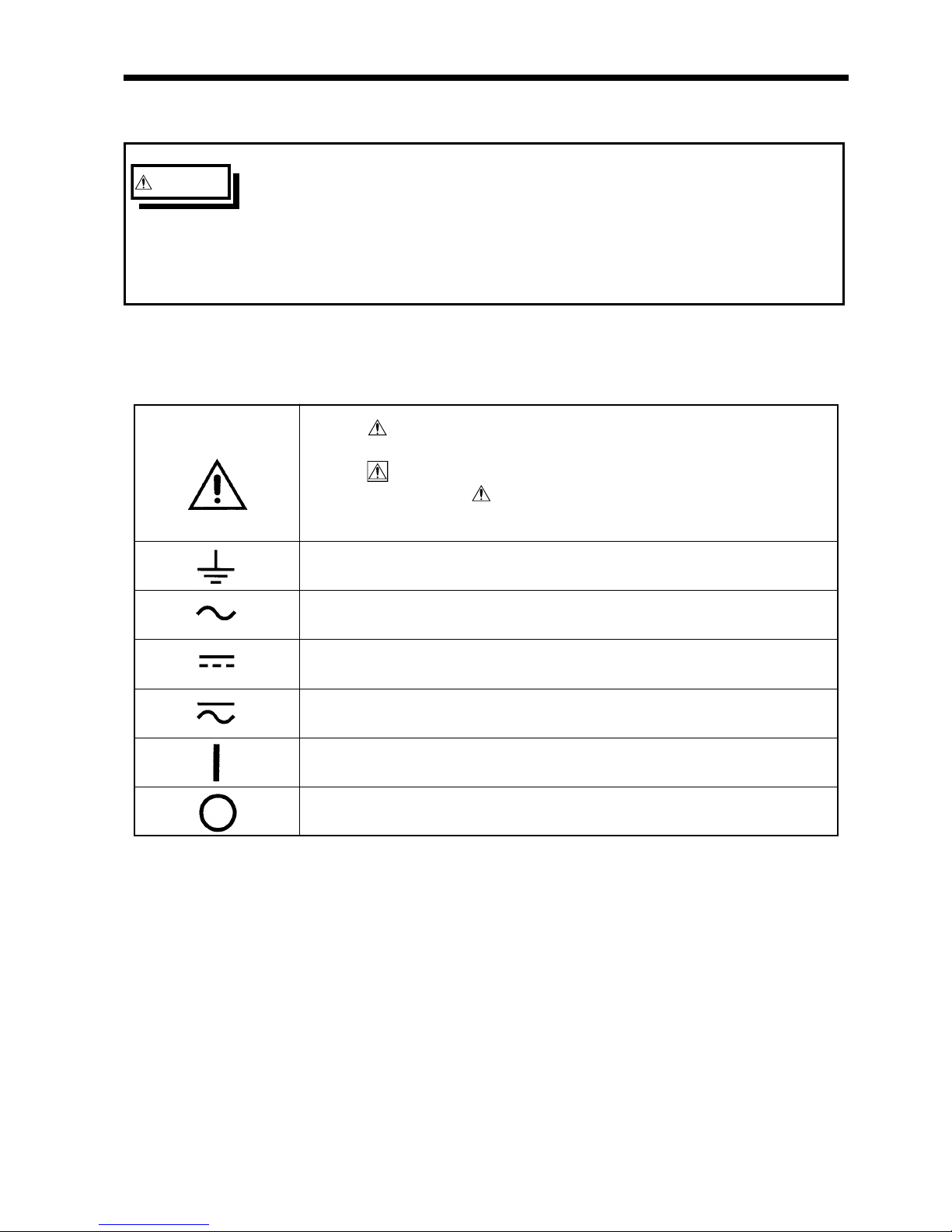
・The symbol printed on the instrument indicates that the user
should refer to a corresponding topic in the manual (marked with
the
symbol) before using the relevant function.
・In the manual, the
symbol indicates particularly important
information that the user should read before using the instrument.
Indicates a grounding terminal.
Indicates AC (Alternating Current).
Indicates DC (Direct Current).
Indicates both DC (Direct Current) and AC (Alternating Current).
Indicates the ON side of the power switch.
Indicates the OFF side of the power switch.
S
afety Notes
Safety symbols
This manual contains information and warnings essential for safe operation of
the instrument and for maintaining it in safe operating condition. Before
using the instrument, be sure to carefully read the following safety notes.
Accuracy
We define measurement tolerances in terms of f.s. (full scale) with the
following meanings:
f.s. (maximum display value or scale length)
The maximum displayable value or scale length. This is usually the name of
the currently selected range.
iv
────────────────────────────────────────────────────
Safety Notes
────────────────────────────────────────────────────
DANGE
R
Indicates that incorrect operation presents an extreme hazard that
could result in serious injury or death to the user.
WARNIN
G
Indicates that incorrect operation presents a significant hazard that
could result in serious injury or death to the user.
CAUTIO
N
Indicates that incorrect operation presents a possibility of injury to
the user or damage to the instrument.
NOTE
Advisory items related to performance or correct operation of the
instrument.
Conventions used in this manual
The following symbols in this manual indicate the relative importance of
cautions and warnings.
Measurement categories (Overvoltage categories)
This instrument complies with CAT safety requirements.
To ensure safe operation of measurement instruments, IEC 61010 establishes
safety standards for various electrical environments, categorized as CAT
to
CAT
, and called measurement categories. These are defined as follows.
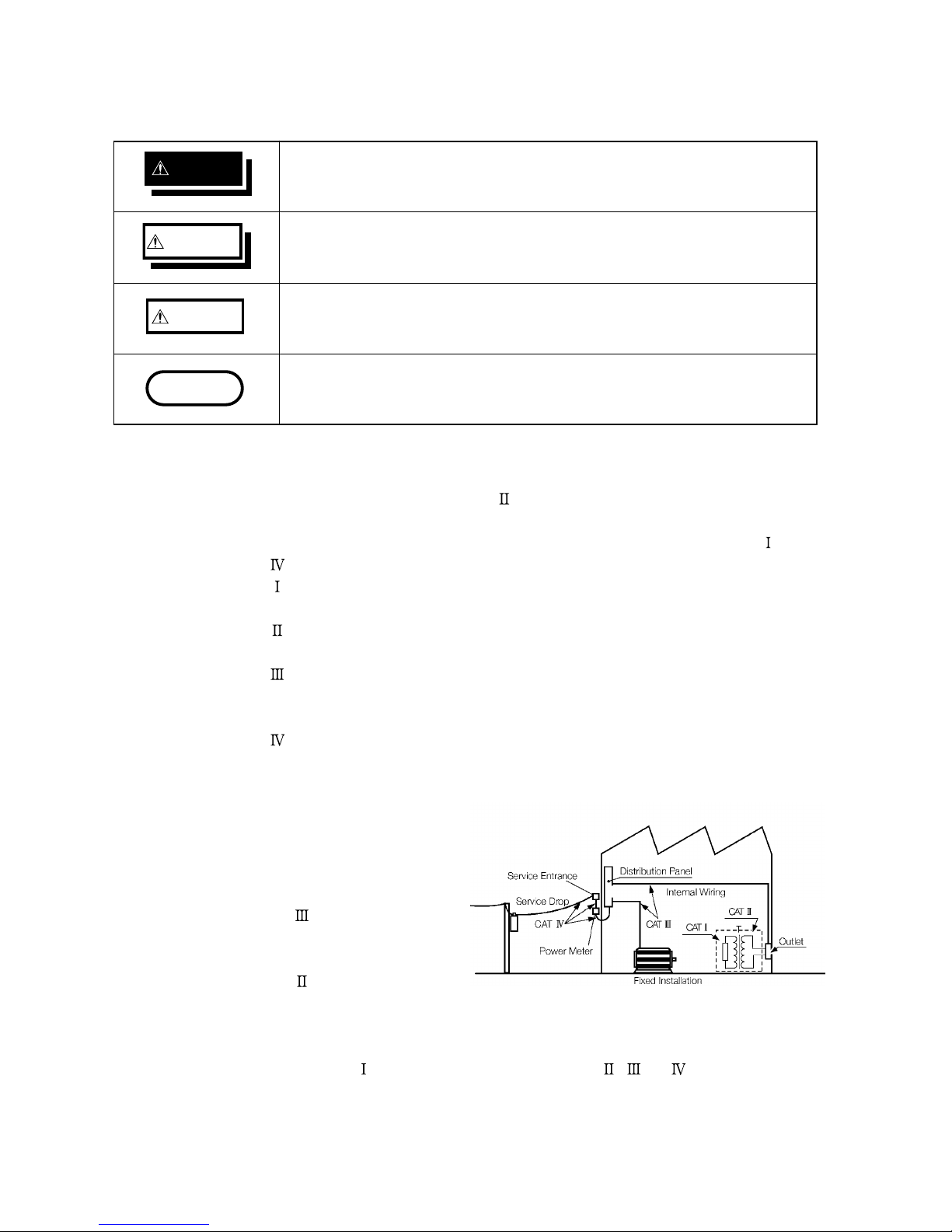
CAT
: Secondary electrical circuits connected to an AC electrical outlet through
a transformer or similar device.
CAT
: Primary electrical circuits in equipment connected to an AC electrical
outlet by a power cord (portable tools, household appliances, etc.)
CAT
: Primary electrical circuits of heavy equipment (fixed installations)
connected directly to the distribution panel, and feeders from the
distribution panel to outlets.
CAT
: The circuit from the service drop to the service entrance, and to the
power meter and primary overcurrent protection device (distribution
panel).
Higher-numbered categories
correspond to electrical
environments with greater
momentary energy. So a
measurement device designed
for CAT
environments can
endure greater momentary
energy than a device designed
for CAT
.
Using a measurement instrument in an environment designated with a highernumbered category than that for which the instrument is rated could result in a
severe accident, and must be carefully avoided.
Never use a CAT
measuring instrument in CAT , ,or environments.
The measurement categories comply with the Overvoltage Categories of the
IEC60664 Standards.
v
────────────────────────────────────────────────────
Notes on Use
────────────────────────────────────────────────────
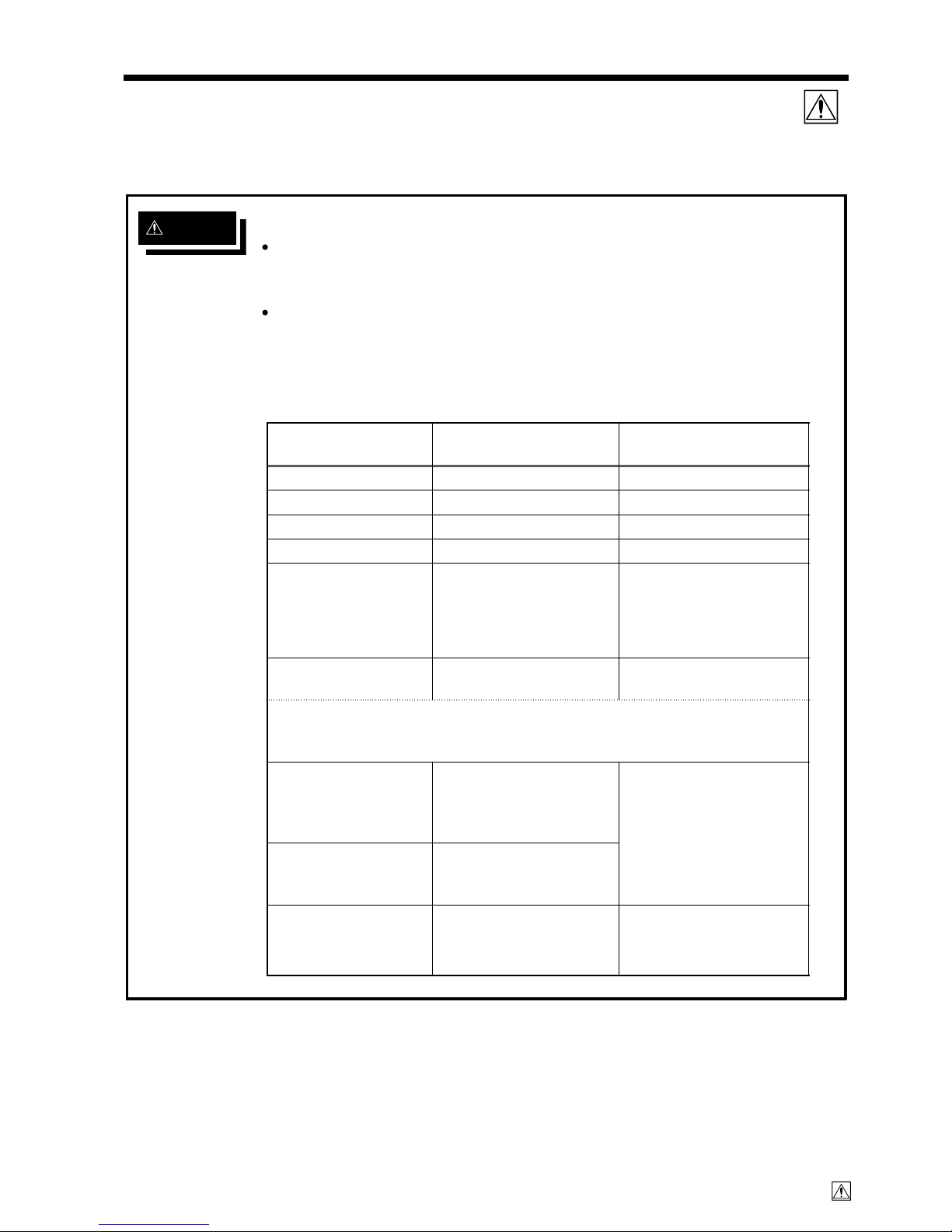
DANGE
R
■ Probe Connection, Measurement Voltage Input
Maximum input voltage ratings for the input units and the input
terminals of the 8826 are shown below. To avoid the risk of electric
shock and damage to the units, take care not to exceed these ratings.
The maximum rated voltage to earth of the input units (voltage between
input terminals and 8826 frame ground, and between inputs of other
analog units) is shown below. To avoid the risk of electric shock and
damage to the units, take care that voltage between channels and
between a channel and ground does not exceed these ratings.
Input/output terminalMaximum input voltage
Maximum rated voltage
to earth
8936 inputs 400 V DC max. 370 V AC/DC
8937 inputs 30 V rms or 60 V DC 30 V rms or 60 V DC
8938 inputs 400 V DC max. 370 V AC/DC
8939 inputs 10 V DC max. 30 V rms or 60 V DC
8940 inputs
30 V rms or 60 V DC
(BNC/Sensor
connector terminal)
・ 30 V rms or 60 V DC
(BNC terminal)
・ Not insulated
(Sensor connector
terminal)
8947 inputs 30 V rms or 60 V DC
(BNC terminal)
30 V rms or 60 V DC
(BNC terminal)
The maximum allowable charge that can be applied to the miniature
connection terminals is 500 pC at the most sensitive of the six ranges,
and 50,000 pC at the least sensitive range.
EXT TRIG
START・STOP
PRINT
EXT SMPL
-5 to +10 V DC
Not insulated
TRIG OUT
GO
NG
-20 V to +30 V DC
500 mA max.
200 mW max.
9322
DIFFERENTIAL
PROBE
2000 V DCmax.
1000 V ACmax.
1500 V AC/DC
(when using grabber clips)
1000 V AC/DC
(when using alligator clips)
N
otes on Use
Follow these precautions to ensure safe operation and to obtain the full
benefits of the various functions.

vi
────────────────────────────────────────────────────
Notes on Use
────────────────────────────────────────────────────
DANGE
R
The external I/O terminal and the unit have a common GND.
The maximum rated voltage to earth rating applies also if an input
attenuator or similar is used. Ensure that voltage does not exceed these
ratings.
When measuring power line voltages with the 8936 or 8938, always
connect the probe to the secondary side of the circuit breaker.
Connection to the primary side involves the risk of electric shock and
damage to the units.
Before using the instrument, make sure that the insulation on the
connection cords is undamaged and that no bare conductors are
improperly exposed. Using the instrument under such conditions could
result in electrocution. Replace the connection cords specified by Hioki.
■Logic Probe Connection
The logic input and 8826 Unit share a common ground. Therefore, if powe
r
is supplied to the measurement object of the logic probe and to the 8826
from different sources, an electric shock or damage to the equipment may
result. Even if power is supplied from the same system, if the wiring is such
that a potential difference is present between the grounds, current will flow
through the logic probe so that the measurement object and 8826 could be
damaged. We therefore recommend the following connection method to
avoid this kind of result. Refer to Section 2.5 for details.
(1) Before connecting the logic probe to the measurement object, be sure
that power is supplied from the same outlet box to the measuremen
t
object and the 8826 using the supplied grounded 2-wire power cord.
(2) Before connecting the logic probe to the measurement object, connec
t
the ground of the measurement object to the 8826 ground terminal. Also
in this case, power should be supplied from the same source. Refer to
Section 2.2 for grounding terminal details.
vii
────────────────────────────────────────────────────
Notes on Use
────────────────────────────────────────────────────
WARNIN
G
■ Replacing the input units
・ To avoid electric shock accident, before removing or replacing an input
module, confirm that the instrument is turned off and that the power
cord, connection cords, and thermocouples are disconnected.
・ To avoid the danger of electric shock, never operate the instrument with
an input module removed. To use the instrument after removing an
input module, install a blank panel over the opening of the removed
module.
■ Preliminary Checks
・ Before using the instrument the first time, verify that it operates
normally to ensure that the no damage occurred during storage or
shipping. If you find any damage, contact your dealer or Hioki
representative.
・ Before using the instrument, make sure that the insulation on the
connection cords is undamaged and that no bare conductors are
improperly exposed. Using the instrument under such conditions could
result in electrocution. Replace the connection cords specified by Hioki
.
■ Power supply connections
・ Before turning the instrument on, make sure the source voltage
matches that indicated on the instrument’s power connector.
Connection to an improper supply voltage may damage the instrument
and present an electrical hazard.
■ Grounding the unit
・ To avoid electric shock and ensure safe operation, connect the power
cable to a grounded (3-contact) outlet. (refer to Section 2.2).
■ Usage Precautions for the Internal MO Drive (option)
・ Please do not attempt to disassemble the MO drive.
・ Laser radiation can be emitted when the MO drive is open. Avoid
looking directly into the laser when the MO drive is open. Maximum
laser output is 50 mW (at 685 nm, pulsed).
A
laser warning label is attached to the bottom of the 8826 Uni
t.
R
efer to Section 1.2 for the label location.

viii
────────────────────────────────────────────────────
Notes on Use
────────────────────────────────────────────────────
CAUTIO
N
■ Installation environment
・ This instrument should be installed and operated indoors only, between 5 and
40℃ and 35 to 80% RH.
・ Do not store or use the instrument where it could be exposed to direct
sunlight, high temperature or humidity, or condensation. Under such
conditions, the instrument may be damaged and insulation may deteriorate
so that it no longer meets specifications.
・ To avoid electric shock, do not allow the instrument to get wet, and do not
use it when your hands are wet.
・ Do not use the instrument where it may be exposed to corrosive or
combustible gases. The instrument may be damaged or cause an explosion.
■ Before powering on
・ The microgap power switch construction necessitates that the instrument be
used near a power outlet. When not in use and while making connections to
the circuit to be tested, disconnect the instrument from the power source by
unplugging it from the outlet.
■
Using a connection cable
・ Use only the specified connection cord. Using a non-specified cable may
result in incorrect measurements due to poor connection or other reasons.
■
Storing
・ When the unit is not to be used for an extended period, set the head
up/down lever to the "head up" position. This will protect the printer head
and prevent deformation of the rubber roller.
■ Precautions on carrying this equipment
・ The terminal guard of the equipment protects the inputs. Do not hold this
guard when carrying the equipment. To carry this equipment, use the
handle. See section 1.2.
■
Shipping
・ Remove the printer paper from the unit. If the paper is left in the unit, paper
support parts may be damaged due to vibrations.
・ To avoid damage to the instrument, be sure to remove the floppy disk, MO
disk, PC card, and SCSI cable before shipping.

ix
────────────────────────────────────────────────────
Notes on Use
────────────────────────────────────────────────────
NOTE
■ Using a printer
・ Avoid using the printer in hot, humid environments, as this can greatly reduce
printer life.
■
Recording paper
・ This unit uses a thermal printer. The recording paper supplied has
characteristics finely tuned for use with the printer.
Using recording paper of a different specification may not only result in
impaired printing quality, but even prevent the printer from operating. Always
use the HIOKI specified instrument.
・ Printing is not possible if the recording paper is loaded wrong-side up. (See
Section 2.8)

x
────────────────────────────────────────────────────
Chapter Summary
────────────────────────────────────────────────────
Chapter 1
Product Overview
Contains an overview of the unit and its features.
Chapter 2
Installation and Preparation
Explains how to set the unit up for measurement.
Chapter 3
Basic Key Operation
Explains how to operate the keys and the JOG/SHUTTLE
control for carrying out basic measurement functions.
Chapter 4
Memory Recorder Function
Explains how to use the memory recorder functions of the unit.
Chapter 5
Recorder Function
Explains how to use the recorder functions of the unit.
Chapter 6
RMS Recorder Function
Explains how to use the RMS recorder functions of the unit.
Chapter 7
Recorder & Memory Function
Explains how to use the Recorder & Memory Functions of th
e
unit.
Chapter 8
FFT Function
Explains how to use the FFT recorder functions of the unit.
Chapter 9
Input Channel Settings
Explains how to make settings using the channel setting screen
.
Chapter 10
Trigger Functions
Explains how to use the trigger functions of the unit.
Chapter 11
Display Screen Operation
Explains how to perform waveform scrolling, how to use the
A/B cursors and so.
Chapter 12
System Screen Settings
Explains how to make settings using the system setting screen.
Chapter 13
Printout of Measurement Data
Explains how to print out measurement data and how to rea
d
printed charts.
Chapter 14
Storing Measurement Data
Explains how to store, recall, and delete measurement data an
d
measurement settings.
Chapter 15
Memory Segmentation Function
Explains how to use the Memory Segmentation Function.
C
hapter Summary

xi
────────────────────────────────────────────────────
Chapter Summary
────────────────────────────────────────────────────
Chapter 16
Waveform Operation Function
Explains how to use the Calculating, Waveform
Parameters/Evaluating Parameter value and Waveform GO/NG
Evaluation.
Chapter 17
External Input/Output Terminals
Gives specifications and usage details of the external
input/output terminals, and explains how to use the key lock
function.
Chapter 18
Specifications
Contains general specifications and detailed function
specifications.
Chapter 19
Logic and Analog Inputs
Contains specifications and precautions for logic input section
and input amplifier units.
Chapter 20
Maintenance and Service
Describes maintenance procedures.
Chapter 21
Appendix
Contains information that is necessary for using this unit,
including a description of error messages, a glossary, and an
explanation how to increase memory.

xii
────────────────────────────────────────────────────
Chapter Summary
────────────────────────────────────────────────────

1
────────────────────────────────────────────────────
────────────────────────────────────────────────────
1
2
3
4
5
6
7
8
9
10
11
12
13
14
A
Chapter
1
Product Overvie
w

2
────────────────────────────────────────────────────
1.1 Major Features
────────────────────────────────────────────────────
1
.1 Major Features
(1) Powerful waveform capture capability
・Using the analog unit 8936 (unbalanced), waveform recording can be
performed in up to 32 channels with 12-bit resolution.
(2) Easy to read, TFT color display
・The 10.4-inch TFT color screen with a resolution of 640 × 480 dots shows
all information at a glance.
(3) Five functions to meet a huge range of applications
・Memory recorder with up to 1 μs (all channels simultaneously) (1 MS/s)
・Real-time recording capability to paper in recorder function
・RMS recorder function for recording rms values of AC power supply lines
and DC sources.
・Recorder & Memory Recorder function provides combined recorder and
memory recorder functions
・FFT function offers 12 types of analysis functions
(4) Large capacity memory of max. 16 M words
・The memory is expandable up to 64 M words. (option)
(5) Flexible trigger function
・Digital trigger circuit
・Trigger types: level trigger, window-in trigger, window-out trigger, voltage
drop trigger, RMS level trigger, logic trigger
(6) Simple function key interface (GUI)
・Thanks to its GUI-inspired design using large function key graphics, the
unit is easy to set up and operate.
(7) On-line help
・On-line help guides the user through operation steps and various functions.
(8) Scaling function
・By setting the physical amount and the unit to be used for 1 V input, the
measurement result can be converted into any desired scale.
(9) Additional recording function
・When enabled, the memory is regarded as printer paper.
(10) Floating input units
・The analog inputs are floating, and so each input can be connected to its
own independent potentials.
(11) Built-in thermal printer
・Thermal line head
・The built-in printer delivers waveform printouts on the spot.
・The printer can also be used to print screen shots and parameter
information.
・Report print (B4 size) can be printed.

3
────────────────────────────────────────────────────
1.1 Major Features
────────────────────────────────────────────────────
1
2
3
4
5
6
7
8
9
10
11
12
13
14
A
(12) The floppy-disk drive, MO drive (option), and PC card can be used as external
storage means.
・The waveform data and/or setup conditions can be stored on a floppy disk,
MO disk, or PC card (SRAM, flash ATA, or HDD card).
(13) SCSI and PC card slots are originally equipped as external interfaces.
・If a MO drive is connected to the SCSI interface, the waveform data and/or
setup conditions can be stored on a MO disk.
・A GP-IB card, RS-232C card, 10BASE-T LAN card, and printer card can be
inserted into the PC card slot.
(14) GP-IB and RS-232C interface
・Remote control including input unit is possible.
(15) Color print
・If a color printer is connected to the printer card, the data can be printed in
color.
(16) Dual-language capability
・Display language is switchable between Japanese and English.
4
────────────────────────────────────────────────────
1.2 Names and Function of Parts
────────────────────────────────────────────────────
1 2 3 4 56 7 8 9 1
0111213141516181920
2
1
2
22324252627282930
3
13317
3
2
1
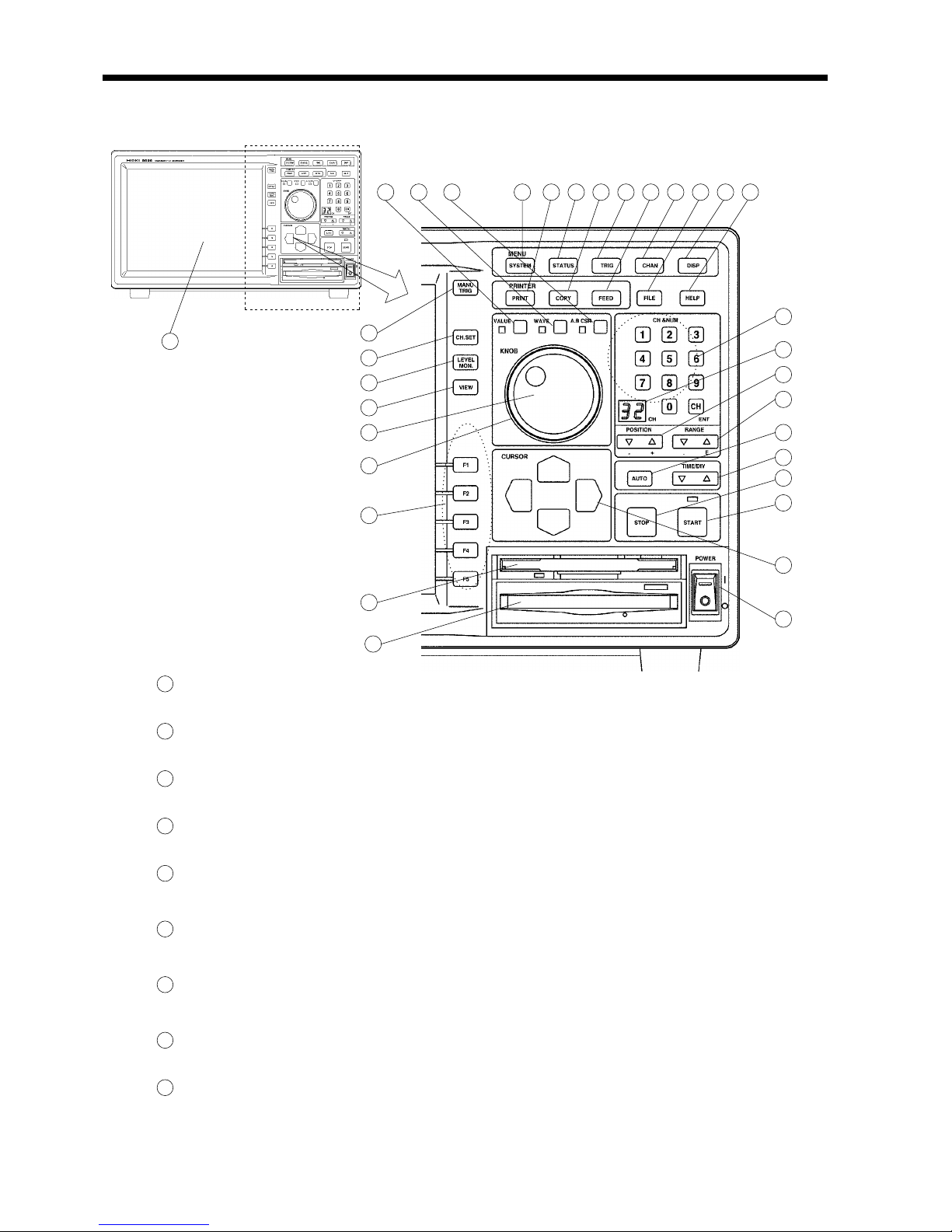
SYSTEM key
・ Causes the display to show the SYSTEM screen which serves for
making system-wide settings such as for the scaling function.
2
STATUS key
・ Causes the display to show the STATUS screen which serves for
setting most measurement parameters.
3
TRIG key
・ Causes the display to show the TRIGGER screen. Setting the
trigger functions.
4
CHAN key
・ Causes the display to show the CHANNEL screen which serves
for making input channel settings.
5
DISP key
・ Causes the display to show measurement and analysis results.
・ The display size can be change the normal size or wide size.
6
PRINT key
・ Serves to print out stored waveforms.
・ Output destination by the PRINT key set the SYSTEM4 screen.
7
COPY key
・ Serves to print out a hard copy of the current screen display.
・ Copy destination by the COPY key set the SYSTEM4 screen
8
FEED key
・ Causes the printer paper to advance for as long as the key is
pressed.
9
FILE key
・ Causes the display to show the FILE screen which serves for
reading, storing, etc. the waveform data etc.
1
.2 Names and Function of Parts
 Loading...