

Page 1
8423
Instruction Manual
MEMORY HiLOGGER
Mar. 2019 Revised edition 9
8423A981-09 19-03H
This manual describes the
Memory HiLogger's functions
and operation in detail, and its
specications.
EN
Page 2

Page 3

Contents
Introduction.................................................................................1
i
Contents
1
Verifying Package Contents .......................................................2
Safety Information ......................................................................4
Operating Precautions................................................................6
Chapter 1 Overview ________________________ 9
1.1 Product Overview ................................................................9
1.2 Features ............................................................................10
1.3 Names and Functions of Parts ..........................................12
1.4 System Configuration ........................................................ 15
1.5 Measurement Flowchart ...................................................16
Chapter 2 Installing the Software ____________ 17
2.1 Installing Logger Utility ......................................................18
2.2 Installing the USB Driver ...................................................21
2.3 Connect the instrument and computer with the USB
cable provided ...................................................................25
2
3
2.4 Starting and Ending Logger Utility ....................................28
2.5 Uninstalling the Logger Utility ...........................................30
Chapter 3 Setting Up the Instrument _________ 31
3.1 Attaching Units ..................................................................32
3.1.1 Unit Types ..............................................................................32
3.1.2 Attaching a Unit ......................................................................33
3.2 Connecting a Cable to the Terminal Block ........................ 35
3.2.1 Removing and Attaching a Terminal Block .............................35
3.2.2 Connecting a Cable ................................................................37
3.3 Installing the Memory HiLogger ........................................40
3.3.1 Mounting to a Wall Surface with Screws ................................40
3.3.2 Securing with a DIN Rail .........................................................41
3.4 Connecting the AC Adapter ..............................................42
3.5 Connecting a Communication Cable ................................43
3.5.1 Connecting the USB Cable .....................................................43
3.5.2 Connecting the LAN Cable .....................................................44
8423A981-09
3.6 Using a CF Card ............................................................... 45
Page 4

ii
Contents
3.6.1 Formatting a CF Card ............................................................ 45
3.6.2 Inserting and Ejecting a CF Card ........................................... 46
3.6.3 Replacing a CF Card during Measurement ........................... 47
3.6.4 File Protection during Power Outage ..................................... 47
3.7 Connecting Synchronization Cables ................................. 48
3.8 Connection Method for External Control Input Terminals . 50
3.9 Turning the Power On and Off .......................................... 52
Chapter 4 Software Screen _________________ 53
4.1 Main Screen ...................................................................... 53
4.2 Settings Screens ............................................................... 56
4.3 Display Settings Windows ................................................ 60
4.4 Channel Indication on Screens ......................................... 61
Chapter 5 Setting Measurement Conditions ___ 63
5.1 Registering Loggers in Logger Utility ................................ 64
5.1.1 Searching and Registering ..................................................... 64
5.1.2 Registering Manually ............................................................. 68
5.1.3 Settings for Synchronized Measurement ............................... 74
5.2 Confirming the Unit Configuration (Digital Filter Setting) .. 75
5.3 Configuring Basic Settings for Measurement ................... 77
5.3.1 Setting Function and Recording Interval ................................ 77
5.3.2 File Save Settings .................................................................. 82
5.3.3 Comment Input ...................................................................... 84
5.3.4 Recording Settings ................................................................ 85
5.4 Advanced Settings for Each Channel ............................... 89
5.4.1 Setting Measurement Conditions ........................................... 89
5.4.2 Waveform Calculation Settings .............................................. 96
5.4.3 Setting the Display Method .................................................... 98
5.4.4 Assigning Channels to Sheets ............................................. 103
5.5 Setting the Trigger Function ........................................... 105
5.5.1 Recording Operation during Simultaneous Use of Timer
Measurement and Triggers .................................................. 105
5.5.2 Pre-trigger ............................................................................ 109
5.5.3 Trigger Timing ...................................................................... 111
5.5.4 Trigger Sources ................................................................... 112
5.5.5 External Triggers .................................................................. 113
5.5.6 Analog Triggers ................................................................... 114
5.5.7 Logic Triggers ...................................................................... 117
5.6 Setting the Alarm Function ............................................. 118
Page 5

5.7 Setting Environment Conditions ......................................121
5.7.1 Setting External Control Input Terminals ..............................121
5.7.2 CF Card Save Settings .........................................................123
5.7.3 Time Value Display ...............................................................125
5.7.4 Start Backup .........................................................................126
5.8 Send Settings ..................................................................127
5.9 Process All ......................................................................128
iii
Contents
5.10 Narrowing Down of Display Channels ............................129
Chapter 6 Starting and Stopping Measurement131
6.1 Pre-Operation Inspection ................................................134
6.2 Starting and Ending Measurement .................................135
6.2.1 Computer Based Measurement ............................................135
6.2.2 Standalone Measurement ....................................................137
Chapter 7 Analyzing Measurement Data _____ 139
7.1 Changing the Waveform Display Range ......................... 140
7.2 Checking Cursor Values .................................................141
7.3 Changing Display Settings ..............................................142
7.3.1 Switching between Waveform Display and List Display .......142
7.3.2 Waveform Display Settings ..................................................143
7.3.3 List Display Settings .............................................................148
7.3.4 Common Settings and Auto Update Settings .......................149
3
4
5
6
7
8
7.4 Calculations ....................................................................150
7.4.1 Calculation Settings ..............................................................150
7.4.2 Numerical Calculation Expressions ......................................152
7.5 Event Mark Function .......................................................153
7.5.1 Adding a Mark (Event Mark) to a Waveform ........................153
7.5.2 Searching for and Editing Event Marks ................................154
7.6 Searching for the Maximum Value, Minimum Value,
and Variation ...................................................................155
7.7 Displaying the Channel List ............................................159
7.8 Confirming Measurement Conditions ..............................160
7.9 Monitor Display ...............................................................161
Chapter 8 Saving and Reading Data ________ 163
8.1 Saving and Reading Measurement Data ........................164
8.1.1 Saving Measurement Data as Text ......................................164
8.1.2 Converting Measurement Data to an Excel File ...................167
Page 6

iv
Contents
8.1.3 Reading Measurement Data ................................................ 169
8.2 Saving and Reading Setting Data ................................... 170
8.2.1 Saving Setting Data ............................................................. 170
8.2.2 Reading Setting Data ........................................................... 170
8.3 Automatically Transferring Measurement Data to Excel . 171
8.3.1 Real-Time Transfer Settings ................................................ 171
8.3.2 Real-Time Transfer Example ............................................... 172
8.4 Notes in Windows Vista /7 .............................................. 173
Chapter 9 Printing _______________________175
9.1 Setting the Printing Range .............................................. 176
9.2 Settings for Waveform Print Options .............................. 177
9.3 Settings for the Appendix ................................................ 179
9.4 Printer Settings/Printing .................................................. 179
9.5 Copy to Clipboard ........................................................... 180
9.6 Print Example .................................................................181
Chapter 10 Setting Method for Logger ______185
10.1 Setting Method ................................................................ 186
10.2 Synchronized Measurement ........................................... 187
10.3 Date ................................................................................ 188
10.4 Time ................................................................................ 189
10.5 DHCP .............................................................................. 190
10.6 IP Address ...................................................................... 191
10.7 Subnet Mask ................................................................... 192
10.8 Port Number ................................................................... 193
10.9 Gateway .......................................................................... 194
10.10 Display Language ........................................................... 196
10.11 Self Check ...................................................................... 197
10.11.1 ROM Check ........................................................................ 197
10.11.2 RAM Check ......................................................................... 198
10.11.3 BUS Check ......................................................................... 199
10.11.4 Key Check .......................................................................... 200
10.11.5 LED Check .......................................................................... 201
10.11.6 LCD Check ......................................................................... 202
10.12 Displaying Individual Version Information ...................... 203
10.12.1 ROM Version ...................................................................... 203
10.12.2 FPGA Version ..................................................................... 204
Page 7

10.12.3 MAC Address ......................................................................205
10.12.4 Serial No. .............................................................................206
10.13 Reading and Writing a Setting File ................................ 207
10.13.1 Writing a Setting File ...........................................................207
10.13.2 Reading a Setting File .........................................................208
Chapter 11 Communications (HTTP/FTP) ____ 209
11.1 Displaying the Main Page ...............................................209
11.2 Starting and Stopping Measurement ..............................210
11.3 Current Value Display .....................................................211
11.4 Acquiring Data from Memory ..........................................212
11.5 Data Acquisition using FTP .............................................213
v
Contents
Index
Chapter 12 Specifications_________________ 215
12.1 General Specifications ....................................................215
12.2 Application Software .......................................................219
12.3 Unit Specification ............................................................221
12.3.1 Model 8948 Voltage/Temp Unit ............................................221
12.3.2 Model 8949 Universal Unit ...................................................223
12.3.3 Model 8996 Digital/Pulse Unit ..............................................226
12.3.4 Model 8997 Alarm Unit .........................................................227
12.4 Dimension Diagrams ....................................................... 228
Chapter 13 Maintenance and Service _______ 231
13.1 Cleaning ..........................................................................231
13.2 Troubleshooting ..............................................................232
13.3 Initializing Settings (System Reset) ................................233
13.4 Zero-position Calibration (Zero Adjustment) ...................234
8
9
10
13.5 Industrial Waste ..............................................................235
Appendix________________________________ A 1
Appendix 1 Scan Timing ............................................................... A 1
Appendix 2 Version Update........................................................... A 2
Appendix 3 Error Display............................................................... A 3
Appendix 3.1 Application Software .................................................................. A 3
Appendix 3.2 8423 Memory HiLogger Main Unit ............................................. A 5
Appendix 4 Recording Intervals and Maximum Times for
Recording to CF Cards............................................... A 7
11
12
13
Appendix
Page 8

vi
Contents
Appendix 4.1 Model 9726 PC Card 128M ........................................................A 8
Appendix 4.2 Model 9727 PC Card 256M ......................................................A 10
Appendix 4.3 Model 9728 PC Card 512M ......................................................A 12
Appendix 4.4 Model 9729 PC Card 1G ..........................................................A 14
Index ________________________________Index 1
Page 9
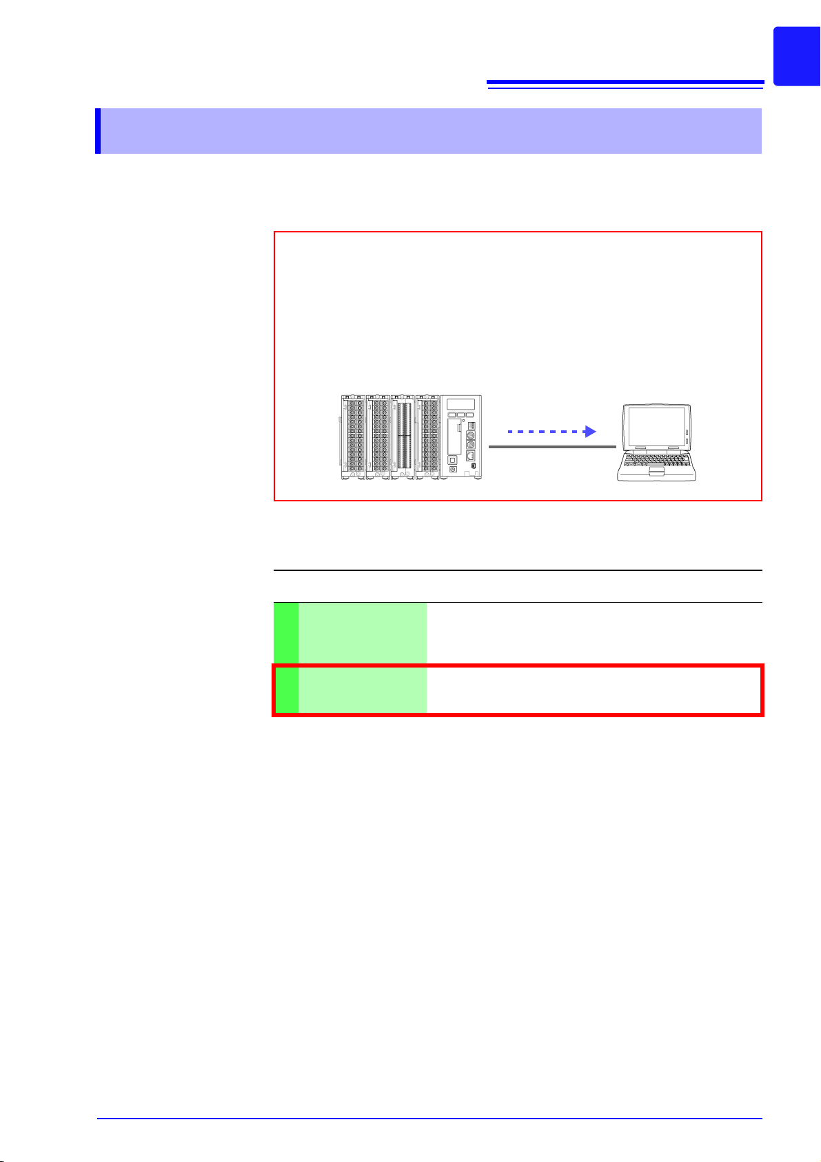
Introduction
The 8423 Memory HiLogger is a data collection instrument for use connected to a computer. This method of measurement is referred to as “computer based” within this manual. The supplied software Logger Utility is
used to set measurement conditions, start measurement, and otherwise
control the instrument. Install the software while referring to "Chapter 2
Installing the Software" (p. 17). You can also attach units to the instrument
in accordance with the measurement object. For details, refer to the manuals supplied with the units.
Measurement Data
USB or LAN
1
Introduction
Thank you for purchasing the HIOKI "Model 8423 Memory HiLogger." To obtain
maximum performance from the instrument, please read this manual first, and
keep it handy for future reference.
The following instruction manuals are included with the 8423 Memory HiLogger.
Refer to them as they pertain to your usage of the instrument.
Manuals Contents
Read first.
Quick Start Manual
1
Instruction Manual
2
(this manual)
Registered
Trademarks
• Windows, MS-DOS, and Excel is a registered trademark of Microsoft Corporation in the United States and/or other countries.
• Pentium is a registered trademark of Intel Corporation.
Offers an introduction to the 8423's basic measuring
method for first time users.
Contains explanation and instructions regarding the instrument's operating method and functions.
Page 10
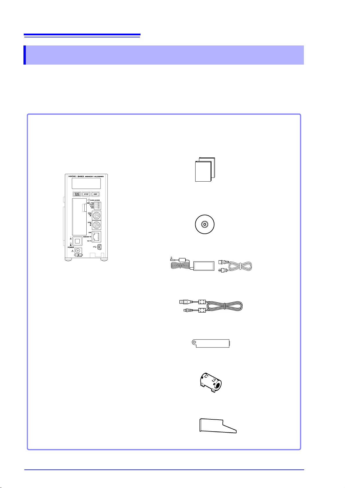
2
Model 8423 Memory HiLogger
.................................................. 1
Please check to make sure that no items are missing from your package.
Quick Start Manual ..................................1
Instruction Manual ...................................1
Logger Utility CD (data collection software)
.................................................................1
(The latest version can be downloaded from our web site.)
Model 9418-15 AC Adapter .....................1
USB Cable...............................................1
Connector Cover .....................................1
Ferrite Clamp...........................................1
Connection Plate .....................................1
Verifying Package Contents
Verifying Package Contents
When you receive the instrument, inspect it carefully to ensure that no damage
occurred during shipping. In particular, check the accessories, panel switches,
and connectors. If damage is evident, or if it fails to operate according to the
specifications, contact your dealer or Hioki representative.
Page 11

Verifying Package Contents
Options
The following options are available.
Model 8948 Voltage/Temp Unit Model 8949 Universal Unit Model 8996 Digital/Pulse Unit
3
Model 8997 Alarm Unit Model 9418-15 AC Adapter Model 9642 LAN Cable
Model 9683 Connection Cable (for
synchronization)
Model 9701 Humidity Sensor Model 9726 PC Card 128M
Model 9727 PC Card 256M
Model 9728 PC Card 512M
Model 9729 PC Card 1G
Page 12
4
Safety Information
Safety Information
This instrument is designed to comply with IEC 61010 Safety Standards,
and has been thoroughly tested for safety prior to shipment. However, mishandling during use could result in injury or death, as well as damage to
the instrument. Be certain that you understand the instructions and precautions in the manual before use. We disclaim any responsibility for accidents or injuries not resulting directly from instrument defects.
This manual contains information and warnings essential for safe operation of
the instrument and for maintaining it in safe operating condition. Before using it,
be sure to carefully read the following safety precautions.
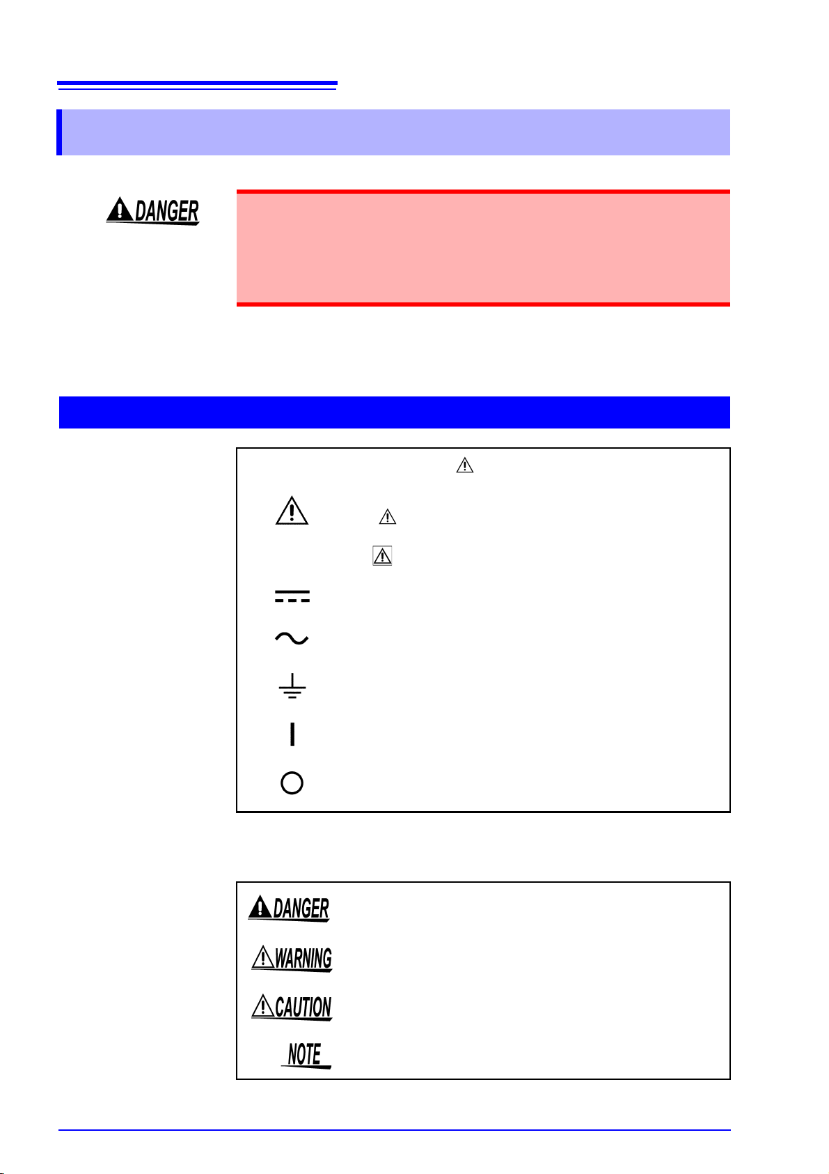
Safety Symbols
In the manual, the symbol indicates particularly important information that the user should read before using the instrument.
The symbol printed on the instrument indicates that the user
should refer to a corresponding topic in the manual (marked with
the symbol) before using the relevant function.
Indicates DC (Direct Current).
Indicates AC (Alternating Current).
Indicates a ground.
Indicates the ON side of the power switch.
Indicates the OFF side of the power switch.
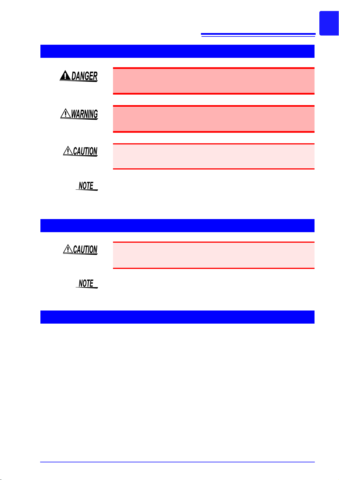
The following symbols in this manual indicate the relative importance of cautions
and warnings.
Indicates that incorrect operation presents an extreme hazard that
could result in serious injury or death to the user.
Indicates that incorrect operation presents a significant hazard that
could result in serious injury or death to the user.
Indicates that incorrect operation presents a possibility of injury to
the user or damage to the instrument.
Indicates advisory items related to performance or correct operation of the instrument.
Page 13

Notation
5
Safety Information
Indicates a prohibited action.
Indicates quick references for operation and remedies for troubleshooting.
*
Accuracy
We define measurement tolerances in terms of f.s. (full scale) with the following
meanings:
f.s. (maximum display value or scale length)
The maximum displayable value or scale length. This is usually the name of the
currently selected range.
Measurement Categories
This 8423's unit complies with CAT II safety requirements.
To ensure safe operation of measurement instruments, IEC 61010 establishes
safety standards for various electrical environments, categorized as CAT II to
CAT IV, and called measurement categories. These are defined as follows.
CAT II Primary electrical circuits in equipment connected to an AC elec-
CAT III Primary electrical circuits of heavy equipment (fixed installations)
Indicates that descriptive information is provided below.
trical outlet by a power cord (portable tools, household appliances, etc.)
CAT II covers directly measuring electrical outlet receptacles.
connected directly to the distribution panel, and feeders from the
distribution panel to outlets.
CAT IV The circuit from the service drop to the service entrance, and to
the power meter and primary overcurrent protection device (distribution panel).
Using a measurement instrument in an environment designated with a highernumbered category than that for which the instrument is rated could result in a
severe accident, and must be carefully avoided.
Use of a measurement instrument that is not CAT-rated in CAT II to CAT IV
measurement applications could result in a severe accident, and must be carefully avoided.
Page 14

6
Operating Precautions
Operating Precautions
Follow these precautions to ensure safe operation and to obtain the full benefits
of the various functions.
Preliminary Checks
Before using the instrument the first time, verify that it operates normally to
ensure that the no damage occurred during storage or shipping. If you find any
damage, contact your dealer or Hioki representative.
Before using the instrument, make sure that the insulation on the cables is
undamaged and that no bare conductors are improperly exposed. Using
the instrument in such conditions could cause an electric shock, so contact your dealer or Hioki representative for replacements.
Installing the Instrument
Operating temperature & humidity:
0 to 40°C (32 to 104°F), 30 to 80%RH (non-condensating)
Operating temperature & humidity for guaranteed accuracy:
23 ± 5°C (73 ± 9°F), 30 to 80%RH
Avoid the following locations that could cause an accident or damage to the
instrument.
Exposed to direct sunlight
Exposed to high temperature
Exposed to liquids
Exposed to high humidity or condensation
Exposed to high levels
of particulate dust
In the presence of corrosive or explosive
gases
Exposed to strong
electromagnetic fields
Near electromagnetic
radiators
Subject to vibration
Installing the
instrument
In addition to placing this instrument on a flat surface, you can also mount it on a
DIN rail or a wall surface.See "3.3 Installing the Memory HiLogger" (p. 40).
Page 15
Handling the Instrument
To avoid electric shock, do not remove the instrument's case. The internal
components of the instrument carry high voltages and may become very
hot during operation.
Never modify the instrument. Only Hioki service engineers should disassemble or repair the instrument. Failure to observe these precautions may
result in fire, electric shock, or injury.
To avoid damage to the instrument, protect it from physical shock when transporting and handling. Be especially careful to avoid physical shock from dropping.
7
Operating Precautions
Handling the Cables
Handling the CD
This instrument may cause interference if used in residential areas. Such use
must be avoided unless the user takes special measures to reduce electromagnetic emissions to prevent interference to the reception of radio and television
broadcasts.
• Avoid stepping on or pinching cables, which could damage the cable insula-
tion.
• To avoid breaking the cables, do not bend or pull them.
Use only the specified cables. Using a non-specified cable may result in incorrect measurements due to poor connection or other reasons.
Page 16

8
Operating Precautions
• Always hold the disc by the edges, so as not to make fingerprints on the disc or
scratch the printing.
• Never touch the recorded side of the disc. Do not place the disc directly on
anything hard.
• Do not wet the disc with volatile alcohol or water, as there is a possibility of the
label printing disappearing.
• To write on the disc label surface, use a spirit-based felt pen. Do not use a ballpoint pen or hard-tipped pen, because there is a danger of scratching the surface and corrupting the data. Do not use adhesive labels.
• Do not expose the disc directly to the sun's rays, or keep it in conditions of high
temperature or humidity, as there is a danger of warping, with consequent loss
of data.
• To remove dirt, dust, or fingerprints from the disc, wipe with a dry cloth, or use
a CD cleaner. Always wipe radially from the inside to the outside, and do no
wipe with circular movements. Never use abrasives or solvent cleaners.
• Hioki shall not be held liable for any problems with a computer system that
arises from the use of this CD, or for any problem related to the purchase of a
Hioki product.
Page 17

9
Data is transferred
in real time
USB or LAN
Computer Based Standalone
Data is saved to
a CF card
Start measurement
Stop measurement
Measurement is started and
stopped with the keys on
the instrument.
Optional 9683 Connection Cable
(for synchronization)
Maximum of
five loggers
Example of Connecting Multiple Memory HiLoggers
USB or LAN
HUB
1.1 Product Overview
1
Overview Chapter 1
1.1 Product Overview
The 8423 Memory HiLogger is a computer based data collection instrument. A
combination of four types of unit can be connected to enable the measurement
of up to 120 channels with one Memory HiLogger. Furthermore, the synchronous
operation of a maximum of five Memory HiLoggers enables you to build a system with up to 600 channels. The instrument transfers the measurement data to
the computer in real time. The instrument can also be used not just for computer
based data collection but also as a standalone instrument. (Measurement with
just this instrument is referred to as “standalone” within this manual.) In either
case, set the measurement conditions with the supplied software Logger Utility.
See "2.1 Installing Logger Utility" (p. 18).
Chapter 1 Overview
Page 18

10
1.2 Features
1.2 Features
10 ms Recording Intervals*
The fastest recording interval is 10 ms, during which the input data of all channels is scanned. The recording intervals can be set in 19 steps from 10 ms to 1
hour.
* The recording interval is 5 seconds or longer when one or more channels are
set to humidity measurement.
Multiple Channels (Up to 600 Channels)
A maximum of eight units can be connected to one 8423 Memory HiLogger to
enable the measurement of up to 120 channels. Furthermore, the synchronous
operation of five Memory HiLoggers facilitates the synchronized measurement of
600 channels.
Isolated Input Circuits
The input circuits of all of the channels are isolated*. The maximum rated voltage
to earth is 600 VAC/DC, so voltage can be measurement safely.
* 8948 Voltage/Temp Unit and 8949 Universal Unit only.
For the 8996 Digital/Pulse Unit, each 3 blocks of 5 channels are isolated within
the unit.
Dual Sampling
A combination of 2 types of recording interval can be set within the system. The
recording intervals can be set individually by unit. Measuring with a recording
interval suitable for each measurement object allows for efficient use of space in
the internal memory or CF card.
See "5.3.1 Setting Function and Recording Interval" (p. 77).
Flexible System Configuration
The following four types of unit can be used in accordance with the purpose of
use. The input terminal block is removable to enable connections to be made
easily.
• Model 8948 Voltage/Temp Unit and 8949 Universal Unit
There are 15 channel inputs per unit. Measurement is possible for voltage,
nine types of thermocouple, two types of resistance temperature detector*,
and humidity* (an optional sensor is required).
* Model 8949 Universal Unit only
• Model 8996 Digital/Pulse Unit
There are 15 channel inputs per unit. Logic input and pulse input can be set
for each channel. Logic signal, totalization, and rotation rate measurement are
possible.
• Model 8997 Alarm Unit
There are 15 channel outputs per unit. Alarm output (open collector output)
allows for controlling external devices.
Page 19

11
1.2 Features
Synchronized Measurement
Connecting multiple Memory HiLoggers with optional 9683 Connection Cable
(for synchronization) allows for synchronized measurement. See "3.7 Connecting Synchronization Cables" (p. 48).
Equipped with LAN & USB Interfaces
The instrument is compatible with LAN 100BASE-TX and USB2.0. A computer
and Memory HiLogger can be connected to enable the supplied software Logger
Utility to be used to control the Memory HiLogger and collect data.
Equipped with CF Card Slot
This allows you to save the setting conditions and the measurement data in real
time to a CF card. While data is being saved to the CF card in real time, you can
replace the CF card without stopping measurement. Furthermore, the risk of files
being damaged as a result of, for instance, an unexpected power outage is
greatly reduced because internal backup circuitry is used to process the ending
of files when there is a power outage.
Equipped with External Control Input Terminals
The Memory HiLogger can be controlled by inputting a signal from an external
device. This allows for the starting and stopping of measurement, external sampling, and external triggers.
1
Chapter 1 Overview
Standalone Measurement
After settings such as the measurement conditions have been configured from
Logger Utility, you can disconnect the computer and then start/stop measure-
ment with or on the instrument.
Page 20

12
CF card slot
Power switch
Front Panel
AC adapter connector
CF card access LED
External control input terminals
Synchronization cable connectors
100BASE-TX connector
USB connector
Display
Key operations
(See the next page)
1.3 Names and Functions of Parts
1.3 Names and Functions of Parts
Names of Parts Explanations
Display
CF card access LED
CF card slot Allows for a CF card to be inserted for saving measurement data.
Power switch Turns the power ON/OFF.
AC adapter connector Allows for a 9418-15 AC Adapter to be connected.
USB connector Allows for a USB cable to be connected.
100BASE-TX connector Allows for a 9642 LAN Cable to be connected.
Synchronization cable
connectors
External control input
terminals
Displays setting values, measurement values, error messages, warning
messages, and other information.
• When the cover is open:
Off: The CF card can be ejected.
Lit red: The CF card cannot be ejected because data is being written.
• When the cover is closed:
Off: A CF card is not inserted or recording is not possible because the
CF card cannot be recognized.
Lit green: A CF card is inserted and recording is possible.
Lit red: The CF card is being read or written.
Allows for connecting optional 9683 Connection Cable (for synchronization) when you want to perform synchronized measurement with multiple
Memory HiLoggers.
Allows for controlling the instrument by inputting a signal from an external
device.
Page 21
13
1.3 Names and Functions of Parts
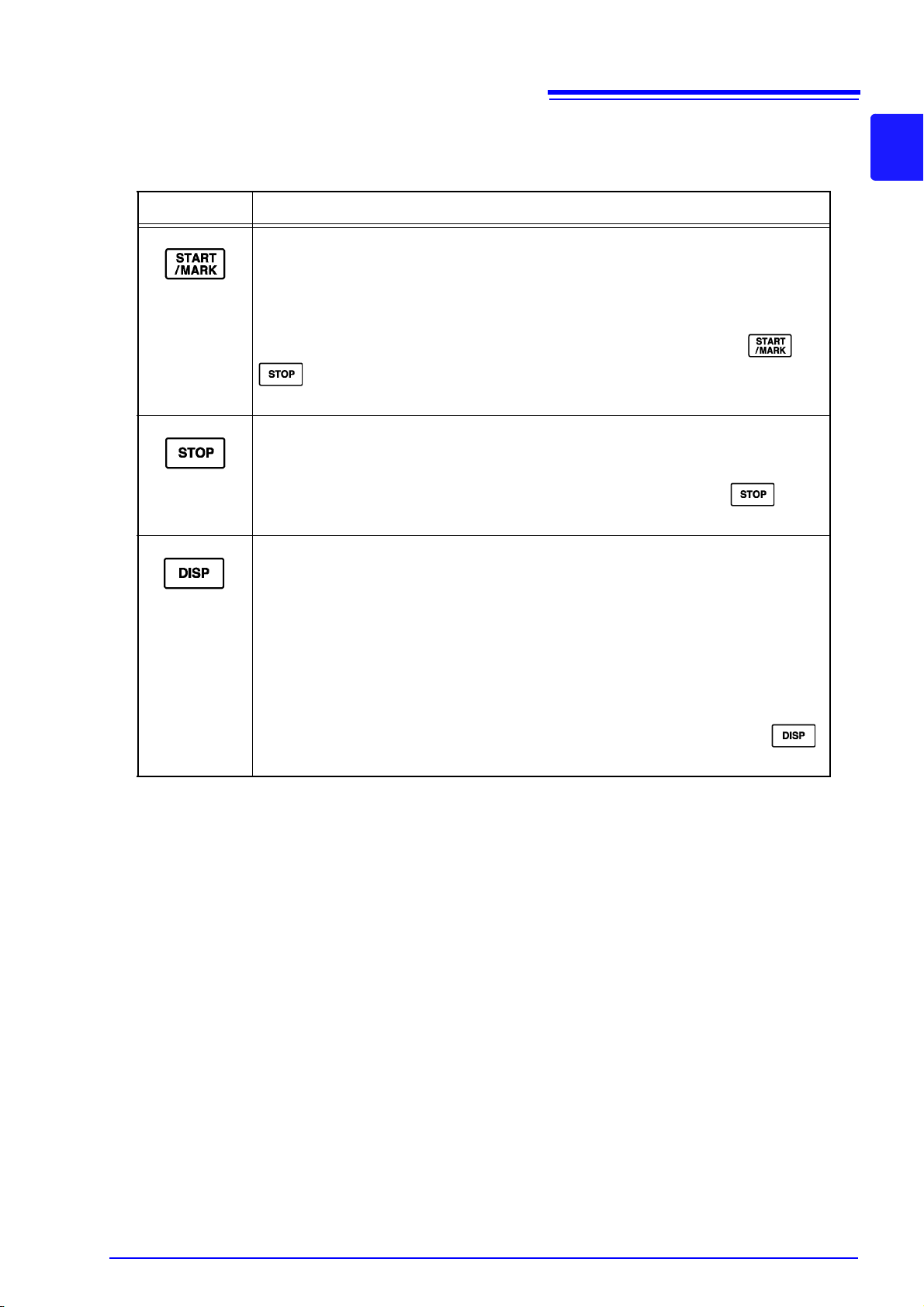
Key Operations
Keys Explanations
• The key lights during measurement.
• Press the key once during standby to start measurement.
• Press the key during measurement to input an event mark.
When the power is on:
You can initialize the settings by turning the power on while pressing and
See "13.3 Initializing Settings (System Reset)" (p. 233).
• Press the key twice in succession during measurement to stop measurement.
When the power is on:
You can initialize the settings by turning the power on while pressing .
See "13.3 Initializing Settings (System Reset)" (p. 233).
• Switches the display content.
• The key flashes while an error message or warning message is displayed. Press
• If the key is pressed for at least one second and then released while measure-
1
Chapter 1 Overview
.
the key once to clear the display.
ment values are displayed during measurement, the display channels are fixed
to those displayed the instant the key was released. Press the key for at least
one second again to cancel fixing of the display channels.
When the power is on:
The instrument enters setting mode if you turn on the power while pressing .
See "Chapter 10 Setting Method for Logger" (p. 185).
Page 22
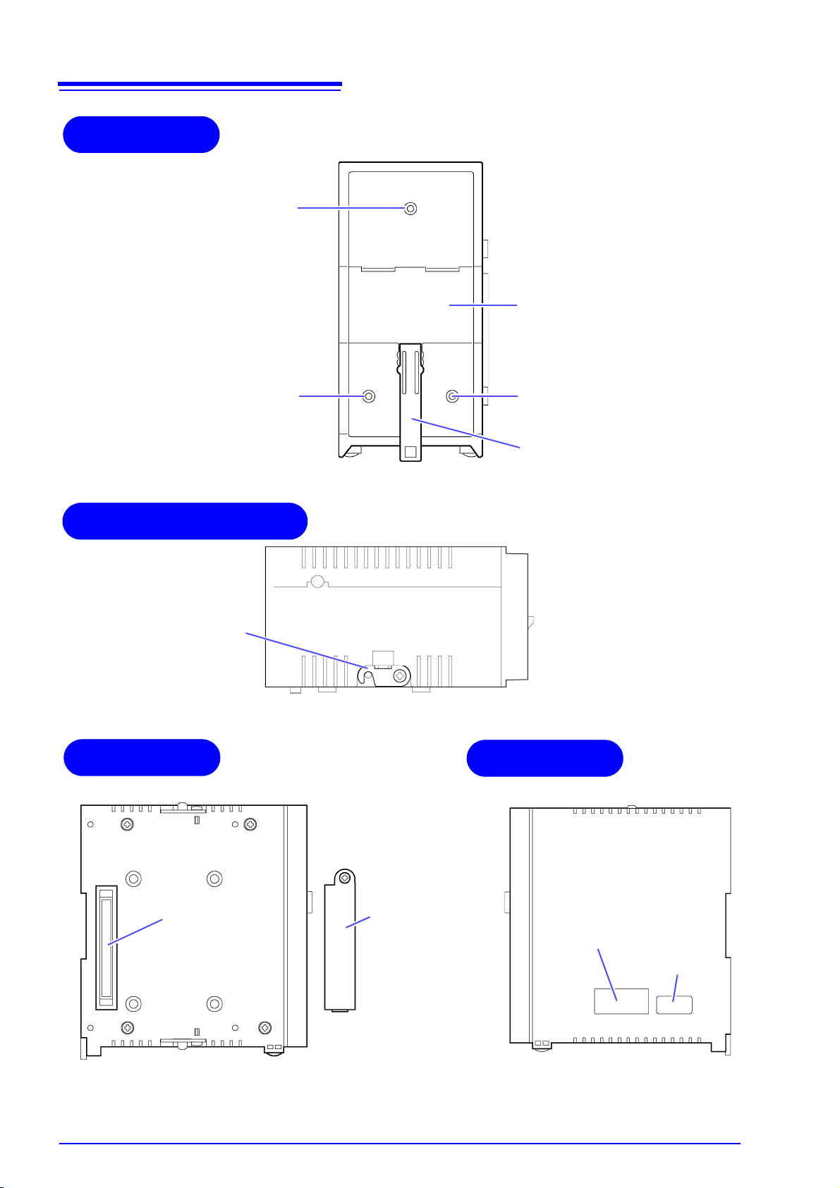
14
Rear Panel
Wall surface
mounting nut
Lever
DIN Rail Mounting Groove
Wall surface
mounting nut
Wall surface
mounting nut
Upper/Bottom Panel
Connection
fittings
Left Panel
Right Panel
Connector
Connector cover
Be sure to attach this to
the unit at the very end.
Serial No.
When controlling this instrument
with Logger Utility, use the serial
No. to differentiate it from other instruments.
MAC address
1.3 Names and Functions of Parts
Page 23

15
Model 9418-15 AC Adapter
Model 8423 Memory HiLogger
USB cable
Model 9683 Connection Cable (for
synchronization)
External control input
Model 8948 Voltage/Temp Unit
Model 8996 Digital/Pulse Unit
Model 8997 Alarm Unit
Model 8949 Universal Unit
Connection Example:
Model 9642 LAN
Cable
1.4 System Configuration
1.4 System Configuration
The system configuration is as follows.
1
Chapter 1 Overview
Page 24
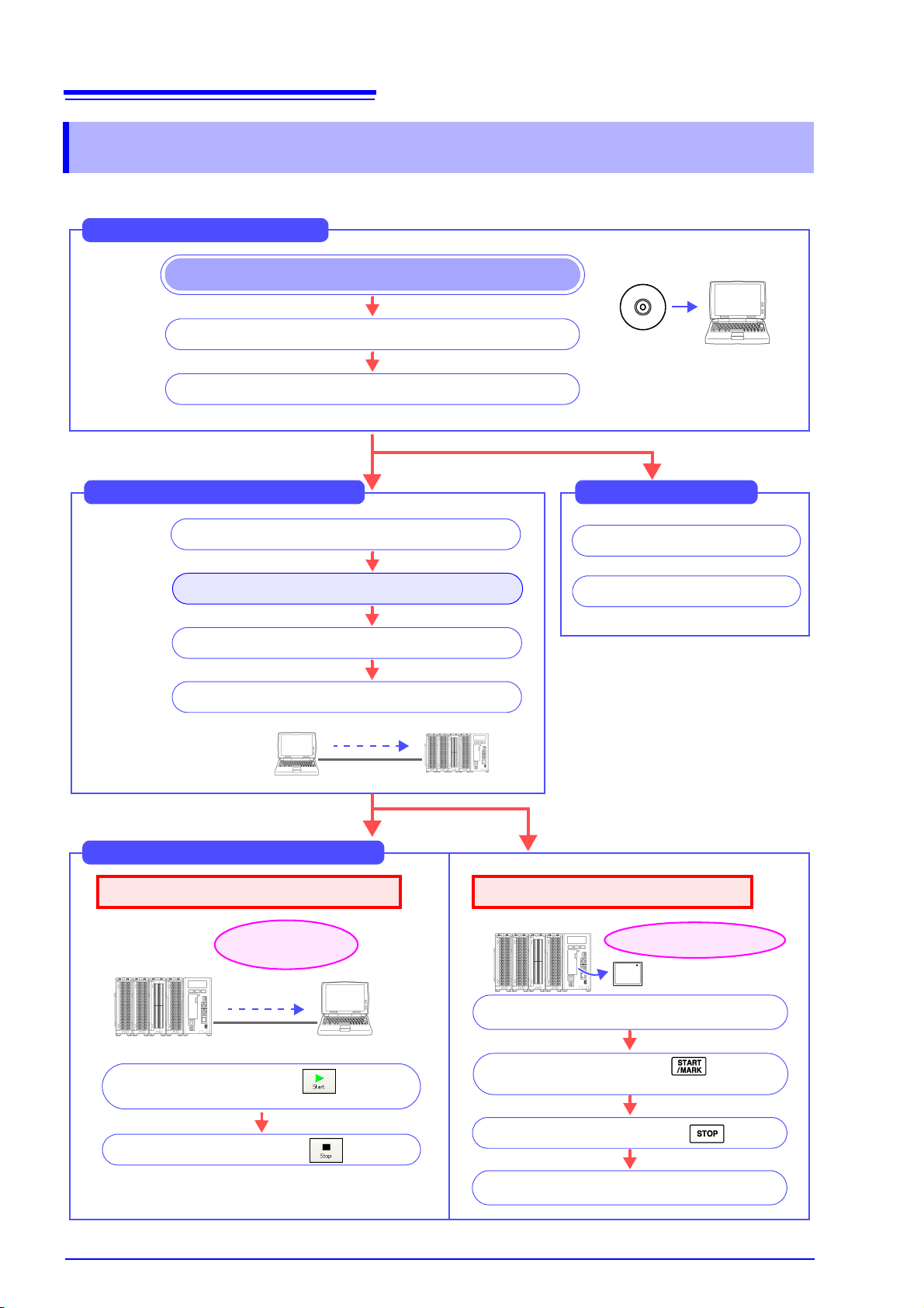
16
Save data to the CF card
Viewing Saved Data
Read the measurement data (p. 169)
Read the setting data (p. 170)
From Start to End of Measurement
At the time
of purchase
Preparing for Measurement
Start the software Logger Utility
Install and connect the instrument (p. 31)
Install the software on the PC (p. 18)
Disconnect the communication cable from the
instrument
Start measurement with the button of
Logger Utility
Start measurement with of the
Memory HiLogger
Stop measurement with the button
Stop measurement with
Setting Measurement Conditions
Register the logger in Logger Utility (p. 64)
Set the IP address and other communication settings
Set the measurement conditions (p.74 to p.126)
Send the settings to the instrument (p. 127)
For LAN
communication only
Load and display the measurement data
on the computer
Obtain and save data
in real time
Computer Based Measurement (p. 135)
Standalone Measurement (p. 137)
1.5 Measurement Flowchart
1.5 Measurement Flowchart
Proceed with measurement while referring to the following measurement flowchart.
Page 25
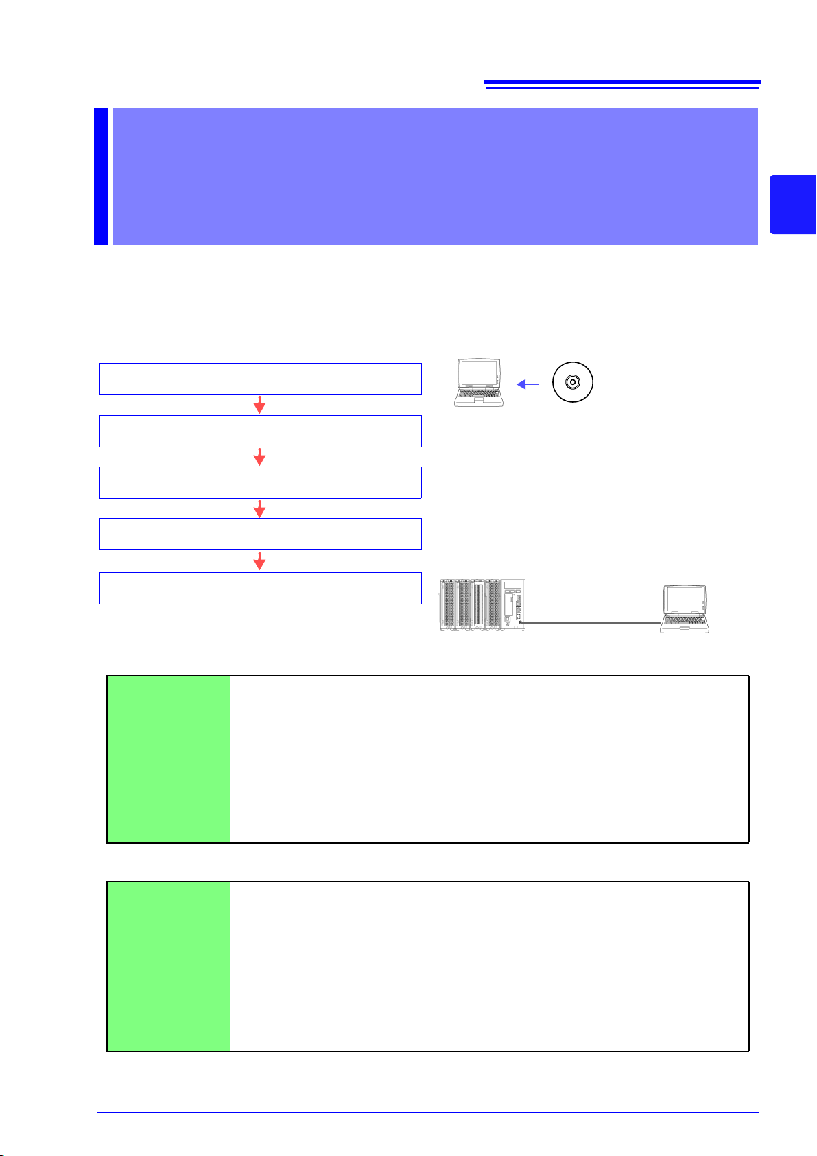
Installing the
(1) Set the CD into the drive of the computer
(2) Install Logger Utility (p. 18)
(5) Connect the instrument and computer with the USB
cable
Operating Environment
OS : Windows 2000 (with SP4 or later)
Windows XP (with SP2 or later)
Windows Vista
Windows 7
CPU : Pentium III (500 MHz) or better
Monitor Resolution : 1024 x 768 dots or better
Internet Explorer : 6.0 or better
Memory : At least 512 MB
Interface : Ethernet or USB
USB cable
Supplied CD
(4) Connect the AC adapter to the instrument and turn on
the power
(3) Install the USB driver (p. 21)
Software Chapter 2
Install the supplied software Logger Utility on the computer the first time you use
the instrument after purchase. Before starting the installation, check the operating environment.
Installation Procedure
17
2
Chapter 2 Installing the Software
Mouse Operation
Click Press and quickly release the left button of the mouse.
Right-click Press and quickly release the right button of the mouse.
Double click Quickly click the left button of the mouse twice.
Drag While holding down the left button of the mouse, move the mouse and then release
the left button to deposit the chosen item in the desired position.
Activate Click on a window on the screen to activate that window.
Notation
[ ]
CURSOR
(Bold characters)
Windows Unless otherwise specified, "Windows" represents Windows 2000, Windows XP,
Dialog Dialog box represents a Windows dialog box.
Menus, pages, setting items, dialogs, buttons in a dialog, and other names on the
screen and the keys are indicated in brackets.
Bold characters within the text indicate operating key labels.
Windows Vista or Windows 7.
Page 26

18
Important
If you are running software such as antivirus software, be sure to end
the software before you start the installation. The installation may not
be performed properly if antivirus software is running.
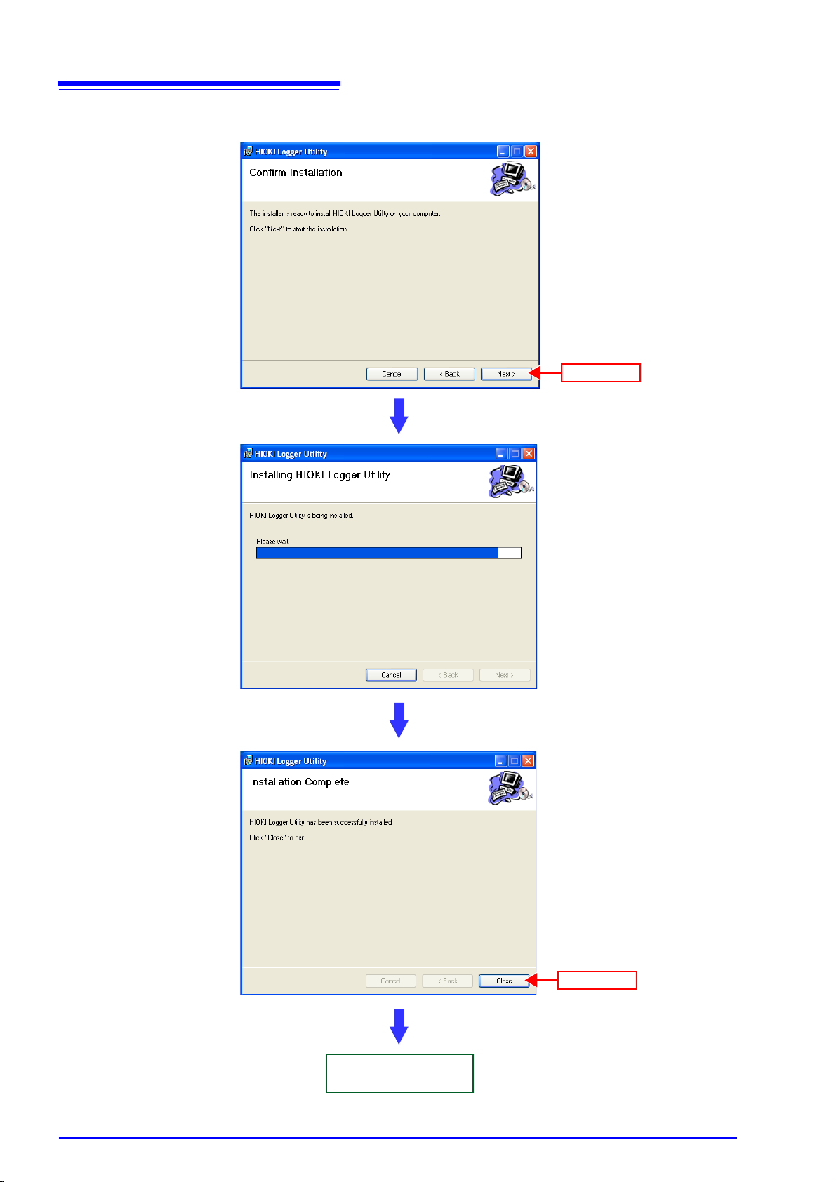
Click
2.1 Installing Logger Utility
2.1 Installing Logger Utility
Follow the procedure below to install Logger Utility. This explanation is for installing the software on Windows XP. The messages displayed may differ slightly
depending on other operation system or settings you are using.
1. Start up Windows.
Exit all running applications.
2. Insert the included CD into the computer's CD-ROM drive, the installer run
automatically.
If the installer do not start, execute “Setup.exe” from the CD-ROM drive.
In Vista, Although the dialog which ask for installation permission of application,
click
[Allow].
Page 27

19
(2) Click
(3) Click
(1) Click
(1) Click
(2) Click
To change the
installation destination
Click [Browse] to select another folder.
There is normally no need to
change it.
2.1 Installing Logger Utility
3. Click the [Next] button of the installer, then read and agree with the con-
tents in the License Agreement before clicking the [Next] button.
2
Chapter 2 Installing the Software
4. Click [Everyone] before clicking the [Next] button.
Page 28
20
Installation starts.
Progress is displayed during
installation.
To interrupt installation in
progress,
click
[Cancel].
Installation finished
(1) Click
(2) Click
2.1 Installing Logger Utility
5. Click [Next] to start installing.
Page 29

2.2 Installing the USB Driver
Click
Install the USB driver before you use the instrument with a USB connection.
1. Install the driver.
Run [SetupDriver32.msi] in the CD-R.
If [Logger Utility] is already installed, run the CD from the following location.
[c:\Program Files\HIOKI\LoggerUtility\Driver\SetupDriver32.msi]
If you are using the WindowsVista/7 64bit version:
[c:\Program Files(x86)\HIOKI\LoggerUtility\Driver\SetupDriver64.msi]
Run [SetupDriver64.msi] in the CD-R.
If [Logger Utility] is already installed, run the CD from the following location.
[c:\Program Files\HIOKI\LoggerUtility\Driver\SetupDriver64.msi]
21
2.2 Installing the USB Driver
2
Chapter 2 Installing the Software
Depending on the environment, the dialog box may take some time to appear so
please wait till it does so.
2. Click [Next].
Page 30

22
(2) Click
(1) Check
Click
2.2 Installing the USB Driver
3. Check [Everyone] and click [Next].
When you want to change the installation destination, click [Browse…] to change
the folder to install into. Normally, there is no need to change.
4. Click [Next] to start installing.
Installing.
Page 31

For WindowsXP
Click
Click
(1) Check
(2) Click
For Windows Vista/7
23
2.2 Installing the USB Driver
During the installation, a message saying that the software has not passed
Windows Logo testing will appear a few times, click [Continue Anyway]
continue installing.
When a dialog box requesting your permission to continue the program
appears, click [Continue].
to
2
Chapter 2 Installing the Software
Sometimes another dialog box requesting your permission to install the
software may appear. When it does, check [Always trust software from
“HIOKI E.E. CORPORATION”] and click [Install] to continue.
Page 32

24
Click
2.2 Installing the USB Driver
5. When installation is completed and the dialog box appears, click [Close] to
exit.
This completes the driver installation.
Page 33

25
(2) Click
(1) Check
2.3 Connect the instrument and computer with the USB cable provided
2.3 Connect the instrument and computer with
the USB cable provided
Please connect the instrument after installing the USB driver.
Do not plug in or unplug the USB cable while the instrument is operating.
For Windows 2000/Vista/7
1. Connect the AC adapter to the instrument and switch on the power.
2. Connect the instrument and computer with the USB cable provided.
The HiLogger is automatically recognized, and preparations to use the
device are complete.
For Windows XP
2
Chapter 2 Installing the Software
1. Connect the AC adapter to the instrument and switch on the power.
2. Connect the instrument and computer with the USB cable provided.
A [Found New Hardware Wizard] dialog box will appear and the new hardware detection wizard will begin.
3. Check [No, not this time] and click [Next].
Page 34

26
(2) Click
(1) Check
Click
2.3 Connect the instrument and computer with the USB cable provided
4. Check [Install the software automatically (Recommended)] and click
[Next].
Please wait while the driver is being installed.
5. A message saying that the software has not passed Windows Logo testing
will appear a few times, click [Continue Anyway] to continue installing.
Page 35

27
Click
2.3 Connect the instrument and computer with the USB cable provided
6. When installation is completed and the dialog box appears, click [Finish]
to exit.
2
Chapter 2 Installing the Software
This completes the driver installation.
Page 36

28
(1) Click
(2) Click
Click
2.4 Starting and Ending Logger Utility
2.4 Starting and Ending Logger Utility
Starting Logger Utility
From the Start Menu of Windows, click [All Programs] - [HIOKI] - [Logger Utility] -
[Logger Utility]
.
Logger Utility starts with the settings in the same state as when the software was
last ended. When you want to initialize the settings, click
from the File menu.
[Initialize All Settings]
Page 37

Ending Logger Utility
Click
Minimizes the
window.
Closes the
window.
Maximizes the
window size.
Close button
Click
Click [Exit Application] from the File menu of the main screen.
29
2.4 Starting and Ending Logger Utility
2
Chapter 2 Installing the Software
Alternatively, you can click the
screen.
[x] close button at the top right of the main
Page 38

30
The [Add or Remove Programs] screen
appears.
(1) Click
(3) Click
(2) Click
A confirmation dialog appears when
you click [Remove].
The uninstall process begins.
The uninstall progress status is displayed.
Uninstall is finished
(2) Click
(1) Click
2.5 Uninstalling the Logger Utility
2.5 Uninstalling the Logger Utility
Use the following procedure to uninstall the program.
1. From the Windows Start menu, select the [Control Panel], and double click
[Add or Remove Programs].
2. From the list of installed programs, select [HIOKI Logger Utility], and
remove it.
You are returned to the
Settings files are not deleted during uninstall, so if no longer needed, delete
them manually.
[Add or Remove Programs] screen.
Page 39

Setting Up
(1) Attaching units (p. 32)
(2) Connect the input cables to the units (p. 35)
(3) Installing the Memory HiLogger (p. 40)
(4) Connecting the AC adapter (p. 42)
(5) Connecting a communication cable (p. 43)
(6) Inserting a CF card (p. 46)
(7) Connecting synchronization cables (p. 48)
(8) Connect the cables to the external control input terminals (p. 50)
(9) Turning the power on (p. 52)
When performing
synchronized
measurement
When performing
external control
the Instrument Chapter 3
This section describes preparations for starting measurement.
Before connecting the instrument to a computer or network, install Logger Utility
while referring to "Chapter 2 Installing the Software" (p. 17).
Installation and Connection Procedure
31
3
Chapter 3 Setting Up the Instrument
7
Page 40

32
Measurement object
•Voltage
• Temperature (Thermocouple)
M3 screw terminal block
15 input channels
CH1
CH15
Measurement object
•Voltage
• Temperature
(Thermocouple/resistance
temperature detector)
• Humidity (use the 9701
Humidity Sensor)
Push-type terminal block
15 input channels
CH1
CH15
Measurement object
• Logic signal
• Pulse signal
• Rotation rate
M3 screw terminal block
15 input channels
CH1
CH15
Alarm output function
M3 screw terminal block
15 output channels
CH1
CH15
3.1 Attaching Units
3.1 Attaching Units
You can attach optional units to the instrument in accordance with the measurement object. A maximum of eight units (total of 120 channels) can be connected
to one instrument.
3.1.1 Unit Types
The following four types of unit are available. Select a unit in accordance with the
measuring object. For detailed specifications of the units, see "12.3 Unit Specification" (p. 221).
Unit List
Model 8948 Voltage/Temp Unit Model 8949 Universal Unit
This unit is capable of measuring voltage and temperature.
Model 8996 Digital/Pulse Unit Model 8997 Alarm Unit
This unit is capable of measuring pulse signals and
logic signals. It allows you to totalize the number of
pulses of, for instance, an integrating wattmeter or
flowmeter, and count the number of pulses of, for
instance, a rotation meter to obtain the rotation rate.
This unit is capable of measuring voltage, temperature, and humidity.
This unit outputs an alarm when the measurement
value satisfies the set alarm condition (output format:
open collector). This enables control of an external
device in accordance with an alarm.
Page 41

3.1.2 Attaching a Unit
Align
Left side of Memory
HiLogger
Right side of
unit
Press
Press
Maximum of eight units
(2) Press and turn
Top of the 8423
(1) Loosen the screw
(3) Tighten the screw
Connection
Fittings
This section describes attaching a unit to the instrument. Units are coupled
together with connectors on the left and right sides.
• To avoid electric shock accident, before removing or replacing a unit, confirm
that the instrument is turned off and that the cables are disconnected.
• If the units are not securely attached with the connection fittings, the specifications may not be satisfied, resulting in a malfunction.
• Failure to fasten the connectors properly may result is sub-specification performance or damage to the equipment
• Be sure to attach the supplied connector cover to the unit at the very end.
Up to eight units can be connected to the instrument. If nine or more units are
connected, measurement will not be possible.
33
3.1 Attaching Units
3
Chapter 3 Setting Up the Instrument
Required tools: Phillips screwdriver ................... 1
1. Turn off the power of the unit.
Disconnect any connected cables.
2. Attach the unit to the 8423 Memory HiLogger. To attach multiple units.
repeat the same procedure.
3. Secure the unit in place with the connection fittings at the top and bottom
of the unit.
Use the Phillips screwdriver to tighten the screws to no more than 0.6 Nm.
7
Page 42

34
Connector cover
DIN Rail Mounting Groove
Lever
3.1 Attaching Units
4. Attach the supplied connector cover to the unit on the very left side when
looking from the front.
Insert the protruding part of the connector cover into the connector opening of
the unit, close the cover, and then secure it in place with the screw. Tighten the
screw to no more than 0.6 Nm.
5. Pull down the levers on the rear of the instrument and unit, and hook the
connection plate on to the hooks at the top of the DIN rail mounting
groove.
6. Push up the levers until they click into place.
• When you remove the connection plate from the instrument, perform the
attachment procedure in the reverse order.
• When you secure the instrument to a wall surface or DIN rail, the connection
plate does not need to be attached.
Page 43

3.2 Connecting a Cable to the Terminal Block
Phillips screwdriver
Terminal block
3.2 Connecting a Cable to the Terminal Block
Connect cables to the terminal block of a unit in accordance with the purpose of
use.
3.2.1 Removing and Attaching a Terminal Block
A terminal block can be removed to enable the cable to be easily connected.
(You can also connect the cable while the terminal block is attached.)
To avoid an electric shock or short-circuit accident:
• Turn off the power of the instrument before removing and attaching the terminal block.
• Never attach or remove the terminal block while the power of a measurement
object to which a cable is connected is on.
35
3
Chapter 3 Setting Up the Instrument
1. Turn off the power of the unit.
Disconnect any connected cables.
2. Loosen the screws at the top and bottom of the unit with the Phillips
screwdriver, and pull the front to remove the terminal block.
3. Connect the cable, and then attach the terminal block by performing the
procedure up to now in the reverse order.
Tighten the screws to no more than 0.6 Nm.
7
Page 44

36
Mark area
Serial No.
Mark area
Front of unit
Front of terminal
block
3.2 Connecting a Cable to the Terminal Block
• Be sure to attach the removed terminal block to the unit to which it was originally attached.
• Since the structure of a terminal block is designed so that it cannot be attached
to a unit of a different type, using excessive force to try to attach a terminal
block to the wrong unit will damage the connector.
When you want to mark a terminal block and unit:
Use the mark area on the front of the unit for writing a number, comment, or
other information. If you use a pencil, you can erase the writing by just gently
wiping it off. It is convenient to mark the removed terminal blocks and the units
to help you remember which block to attach to which unit.
Page 45

3.2.2 Connecting a Cable
Lift up
Phillips screwdriver
+
-
Example:
Model 8948 Voltage/Temp Unit
CH1
CH15
To connect a cable to a terminal block, lift up the cover at the front and then connect the cable to the terminal block.
• In order to prevent electric shock and short-circuit accidents, shut off the power
to the line to be measured before connecting the input cable.
• To avoid electrical accidents, confirm that all connections are secure. The
increased resistance of loose connections can lead to overheating and fire.
• Channels are isolated by semiconductor relays. Never apply a voltage in
excess of the specifications between channels as doing so could damage the
semiconductor relays by causing them to short out. Exercise particular care
concerning surge protection against lightning and other threats. If the instrument yields erroneous measured values, have it inspected.
Be sure to pull out an input cable after you loosen the screws of the terminal
block. The input cable will be damaged if the screws are not loosened and
excessive force is used to pull out the input cable.
37
3.2 Connecting a Cable to the Terminal Block
3
Chapter 3 Setting Up the Instrument
1. Loosen the screw at the bottom of the cover with the Phillips screwdriver
and lift up the cover.
2. Loosen the screws of the terminal block, connect the input cable, and then
tighten the screws.
The connection method differs depending on the measurement object. See the
next page.
7
3. Reattach the cover, and tighten the screw.
Tighten the screw to no more than 0.6 Nm.
Page 46

38
+
-
Not connected
Model 8948 Voltage/Temp Unit
Model 8949 Universal Unit
Voltage Measurement and Temperature Measurement with Thermocouple
+
-
Not connected
Model 8948 Voltage/Temp Unit
Model 8949 Universal Unit
250 Ω shunt
resistance
250 Ω shunt
resistance
4-20 mA Input
Model 8949 Universal Unit
Black
Green
Yellow
Red
Model 9701 Humidity Sensor
Humidity Measurement
(3-wire)
Model 8949 Universal Unit
B
B
A
Not connected
(4-wire)
Model 8949 Universal Unit
B
B
A
A
Temperature Measurement with Resistance Temperature Detector
Model 8996 Digital/Pulse Unit
Model 8997 Alarm Unit
+
-
+
-
Logic Signal, Pulse, and Rotation Rate Measurement
Alarm Output
3.2 Connecting a Cable to the Terminal Block
See For more information about individual units' circuit architecture, see the circuit schematic for the unit in question.
(p. 133)
Page 47

39
6 mm
or less
6 mm
or less
Single strand
Multi-strand
5 mm
3.2 Connecting a Cable to the Terminal Block
• If an input cable of 3 m or longer is connected, measurement may be affected
by external noise and other electromagnetic interference.
• The general guidelines for resistance temperature detector terminations are pro-
vided in JIS Z 8704, in which A and B signals are designated by red and white
wires, respectively. However, the three-wire IEC guidelines define the connections differently (red and white are reversed), so special attention is required.
• The measurement current for a resistance temperature detector is 1 mA.
• Connect the cable while it is disconnected from the power line and ground wire.
• Be sure to close the terminal block cover, and tighten the screw.
• If the cable is connected in parallel with another device, there may be variations in the measurement values. When connecting in parallel, confirm operation before use.
• In the case of the SoL terminal (8949 Universal Unit only) for connecting a
resistance temperature detector or 9701 Humidity Sensor, all channels are
common internally and not insulated.
• Make sure the ambient temperature around the terminal block does not
change. In particular, make sure there is no ventilation fan, air conditioner, or
the like blowing air directly onto the terminal block.
• When using crimp-type terminals for connecting to the terminal block of the
8948 Voltage/Temp Unit, 8996 Digital/Pulse Unit, or 8997 Alarm Unit, use terminals with insulating coating that are for M3 screws and of the size shown in
the figure below.
3
Chapter 3 Setting Up the Instrument
7
• The following cable is recommended for connecting to the terminal block of the
8949 Universal Unit.
Single strand: 0.14 to 1.5 mm
Multi-strand: 0.14 to 1.0 mm
AWS: AWG26 to AWG16
Standard insulation stripping length: 5 mm
• The waveform for an open channel may sometimes appear to be influenced by
the signals of the other channels being measured. If you do not like this,
please set the waveform display of the open channel to OFF or short-circuit the
input terminals of the open channel by connecting the positive and negative
terminal.
2
2
Page 48

40
(1) Place on a flat surface
(2) Mount to a DIN rail
(3) Mount to a wall surface with
screws
3-φ4
2-φ4
2-φ4
88
23.5
21.5
39
26.4
18.8
17.217.2
9.4 9.4
19.5
14
Unit: mm
Model 8423
Unit
Unit
3.3 Installing the Memory HiLogger
3.3 Installing the Memory HiLogger
The following three installation methods are possible.
3.3.1 Mounting to a Wall Surface with Screws
When mounting to a wall surface, use screws to secure the instrument. Secure it
to a wall surface of sufficient strength.
1. Turn off the power of the unit.
Disconnect any connected cables.
2. Refer to the figure below and create mounting holes in the wall surface.
3. Insert the screws from the back side of the wall surface and secure the
instrument with the nuts on the rear of the instrument.
Use M3 screws of a length equivalent to the thickness of the board plus no more
than 5 mm.
Tighten the screws to no more than 0.6 Nm.
Page 49

3.3.2 Securing with a DIN Rail
Lever
DIN Rail Mounting Groove
(The figure shows the 8423 Memory HiLogger
main unit.)
DIN rail
You can use the DIN rail mounting groove on the rear of the instrument to secure
the instrument to a 35 mm wide DIN rail.
To avoid damage to the instrument as a result of it falling, do not apply excessive
force on the instrument from above.
41
3.3 Installing the Memory HiLogger
3
1. Secure the DIN rail to a wall or other surface.
2. Turn off the power of the unit.
Disconnect any connected cables.
3. Pull up the levers on the rear of the instrument and unit.
4. Hook the hooks at the top of the DIN rail mounting groove on to the DIN rail
and push in the bottom.
Chapter 3 Setting Up the Instrument
7
5. Push up the levers until they click into place.
When you want to unmount the instrument from the DIN rail, perform the mounting procedure in the reverse order.
Page 50

42
Insert the plug
Hook
3.4 Connecting the AC Adapter
3.4 Connecting the AC Adapter
This section describes connecting the 9418-15 AC Adapter to the instrument in
order to supply power.
• Turn the instrument off before connecting the AC adapter to the instrument and
to AC power.
• Use only the supplied Model 9418-15 AC Adapter. AC adapter input voltage
range is 100 to 240 VAC (with
hazards and damage to the instrument, do not apply voltage outside of this
range.
• To avoid electrical accidents and to maintain the safety specifications of this
instrument, connect the power cord provided only to a 3-contact (two-conductor + ground) outlet.
To avoid damaging the power cord, grasp the plug, not the cord, when unplugging it from the power outlet.
±10% stability) at 50/60 Hz. To avoid electrical
• Make sure the power is turned off before connecting or disconnecting the AC
adapter.
• The instrument will run erratically under a momentary power outage lasting
less than 40 ms. However, if a momentary power outage lasting 40 ms or more
occurs, the instrument may turn off temporarily, so the state of the power supply at the installation location should be considered beforehand.
• If a power outage occurs, the measurement data is lost.
• If the instrument is run on a 12 V battery without using the AC adapter and is
connected to the battery with a cable of 3 m or longer, measurement may be
affected by external noise and other electromagnetic interference.
1. Make sure the instrument is OFF.
2. Connect the connector of the AC adapter to the connector of the instru-
ment, and insert the plug into a power outlet with a ground.
Page 51

3.5 Connecting a Communication Cable
USB cable
USB connector
When connecting the instrument and computer directly on a one-to-one-basis:
When connecting multiple Memory HiLoggers to a computer:
HUB
USB cable
Use a USB hub or connect the Memory
HiLoggers to available USB ports.
3.5 Connecting a Communication Cable
A computer is used to set the instrument, record measurement data, and analyze recorded data. Use the USB cable or 9642 LAN Cable to connect the instrument and computer.
• To avoid a malfunction, do not connect or disconnect the USB cable or LAN
cable during operation.
• To ensure stable communication, connect either just the USB cable or just the
LAN cable and then take measurements.
Be sure to install the supplied software Logger Utility on the computer
before connecting the USB cable to the computer for the first time.
43
3
Chapter 3 Setting Up the Instrument
3.5.1 Connecting the USB Cable
When you want to measure via USB, connect the instrument and computer with
the supplied USB cable. To ensure stable communication, do not connect the
LAN cable when measuring via USB.
7
Page 52

44
Adapter connector +
Model 9642 LAN Cable (straight)
100BASE-TX
connector
Lights when communication with the connected
device is possible.
Flashes when data is being exchanged.
When connecting via a hub:
HUB
Model 9642 LAN
Cable (straight)
When connecting the instrument and computer directly on a one-to-one-basis:
The 9642 LAN Cable is straight cable, so use the supplied adapter connector when
connecting the instrument and computer directly on a one-to-one basis.
Model 9642 LAN
Cable (straight)
3.5 Connecting a Communication Cable
3.5.2 Connecting the LAN Cable
When you want to measure via LAN, connect the instrument and computer with
the LAN cable. To ensure stable communication, do not connect the USB cable
when measuring via LAN.
• When you want to communicate between the instrument and computer via
LAN, configure the network settings of the instrument.
• When connecting to an existing LAN network, obtain the settings from the network administrator.
• When the instrument will be affected by external noise, attach the supplied ferrite clamp as shown in the figure below.
Attaching the Ferrite Clamp
1. Wrap the LAN cable around the ferrite clamp once.
Attach the ferrite clamp at a position that is 2 to 4 cm away from the connector to
be connected to the instrument.
2. Close the ferrite clamp until a click is heard.
Page 53

3.6 Using a CF Card
(1) Right click
(3) Select
(4) Click
(2) Click
If you insert a CF card in the instrument and set real-time saving, data can be
saved to the hard disk of the computer and the CF card simultaneously during
measurement. Furthermore, standalone measurement in which the instrument
measures when not connected to the computer is made possible by saving the
measurement data to a CF card.
45
3.6 Using a CF Card
Important
Use only PC Cards sold by Hioki.
Compatibility and performance are not guaranteed for PC cards (use a CF
card only; do not use an adapter) made by other manufacturers. You may
be unable to read from or save data to such cards.
Hioki options
PC cards (includes adapter)
• Model 9726 PC Card 128M
• Model 9727 PC Card 256M
• Model 9728 PC Card 512M
• Model 9729 PC Card 1G
3.6.1 Formatting a CF Card
Format a CF card on a computer the first time you use it or before you begin
measurement. If the CF card has been used for another purpose, saving may
take a while or the file information may be damaged. Formatting will prevent
these problems from occurring.
1. Right-click the removable disk containing the CF card in My Computer, and
then click [Format] from the menu.
3
Chapter 3 Setting Up the Instrument
7
2. Select [FAT] or [FAT32] as the file system in the dialog box, and then click
[Start].
Formatting of the CF card starts.
Page 54

46
CF card
Cover
Eject button
Inserting a CFcard upside down, backwards
or in the wrong direction may damage the instrument.
Eject button
Do not remove the CF card while the CF card access LED
is lit. The files of the CF card will become unreadable, and
recording will no longer be able to be performed properly.
CF Card Access LED
• When the cover is open:
Off: The CF card can be ejected.
Lit red: The CF card cannot be ejected because data is being
written.
• When the cover is closed:
Off: A CF card is not inserted or recording is not possible
because the CF card cannot be recognized.
Lit green: A CF card is inserted and recording is possible.
Lit red: The CF card is being read.
3.6 Using a CF Card
3.6.2 Inserting and Ejecting a CF Card
Inserting a CF Card
1. Open the cover of the CF card slot.
2. When the eject button comes out, fully press it all the way in.
3. Fully insert the CF card from the front with the top surface facing left
(cover side), and then close the cover.
Confirm that the CF card access LED lights. The cover cannot be closed unless
the eject button is pushed in.
Ejecting a CF Card
1. Fully press the eject button, and then remove your finger from the button.
2. When the eject button pops out, press it in again to eject the CF card.
• Be sure to close the cover after inserting a CF card. Measurement data will
not be saved to the CF card if the cover is not closed.
• When measurement will be performed for a long period of time, first, back up
all files on the CF card by copying them to a drive on the computer. Then, format the CF card so that there are no unnecessary files. It is recommended to
perform a backup and format each time you measure.
• If the cover of the CF card slot cannot be closed properly, submit the instrument for repair. Recording to the CF card may stop if, for instance, vibration
causes the cover to open during measurement.
Page 55

3.6 Using a CF Card
3.6.3 Replacing a CF Card during Measurement
While data is being saved to a CF card in real time, you can replace the CF card
without stopping measurement.
1. Open the CF card slot cover.
47
2. Confirm that the CF card access LED is off, and then eject the CF card.
3. Insert a CF card with sufficient available space, and then close the cover.
As the CF card is sensitive to static electricity, damage to the CF card or wrong
operations by the HiLogger may occur due to static electricity. Please be careful
when handling it.
• The CF card access LED may sometimes be lit red immediately after you open
the cover, because the CF card is being processed. Ejecting the card in such a
state will result in the files of the CF card being damaged. Always make sure
the LED is off before ejecting a CF card.
• Be sure to close the cover after inserting a CF card. Measurement data will not
be saved if the cover is not closed.
• If the CF card is not replaced within 5 minutes, the data of the internal memory
may overflow and the measurement data may not be saved.
• If measurement ends while no CF card is inserted, the data up until the end of
measurement will not be saved even if you insert a CF card afterwards. In
such a case, you can use the HTTP function to extract the data in the instrument while the instrument is connected to the LAN. See "Chapter 11 Communications (HTTP/FTP)" (p. 209).
3
Chapter 3 Setting Up the Instrument
7
3.6.4 File Protection during Power Outage
The instrument has a large built-in capacitor that processes the ending of files
when the power is switched off or there is a power outage. This greatly reduces
the risk of files being damage by an unexpected power outage.
A CF card cannot be accessed for 30 seconds immediately after the power is
turned on because the large capacitor is being charged.
Page 56

48
Instrument 1
Instrument 2
Instrument 5
Model 9683 Connection Cable
(for synchronization)
Unit
1
8
OUT
IN
Master*
Slave 1
Slave 4
HUB
USB or LAN
3.7 Connecting Synchronization Cables
3.7 Connecting Synchronization Cables
Connecting multiple Memory HiLoggers with optional 9683 Connection Cables
(for synchronization) and using the supplied software Logger Utility to set synchronized measurement allows you to synchronize the sampling of the loggers
and perform synchronized measurement with up to 600 channels. In such a
case, you can share trigger function and event mark information, as well as perform an external start, external stop, and synchronization by external sampling.
For external sampling, input a sampling signal to the master Memory HiLogger.
It is possible for multiple loggers connected by the 9683 Connection Cables (for
synchronization) to measure at the same timing.
* Master:
Generates a synchronization clock to adjust the sampling of slaves 1 to 4.
Page 57

49
Model 9683 Connection Cable (for
synchronization)
IN
OUT
OUT
IN
3.7 Connecting Synchronization Cables
1. Connect the 9683 Connection Cables (for synchronization) to the IN and
OUT synchronization cable connectors of the Memory HiLoggers so that
loops are created.
Connect the connector of the end with the ferrite clamp attached to the IN terminal. Align the arrows ( ) on the front of the instrument and on the 9683 Connec-
tion Cables when you connect the cables.
3
Chapter 3 Setting Up the Instrument
2. Connect all of the Memory HiLoggers to be used for synchronized mea-
surement to the computer with LAN or USB cables.
3. Register the loggers in Logger Utility, and then set synchronized measure-
ment.
See "Chapter 5 Setting Measurement Conditions" (p. 63).
• The synchronization settings can also be set on the instrument.
• Synchronized measurement is possible with two to five loggers. Synchronized
measurement is not possible with one or six or more loggers.
• Multiple masters cannot be assigned to one measurement system.
• The sampling clock is transferred via the 9683 Connection Cables during synchronized measurement. Never disconnect the 9683 Connection Cables during measurement, because the supply of the clock will stop.
• The IN and OUT connectors of a 9683 Connection Cable differ. Do not use
excessive force to insert a connector.
• Turn on the power of all 8423 Memory HiLoggers connected with the 9683
Connection Cables.
7
Page 58

50
This allows a sampling trigger to be input. (p. 81)
This allows a measurement start signal to be input.
This allows a measurement stop signal to be input.
This is the GND terminal.
Single strand
Multi-strand
10 mm
3.8 Connection Method for External Control Input Terminals
3.8 Connection Method for External Control
Input Terminals
Inputting a signal from an external device enables the input signal to be a trigger
source, and measurement to be started and stopped. Furthermore, you can collect data (external sampling) at any timing with which you want to measure.
To avoid electrical hazards and damage to the instrument, do not apply voltage
outside of the range (DC -5 to 10 V) to the External control input terminals.
To avoid electric shock or damage to the equipment, always observe the following precautions when connecting to External control input terminals
• Always turn off the power to the instrument and to any devices to be connected
before making connections.
• Be careful to avoid exceeding the ratings of external terminals and connectors.
• Ensure that devices and systems to be connected to the External control input
terminals are properly isolated.
• The GND of the external control input terminals and the GND of the Memory
HiLogger main unit are not commonly insulated. To avoid damaging the instrument, make sure wiring is done in such a manner that no potential difference
can result between the GND of the external control input terminals and the
GND of the equipment or device to be connected.
• To avoid electric shock, use the recommended
wire type to connect to the current input terminals, or otherwise ensure that the wire used has
sufficient current handling capacity and insulation.
Recommended wire
Single strand: 1.0 mm dia. (AWG 18)
Multi-strand: 0.75 mm
Acceptable limits
Single strand: 0.4 to 1.0 mm dia.
(AWG 26 to 18)
Multi-strand: 0.3 to 0.75 mm
Strand diameter: minimum 0.18 mm
Standard insulation stripping length: 10 mm
Button pressing tool: Blade screwdriver (tip width 2.6 mm)
2
(AWG 20)
2
(AWG 22 to 20)
.
Page 59

3.8 Connection Method for External Control Input Terminals
(1)
(2)
(3)
* 10 μF when the chattering prevention filter is on.
*
Required tools: Flat blade screwdriver............... 1
1. Press the button of the terminal with a flat blade screwdriver (or other
tool).
2. While keeping the button pressed in, insert the wire into the hole of the ter-
minal.
51
3
Chapter 3 Setting Up the Instrument
3. Release the button to lock the wire into place.
<Circuit Diagram of External Control Input Terminals>
When using multiple loggers to measure with the external sampling function,
care should be taken with the following points.
• Always connect the 9683 Connection Cables when synchronized measurement will be performed. Furthermore, only use the SMPL/TRIG terminal for the
master.
7
• Disconnect the 9683 Connection Cables when synchronized measurement will
not be performed. Furthermore, input the same signal into the SMPL/TRIG terminal of all loggers.
Page 60

52
3.9 Turning the Power On and Off
3.9 Turning the Power On and Off
To avoid an electric shock or short-circuit accident, confirm the following items
before turning on the power.
• When using the AC adapter, make sure the power supply is a rated supply
voltage (100 to 240 VAC) and rated supply frequency (50/60 Hz) of the instrument. (Voltage fluctuations of ± 10% from the rated supply voltage are taken
into account.)
• Makes sure the instrument is installed properly. (p. 6)
To avoid damaging the instrument, make sure the input cables are connected
properly.
Power On
Power Off
1. Press the power switch until you hear clicking sound to turn the power on
().
2. The instrument enters a startup state.
The model name and version appear on the screen, and then the instrument
enters the standby state (clock displayed).
1. Fully press the power switch, and then remove your finger to turn the
power off ( ).
The settings are stored immediately after the power is turned off. The next time
you turn the power on, the settings will be in the same state as immediately
before the power was turned off. However, the measurement data will be
cleared.
Page 61

4.1 Main Screen
Settings Screen
Allows for setting measurement conditions.
Waveform Display Area
Displays measurement data as
waveforms.
List Display Area
Displays measurement data as
numerical values.
Display Settings
Windows
Click the tabs on the right
side to display setting items.
The windows allow for configuring the advanced settings of the waveform display
area, analyzing data, etc.
Measurement Condition
Displays measurement condition
as "Measuring", "Stop", “Waiting
for TRIG”, etc.
Saves and loads measurement
data and setting data, print waveforms , etc.
Menu Bar
Tool Button
Displays the settings screen, starts and stops measurement, etc.
Status Bar
Displays the status of the main screen.
Software Screen Chapter 4
This chapter describes the screen configuration, part names, and functions of
the supplied software Logger Utility.
4.1 Main Screen
53
When you start Logger Utility, the main screen appears. This is the basic screen
of Logger Utility.
4
Chapter 4 Software Screen
Page 62

54
Open (load) and save a file.
Shows previously opened files. Click
here to reopen a file.
This item resets all settings of Logger
Utility to their default state.
This item ends Logger Utility.
Print waveforms.
Transfer real time data to Excel (p. 171)
4.1 Main Screen
Menu Bar
[File] Menu
The menu bar contains three menus: File, Display, and Help.
This menu includes items for saving and loading files, printing waveforms, initializing Logger Utility, etc.
[View] Menu
[Help] Menu
Tool Button
This menu is for displaying/hiding the status bar.
This menu is for displaying the software version of Logger Utility.
The tool buttons are for control such as displaying the measurement settings, or
starting and stopping measurement.
Tool buttons Explanations
Displays the settings screen.
Starts measurement.
Stops measurement.
Displays the A and B cursors, and inserts event marks.
Page 63

Waveform Display Area
Upper limit value
Lower limit value
Gauge
Scroll bar
This indicates the positional relation for
displaying measurement waveforms. You
can drag the mouse to change a displayed
position.
Comment 1
Comment 2
Display content:
Allows for selecting logging
or calculation.
Sheet tab
If a display channel is pre-assigned to
each sheet, the sheet tabs allow you to
switch the display channels.
This area displays the measurement waveforms. You can also split the screen to
display two waveforms. The frame of the active screen is emphasized. See "7.3
Changing Display Settings" (p. 142).
55
4.1 Main Screen
4
Chapter 4 Software Screen
List Display Area
Double-clicking a comment enables it to be set. Enter characters with the keyboard, and then press the Enter key.
This area displays measurement waveforms and calculation results as numerical
values.
• Scrolling and changing sheets apply to the active screen.
• When logging is selected for the display content, you can select the display
type (analog, logic, alarm, waveform calculation, or all) for the next column on
the right. When logging is selected and an alarm setting is enabled, the alarm
status is displayed on the far left.
Page 64

56
(1) Click
(2)The settings screen appears
Menu button
4.2 Settings Screens
4.2 Settings Screens
Click the [Setting] button in the main screen to display the settings screen. Click
the menu buttons to display various setting pages, and configure settings. See
"Chapter 5 Setting Measurement Conditions" (p. 63).
Menu buttons Setting pages Explanations
Connection
(p. 64)
Unit
(p. 75)
Measurement
(p. 77)
Channel
(p. 89)
Trigger
(p. 105)
Alarm
(p. 118)
Environment
(p. 121)
This page is for setting the logger for measurement.
This page is for confirming the units attached to the logger, setting the digital filter, etc.
This page is for setting the measurement conditions, data save
method, etc.
This page is for setting the measurement range for each channel, display conditions, etc.
This page is for setting the waveform calculation also.
This page is for setting trigger conditions.
This page is only enabled when the 8997 Alarm Unit is
attached. It allows for setting the output condition and action
upon alarm generation.
This page is for setting the external control input terminals, CF
card save format, etc. It is for operations that work only on the
Memory HiLogger main unit.
Send
(p. 127)
This page is for sending the settings to the Memory HiLogger.
Page 65

57
[Connection]
[Trigger]
[Unit]
[Alarm]
[Measurement]
[Environment]
[Channel]
4.2 Settings Screens
4
Chapter 4 Software Screen
Page 66

58
Click
Select
4.2 Settings Screens
If part of the settings screen is not displayed:
Windows 2000
The DPI setting for the display may be set to other than
trol Panel] - [Display] - [Settings] - [Advanced] - [General]
then set the setting to
Windows XP
The DPI setting for the display may be set to other than
trol Panel] - [Appearance and Themes] - [Display] - [Settings] - [Advanced] - [General]
the following screen, and then set the setting to
[Normal size (96 DPI)]. Select [Con-
to open the following screen, and
[Normal size (96 DPI)].
[Normal size (96 DPI)]. Select [Con-
to open
[Normal size (96 DPI)].
Page 67

Windows Vista
(1) Click
(2) Click
(4) Click
(5) Click
(3) Click
(1) Click
(3) Click
(2) Click
Select
size(DPI)]
On DPI Scaling Dialog, select the setting to
[Control panel] - [Appearance and Personalization] - [Personalization] - [Adjust font
. The dialog asking for permission will appear, so that click [Continue].
59
4.2 Settings Screens
[Default scale(96DPI)].
4
Chapter 4 Software Screen
Windows 7
Select
On Display Dialog, select the setting to
[Control panel] - [Appearance Personalization] - [Display].
[smaller - 100%(default)].
Page 68

60
[Channel List]
Switch the channel display for the currently selected sheet.
[Measurement
Conditions]
Display measurement
progress. (Displayed only
during measurement)
[Monitor]
Display the difference between the values of the
sample immediately before and the current values. (Displayed only
during measurement)
[Calculation]
Set calculation items
and calculation ranges.
[Event]
Perform tasks such as
switching and editing the
event mark display.
[Search]
Search the measurement data for parts that
match the conditions.
[Channel]
Set the display method
for any channel. Waveform information is also
displayed.
[Cursor]
Set cursors A and B.
[Display Setting]
Set the display method
for the waveform display
area and list display area.
4.3 Display Settings Windows
4.3 Display Settings Windows
Click tabs on the right edge of the main screen to display windows for setting the waveform display area and
confirming items such as measurement conditions. See "Chapter 7 Analyzing Measurement Data" (p. 139).
Page 69

4.4 Channel Indication on Screens
Channel
Unit
Instrument
Maximum of
five loggers
USB or LAN
HUB
Optional 9683 Connection
Cable (for synchronization)
Instrument 1 (Master)
Instrument 2
Instrument 5
Input Modules
81
Channel 1
15
4.4 Channel Indication on Screens
Channel numbers are indicated on Logger Utility screens as shown below.
Z1 to Z60 are displayed for the waveform calculation channel.
Example:
Channel number CH1-1-1
61
4
Chapter 4 Software Screen
For details on how to connect the 9683 Connection Cables (for synchronization),
see "3.7 Connecting Synchronization Cables" (p. 48).
Page 70

62
4.4 Channel Indication on Screens
Page 71

63
(2)The settings screen appears
(1) Click
(1) Register the logger for measurement:
Connection settings page (p. 64)
(2) Confirm the unit configuration:
Unit settings page (p. 75)
(3) Configure basic settings for measurement:
Measurement settings page (p. 77)
(4) Configure settings such as the measurement conditions for each channel:
Channel settings page (p. 89)
(5) Configure settings for when using the trigger function:
Trigger settings page (p. 105)
(6) Configure settings for when using the alarm function:
Alarm settings page (p. 118)
(7) Set the environment conditions of the instrument:
Environment settings page (p. 121)
(8) Send the settings to the logger:
Send the settings (p. 127)
When setting
trigger:
When using
the 8997:
Main Screen
Setting Measurement Conditions Chapter 5
Before beginning measurement, set the measurement conditions in the settings
screen of the supplied software Logger Utility. Click the
main screen to display the settings screen. Install Logger Utility beforehand. (p.
17)
[Setting] button in the
5
Chapter 5 Setting Measurement Conditions
Page 72

64
5.1 Registering Loggers in Logger Utility
5.1 Registering Loggers in Logger Utility
This section describes registering loggers in Logger Utility, and configuring the
connection settings for communication. There are two methods for registering
loggers: searching for loggers connected to the computer and then registering
them, or configuring settings manually. The search and register method can be
used for a logger connected to the computer by a USB cable or a logger connected to the same network by a LAN cable. Searching is not possible if the network is split by, for instance, a router during LAN communication. In such a case,
register loggers manually. (p. 68)
5.1.1 Searching and Registering
Search for loggers connected to the computer, and register the loggers for measurement from the found loggers. Up to 256 loggers can be found, and up to 5 of
them can be registered. Connect the computer and loggers by LAN cable or
USB cable beforehand.
1. Start Logger Utility.
2. Click the button in the main screen to display the connection set-
tings page of the settings screen.
Page 73

65
: Loggers connected by LAN
: Loggers connected by USB
: Loggers that can be registered
(3) A searched logger appears here
(1) Click
(2) Click
: Loggers performing measurement
and loggers of another Logger Utility
performing communication
(1) Click
(2) Click
(4) Click
(3) Set
See "Communication
Setting Items" (p. 69).
5.1 Registering Loggers in Logger Utility
3. Select the search object from USB and LAN, and then click the [Search]
button.
The loggers connected to the computer appear.
Selectable
Items
USB Searches for loggers connected to the computer by USB cable.
LAN
Explanations
Searches for loggers connected to the computer by LAN cable. Searching
is not possible if the network is split by, for instance, a router. In such a
case, see "5.1.2 Registering Manually" (p. 68) and register loggers manually. Use port number 8809 for the logger search.
4. When measuring via LAN, select the logger from the list, and then click the
[Details] button.
Configure the network settings in the
(This dialog box can also be displayed by right-clicking.)
When measuring via USB, proceed to Step 5.
Be sure to set the IP address and subnet mask.
[Detail Information] dialog box that appears.
5
Chapter 5 Setting Measurement Conditions
Page 74

66
(3) A registered logger
appears here
(2) Click
(1) Click
Serial No.
When controlling this instrument with Logger Utility,
use the serial No. to differentiate it from other instruments.
Right Side of Memory HiLogger
5.1 Registering Loggers in Logger Utility
5. Select the logger to register from the list.
Click the
(A logger can also be added by right-clicking.)
[Add from Found Loggers] button to register the selected logger.
6. Register other loggers in the same way.
When you want to measure with the sampling of multiple loggers synchronized,
configure the settings while referring to "5.1.3 Settings for Synchronized Measurement" (p. 74).
Logger Utility differentiates instruments by serial No.s. It is not possible to register duplicate instruments, such as loggers with the same serial No. The serial
No. is on the sticker affixed to the right side of the logger.
Page 75

67
Click
This indicates the time of the computer.
This button allows you to
check the current time of
the logger.
Click
(1) Click
(2) Click
5.1 Registering Loggers in Logger Utility
7. Click the [Set Clock] button to display the [Synchronize Clock] dialog box.
8. Click the [Set Clock] button to set the time of each logger to that of the
computer.
5
How to delete a specific logger from the registered loggers?
You can register up to five loggers for measurement. Delete a logger when
you want to register more than five loggers or remove a registered logger.
Select a logger from the list, and then click the
delete all loggers, click the
[Delete All] button.
[Delete] button. If you want to
Chapter 5 Setting Measurement Conditions
• When measuring via a LAN, measurement may not possible if you just search
for a logger and then add the logger without changing the communication
parameters. Be sure to configure the communication settings.
• To terminate Logger Search task, press the ESC key on the keyboard.
• Depending on the timing in which the time is set, a difference of up to ± 1 second may be generated between Logger Utility and the 8423 main unit.
Page 76

68
Click
(1) Set
(3) Click
See "Communication Setting Items"
(p. 69).
(2) Click
This indicates the time of the
computer.
Click
This button allows you to
check the current time of the
logger.
5.1 Registering Loggers in Logger Utility
5.1.2 Registering Manually
If searching for a logger is not possible, register it manually. If there are already
five loggers registered, a new logger cannot be registered. If you want to delete
a registered logger, select the logger and then click the
1. Click the [Add Manually] button on the connection settings page to display
the [Add New Logger] dialog box.
2. Configure the settings while referring to "Communication Setting Items"
(p. 69).
Choose 8423 in [Model].
Be sure to set the serial No. in the case of USB, and the IP address in the case
of LAN. It is not possible to register duplicate instruments, such as loggers with
the same serial No.
[Delete] button.
3. Click [Receive] to receive the logger measurement settings and reflect the
settings in Logger Utility.
4. Click the [Set Clock] button to display the [Synchronize Clock] dialog box.
5. Click the [Set Clock] button to set the time of each logger to that of the
computer.
Depending on the timing in which the time is set, an offset of up to ± 1 second
may be generated between Logger Utility and the 8423 main unit.
Page 77

Communication Setting Items
69
5.1 Registering Loggers in Logger Utility
Setting Items Explanations
No Indicates the number of the logger selected in the list. - -
Model Indicates the model of the logger selected in the list. *4 *4
Comment
Interface Set whether communication is performed by USB or LAN. *2 *2
IP Address Set the IP address of the logger.
Address
DHCP
(Dynamic Host
Configuration
Protocol)
This is for setting the comment of each logger. You can set a comment up to 20 characters long.
Set the address for identification on the network. Set an address
that is not a duplicate of that of another device on the network.
Enter an IP address. Example: 192.168.1.2
You can also enter a host name. If you use a host name, set DNS
to ON. This cannot be used in an environment in which a DNS
server is not running. You can enter up to 12 alphanumeric characters (0 to 9, a to z, A to Z, and -) to set as the host name. Example:
LOGGER
DHCP is a function that enables an instrument to automatically
obtain information such as its own IP address and configure the
LAN settings accordingly. If DHCP is set to ON and a DHCP
server is running within the same network, it is possible to automatically obtain the IP address, subnet mask, and gateway, and
configure the settings. IP address: An address for identifying individual devices connected to a network. Set an IP address that is
not a duplicate of that of another device. If DHCP is set to ON, the
setting is configured automatically. If DHCP fails, the logger sets
DHCP to OFF and uses the preset IP address for communication.
Interface
LAN USB
*3 *3
*3
*1 -
*3 -
-
5
Chapter 5 Setting Measurement Conditions
Subnet Mask
Port No.
Gateway
A setting for separating an IP address into the address portion that
indicates the network and the address portion that indicates the
device. Set the same setting as that of the subnet mask of devices
within the same network. If DHCP is set to ON, the setting is configured automatically.
The logger uses the TCP/IP protocol during communication. TCP/
IP allows each communication device to establish multiple connections, so port numbers are used to differentiate between the connections. The logger uses a pre-defined number from 8800 to
8009. There is normally no need to change a port number, but if
there is a port that cannot be used because of a network security
problem, change the value. The first digit of the port number is
reserved.
When connecting to a network: If the computer is on a different
network than the logger, set this to ON and specify the device that
will be the gateway. If they are connected to the same network,
generally this should be set to same gateway as the computer.
When connecting directly to the computer: This setting is not necessary if the computer and logger are connected to the same hub,
so set it to OFF. If DHCP is set to ON, the setting is configured
automatically.
*3 -
*2 -
*3 -
Page 78

70
5.1 Registering Loggers in Logger Utility
Setting Items Explanations
If DNS is set to ON, specify a communication partner by name
instead of IP address. (Since an IP address is a difficult-to-underDNS
(Domain Name
System)
Timeout
MAC Address
Serial No.
stand sequence of numbers, the use of a name, which is more
meaningful to humans, to specify a communication partner was
made possible.) If a server (DNS server) capable of obtaining a
name from an IP address is running within the network, it is possi-
ble to find out an IP address by making an inquiry to the server.
Set the communication timeout for when controlling the logger with
the computer. If communication becomes no longer possible
because some kind of trouble occurs during a connection, the
computer cuts off communication with the logger and stops mea-
surement after the specified time elapses.
Indicates the MAC address of the logger. The value cannot be
changed.
Indicates the serial No. of the logger. When you add a logger or
replace an instrument manually, enter the serial No. on the label
affixed to the right side of the logger. If you use search and regis-
ter, the serial No. is assigned automatically.
Interface
LAN USB
*3 -
*3 *3
--
-*1
*1: Input required
*2: Input possible
*3: Setting possible during logger search
*4: Setting possible during manual registration
-: Input not possible
When measuring via a LAN, be sure to set the IP address and subnet mask.
When connecting to a network, ask the network administrator for the settings.
Page 79

5.1 Registering Loggers in Logger Utility
IP Address : 192.168.1.1
Subnet Mask : 255.255.255.0
The network settings on the PC are made
in the [Network] dialog box. To get to this
dialog box, double-click the [Network]
icon in [Control Panels].
Host Name : LOGGER
*
DHCP : OFF
IP Address : 192.168.1.2
Subnet Mask : 255.255.255.0
Port Number : 880X
Gateway : OFF
PC Settings
Instrument Settings
LAN Connection Examples
Connecting one PC and one instrument with a 9642 LAN Cable
Network Addresses : 192.168.1.0/24 (Private IP addresses)
Subnet Mask : 255.255.255.0
PC (The settings are made manually)
IP Address : 192.168.1.1
For a network as shown above, set the PC and the instrument's Comm screen
as shown next.
71
5
Chapter 5 Setting Measurement Conditions
When connecting one PC and one instrument by the conversion connector of the
9642 LAN CABLE, the IP address can be specified arbitrarily, but there is no
problem with using a private IP address.
Set the instrument as shown below, so that every instrument has a unique host
name and IP address.
* If you set an IP address, it does not matter if a host name is not entered.
Page 80

72
5.1 Registering Loggers in Logger Utility
Connecting one PC to multiple instrument's in a HUB.
Use a straight cable to connect the PC to the HUB and to connect the instrument
to the HUB.
When building a local network with no outside connections, it is recommended
that private IP addresses be used for the IP addresses.
Make the same settings on the PC as shown left. Set the IP address manually.
Set the instrument as shown below, so that every instrument has a unique host
name and IP address.
The first instrument (The settings are made manually)
Setting Items Settings
Host Name
IP Address 192.168.1.2
LOGGER1
*
The second instrument (The settings are made manually)
Setting Items Settings
Host Name
IP Address 192.168.1.3
LOGGER2
*
The third instrument (The settings are made manually)
Setting Items Settings
Host Name
IP Address 192.168.1.4
LOGGER3
*
Common settings
Setting Items Settings
DHCP OFF
Subnet Mask 255.255.255.0
Gateway OFF
Port Number 880X
* If you set an IP address, it does not matter if a host name is not entered.
Page 81

5.1 Registering Loggers in Logger Utility
Communication Problems
Have you completed the LAN setting before connection?
The LAN setting is initialized when all the settings for communications have been made.
Be sure to complete this LAN setting before you connect the instrument to the network.
When you edit the settings while the instrument is connected to the network, you may accidentally send illegal address information to the network. For example, you may select
the same IP address as that of another instrument on the network.
Is the LAN cable connected properly?
When you make one-to-one connection between the instrument and a PC, you must use
a cross cable.
The short cable of the straight-cross converter supplied with the 9642 LAN CABLE is a
cross cable. The connector is a straight male-female converter.
The cable might not be connected to the connector properly. Remove the cable and then
connect it again.
Have you set the IP address of the PC correctly?
Choose [Run] from the Start menu. Type [ipconfig /all] and click [Enter]. Doing so will
enable you to get the IP address of the PC's network interface, subnet mask, and gateway
address.
When the IP address setting is not correct
Choose [Settings]-[Control Panels] from the Start menu.
Double-click the [Network] icon to get the Network Properties dialog box.
Edit the IP address setting.
73
5
Chapter 5 Setting Measurement Conditions
Can the instrument communicate with the PC?
If the IP addresses of the instrument and the PC are correct, check to see whether the instrument receives signals from the PC using the ping protocol.
Choose [Programs]-[Accessories]-[Command Prompt] from the Start menu.
When the cursor starts blinking, type [ping < IP address of the host you want to check
>].
If the IP address can be obtained from DNS by providing the host name, you can type in
the host name instead of the IP address.
For example, if the IP address of the instrument is 192.168.1.2, type [ping 192.168.1.2]
and press Enter. If the screen display is as shown below, the instrument and the PC are
communicating properly. "Time" represents how long it took for the instrument and the PC
to communicate.
Pinging 192.168.1.2 with 32 bytes of data:
Reply from 192.168.1.2: bytes=32 time<10ms TTL=32
Reply from 192.168.1.2: bytes=32 time<10ms TTL=32
Reply from 192.168.1.2: bytes=32 time<10ms TTL=32
Reply from 192.168.1.2: bytes=32 time=1ms TTL=32
If the screen display is as shown above, the instrument and the PC are not communicating
properly. Check the cable connection again.
Request timed out.
Request timed out.
Request timed out.
Request timed out.
Precautions on USB communication
To ensure safe transmission, disconnect all USB devices except the Memory HiLogger
from the PC before carrying out measurement with the Logger Utility.
Do not unplug the USB cable of the Memory HiLogger or switch off the power during measurement. Communication from the Logger Utility will be interrupted (this applies even to
loggers which are not measuring when multiple sets of Memory HiLoggers are connected).
Note) Communication may be interrupted, but the Memory HiLogger will continue to carry
out measurement.
If you have accidentally switched off the power to interrupt the communication, re-connect
the Memory HiLogger which cannot be communicated.
Page 82

74
Instrument 1
Instrument 2
Model 9683 Connection Cable
(for synchronization)
See "Connecting Synchronization Cables" (p. 48).
Unit
1
8
OUT
IN
Master
*
Slave 1
Slave 4
Instrument 5
Select
: Master : Slave
Synchronization test result
OK: The loggers are connected properly.
NG: Check the connections of the 9683
Connection Cables according to the
status.
5.1 Registering Loggers in Logger Utility
5.1.3 Settings for Synchronized Measurement
If you use special 9683 Connection Cables, it is possible to measure with the
sampling of multiple loggers synchronized. You can set a master to be the reference for sampling (base), and measure with up to five loggers synchronized.
With synchronized measurement, it is possible to perform measurement in which
a trigger is used among multiple loggers.
1. On the connection settings page, search and register or manually register
the loggers for measurement.
2. Add a check to [Synchronized Measurement] to enable synchronized mea-
surement.
A check cannot be added if only one logger is registered.
3. Set the logger to be the reference for sampling (master).
4. Click the [Test] button to display the synchronization test result.
• Always connect the 9683 Connection Cables when synchronized measurement will be performed. Furthermore, do not connect 9683 Connection Cables
if there are six or more loggers. The loggers will not work properly.
• Synchronized measurement is not possible with only one logger.
• The trigger setting is invalid when synchronized measurement is not performed.
Page 83

5.2 Confirming the Unit Configuration (Digital Filter Setting)
(1) Click
(2) Select
5.2 Confirming the Unit Configuration
(Digital Filter Setting)
This section describes confirming the configuration of units attached to a logger
and setting the digital filter on the unit configuration page. When dual sampling is
set, also set the recording interval of each unit. If you set the digital filter, it is
possible to eliminate noise superimposed on an input signal. The longer the
recording interval is, the greater the effect of noise reduction. For the relation
between the recording interval and cutoff frequency, see "12.3.1 Model 8948
Voltage/Temp Unit" (p. 221) and "Recording Interval and Cutoff Frequency
Table" of "12.3.2 Model 8949 Universal Unit" (p. 223).
75
• If the digital filter is set to 50 Hz or 60 Hz, the scanning time of each channel
becomes almost as long as the time for obtaining all channel data within the
recording interval. If the digital filter setting is OFF, the scanning time becomes
approximately 10 ms.
• The digital filter is available for the measurement of voltage, temperature, and
humidity. It is not available for logic, pulse, and alarm channels.
When a Logger is Registered by Searching
When a logger is registered by searching on the connection settings page, the
instrument information is obtained automatically from the logger and then the
unit configuration is displayed.
1. Confirm that the unit configuration shown on the unit configuration page
matches the actual content.
2. Set the digital filter.
5
Chapter 5 Setting Measurement Conditions
Selectable
Items
OFF The filter is not used.
50 Hz Select this to use at an operating power frequency of 50 Hz.
60 Hz Select this to use at an operating power frequency of 60 Hz.
Explanations
Page 84

76
(2) Click
(1) Click
(3) Select
Select
5.2 Confirming the Unit Configuration (Digital Filter Setting)
When a Logger is Registered Manually or When Changing the Unit Configuration after Searching and Registering
When a logger is registered manually on the connection settings page, you can
also set the unit configuration manually. Furthermore, if you have changed the
unit configuration of a logger since it was registered, change the unit configuration displayed in the screen.
1. Click the icon of a logger in the unit configuration page to switch the back-
ground color from blue to red and enable the unit to be changed.
2. Select a unit from the list.
Selectable
Items
--- No unit
8948 Voltage/Temp Unit (Voltage and Thermocouple)
8949
8996 Digital/Pulse Unit (Logic input and Pulse input)
8997 Alarm Unit (Alarm output)
Explanations
Universal Unit (Voltage, Thermocouple, Resistance temperature detector, and Humidity)
3. Click on the logger icon to change the background color from red to blue
and confirm the unit changes.
4. Set the digital filter.
Selectable
Items
OFF The filter is not used.
50Hz Select this to use at an operating power frequency of 50 Hz.
60Hz Select this to use at an operating power frequency of 60 Hz.
Explanations
• Register each unit in order from the right. It is not possible to leave a space
between each unit when you configure the setting.
• Make the unit configuration the same as the actual unit configuration of the logger. Measurement will not be possible if the configurations do not match.
• If you select no unit "---," any unit to the left side of that will be disabled.
• Attach at least one unit other than the 8997 Alarm Unit to this instrument. If all
of the units are 8997 Alarm Units, measurement will not be performed properly.
Page 85

5.3 Configuring Basic Settings for Measurement
Recording interval
(3) Select
(1) Click
(2) Click
5.3 Configuring Basic Settings for Measurement
This section describes configuring basic settings for measurement such as the
recording interval (sampling speed) and recording period. The screen settings
differ depending on the sampling function you select.
5.3.1 Setting Function and Recording Interval
On the measurement settings page, select the sampling function in accordance
with the purpose of measurement. The method for obtaining measurement data,
settings, and available functions differ depending on the sampling function. Sampling cannot be set for the 8997 Alarm Unit.
Normal Sampling
77
Sampling is performed at a timing which is synchronized to the internal clock of
the logger, and the data is recorded. The measurement data quantity is the
same for all channels.
1. Click [Normal Sampling] on the measurement settings page.
2. Set the recording interval (high-speed).
Selectable Intervals
10, 20, 50, 100, 200, 500 ms, 1, 2, 5, 10, 20, 30 s, 1, 2, 5, 10, 20, 30 m, 1 h
5
Chapter 5 Setting Measurement Conditions
Page 86

78
Recording Interval: 1s
Recording Interval: 100 ms
Recording Interval (High speed)
Recording Interval (Low speed)
5.3 Configuring Basic Settings for Measurement
Dual Sampling
Since it is possible to set dual sampling intervals, you can measure with the
measurement interval suitable for each measurement object. This enables the
effective use of internal memory and CF card space. The measurement data
quantity differs depending on the specified recording interval (high-speed or lowspeed). Select the recording interval for each unit.
Page 87

79
(3) Select
(4) Select
(1) Click
(2) Click
5.3 Configuring Basic Settings for Measurement
Possible Combination of High-speed Sampling and Low-speed Sampling Settings
The following table shows the combination of recording intervals that can be set
when the function is dual sampling.
Low-speed
High-speed
10 ms
20 ms
50 ms
100 ms
200 ms
500 ms
1 s
2 s
5 s
10 s
20 s
30 s
1 m
2 m
5 m
10 m
20 m
30 m
1 h
10ms20ms50ms100ms200ms500
1 s 2 s 5 s 10 s 20 s 30 s 1 m 2 m 5 m 10 m 20 m 30 m 1 h
ms
− − − lllllll− − − − − − − − −
− − − llllllll− − − − − − − −
− − − lllllllll− − − − − − −
− − − llllllllll− − − − − −
− − − − l − llllllll− − − − −
− − − − − llllllllll− − − −
− − − − − − llllllllll− − −
− − − − − − − l − lllllllll−
− − − − − − − − lllllllllll
− − − − − − − − − llllllllll
− − − − − − − − − − l − lllllll
− − − − − − − − − − − llllllll
− − − − − − − − − − − − lllllll
− − − − − − − − − − − − − l − llll
− − − − − − − − − − − − − − lllll
− − − − − − − − − − − − − − − llll
− − − − − − − − − − − − − − − − l − l
− − − − − − − − − − − − − − − − − ll
− − − − − − − − − − − − − − − − − − l
5
Chapter 5 Setting Measurement Conditions
l: can be set, −: can be not set
1. Click [Dual Sampling] on the measurement settings page.
2. Set the recording interval.
(on each of the high-speed and low-speed)
Selectable Intervals
10, 20, 50, 100, 200, 500 ms,
1, 2, 5, 10, 20, 30 s,
1, 2, 5, 10, 20, 30 m, 1 h
Page 88

80
(1) Click
(2) Click
Recording Interval (high-speed)
Recording Interval
(low-speed, when dual sampling is selected)
Select
5.3 Configuring Basic Settings for Measurement
3. Return to the unit configuration page and set the recording interval for
each unit.
Each click of the button switches whether the recording interval is in the group
for high speed or low speed.
When simultaneously measuring different physical quantities, you can reduce
the amount of data compared with measuring using normal sampling by selecting "High Speed" for high-speed phenomena such as voltage, and selecting
"Low Speed" for capturing phenomena with gentle variations such as temperature and humidity.
4. Set the digital filter for each of the high-speed and low-speed. (p. 75)
Selectable
Items
OFF The filter is not used.
50Hz Select this to use at an operating power frequency of 50 Hz.
60Hz Select this to use at an operating power frequency of 60 Hz.
• The sampling speed becomes slower on the low-speed side than the highspeed side.
• The maximum value for the sampling ratio of the high-speed side and the lowspeed side is 1000 times. It is not possible to set recording intervals that
exceed this ratio.
• Data of the high-speed side does not appear on the screen until scanning of
the low-speed side ends. The scanning time differs depending on the recording period when the digital filter is not OFF, and becomes up to approximately
16 seconds longer. When the digital filter is OFF, the scanning time is 10 ms
regardless of the recording interval. (p. 75)
• The sampling data is the data at the scanning start time regardless of the scanning time.
Explanations
Page 89

External Sampling
Recording Interval (external clock)
External Clock
(2) Click
(1) Click
1. Click [External Sampling] on the measurement settings page.
81
5.3 Configuring Basic Settings for Measurement
Sampling is synchronized to the timing of the clock input from an external control
input terminal on the front of the instrument, and data is recorded. The measurement data quantity is the same for all channels. A recording interval cannot be
set.
5
• Set the clock provided from an external device to no more than 100 Hz. It is not
possible to respond to a clock which is faster than that.
• For measurement in which a 9701 Humidity Sensor or digital filter is used, it is
not possible to record data with a recording interval for which the clock is less
than 5 seconds.
• The following table shows the maximum response speeds when external sampling is set.
Maximum Sampling
Speed
No humidity measurement
Humidity measurement
Filter OFF 50 Hz 60 Hz
10 ms/S
5 s/S 5 s/S 5 s/S
*
5 s/S 5 s/S
Chapter 5 Setting Measurement Conditions
* The maximum sampling speed for when performing synchronized measurement is 20
ms/S.
Page 90

82
This button creates a folder under the directory
currently selected in the list.
(2) Click
(3) Click
(1) Click
5.3 Configuring Basic Settings for Measurement
5.3.2 File Save Settings
This section describes setting the save location and save method for measurement data.
1. Click the [Browse] button on the measurement settings page to display the
[Browse for Folder] dialog box.
2. Specify a file save location, and then click the [OK] button.
3. Enter the save file name.
Page 91

83
(2) Select
(1) Click
(3) Select
5.3 Configuring Basic Settings for Measurement
4. Set divisible saving. Click the [Standard] button to display the [Folder Split
Settings] dialog box. Set the file save method.
5
Split Folder (This setting is for saving with only the Logger Utility)
Selectable Items Explanations
Do Not Split Save
Destination
Split Each Day
Split Each Week
Split Each Month
Split Each Year
YYYY: Year (2000 to 2999), MM: Month (01 to 12), DD: Day (01-31)
Auto Save Mode (This setting is for saving with both the instrument and Logger
Utility)
Selectable Items Explanations
Saves files to the save location.
Creates the sub-folder "YYYYMMDD" in the save location, and
saves files in that sub-folder.
Creates the sub-folder "YYYYMMDD" in the save location, and
saves files in that sub-folder.
Creates the sub-folder "YYYYMM" in the save location, and
saves files in that sub-folder.
Creates the sub-folder "YYYY" in the save location, and saves
files in that sub-folder.
Chapter 5 Setting Measurement Conditions
Standard Creates one file per measurement.
Split
Split at Regular
Intervals
The auto save mode is not available when external sampling is set.
Splits the data at regular intervals from the start of measurement, and creates separate files. Set the split length.
Setting range: 0 day, 0 hour, 1 minute to 30 days, 23 hours, 59
minutes
Allows a reference time to be set within a 24 hour period, splits
data at regular intervals from that reference time, and creates
separate files. Set both the split time (data split interval) and
reference time (data split reference time).
Page 92

84
Input
Comment 1
Comment 2
Waveform Display Area
5.3 Configuring Basic Settings for Measurement
5.3.3 Comment Input
The comments that appear on the main screen can be set. Comments are effective for managing measurement data because you can enter whatever you want.
A character string is displayed in the upper part of the main screen for Comment
1, and a character string is displayed in the lower part of the main screen for
Comment 2.
You can enter up to 80 characters for a comment.
Page 93

5.3.4 Recording Settings
(2) Set
(1) Click
Set
Maximum recording
(maximum: 10,000,000
samples)
End of
measurement
Recording period
Recording operation
Start
button
The following three types of recording method are available. It is also possible to
measure in combination with timer measurement in order to specify a measurement start time and stop time. Make sure the current time of the computer is correct before you configure this setting.
Types of Recording Explanations
Normal Recording
Continuous Recording Measures continuously from the start of measurement.
Repeat Recording Measures while splitting data each recording period.
Triggers are ignored during recording operation. For the relation between timer
measurement and triggers, see "5.5.1 Recording Operation during Simultaneous Use of Timer Measurement and Triggers" (p. 105).
85
5.3 Configuring Basic Settings for Measurement
Measures from the start of measurement for the set recording period.
5
Normal Recording
1. On the measurement settings page, set [Continuous] (continuous record-
2. Start measurement to measure for the set recording period.
ing) and [Repeat] (repeat recording) to OFF, and set the recording period.
Each click of the button toggles the setting ON and OFF.
In the case of normal sampling and dual sampling
In the case of external sampling
If the
[Stop] button is pressed before the recording period has elapsed, measure-
ment ends.
Chapter 5 Setting Measurement Conditions
Page 94

86
Click
Time
Recording operation
Start button
Recording operation
Recording operation
Start measurement
Data timer for saving
T T
Time
Trigger Trigger
Start button
5.3 Configuring Basic Settings for Measurement
Maximum Recording Period for Each Recording Interval
Recording
Interval
(High-speed)
10 ms
20 ms 2 days 2 s 200 days 2 m 500 days
50 ms 5 days 5 s 500 days 5 m 500 days
100 ms 10 days 10 s 500 days 10 m 500 days
200 ms 20 days 20 s 500 days 20 m 500 days
500 ms 50 days 30 s 500 days 30 m 500 days
Maximum Recording
Period
1 day
Recording
Interval
(High-speed)
1 s 100 days 1 m 500 days
Maximum Recording
Period
Continuous Recording
Measure continuously without specifying a recording period.
Recording
Interval
(High-speed)
1 h 500 days
Maximum Recording
Period
1. Set [Continuous] on the measurement settings page to ON.
Each click of the button toggles the setting ON and OFF.
In the case of normal sampling and dual sampling
2. Start measurement to measure continuously until measurement is
stopped.
(Stop trigger, when repeat recording is ON)
Page 95

Repeat Recording
(2) Set
(1) Click
Set
Maximum recording
(10,000,000
samples max.)
Recording
period
Data timer for saving
Time
Start button
Start button
Recording
period
Data timer for saving
Time
Repeat measurement
interval
1. Set [Repeat] on the measurement settings page to ON.
2. Set the recording period.
5.3 Configuring Basic Settings for Measurement
Measure while splitting data each recording period.
Each click of the button toggles the setting ON and OFF.
In the case of normal sampling and dual sampling
In the case of external sampling
87
5
Chapter 5 Setting Measurement Conditions
3. Start recording to measure data for the recording period length repeatedly
until measurement is stopped.
If you set a repeat measurement interval for timer measurement, it is possible to
repeat measurement while leaving a gap at a fixed interval as shown in the figure below.
Page 96

88
Stop time
Start time
Stop time
Start time
Stop time
Start time
Start button
Stop meas.
Recording period
8 hours
Stop meas.
Recording period
8 hours
Start meas.
Stop meas.
Recording period
8 hours
Time
Start meas. Start meas.
Repeat interval: 1 day
Timer measurement start
Timer measurement stop
8:00
9:00
17:00
9:00
17:00
9:00
17:00
January 1, 2007
January 1, 2007
January 1, 2007
January 2, 2007
January 2, 2007
January 10, 2007
January 10, 2007
Check
These allow you to set the
current time of the computer.
5.3 Configuring Basic Settings for Measurement
Timer Measurement
The start time and stop time of measurement can be specified. If you combine
timer measurement and repeat measurement, measurement such as the following is possible. Specify a measurement start time and a measurement stop time,
and measure data from 9:00 to 17:00 every day during the period of January 1,
2007, to January 10, 2007.
1. On the measurement settings page, set [Continuous] (continuous record-
ing) to OFF and [Repeat] (repeat recording) to ON, and set the recording
period.
2. Add a check to [Timer Measurement].
Each click of the check box toggles timer measurement ON and OFF.
In the case of normal sampling and dual sampling
3. To set a measurement start time, add a check to [Start Time] and set a time.
You can use the
input item, and the
value.
[ ← → ] left and right arrow keys on the keyboard to move to an
[ ↑ ↓ ] up and down arrow keys to increase and decrease the
4. To set a measurement stop time, add a check to [Stop Time] and set a time.
5. To set a repeat measurement interval time, add a check to [Repeat Interval]
and set a time.
6. Click the button. Then the measurement starts and stops when
the specified conditions are satisfied.
If timer measurement is set to OFF, the measurement start time, measurement
stop time, and repeat measurement interval are disabled.
Page 97

5.4 Advanced Settings for Each Channel
(1) Click
(2) Click
(3) Select
: Measurement ON
(4) Click
Narrowing down of display channels (p. 129)
Copy the channel
setting information to
another channel.
(p. 128)
Select
Comment input field (entering up to 40 characters is optional)
5.4 Advanced Settings for Each Channel
This section describes setting measurement conditions such as input type and
range, and display settings such as display color and sheet assignment for each
channel.
5.4.1 Setting Measurement Conditions
Configure settings such as the input type, range, and comment of each channel
on the measurement settings page.
1. Select the channel for measurement on the measurement settings page of
the channel settings.
Each click of the [Measurement] button toggles measurement ON and OFF.
89
5
2. Set the input type.
Chapter 5 Setting Measurement Conditions
3. Configure various settings in accordance with the input type.
For details, see the sections from the next page onwards.
Page 98

90
5.4 Advanced Settings for Each Channel
When Voltage is Selected
Measurement is possible when an 8948 Voltage/Temp Unit or 8949 Universal
Unit is connected. Set the range.
Selectable Items Measurable Ranges Maximum Resolution
100 mV f.s. -150 to 150 mV
1 V f.s. -1.5 to 1.5 V
10 V f.s. -15 to 15 V
20 V f.s. -30 to 30 V 1 mV
100 V f.s. -100 to 100 V
1-5 V f.s.
*1: The range for the 8949 Universal Unit is -60 to 60 V.
*2: The 1-5 V f.s. range for voltage measurement is intended for use with mea-
surement devices that provide an output of 1-5 V at 4-20 mA. The upper
limit 5 V and the lower limit 1 V of the 10 V f.s range is set automatically. The
measurement accuracy is the same as for 10 Vf.s. When inputting a 4-20 mA
electric current, connect a 250 Ω resistance as a shunt resistance across the
+ and - analog input terminals. See "3.2.2 Connecting a Cable" (p. 37).
*2
1 to 5 V
*1
μV
5
50
μV
500 μV
5 mV
μV
500
Page 99

5.4 Advanced Settings for Each Channel
When Thermocouple is Selected (Temperature Measurement)
Measurement is possible when an 8948 Voltage/Temp Unitor 8949 Universal
Unit is connected. Set the range, type of thermocouple, reference junction compensation, and burn out detection.
Range
Selectable Items Measurable Ranges Maximum Resolution
100°C f.s. -100 to 100°C 0.01°C
500°C f.s. -200 to 500°C 0.05°C
2000°C f.s. -200 to 2000°C 0.1°C
91
5
Chapter 5 Setting Measurement Conditions
Thermocouple
(the ranges that can be selected differ depending on the type)
Items Measurable Ranges Items Measurable Ranges Items Measurable Ranges
-200 to 1350°C
K
-200 to 400°C
T
0 to 1700°C
S
-200 to 1200°C
J
-200 to 1300°C
N
0 to 2000°C
W
-200 to 1000°C
E
0 to 1700°C
R
0 to 1800°C
B
RJC (Reference junction compensation format)
Selectable
Items
Internal
External
Explanations
Performs reference junction compensation within the instrument. Measurement accuracy is the sum of temperature measurement accuracy
and reference junction compensation accuracy.
Does not perform reference junction compensation within the instrument.
Select this setting when using an external device to perform reference
junction compensation. Measurement accuracy is equivalent to temperature measurement accuracy.
Burn Out
Selectable
Items
ON
OFF
Explanations
Enables burn out detection. If a wire is broken, a reading that is off the
scale is displayed at the top of the main screen, and +OVER appears in
the list display area. A broken wire is detected by applying a very small
current of approximately 400 nA to the thermocouple. If a thermocouple
that is long or has a large resistance is used, measurement errors may
occur. In such a case, use the thermocouple with burn out detection OFF
when taking measurements of high-accuracy.
Disables burn out detection. When the thermocouple is burn out, the
value is usually unstable or undecided.
Only when the recording interval falls within 100 ms to 1h, and the digital filter is
set at 50Hz/60Hz can the [Burn Out] be set to [ON].
Page 100

92
5.4 Advanced Settings for Each Channel
When Resistance Temperature Detector is Selected
(Temperature Measurement)
Measurement is possible when an 8949 Universal Unit is connected. Set the
range, type of resistance temperature detector, and connection type.
Range
Selectable Items Measurable Ranges Maximum Resolution
100°C f.s. -100 to 100°C 0.01°C
500°C f.s. -200 to 500°C 0.05°C
2000°C f.s. -200 to 2000°C 0.1°C
Type of resistance temperature detector
Selectable Items Measurable Ranges
Pt100 -200 to 800°C
JPt100 -200 to 500°C
Connection type
Selectable Items Explanations
3-wire Connect a 3-wire measurement resistance detector.
4-wire Connect a 4-wire measurement resistance detector.
When Humidity is Selected
Measurement is possible when an 8949 Universal Unit is connected and a 9701
Humidity Sensor is connected to the 8949 Universal Unit. The range is fixed to
100%f.s.
If humidity is selected for even one of the channels, the recording interval can
only be set to a setting longer than 5 seconds because the sensor response
speed is limited. If a recording interval of less than 5 seconds is selected, it is
automatically changed to 5 seconds.
 Loading...