

Page 1

Instruction Manual
8206-10
MICRO HiCORDER
July 2013 Revised edition 8 8206B981-08 13-07H
Page 2

Page 3

Contents
Introduction i
Inspection ii
Safety Notes iii
Notes on Use vi
Chapter Summary viii
Chapter 1 Product Overview 1
1.1 Product Overview 2
1.2 Features 3
1.3 Front Panel
1.4 LCD (Display) 6
1.5 Printout Information
Chapter 2 Measurement Procedures 9
2.1 Preparations 9
2.2 AC Voltage Measurement
2.3 AC Current Measurement 17
2.4 AC Voltage and Current Measurement
2.5 Common Measurement Operations 26
13
21
4
7
Chapter 3 Changing the Recording Paper 31
3.1 Opening and Closing the Printer Cover 31
3.2 Installing Recording Paper 32
Page 4

Chapter 4 Specifications 33
4.1 General Specifications 33
4.2 Voltage Measurement Input Specifications
4.3 Current Measurement Input Specifications 36
4.4 Display Specifications
4.5 Recorded Information 38
4.6 Recording Time
35
37
38
Chapter 5 Maintenance and Service 39
5.1 Storage Precautions 39
5.2 Cleaning
5.3 Cleaning the Printer Head 41
5.4 Service
40
42
Page 5

_____________________________________________________________________
Introduction
Thank you for purchasing the Hioki 8206-10 MICRO
HiCORDER. To obtain maximum performance from the
instrument, please read this manual first, and keep it handy
for future reference.
i
______________________________________________________________
Introduction
Page 6

ii
_____________________________________________________________________
Inspection
When you receive the instrument, inspect it carefully to
ensure that no damage occurred during shipping. In
particular, check the accessories, panel switches, and
connectors. If damage is evident, or if it fails to operate
according to the specifications, contact your dealer or Hioki
representative.
Accessories
9344 CARRYING CASE 1
L9257 CONNECTOR CORD 1
9235 RECORDING PAPER (15 m) 1
Roll Paper Spools 2
AC Power Cord 1
Instruction Manual 1
Options
9235 RECORDING PAPER (15 m, 10 rolls) 1
9236-01 RECORDING PAPER
(15 m, Climate-resistant; 10 rolls) 1
9650 CLAMP ON SENSOR 1
9651 CLAMP ON SENSOR 1
9668 CLAMP ON SENSOR 1
Before using the instrument the first time, verify that it
operates normally to ensure that the no damage occurred
during storage or shipping. If you find any damage, contact
your dealer or Hioki representative.
NOTE
Before using the instrument, make sure that the insulation on the
connection cords is undamaged and that no bare conductors are
improperly exposed. Using the instrument in such conditions
could cause an electric shock, so contact your dealer or Hioki
representative for repair.
______________________________________________________________
Inspection
Page 7
_____________________________________________________________________
R
iii
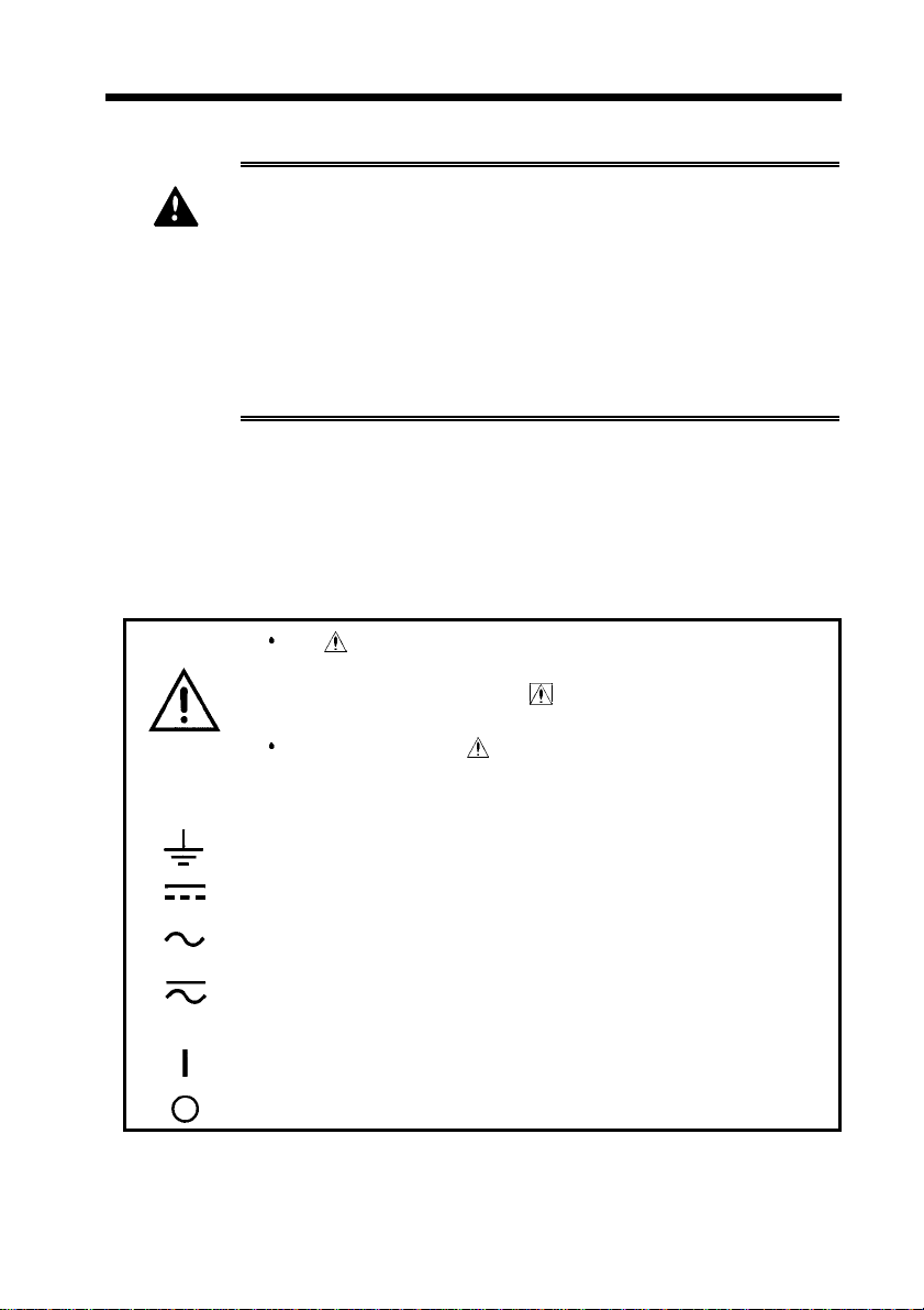
SafetyNotes
This instrument is designed to conform to IEC 61010
Safety Standards, and has been thoroughly tested for
DANGE
Safety Symbols
safety prior to shipment. However, mishandling
during use could result in injury or death, as well as
damage to the instrument. Be certain that you
understand the instructions and precautions in the
manual before use. We disclaim any responsibility for
accidents or injuries not resulting directly from
product defects.
This manual contains information and warnings essential
for safe operation of the instrument and for maintaining it
in safe operating condition. Before using the instrument,
be sure to carefully read the following safety notes.
The symbol printed on the instrument indicates that
the user should refer to a corresponding topic in the
manual (marked with the
relevant function.
In the manual, the symbol indicates particularly
important information that the user should read before
using the instrument.
symbol) before using the
Indicates a grounding terminal.
Indicates DC (Direct Current).
Indicates AC (Alternating Current).
Indicates both DC (Direct Current) and AC (Alternating
Current).
Indicates the ON side of the power switch.
Indicates the OFF side of the power switch.
______________________________________________________________
Safety Notes
Page 8

iv
R
W
_____________________________________________________________________
The following symbols in this manual indicate the relative
importance of cautions and warnings.
Indicates that incorrect operation presents an extreme
DANGE
hazard that could result in serious injury or death to
the user.
Indicates that incorrect operation presents a
ARNING
CAUTION
significant hazard that could result in serious injury or
death to the user.
Indicates that incorrect operation presents a
possibility of injury to the user or damage to the
instrument.
NOTE
Advisory items related to performance or correct
operation of the instrument.
Accuracy
We define measurement tolerances in terms of f.s. (full
scale) values, with the following meanings:
f.s.
(maximum display or scale value, or length of scale)
Signifies the maximum display (scale) value or the length
of the scale (in cases where the scale consists of unequal
increments or where the maximum value cannot be
defined).
In general, this is the range value (the value written on
the range selector or equivalent) currently in use.
______________________________________________________________
Safety Notes
Page 9
_____________________________________________________________________
v
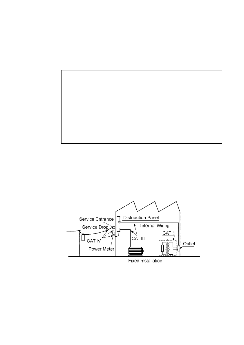
Measurement categories
This instrument complies with CAT III safety requirements.
To ensure safe operation of measurement instruments, IEC
61010 establishes safety standards for various electrical
environments, categorized as CAT II to CAT IV, and called
measurement categories. These are defined as follows.
CATII
CATIII
CATIV
Primary electrical circuits in equipment connected to an
AC electrical outlet by a power cord (portable tools,
household appliances, etc.)
CAT II covers directly measuring electrical outlet
receptacles.
Primary electrical circuits of heavy equipment (fixed
installations) connected directly to the distribution panel,
and feeders from the distribution panel to outlets.
The circuit from the service drop to the service entrance,
and to the power meter and primary overcurrent
protection device (distribution panel).
Using a measurement instrument in an environment
designated with a higher-numbered category than that for
which the instrument is rated could result in a severe
accident, and must be carefully avoided.
Use of a measurement instrument that is not CAT-rated in
CAT II to CAT IV measurement applications could result in
a severe accident, and must be carefully avoided.
______________________________________________________________
Safety Notes
Page 10
vi
R
_____________________________________________________________________
Notes on Use
Follow these precautions to ensure safe operation and to
obtain the full benefits of the various functions.
The maximum input voltage is 600 V DC/AC. Attempting
DANGE
to measure voltage in excess of the maximum input
voltage could destroy the instrument and result in
personal injure or death.
The maximum rated voltage between input terminals
and ground is 600 Vrms. Attempting to measure
voltages exceeding 600 V with respect to ground could
damage the instrument and result in personal injury.
Connection cords or clamp-on sensor should be made
only at the secondary side of a breaker, so the breaker
can prevent an accident if a short circuit occurs.
Connections should never be made to the primary side
of a breaker, because unrestricted current flow could
cause a serious accident if a short circuit occurs.
To avoid short circuits and potentially life-threatening
hazards, never attach the clamp to a circuit that
operates at more than the maximum rated voltage, or
over bare conductors.
To avoid electric shock, do not allow the instrument to
WARNING
get wet, and do not use it when your hands are wet.
To avoid electric accidents and to maintain the safety
specifications of this instrument, connect the power
cord provided only to a 3-contact (two-conductor +
ground) outlet.
To avoid electric shock when measuring live lines,
wear appropriate protective gear, such as insulated
rubber gloves, boots and a safety helmet.
Do not use the product where it may be exposed to
corrosive or combustible gases. The product may be
damaged or cause an explosion.
______________________________________________________________
Notes on Use
Page 11
_____________________________________________________________________
vii
CAUTION
This instrument is designed for indoor use, and operates
reliably from 5 to 40℃.
Do not store or use the instrument where it could be
exposed to direct sunlight, high temperature or humidity, or
condensation. Under such conditions, the instrument may
be damaged and insulation may deteriorate so that it no
longer meets specifications.
This instrument is not designed to be entirely water- or
dust-proof. To avoid damage, do not use it in a wet or
dusty environment.
To operate from DC power, pay careful attention to polarity
when making power connections, and set the power source
switch to the DC position (
changing the power source, unplug the (
) before use. Also, before
) power cord
from the outlet to prevent hazards, and remove the
connection cord from any object under test.
Avoid stepping on or pinching the cable, which could
damage the cable insulation.
Keep the cables well away from heat sources, as bare
conductors could be exposed if the insulation melts.
To prevent an electric shock accident, confirm that the
white or red portion (insulation layer) inside the cable is not
exposed. If a color inside the cable is exposed, do not use
the cable.
Be careful to avoid dropping the clamps or otherwise
subjecting them to mechanical shock, which could damage
the mating surfaces of the core and adversely affect
measurement.
Keep the clamp jaws and core slits free from foreign
objects, which could interfere with clamping action.
For shipping or long-term storage, be certain that the
recording head is in the raised position. Otherwise the
rollers could be deformed and cause uneven printing.
NOTE
Use only recording paper specified by Hioki. Non-specified
recording paper may result in poor-quality or blank printouts.
Avoid using the printer in hot, humid environments, as this can
greatly reduce printer life.
Accurate measurement may be impossible in the presence of
strong magnetic fields, such as near transformers and highcurrent conductors, or in the presence of strong electromagnetic
fields such as near radio transmitters.
This instrument may cause interference if used in residential
areas. Such use must be avoided unless the user takes special
measures to reduce electromagnetic emissions to prevent
interference to the reception of radio and television broadcasts.
______________________________________________________________
Notes on Use
Page 12

viii
y
_____________________________________________________________________
Chapter Summar
This manual consists of the following chapters.
"Introduction", "Safety Notes", "Notes on Use" describe
precautions on use, overview, and features of this unit.
Be sure to read them all. Next, check Chapter 1 to 5 and
the unit to confirm your understanding of the function.
Chapter 1 Product Overview
Outlines the product and explains the names and functions
of its parts.
Chapter 2 Measurement Procedures
Explains procedures for measurement using the product.
Chapter 3 Changing the Recording Paper
Explains how to replace the recording paper.
Chapter 4 Specifications
Sets forth specifications of the product.
Chapter 5 Maintenance and Service
Provides information maintenance and service information
for the product.
______________________________________________________________
Chapter Summary
Page 13

_____________________________________________________________________
1
Chapter 1
Product Overview
______________________________________________________________
Product Overview
Page 14

2
_____________________________________________________________________
1.1 Product Overview
The multi-functional recording Model 8206-10 MICRO
HiCORDER is almost as easy to use as a simple DMM.
This instrument features the capability to simultaneously
record voltage and current (When using the optional clamp-
on sensor), such as is often required for AC power
management, as well as providing input voltage ranges
corresponding to standard commercial mains voltages.
Voltage can be measured and recorded with magnified
display resolution (approximately doubled) around the
centered standard voltage. This feature is ideally suited to
AC power systems management and inspection.
______________________________________________________________
Product Overview
Page 15

_____________________________________________________________________
3
1.2 Features
(1) Easy operation
The large single-function controls allow operation without
requiring repeated reference to the manual.
(2) Graduated analog-style amplitude display
The high-resolution graduated display and data display
matching the selected range allow input signal levels to be
viewed like an analog meter.
(3) Recording paper printout
Setup conditions for recorded data and elapsed time are
printed out with recorded measurements, eliminating the
need for complex multiple printouts for record storage and
reporting.
(4) Simultaneous Voltage and Current Recording
Voltage and current can be recorded either simultaneously
or independently.
(5) Ranges Correspond to Standard Mains Voltages
The ranges are designed to correspond to standard
commercial mains ratings. Also, to aid in measuring
voltages that deviate considerably from standard ratings, a
POSITIO N control allows offsetting the display area,
facilitating applicability in a wide variety of circuits.
(6) Dual power supply system
Power can be supplied from either the AC mains or a 12-V
DC source. AC mains supply voltages between 100 to 240
V AC are automatically selected.
(7) Handy carrying case
The supplied carrying case includes storage for the power
cord and recording paper.
______________________________________________________________
Product Overview
Page 16
4
_____________________________________________________________________
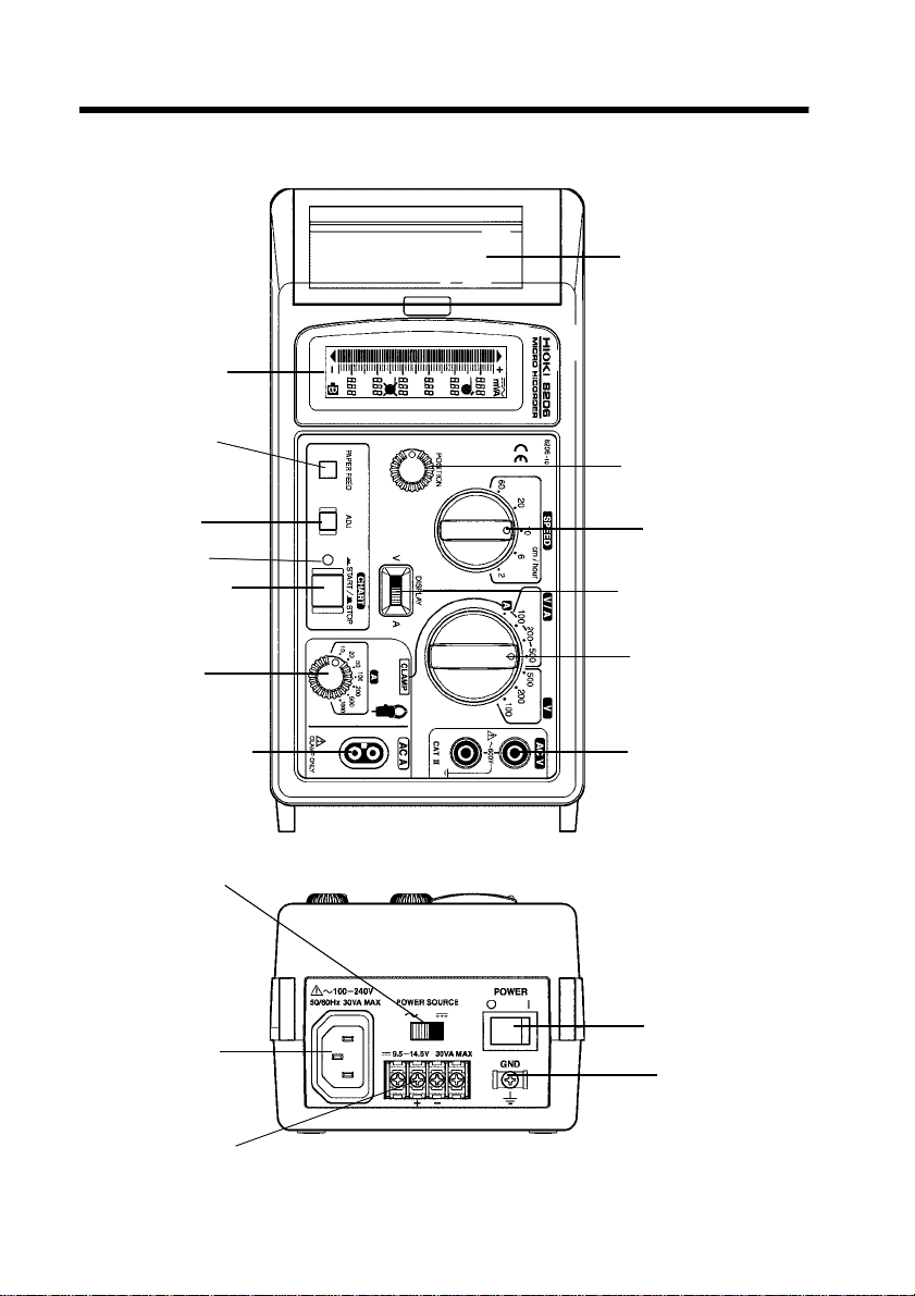
1.3 Front Panel
Printer Cover
LCD (display)
PAPER FEED
Button
POSITION Control
ADJ Button
Indicator
CHART Button
A (CLAMP)
Selector
Clamp Terminals
POWER SOURCE Switch
AC Connector
SPEED Selector
DISPLAY Switch
RANGE Selector
Test Voltage Input
Terminals
POWER Switch
GND Terminal
DC Terminals (DC Power Source)
______________________________________________________________
Product Overview
Page 17
_____________________________________________________________________
5
LCD (display) Displays the signal level and device status, including
selected mode and range, numeric scale values, and
indicators. States such as print head up, out of paper and
low supply voltage are also displayed.
PAPER FEED
Button
ADJ Button Adjusts the zero-reference point for measurements
Indicator This indicator l ights when the
CHART Button Starts and stops recording
A (CLAMP)
Selector
Clamp Terminals Connect a clamp-on sensor to these terminals to measure current
Test Voltage
Input Terminals
RANGE Selector Selects the measurement signal type and amplitude range
DISPLAY Switch When you are recording voltage and current simultaneously
SPEED Selector Sets the transport speed of the recording paper
POSITION
Control
Printer Cover Covers the printer mechanism and recording paper storage
POWER
SOURCE Switch
AC Connector Connect the AC cord here to operate the recorder from
DC Terminals (DC
Power Source)
GND Terminal This is a signal reference ground to establish a reference
POWER Switch Turns the recorder on an off
Manually advances the recording paper
Pressing this button momentarily advances the paper about
30 mm. Holding this button advances the paper
continuously.
CHART
START state, and blinks when the print head is up and at
paper end (in the START state).
Selects input sensitivity to match a connected clamp-on
sensor (when used), and applies that sensitivity internally
so that the range setting prints appropriately on the
recording paper
Apply the test voltage across these terminals for
measurement
(V/A range selected), you can set this switch to either A or
V, according whether you wish the LCD to display current
or voltage.
When voltage measurement is selected, this switch
moves the center value for enlarged display.
Selects whether the recorder is to be powered from AC
mains, or DC
commercial power (100 to 240 V AC)
Connect a 12-V (nominal) DC supply to these terminals to
operate the recorder from DC power
for eliminating stray effects such as noise from
measurements
button is in the
______________________________________________________________
Product Overview
Page 18

6
.
_____________________________________________________________________
1.4 LCD (Display)
*Subunits (m)
*Positive
Over-range Indicator
Pointer
Under-range Indicator
*Negative
Pointer The input signal level is indicated by the lit segment
(pointer) in the graduated bar-type scale
Over-range Indicator This arrow lights when the input signal exceeds the
upper limit of the selected range (the highest level
segment lights at the same time).
Under-range Indicator This arrow lights when the input is below the lower
limit of the selected range (the lowest level segment
lights at the same time).
Low (DC) Supply
Voltage Indicator
Numeric Display These numeric values are the amplitude values of the
Paper End Indicator Lights when no recording paper is present.
Scale This graduated scale contains the pointer (lit
Print Head Up
Indicator
Lights when the DC supply voltage is low.
gradations on the meter scale, according to the
selected range (six 3-digit, 7-segment numerals plus
decimal point)
segment) that indicates the input signal level.
Lights when the print head is raised.
*Not used for the 8206-10
*Indicates Direct Current( )
*Indicates Alternating
Current( )
Print Head Up Indicator
Scale
Paper End Indicator
Numeric Display
Low (DC) Supply Voltage
Indicator
______________________________________________________________
Product Overview
Page 19

_____________________________________________________________________
1.5 Printout Information
Example of D/A-100 V range case
7
Setup Range Data 1
Model
Trademark
Setup Range Data 1 The print setup signal type, numeric value of the
Model Prints when the
Trademark Prints when the
Scale Prints when the
Elapsed Time Display Prints at 5-division intervals
Setup Range Data 2 Prints at 10-division intervals, and when the range
Interval Printing
(numeric amplitude)
Printing Waveform Prints when the average mode is selected.
ADJ Data See Section 2.5, Item 9 regarding ADJ button
Printing Waveform
Scale
range and display units are printed once when the
CHART
setting or position control is changed.
The input signal amplitude is printed numerically at
specific intervals.
If the measurable range is widely over range, the
following indications will appear.
OVER(V): Voltage
OVER(A): Current
Unaverage mode: AC, Average mode:
Interval Printing
Elapsed Time Display
button is pushed (ON).
CHART
CHART
CHART
button is pushed (ON)
button is pushed (ON)
button is pushed (ON)
Setup Range Data 2
AC
Recording
Waveform
______________________________________________________________
Product Overview
Page 20

8
_____________________________________________________________________
NOTE
When the V/A range is selected, the recording waveform prints
in two lines. The uppermost signal printed at intervals indicates
the higher recording waveform.
______________________________________________________________
Product Overview
Page 21

_____________________________________________________________________
9
Chapter 2
Measurement Procedures
2.1 Preparations
To avoid electric accidents and to maintain the safety
WARNING
specifications of this instrument, connect the power
cord provided only to a 3-contact (two-conductor +
ground) outlet.
To avoid ele ctrical accidents, turn the power switch off
and unplug the power cords from the outlet after use.
(1) Check the paper
Check the installation condition and amount of paper
remaining before starting a measurement. Refer to Chapter
3 for the paper installation procedure, if necessary.
(2) Connect the power
This product can be operated from either AC mains or 12
V DC.
______________________________________________________________
Measurement Procedures
Page 22

10
_____________________________________________________________________
AC Operation
Set the POWER SOURCE switch to
1.
the
(AC) position.
2. Connect the supplied power cord to the
socket on the recorder.
3. Plug in the power cord. Insert the plug
directly into the outlet.
NOTE
______________________________________________________________
Measurement Procedures
Although the product can operate from 100 to 240 V AC, the
power cord should be selected to conform to the requirements of
the mains voltage used.
To avoid electrical accidents, unplug the power cord from the
outlet after use, and turn the power switch off.
Page 23

_____________________________________________________________________
11
DC Operation
Positive
Negative
1. Set the
the
POWER SOURCE
(DC) position.
switch to
2. Connect the GND terminal to earth
ground.
3. Connect a source of 9.5 to 14-V DC to
the terminals.
From 9.5 to 14-V DCpower source
NOTE
______________________________________________________________
A proper ground connection is important for safety and to
ensure stable operation.
The power wiring should be of sufficient current capability to
handle the power consumption (30 VA maximum) of the
product, with a margin for safety.
Measurement Procedures
Page 24

12
_____________________________________________________________________
NOTE
We recommend the following wiring for power connections.
PVC-insulated ring-type crimp-on terminals
(3.2-mm ID, less than 6-mm OD)
Vinyl-insulated wire, at least 1.25 mm2(#14 AWG)
(3) Powering on
Slide the PO WER switch to the on
1.
position (
The LCD should light. Confirm that no
2.
).
error indicators appear.
(4) Make the appropriate settings for the intended type of
measurement:
To measure AC voltage, see Section 2.2, AC Voltage
Measurement.
To measure AC current, see Section 2.3, AC Current
Measurement.
To measure AC current, see Section 2.4, AC Voltage and
Current Measurement.
______________________________________________________________
Measurement Procedures
Page 25

_____________________________________________________________________
R
W
2.2 AC Voltage Measurement
To avoid electric shock, short circuits and damage to
13
DANGE
the instrument, observe the following precautions:
The maximum input voltage is 600 V DC/AC.
Attempting to measure voltage in excess of the
maximum input voltage could destroy the instrument
and result in personal injure or death.
The maximum rated voltage between input terminals
and ground is 600 Vrms. Attempting to measure
voltages exceeding 600 V with respect to ground
could damage the instrument and result in personal
injury.
When connecting clip-type connection cords to live
terminals, be very careful to avoid accidentally
shorting conductors together and causing a serious
accident.
Connection cords should be made only at the
secondary side of a breaker, so the breaker can
prevent an accident if a short circuit occurs.
Connections should never be made to the primary
side of a breaker, because unrestricted current flow
could cause a serious accident if a short circuit
occurs.
If the input signal level is unknown, begin measuring
with the highest range to determine the approximate
signal level, then select the appropriate range for
actual measurement.
Disconnect the connection cords from the
measurement object before switching ranges.
To avoid electrical shock, be careful to avoid shorting
ARNING
CAUTION
live lines with the connection cords.
For safety reasons, use only the supplied connection cords
to connect the instrument input terminals to the circuit to
be tested.
______________________________________________________________
Measurement Procedures
Page 26

14
_____________________________________________________________________
Example 1
Recording voltage changes at a breaker.
Estimated test voltage: 200 V AC
Recording period: 24 hours
1. The supplied connection cord
connect to the Test voltage input
terminals.
2. Set the Range selector to
200 V
,
corresponding to the input signal level.
(Select the voltage of the part to divide
by V.)
______________________________________________________________
Measurement Procedures
Page 27

_____________________________________________________________________
Adjust the POSITION control to display
3.
15
140 to 240 V (see Section 2.5, Item 3
regarding POSITION control
adjustment).
Set the SPEED selector to 10 cm/hour
4.
(according to particular application).
5. Press the
ADJ
button to reset the zero
position. (see Section 2.5, Item 9
regarding ADJ button).
6. Connect the connection cord in parallel
with the device under test.
7. Press the
CHART
button to begin
measuring.
8. Record for 24 hours.
9. Press the
recording.
______________________________________________________________
CHART
button again to stop
Measurement Procedures
Page 28

16
_____________________________________________________________________
10.Disconnect the connection cord from the circuit under
test.
11.Press the
PAPER FEED
button to feed out the recording
paper, and cut it off.
12.Turn the POWER switch off ( ).
Inspect the results. In this example, the elapsed time
13.
until the battery voltage decreases to the warning level
can be read from the printout and the scale.
______________________________________________________________
Measurement Procedures
Page 29

_____________________________________________________________________
R
17
2.3 AC Current Measurement
To avoid electric shock, short circuits and damage to
DANGE
the instrument, observe the following precautions:
Clamp-on sensor should be made only at the
secondary side of a breaker, so the breaker can
prevent an accident if a short circuit occurs.
Connections should never be made to the primary
side of a breaker, because unrestricted current flow
could cause a serious accident if a short circuit
occurs.
To avoid short circuits and potentially life-threatening
hazards, never attach the clamp to a circuit that
operates at more than the maximum rated voltage or
over bare conductors.
If the input signal level is unknown, begin measuring
with the highest range to determine the approximate
signal level, then select the appropriate range for
actual measurement.
Disconnect the clamp-on sensor from the
measurement object before switching ranges.
CAUTION
Note that the clamp-on sensor may be damaged if current
exceeding the selected measurement range is applied for a
long time.
To prevent damage to the clamp-on sensor, never connect
or disconnect a sensor while the power is on.
Example 2
Recording current flow through a breaker.
Estimated test current: 30 A
Recording period: 1 hour
______________________________________________________________
Measurement Procedures
Page 30

18
_____________________________________________________________________
Connect the optional clamp-on
1.
sensor to the Clamp terminals.
Set the Range selector to the A position.
2.
3. Set the
A
(CLAMP) selector to
50 A
sensitivity.
4. Set the
SPEED
selector to
60 cm/hour
(according to particular application).
______________________________________________________________
Measurement Procedures
Page 31

_____________________________________________________________________
Press the ADJ button to reset the zero
5.
19
position. (see Section 2.5, Item 9
regarding ADJ button).
6. Clip the clamp on sensor.
OK
NOTE
Attach the clamp around only one conductor. Single-phase (2-
wire) or three-phase (3-wire) cables clamped together will not
produce any reading.
Position the conductor so that it is as nearly centered in the
clamp core as possible.
Non-sinusoidal waveforms such as the secondary side of
inverters may not be measurable.
Depending on the size and frequency of the measured current,
the core of the clamp may hum as a result of resonance. This
does not affect measurement performance.
Do not attempt to measure current levels that are likely to
exceed the specified maximum r ating of the clamp-on sensor.
7. Press the
CHART
button to begin
measuring.
8. Record for 1 hour.
9. Press the
recording.
CHART
button again to stop
______________________________________________________________
Measurement Procedures
Page 32

20
_____________________________________________________________________
10.Remove the clamp from the conductor being measured.
Press the PAPER FEED button to feed out the recording
11.
paper, and cut it off.
Turn the POWER switch off ( ).
12.
13.Inspect the results. In this example, the current flow
through the breaker over ten minutes can be read from
the printout and the scale.
______________________________________________________________
Measurement Procedures
Page 33

_____________________________________________________________________
R
2.4 AC Voltage and Current Measurement
To avoid electric shock, short circuits and damage to
21
DANGE
the instrument, observe the following precautions:
The maximum input voltage is 600 V DC/AC.
Attempting to measure voltage in excess of the
maximum input voltage could destroy the instrument
and result in personal injure or death.
The maximum rated voltage between input terminals
and ground is 600 Vrms. Attempting to measure
voltages exceeding 600 V with respect to ground could
damage the instrument and result in personal injury.
When connecting clip-type connection cords to live
terminals, be very careful to avoid accidentally shorting
conductors together and causing a serious accident.
Connection cords or clamp-on sensor should be
made only at the secondary side of a breaker, so the
breaker can prevent an accident if a short circuit
occurs. Connections should never be made to the
primary side of a breaker, because unrestricted
current flow could cause a serious accident if a short
circuit occurs.
To avoid short circuits and potentially life-threatening
hazards, never attach the clamp to a circuit that
operates at more than the maximum rated voltage or
over bare conductors.
If the input signal level is unknown, begin measuring
with the highest range to determine the approximate
signal level, then select the appropriate range for
actual measurement.
Disconnect the connection cords from the
measurement object before switching ranges.
To avoid electric shock and short-circuit accidents, use
only the supplied connection cords to connect the
instrument input terminals to the circuit to be tested.
To avoid electrical shock, be careful to avoid shorting
WARNING
CAUTION
live lines with the connection cords.
Note that the clamp-on sensor may be damaged if
current exceeding the selected measurement range is
applied for a long time.
To prevent damage to the clamp-on sensor, never
connect or disconnect a sensor while the power is on.
______________________________________________________________
Measurement Procedures
Page 34

22
_____________________________________________________________________
Example 3
Recording current flow through a breaker.
Estimated test voltage: 200 V AC
Estimated test current: 30 A
Recording period: 5 hours
1. The supplied connection cord
connect to the Test voltage input
terminals.
2. Connect the optional clamp-on
sensor to the Clamp terminals.
______________________________________________________________
Measurement Procedures
Page 35

_____________________________________________________________________
23
3. Set the Range selector to
200 V
,
corresponding to the input signal level.
(Select the voltage of the part to divide
by V/A.)
Adjust the POSITION control to display
4.
160 to 260 V (see Section 2.5, Item 3
regarding POSITION control
adjustment).
5. Set the
V
DISPLAY
switch to eitherAor
, according whether you wish the
LCD to display current or voltage,
respectively.
Displays current
______________________________________________________________
Displays voltage
Measurement Procedures
Page 36

24
_____________________________________________________________________
Set the SPEED selector to 10 cm/hour
6.
(according to particular application).
NOTE
7. Press the
ADJ
button to reset the zero
position. (see Section 2.5, Item 9
regarding ADJ button).
Connect the connection cord in parallel
8.
with the device under test.
Clip the clamp on sensor.
9.
OK
Attach the clamp around only one conductor. Single-phase (2wire) or three-phase (3-wire) cables clamped together will not
produce any reading.
Position the conductor so that it is as nearly centered in the
clamp core as possible.
Non-sinusoidal waveforms such as the secondary side of
inverters may not be measurable.
Depending on the size and frequency of the measured current,
the core of the clamp may hum as a result of resonance. This
does not affect measurement performance.
Do not attempt to measure current levels that are likely to
exceed the specified maximum r ating of the clamp-on sensor.
______________________________________________________________
Measurement Procedures
Page 37

_____________________________________________________________________
Press the CHART button to begin
10.
25
measuring.
11.Record for 5 hours.
12.Press the
CHART
button again to stop
recording.
13.Disconnect the connection cord from the circuit under
test.
Remove the clamp from the conductor being measured.
14.
15.Press the
PAPER FEED
button to feed out the recording
paper, and cut it off.
16.Turn the POWER switch off ( ).
Inspect the results. In this example, changes in voltage
17.
and current through the breaker for five hours can be
read from the printout and the scale.
______________________________________________________________
Measurement Procedures
Page 38

26
_____________________________________________________________________
2.5 Common Measurement Operations
(1) Starting and ending recording
Pressing the
pressing it again (to return it to the undepressed STOP
position) ends recording.
NOTE
The PAPER FEED button and ADJ button are disabled while
the CHART button is depressed (ON).
Changing the range during recording, the new scale is printed.
(2) Paper transport speed
Use the
NOTE
Settings can be changed during recording, but the setting
information cannot be printed. Check the elapsed time printed
on the paper.
(3) POSITION control
For voltage measurement (Range selector set to V/A or V),
the central value on the magnified display can be offset in
steps equal to 10% of the range limit. This function is
useful in cases where the actual voltage of a circuit under
test differs from standard voltage ratings.
Display Example of 200-V DC Range Case
CHART button down starts recording, and
SPEED
selector to set the paper transport speed.
g
n
i
t
t
e
S
N
O
I
T
I
S
O
P
m
u
m
i
n
i
M
______________________________________________________________
Measurement Procedures
g
n
i
t
t
e
S
N
O
I
T
I
S
O
P
r
e
t
n
e
C
g
n
i
t
t
e
S
N
O
I
T
I
S
O
P
m
u
m
i
x
a
M
Page 39

_____________________________________________________________________
27
(4) PAPER FEED button
Use this button for manual paper recording.
Pressing this button momentarily advances the paper about
30 mm. Holding this button advances the paper
continuously.
NOTE
The button is disabled during automatic recording.
(5) DISPLAY Switch
When you are recording voltage and current simultaneously
(V/A range selected), you can set this switch to either A or
V, according whether you wish the LCD to display current
or voltage, respectively.
(6) Range selector
Set according to the expected maximum amplitude of the
measured signal.
(7) AC current measurement
To measure AC current using an optional clamp-on sensor,
connect the clamp-on sensor to the clamp terminals and set
the range selector to A. (Set the Range selector to V/A to
record voltage and current simultaneously, or set to the A
position to record only current.) Also, set the A (CLAMP)
selector to match the input sensitivity of the clamp with the
expected maximum current to be measured.
(8) Printing waveforms
Either average or peak values can be selected for waveform
printing. The selection is made when turning the power on
(when the power is off, the standard condition is selected).
Unaveraged mode (standard setting)
The printed waveform consists of the minima and maxima
points of the data sampled between printing intervals. This
mode is useful for recording rapid changes in input signals,
such as instantaneous electrical faults.
______________________________________________________________
Measurement Procedures
Page 40

28
_____________________________________________________________________
Average mode
The printed waveform consists of the average of the data
points between printing intervals.
The printing waveform mode is displayed as AC
_
.
The following shows the relation between the paper
transport speeds and intervals.
Papertransport speed Intervals
60 cm/hour 750 ms
20 cm/hour 2.25 s
10 cm/hour 4.5 s
6 cm/hour 7.5 s
2 cm/hour 22.5 s
Average mode
Hold the PAPER FEED button
while turning the POWER switch on.
NOTE
Standard Condition
Continuing to hold the switch causes the paper to feed.
______________________________________________________________
Measurement Procedures
Page 41

_____________________________________________________________________
29
(9) ADJ button
Press this button to adjust the fine offset of the zero
position during measurement. While shorting the connection
cord together, press this button to reset the zero position.
After adjusting the zero position, the "0" in the numeric
display of the LCD changes to "0.0", the "0" in the range
setting information for the recording paper changes to
"0.0", and "_" appears under the unit display.
Before adjusting
NOTE
______________________________________________________________
This button is intended only for fine adjustment of the zero
position. It cannot compensate for a large offset.
The zero adj ustment is lost when power is turned off or range
selector setting is changed, so reset the zero position again if
necessary when power is turned on.
The button is disabled during automatic recording.
After verifying that input is 0, press the ADJ button. To ensure
zero input, either short the tips of the connection cords or short
the test voltage input terminals. Measurement error will be larger
in any input is present when the ADJ button is pressed.
・For accurate measurements, press the ADJ button only when the
conductor is not clamped and the core junction is closed (when
the input value is 0).
・After changing the range, press the ADJ button to reset the zero
position.
After adjusting
Measurement Procedures
Page 42

30
_____________________________________________________________________
______________________________________________________________
Measurement Procedures
Page 43

_____________________________________________________________________
31
Chapter 3
Changing the Recording Paper
3.1 Opening and Closing the Printer Cover
CAUTION
Avoid forcing the printer cover, as the hinge could break.
Opening the Printer Cover
Hook your fingertip under the projecting part
1.
of the printer cover, and pull it up slightly to
disengage the catch.
2. Open the cover when the catch is disengaged.
Closing the Printer Cover
1. Confirm that some paper is sti cking out
before closing the printer cover.
2. Align the hook in the cover with the catch on
the unit, and press the cover lightly until the
catch engages.
______________________________________________________________
Changing the Recording Paper
Page 44

32
_____________________________________________________________________
3.2 Installing Recording Paper
Head up/down lever
Recording paper
Recording paper
Platen
Roll paper spool
Print head
Guide shaft
Raise the print head. Move the
1.
head up/down lever up to raise
the print head.
2. Insert the spool into the
recording paper roll.
Install the spool and paper roll
3.
into the holder.
Feed the paper over the guide
4.
shaft.
5. Feed the paper over the platen
and out through the printer
frame.
6. Confirm that the paper is
centered on the platen, and move
the lever down to lower the print
head.
NOTE
______________________________________________________________
Changing the Recording Paper
Printing is not possible if the recording paper is loaded wrongside up.
The paper may jam if it is not aligned with the roller.
Page 45

_____________________________________________________________________
Chapter 4
Specifications
4.1 General Specifications
Recording system Thermal recording paper
Input channels 2 (Each channel sampled alternately)
Sampling period 10 ms
Valid recording width Waveform recording width: 60 mm
33
Paper transport
speeds
2, 6, 10, 20 or 60 cm/hour
Recording axis
precision
Operating
temp./humidity
Storage
temp./humidity
Guaranteed accuracy
signal frequency
Operating temperature
and humidity for
guaranteed accuracy
Period of guaranteed
accuracy
Operating
environment
Withstand voltage 4.29 kVrms (50/60 Hz, 1 min)
Power requirements AC: 100 to 240 V, 50/60 Hz, 30 VA
Within 0.5%
5to40oC (41 to 104 ), 35 to 80% RH (noncondensating)
-10to50oC (14 to 122 ), 80% RH or less (noncondensating)
45 to 66 Hz
23 5oC(73 41 ), 35 to 80% RH (non-condensating)
1 year
Indoors, below 2000 m (6562 feet) altitude
between GND and input terminals
DC: 9.5 to 14 V, 30 VA
(Voltage fluctions of 10% from the rated supply
voltage are taken into account. )
______________________________________________________________
Specifications
Page 46

34
_____________________________________________________________________
External dimensions
and mass
Accessories 9344 CARRYING CASE 1
Options 9235 RECORDING PAPER (15 m, 10 rolls) 1
Applicable Safety:
Standards
EMC:
Approx. 250W 122H 93.5D mm
(9.84"W
Approx. 1200 g (42.3 oz.)
L9257 CONNECTOR CORD 1
9235 RECORDING PAPER (15 m) 1
Roll Paper Spools 2
AC Power Cord 1
Instruction Manual 1
9236-01 RECORDING PAPER
9650 CLAMP ON SENSOR 1
9651 CLAMP ON SENSOR 1
9668 CLAMP ON SENSOR 1
EN61010
Pollution Degree 2, Measurement category III
(6000 V expected transient Overvoltage)
EN61326 Class A
EN61000-3-2
EN61000-3-3
4.8"H 3.68"D)
(15 m, Climate-resistant; 10 rolls) 1
______________________________________________________________
Specifications
Page 47

_____________________________________________________________________
4.2 Voltage Measurement Input Specifications
35
Measurement ranges
(based on standard
ratings)
Maximum input voltage 600 Vrms
Maximum rated voltage
between input
terminals and ground
Input impedance 1MΩ 5%
Accuracy Within 2% of the maximum graduated value (the
Rectification system Effective value rectification
Common mode
rejection ratio
Frequency
characteristics
Effect of electromagnetic
interference
100, 200 and 500 V AC (rated value of the range can
be adjusted within
steps) The display can be magnified to show the area
between +25 and -35% of the measurement range.
600 Vrms
maximum graduated value is 25% above the rated
value of the range)
Better than 50 dB (50/60 Hz, less than 100Ω unbalance)
Within +0.5, -3 dB for the range between 30 Hz to 30
kHz, using 50/60 Hz as the standard reference point.
Within +5, -0.5%f.s. at 3 V/m
20% of standard ratings in 10%
______________________________________________________________
Specifications
Page 48

36
_____________________________________________________________________
4.3 Current Measurement Input Specifications
Measurement ranges
(max. ratings)
Input sensitivity 10, 20, 50, 100, 200, 500, 1000 mA f.s.
Input impedance 1 Ω 10%
Accuracy Within 2% of max. rating
Rectification system Effective value rectification
Frequency
characteristics
Range information Sensitivity and display range are determined by the
Effect of
electromagnetic
interference
10, 20, 50, 100, 200, 500, 1000 AAC (depending on
clamp-on sensor used). Maximum display range is
110% of measurement range.
(f.s. = max. rating)
(10, 20, 50, 100, 200, 500 A range)
Within 3% of max. rating (1000 A range)
Within +0.5, -3 dB for the range between 20 Hz to 20
kHz, using 50/60 Hz as the standard reference point
(independent of clamp-on sensor characteristics).
Clamp Range input selector setting.
Within +10, -1%f.s. at 3 V/m
The full-scale accuracy of the ranges of each clamp-on sensor is as
follows.
Range
model
9650 1.8% 1.65% 1.56% 1.53%
9651 3.0% 2.25% 1.8% 1.65% 1.58% 1.53%
9668 6.0% 4.5% 3.6% 3.3% 3.15% 3.06% 3.03%
10 A 20 A 50 A 100 A 200 A 500 A 1000 A
______________________________________________________________
Specifications
Page 49

_____________________________________________________________________
37
Overall accuracy is the cumulative accuracy of the recorder and the
probe, as indicated in the following examples.
(Examples)
1. For the 100-A range, combining the accuracy of the recorder and the
9650 yields an overall accuracy of
range,
3.56% f.s.
3.53% f.s., and for the 50-A
2. For the 500-A range, combining the accuracy of the recorder and the
9651 yields an overall accuracy of
range,
3.65% f.s.
3.53% f.s., and for the 100-A
3. For the 1000-A range, combining the accuracy of the recorder and the
9668 yields an overall accuracy of
range,
5.3% f.s.
6.03% f.s., and for the 100-A
NOTE
When using the 9668 CLAMP ON SENSOR in conjunction with
the 8205-10 to measure current, we do not recommend t a king
measurements at high sensitivities. We do recommend using a
clamp that is suited to the current to be measured.
4.4 Display Specifications
Display method Signal level and setting data displayed by LCD bar
Display contents Signal input level (V):
The display can be magnified to show the area between
+25 and -35% of the measurement range. (rated value of
the range can be adjusted within
atings in 10% steps)
Maximum displayable voltage = 725 V AC
Minimum resolvable voltage =
Voltage: 1% of the rated value of the range
Current: 2% of the rated value of the range
Signal input level (A):
0 to 110% of range rating
Minimum resolution = 2% of range rating
Low Supply Voltage (when operating on DC)
Print Head Up
Paper End
Type of Signal Measurement
Measured signal units and subunits
20% of standard
______________________________________________________________
Specifications
Page 50

38
_____________________________________________________________________
4.5 Recorded Information
Waveform data Voltage or current amplitude. Waveform data may be
either average or unaveraged values (set at power on)
Settings Range, mode, etc. print at start and stop, and at each
10 DIV (format differs when printed at intervals)
Elapsed time Elapsed time from starting to record are printed at
each 5 DIV
Interval printing Measured values print along grid at each 2 DIV
Printing when setting
change
Changes in various settings during recording are
printed after the changes are made
4.6 Recording Time
The following table shows the recording capacity of one
roll of recording paper.
Papertransport speed Recording time
2 cm/hour 31.25 days
6 cm/hour 10.43 days
10 cm/hour 6.25 days
20 cm/min 75 hours
60 cm/min 25 hours
______________________________________________________________
Specifications
Page 51

_____________________________________________________________________
39
Chapter 5
Maintenance and Service
5.1 Storage Precautions
(1) Recorder
Avoid storing the product in conditions of high temperature
and humidity, as damage may result from condensation and
corrosion.
During long-term storage and during transportation, the
print head should be in the raised position. Leaving the
print head in the lowered position for an extended period
can dent the platen (rubber roller) that transports the paper,
resulting in uneven printing.
(2) Storing recording paper
o
Store rolls of thermal paper at no more than 4 0
The paper will change color if exposed to light over a long
period, so do not unwrap a roll of paper until you are ready
to use it.
______________________________________________________________
Maintenance and Service
C.
Page 52

40
_____________________________________________________________________
(3) Storing recordings
As the recording paper is thermally sensitive, be aware of
the following points:
To avoid paper discoloration, do not expose it to direct
o
sunlight, and store at no more than 40
C and 90% RH.
For permanent storage of important recorded data,
photocopy the recording paper.
If the thermal paper is exposed to an organic solvent such
as alcohol or ketone, it may no longer develop properly,
and recorded data may fade.
Also, the thermal recording paper is ruined by contact with
wet Daizo copy paper.
5.2 Cleaning
To clean the instrument, wipe it gently with a soft cloth
moistened with water or mild detergent. Never use solvents
such as benzene, alcohol, acetone, ether, ketones, thinners
or gasoline, as they can deform and discolor the case.
______________________________________________________________
Maintenance and Service
Page 53

_____________________________________________________________________
41
5.3 Cleaning the Printer Head
To maintain print quality, use the following method to
clean the print head whenever recording paper is replaced.
Method 1
ADJ
NOTE
1. Turn on the printer's power while holding down the
button.
2. Print solid black for about 50 cm, and the printer should
turn on as usual. (Press the PAPER FEED button to stop
at any time.)
Print solid black several times to confirm whether
3.
printing has improved. If it does not improve, perform
Method 2.
Method 2
1. Apply a solvent such as a non-water alcohol or normal
hexane, to the recording paper and insert it into the
printer. The recording paper may change color depending
on the solvent you use, so use the reverse side.
2. Move the head up/down lever to the down position.
3. Move the recording paper back and forth with your hand
to clean the head.
Do not use organic solvents such as thinner or benzene, which
could discolor or deform the printer.
After applying a solvent, be certain that the printer is completely
dry before use to avoid discoloring or deforming the printer.
After prolonged use, white paper dust may build up on the
surface of the paper roller. Small amounts of paper dust will not
affect printer operation. However, you may remove it using a
blower brush, such as those used for cameras.
Cut the recording paper with the cutter attached to the printer's
cover. If you cut the recording paper against the side of the
printer head, large amounts of paper dust will stick to the paper
rolle.
______________________________________________________________
Maintenance and Service
Page 54

42
_____________________________________________________________________
5.4 Service
If damage is suspected, check the "Troubleshooting" section
before contacting your dealer or Hioki representative. Pack
the instrument carefully so that it will not be damaged
during shipment, and include a detailed written description
of the problem. Hioki cannot be responsible for damage
that occurs during shipment.
Troubleshooting
Symptom Cause Remedy
Does not turn on POWER SOURCE switch
may be set incorrectly
Power cord may be broken Check and replace cord.
Does not print Paper may be installed
upside down
Set to match power source.
Reinstall the paper
Measured values
unstable
Input signals do not
display
Ground not connected Connect the GND terminal
to earth ground
A connection cord may be
open
Check and replace
connection cord
______________________________________________________________
Maintenance and Service
Page 55

Page 56

 Loading...