

Page 1

OPERATION GUIDE
7015
SIGNAL SOURCE
Page 2

Page 3

1
――――――――――――――――――――――――――
SOURCE FUNCTIONS
1. source DCCV function
(1) Set the slide switch to
M/S
position
(2) Rotate FUNCTION SWITCH from OFF to CV
(3) Press
(4) Press
SHIFT
MODE
to source standby mode
proper times to select 1.5V range or 15V
range
(5) Press
(6) Press
(7) Press
or to select digit adjustment
or
▲
OUTPUT
to set the value of digit
▼
to output DCCV source
2. source DCCC function
(1) Set the slide switch to
M/S
(2) Rotate FUNCTION SWITCH from OFF to CC
(3) Press
SHIFT
to source standby mode
position
(4) Press or to select digit adjustment
(5) Press
(6) Press
or
▲
OUTPUT
▼
to set the value of digit
to output DCCC source
3. source SCAN DCCV(DCCC) CONTINUOUS
function
(1) Set the slide switch to
M/S
(2) Rotate FUNCTION SWITCH from OFF to CV(CC)
(3) Press
(4) Press
SHIFT
MODE
to source standby mode
proper times for
also choose 1.5V or 15V range)
(5) Press
proper times to select
position
SCAN
CONTINUE
(In case CV,
(6) Press
OUTPUT
to output DCCV(DCCC) source
―――――――――――――――――――――――
Page 4
2
――――――――――――――――――――――――――
4. source SCAN DCCV(DCCC) CYCLE function
(1) Set the slide switch to
M/S
position
(2) Rotate FUNCTION SWITCH from OFF to CV(CC)
(3) Press
(4) Press
SHIFT
MODE
to source standby mode
proper times for
SCAN
(In case CV,
also choose 1.5V or 15V range)
(5) Press
(6) Press
proper times to select
OUTPUT
to output DCCV(DCCC) source
CYCLE
5. source SCAN DCCV(DCCC) STEP function
(1) Set the slide switch to
M/S
(2) Rotate FUNCTION SWITCH from OFF to CV(CC)
(3) Press
SHIFT
to source standby mode
position
(4) Press
MODE
proper times for
also choose 1.5V or 15V range)
(5) Press
(6) Press
(7) Press
proper times to select
OUTPUT
or
▲
to output DCCV(DCCC) source
to change STEP output
▼
SCAN
STEP
(In case CV,
―――――――――――――――――――――――
Page 5
3
――――――――――――――――――――――――――
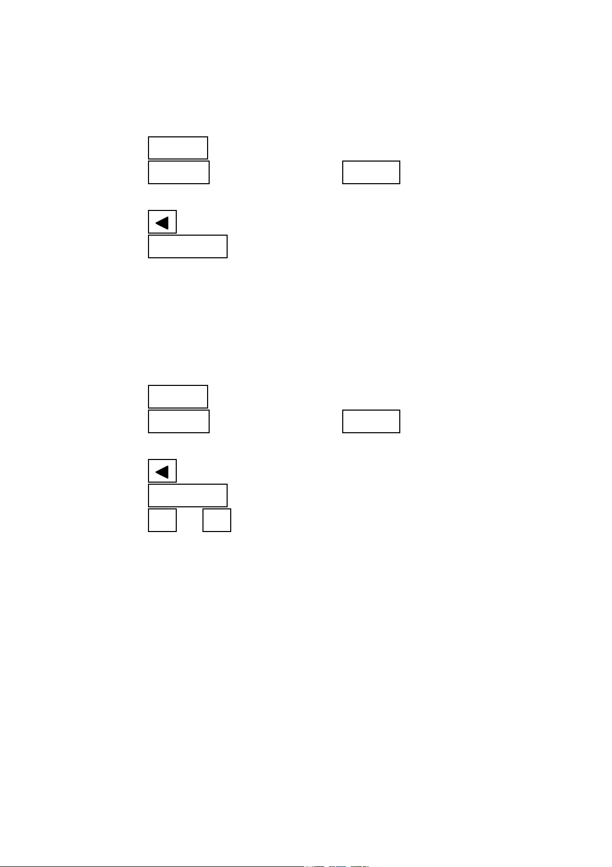
6. source SCAN DCCV(DCCC) output
adjustment
(1) Set the slide switch to
M/S
position
(2) Rotate FUNCTION SWITCH from OFF to CV(CC)
(3) Press
(4) Press
SHIFT
MODE
to source standby mode
proper times for
SCAN
(In case CV,
also choose 1.5V or 15V range)
(5) Press
(6) Press
MODE
MODE
again and hold 1 second
to cycle through STEP, TIME
INTERVAL and AMPLITUDE adjustments
(7) Press
▲
or
to adjust STEP from 1 to 16 and
▼
TIME INTERVAL from 0 to 99
(8) Press
(9) Press
OUTPUT
MODE
to save your setting
again and hold 1 second
7. source RAMP DCCV(DCCC) CONTINUOUS
function
(1) Set the slide switch to
M/S
(2) Rotate FUNCTION SWITCH from OFF to CV(CC)
(3) Press
(4) Press
SHIFT
MODE
to source standby mode
proper times for RAMP (In case CV, also
choose 1.5V or 15V range)
(5) Press
(6) Press
proper times to select
OUTPUT
to output DCCV(DCCC) source
position
CONTINUE
―――――――――――――――――――――――
Page 6

4
――――――――――――――――――――――――――
8. source RAMP DCCV(DCCC) CYCLE function
(1) Set the slide switch to
M/S
position
(2) Rotate FUNCTION SWITCH from OFF to CV(CC)
(3) Press
(4) Press
SHIFT
MODE
to source standby mode
proper times for RAMP (In case CV, also
choose 1.5V or 15V range)
(5) Press
(6) Press
proper times to select
OUTPUT
to output DCCV(DCCC) source
CYCLE
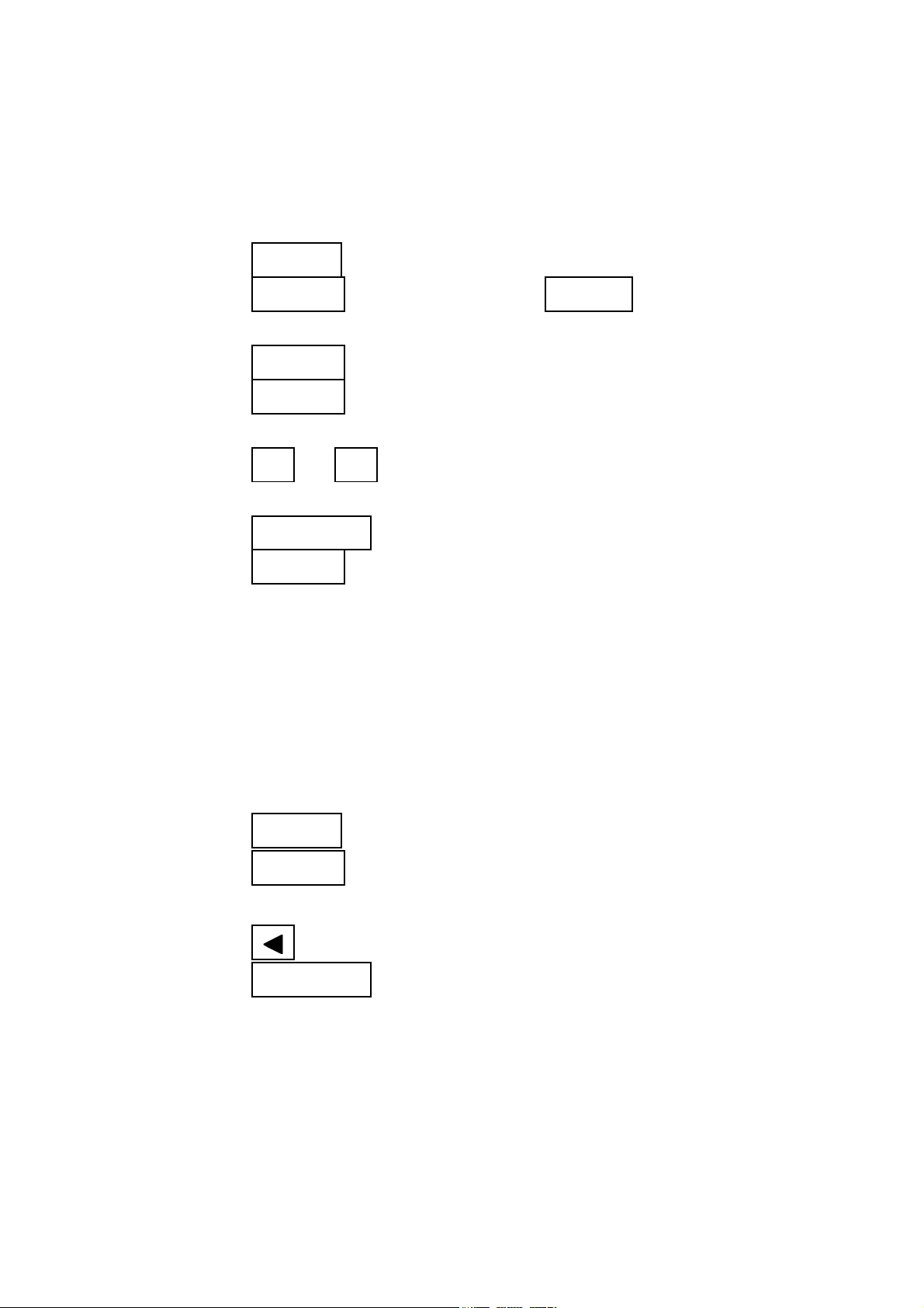
9. source RAMP DCCV(DCCC) output
adjustment
(1) Set the slide switch to
M/S
position
(2) Rotate FUNCTION SWITCH from OFF to CV(CC)
(3) Press
(4) Press
SHIFT
MODE
to source standby mode
proper times for RAMP (In case CV, also
choose 1.5V or 15V range)
(5) Press
(6) Press
MODE
MODE
again and hold for 1 second
to cycle through POSITION,
RESOLUTION and AMPLITUDE adjustments
(7) Press
▲
or
to adjust the RESOLUTION from 1 to
▼
999
(8) Press
(9) Press
OUTPUT
MODE
to save your setting
again and hold 1 second
―――――――――――――――――――――――
Page 7

5
――――――――――――――――――――――――――
10. source PULSE function
(1) Set the slide switch to
M/S
position
(2) Rotate FUNCTION SWITCH from OFF to PULSE
(3) Press
(4) Press
(5) Press
(6) Press
(7) Press
(8) Press
(9) Press
(10) Press
(11) Press
NOTE
・ Set SLIDE SWITCH to
SHIFT
or
▲
MODE
or
▲
MODE
or
▲
MODE
▲
OUTPUT
to source standby mode
to select FREQUENCY
▼
to display DUTY CYCLE
to adjust the DUTY CYCLE
▼
to display PULSE WIDTH
to adjust the PULSE WIDTH
▼
to display AMPLITUDE
or
to select the AMPLITUDE
▼
to output PULSE source
M/S
position for source
functions
・ The inside CIRCLE(FUNCTION) SWITCH labels
are for measurement functions
・ The outside CIRCLE(FUNCTION) SWITCH labels
are for source functions
―――――――――――――――――――――――
Page 8

6
――――――――――――――――――――――――――
NOTE
・ In case FUNCTION SWITCH is at CV, Press
MODE
to cycle through DCCV 1.5V range, DCCV
15V range, SCAN DCCV 1.5 range, SCAN DCCV
15V range, RAMP SCAN DCCV 1.5V range and
RAMP SCAN DCCV 15V range
±
1.5V
SCAN
±
15V
±
15V
SCAN
1.5V
±
SCAN
1.5V
±
SCAN
15V
±
・ In case FUNCTION SWITCH is at CC, Press
MODE
cycle through DCCC 25mA range, SCAN DCCC 25mA
range and RAMP SCAN DCCC 25mA range
±
25mA
SCAN
25mA
±
SCAN
25mA
±
・ In case FUNCTION SWITCH is at PULSE, Press
MODE
to cycle through FREQUENCY(Hz),
DUTY CYCLE(%), PULSE WIDTH(ms) and
AMPLITUDE(V)
to
Hz % ms
Level
―――――――――――――――――――――――
Page 9

7
――――――――――――――――――――――――――
NOTE
・ In case source SCAN DCCV(DCCC) output
adjustment, Press
MODE
to cycle through
STEP(address), INTERVAL TIME(s) and
AMPLITUDE(V)
INTERVAL TIMESTEP AMPLITUDE
・ In case source RAMP SCAN DCCV(DCCC) output
adjustment, Press
MODE
to cycle through START
POSITION, STEPS of RESOLUTION and START
AMPLITUDE(V)
In case you want to change END menu, Press
▲
or
▼
at
START POSITION then you can set STEPS of
RESOLUTION and END AMPLITUDE(V)
START
POSITION
▲
▼
END
POSITION
STEPS of
RESOLUTION
STEPS of
RESOLUTION
START
AMPLITUDE(V)
END
AMPLITUDE(V)
―――――――――――――――――――――――
Page 10

8
――――――――――――――――――――――――――
MEASUREMENT FUNCTION
1. measurement DCV(ACV, ACDCV) function
(1) Set the slide switch to
M
or
M/S
position
(2) Rotate FUNCTION SWITCH from OFF to V or mV
(3) Press
AC/DC
to select DCV(ACV, ACDCV)
measurement
2. measurement DCA(ACA, ACDCA) function
(1) Set the slide switch to
(2) Rotate FUNCTION SWITCH from OFF to mA
(3) Press
AC/DC
to select DCA(ACA, ACDCA)
measurement
M
or
M/S
position
3. measurement OHM function
(1) Set the slide switch to
M
or
M/S
position
(2) Rotate FUNCTION SWITCH from OFF to Ω
(3) Press AC/DC for CONTINUITY
4. measurement TEMPERATURE function
(1) Set the slide switch to
(2) Rotate FUNCTION SWITCH from OFF to mV
(3) Press
REL
(TEMP) and hold for 1 second to display
temperature
(4) Press DUAL to swap
or
M
℃
M/S
and display
position
―――――――――――――――――――――――
Page 11

9
――――――――――――――――――――――――――
5. measurement FREQUENCY function
(1) Set the slide switch to
M
or
M/S
position
(2) Rotate FUNCTION SWITCH from OFF to V, mV or
mA
(3) Press
Hz
once to display FREQUENCY(Hz)
6. measurement DUTY CYCLE function
(1) Set the slide switch to
(2) Rotate FUNCTION SWITCH from OFF to V, mV or
mA
(3) Press
Hz
twice to display DUTY CYCLE(%)
M
or
M/S
position
7. measurement PULSE WIDTH function
(1) Set the slide switch to
M
or
M/S
position
(2) Rotate FUNCTION SWITCH from OFF to V, mV or
mA
(3) Press
Hz
three times to display PULSE WIDTH(ms)
8. measurement DIODE CHECK function
(1) Set the slide switch to
(2) Rotate FUNCTION SWITCH from OFF to DIODE
M
or
M/S
position
―――――――――――――――――――――――
Page 12

10
――――――――――――――――――――――――――
SPECIAL FUNCTION
1. DYNAMIC RECORDING function
(1) Press
recording
(2) Press
and AVERAGE
(3) Press
stop recording
HOLD
HOLD
HOLD
(MAX MIN) and hold 1 second to start
(MAX MIN) to cycle through MAX, MIN
(MAX MIN) and hold for 1 second to
2. POWER ON OPTION function
Hold the keys listed while turning power on
(1) SHIFT Disable BACKLIGHT 30 seconds timeout
(2) AC/DC Disable AUTO-POWER OFF
(3) HOLD Enable "REFRESH HOLD"
(4) REL Disable BEEPER function
(5) RANGE Select 4,000 COUNT resolution
(6) DUAL Enable the RS-232C INTERFACE
3. DUAL DISPLAY function
(1) Rotate FUNCTION SWITCH from OFF to V, mV or
mA
(2) Press
display
DUAL
to display FREQUENCY on secondary
―――――――――――――――――――――――
Page 13

11
――――――――――――――――――――――――――
4. 1ms PEAK HOLD function
(1) Press
AC/DC
HOLD mode
(2) Press
(3) Press
HOLD
DUAL
5. BACKLIGHT
(1) Press
BACKLIGHT
SHIFT
and hold for 1 second to enter PEAK
(MAXMIN)toview+or-peak
to restart peak hold
and hold for 1 second to turn on
―――――――――――――――――――――――
Page 14

12
――――――――――――――――――――――――――
―――――――――――――――――――――――
Page 15

HIOKI 7015 SIGNAL SOURCE
Operation Guide
Publication date: January 2003 Revised edition 1
Edited and published by HIOKI E.E. CORPORATION
Technical Support Section
All inquiries to International Sales and Marketing Department
81 Koizumi, Ueda, Nagano, 386-1192, Japan
TEL: +81-268-28-0562 / FAX: +81-268-28-0568
E-mail: os-com@hioki. co .jp
URL http://www.hioki.co.jp/
Printed in Japan 7015A983-01
• All reasonable care has been taken in the production of this
manual, but if you find any points which ar e unclear or in error,
please contact your supplier or the International Sales and Marketing Department at HIOKI headquarters.
• In the interests of product development, the contents of this
manual are subject to revision without prior notice.
• Unauthorized reproduction or copying of this manual is
prohibited.
Page 16

HEAD OFFICE
81 Koizumi, Ueda, Nagano 386-1192, Japan
TEL +81-268-28-0562 / FAX +81-268-28-0568
E-mail: os-com@hioki.co.jp / URL http://www.hioki.co.jp/
HIOKI USA CORPORATION
6 Corporate Drive, Cranbury, NJ 08512, USA
TEL +1-609-409-9109 / FAX +1-609-409-9108
7015A983-01 03-01H
Printed on recycled paper
 Loading...