


INSTRUCTION MANUAL
For...はははは専専専専用用用用機機機機種種種種。。。。複複複複数数数数のののの場場場場合合合合はははは「「「「/」」」」でででで区区区区切切切切るるるる。。。。不不不不要要要要のののの場場場場合合合合ははははととととるるるる。。。。
形形形形名名名名をををを入入入入力力力力。。。。 複複複複数数数数のののの場場場場合合合合はははは「「「「/」」」」でででで区区区区切切切切るるるる。。。。
3930
品品品品名名名名をををを入入入入力力力力。。。。
HIGH VOLTAGE SCANNER
Find Quality Products Online at: sales@GlobalTestSupply.com
www.GlobalTestSupply.com

Contents
Introduction i
Inspection
Safety Notes
Notes on Use
iv
Chapter Summary
Chapter 1 Overview 1
1.1 Product Introduction 1
1.2 Features
1.3 Names and Functions of Parts
1.3.1 Front panel 3
1.3.2 Rear panel 4
1.3.3 9615-01, 9615-02 H.V. TEST LEAD (Accessories) 5
1.4 External Dimensions 6
Chapter 2 Testing Arrangements 7
i
ii
v
2
3
2.1 Terms 7
2.2 Installation of the Unit
2.3 Connection
2.3.1 Connecting the Protective Ground Terminal 11
2.3.2 Setting the Mode 12
2.3.3 Setting the ID 12
2.3.4 Control Connector Connection 13
2.3.5 High-voltage Input Cord and H.V. TEST LEAD
Connection 14
2.3.6 Powering On and Off the Unit 15
2.4 Startup Inspection 16
10
11
Find Quality Products Online at: sales@GlobalTestSupply.com
www.GlobalTestSupply.com

Chapter 3 Control Signal and Control Mehod 17
3.1 Control Signal 17
3.1.1 Control Input Connector Pin Arrangement 18
3.1.2 Control Output Connector Pin Arrangement 21
3.2 Control Timing and Signal Levels 23
3.3 Internal Register
3.4 Control Method
3.4.1 When Connected to a 3153 AUTOMATIC
INSULATION/WITHSTANDING HiTESTER 26
3.4.2 When Connected to a Device Other Than the
3153 AUTOMATIC INSULATION/WITHSTANDING
HiTESTER 27
25
26
Chapter 4 Specifications 29
Chapter 5 Maintenance and Service 31
5.1 Maintenance and Inspection 31
5.2 Cleaning
32
Find Quality Products Online at: sales@GlobalTestSupply.com
www.GlobalTestSupply.com

_____________________________________________________________________________________________
p
Introduction
Thank you for purchasing the HIOKI 3930 HIGH VOLTAGE SCANNER.
To obtain maximum performance from the product, please read this manual
first, and keep it handy for future reference.
Inspection
When you receive the product, inspect it carefully to ensure that no damage
occurred during shipping. In particular, check the connectors and
accessories. If damage is evident, or if it fails to operate according to the
specifications, contact your dealer or Hioki representative.
i
NOTE
Accessories
Control input connector connection cable (50-50 pin) 1
9615-01 H.V.TEST LEAD (HIGH side) 8
9615-02 H.V.TEST LEAD (LOW side) 1
Grounding cable 1
Instruction Manual 1
Before using the product the first time, verify that it operates normally to
ensure that the no damage occurred during storage or shipping. If you find
any damage, contact your dealer or Hioki representative.
Before using the product, make sure that the insulation on the test leads is
undamaged and that no bare conductors are improperly exposed. Using the product
in such conditions could cause an electric shock, so contact your dealer or Hioki
resentative for repair.
re
Shipment of the unit
Use the original packing materials when reshipping the product, if possible.
Warranty
HIOKI cannot be responsible for losses caused either directly or indirectly by
the use of the 3930 with other equipment, or if ownership is transferred to a
third party.
______________________________________________________________________________________________
Find Quality Products Online at: sales@GlobalTestSupply.com
www.GlobalTestSupply.com
ii
_____________________________________________________________________________________________
Safety Notes
This product is designed to conform to IEC 61010 Safety Standards, and
WARNING
has been thoroughly tested for safety prior to shipment. However,
mishandling during use could result in injury or death, as well as
damage to the product. Be certain that you understand the instructions
and precautions in the manual before use. We disclaim any
responsibility for accidents or injuries not resulting directly from
product defects.
This manual contains information and warnings essential for safe operation
of the product and for maintaining it in safe operating condition. Before
using the product, be sure to carefully read the following safety notes.
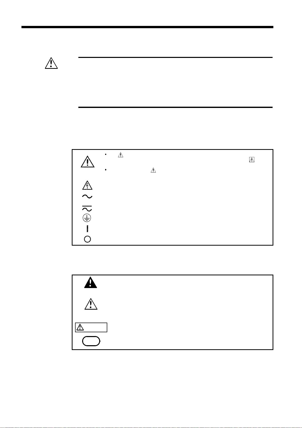
Safety Symbols
The symbol printed on the product indicates that the user should
refer to a corresponding topic in the manual (marked with the
symbol) before using the relevant function.
In the manual, the symbol indicates particularly important
information that the user should read before using the product.
Indicates that dangerous voltage may be present at this terminal.
Indicates a fuse.
Indicates AC (Alternating Current).
Indicates a protective conductor terminal.
Indicates the ON side of the power switch.
Indicates the OFF side of the power switch.
The following symbols in this manual indicate the relative importance of
cautions and warnings.
Indicates that incorrect operation presents an extreme hazard that
DANGER
WARNING
CAUTION
could result in serious injury or death to the user.
Indicates that incorrect operation presents a significant hazard that
could result in serious injury or death to the user.
Indicates that incorrect operation presents a possibility of injury to
the user or damage to the product.
NOTE
______________________________________________________________________________________________
Find Quality Products Online at: sales@GlobalTestSupply.com
Advisory items related to performance or correct operation of the
product.
www.GlobalTestSupply.com

_____________________________________________________________________________________________
iii
Overvoltage Categories
This product conforms to the safety requirements for CAT I measurement
products.
To ensure safe operation of measurement products, IEC 60664 establishes
safety standards for various electrical environments, categorized as CAT I to
CAT IV, and called overvoltage categories. These are defined as follows.
CAT I
Secondary electrical circuits connected to an
AC electrical outlet through a transformer or
similar device.
CAT II
CAT III
CAT IV
Primary electrical circuits in equipment connected to
an AC electrical outlet by a power cord (portable
tools, household appliances, etc.)
Primary electrical circuits of heavy equipment (fixed
installations) connected directly to the distribution
panel, and feeders from the distribution panel to
outlets.
The circuit from the service drop to the service
entrance, and to the power meter and primary
overcurrent protection device (distribution panel).
Higher-numbered categories correspond to electrical environments with
greater momentary energy, so a measurement product designed for CAT III
environments can endure greater momentary energy than one designed for
CAT II. Using a measurement product in an environment designated with a
higher-numbered category than that for which the product is rated could
result in a severe accident, and must be carefully avoided.
______________________________________________________________________________________________
Find Quality Products Online at: sales@GlobalTestSupply.com
www.GlobalTestSupply.com
iv
_____________________________________________________________________________________________
Notes on Use
Follow these precautions to ensure safe operation and to obtain the full
benefits of the various functions.
To avoid electric shock, do not remove the product's case. The
DANGER
WARNING
internal components of the product carry high voltages and may
become very hot during operation.
The vinyl shield on the 9615-01 H.V. TEST LEAD alligator clip is not
high voltage insulated. Do not touch when high voltage is applied.
To avoid electric shock, do not allow the product to get wet, and do
not use it when your hands are wet.
To avoid electric shock, be sure to connect the protective ground
terminal to a grounded conductor.
Before turning the product on, make sure the source voltage matches
that indicated on the product's power connector. Connection to an
improper supply voltage may damage the product and present an
electrical hazard.
CAUTION
NOTE
To avoid damaging the power cord, grasp the plug, not the cord, when
unplugging the cord from the power outlet.
To avoid damaging the 9615-01, 9615-02 H.V. TEST LEAD, do not kink or
pull on the leads.
For safety reasons, when taking measurements, only use the 9615-01,
9615-02 H.V. TEST LEAD provided with the product.
To avoid damage to the product, protect it from vibration or shock during
transport and handling, and be especially careful to avoid dropping.
Do not use the product near a device that generates a strong electromagnetic field or
electrostatic charge, as these may cause erroneous measurements.
______________________________________________________________________________________________
Find Quality Products Online at: sales@GlobalTestSupply.com
www.GlobalTestSupply.com

_____________________________________________________________________________________________
v
Chapter Summary
Chapter 1 Overview
Describes an overview, features, and the names and functions of the parts of
the product.
Chapter 2 Testing Arrangements
Describes particulars of testing arrangements.
Chapter 3 Control Signal and Control Method
Describes the control signal and control method when using a device other
than the 3153 as the master unit.
Chapter 4 Specifications
Contains the unit specifications such as the general specifications,
measurement accuracy, etc. of the unit.
Chapter 5 Maintenance and Inspection
Covers the maintenance, inspection and ultimate disposal.
______________________________________________________________________________________________
Find Quality Products Online at: sales@GlobalTestSupply.com
www.GlobalTestSupply.com

_____________________________________________________________________________________________
1
Chapter 1
Overview
1.1 Product Introduction
The 3930 is a passive auxiliary tester that is connected to and controlled by
a master unit (the 3153 AUTOMATIC INSULATION/WITHSTANDING
HiTESTER, or a sequencer). The 3930 cannot operate on a standalone
basis.
This auxiliary tester is designed to safely permit testing of multiple locations
with a minimum of connection changes. This unit can output from any
channel high voltage that is input through a high-voltage input cord simply
by turning the internal high-voltage relays on and off. Up to four of these
units can be connected to a single master unit, with each unit identified by a
unique ID.
______________________________________________________________________________________________
Find Quality Products Online at: sales@GlobalTestSupply.com
www.GlobalTestSupply.com
1.1 Product Introduction

2
_____________________________________________________________________________________________
1.2 Features
In order to prevent electric shock, use voltage to ground that is at or
WARNING
less than the SELV* on the LOW side of the high-voltage input cords.
Although the LOW side of the high-voltage input cords is functionally
insulated from ground, there is no withstand voltage.
*: SELV (separated external low voltage): effective value of 30 V, peak
value of 42.4 V
(1) Direct connection to the 3153
The 3930 can be directly connected to the 3153 AUTOMATIC
INSULATION/WITHSTANDING HiTESTER. Because the 3153 supplies
power to the 3930, no separate power supply is needed.
(2) Single mode and Multi-mode
The 3930 has two operation modes: single mode and multi-mode. Single
mode permits testing of eight channels using the one COM channel and
eight high-output channels. Multi-mode permits testing of four pairs of two
different high-output channels.
(3) Multiple channels
In single mode, the 3930 can test eight channels. In multi-mode, the 3930
can test four channel pairs. In addition, a unique ID can be set for each unit,
allowing a maximum of four 3930s to be connected to a single master unit.
(4) Output channel indicators
The LEDs on the front panel indicate the current mode and the channels that
are being output.
(5) Insulated design
The power supply, the high-voltage inputs and outputs, and the control input
connector signal wires are all functionally insulated.
(6) Signal level from 5 to 24 V
Devices ranging from general logic to a sequencer can be connected by
selecting the supply voltage for the control signal system.
(7) Safe design that avoids duplicate IDs
When multiple 3930s are connected, the unit can detect incorrect (duplicate)
ID settings. When a mistake is detected, all output is shut off.
______________________________________________________________________________________________
Find Quality Products Online at: sales@GlobalTestSupply.com
1.2 Features
www.GlobalTestSupply.com

_____________________________________________________________________________________________
3
1.3 Names and Functions of Parts
1.3.1 Front panel
In order to avoid electric shock, never touch the high-voltage output
WARNING
terminals (high, low), high-voltage test leads or the device being tested
while high voltage is being applied.
POWER switch
Channel output
indicator LEDs
Channel output
indicator LEDs
Mode indicator LED
ID error indicator LED
ID setting dial
Mode setting switch
POWER switch
Mode indicator LED
ID error indicator LED
ID setting dial
Mode setting switch
These LEDs light when the relay for the corresponding channel is on.
(Red: voltage output; green: COM connected)
Indicates the mode that is set by the mode setting switch.
(Red: single mode; green: multi-mode)
Lights red if a duplicate ID is detected when multiple 3930s are
connected.
Sets the ID of this 3930.
Sets the mode of this 3930 (single mode or multi-mode).
Turns on the 3930.
______________________________________________________________________________________________
Find Quality Products Online at: sales@GlobalTestSupply.com
www.GlobalTestSupply.com
1.3 Names and Functions of Parts
4
_____________________________________________________________________________________________
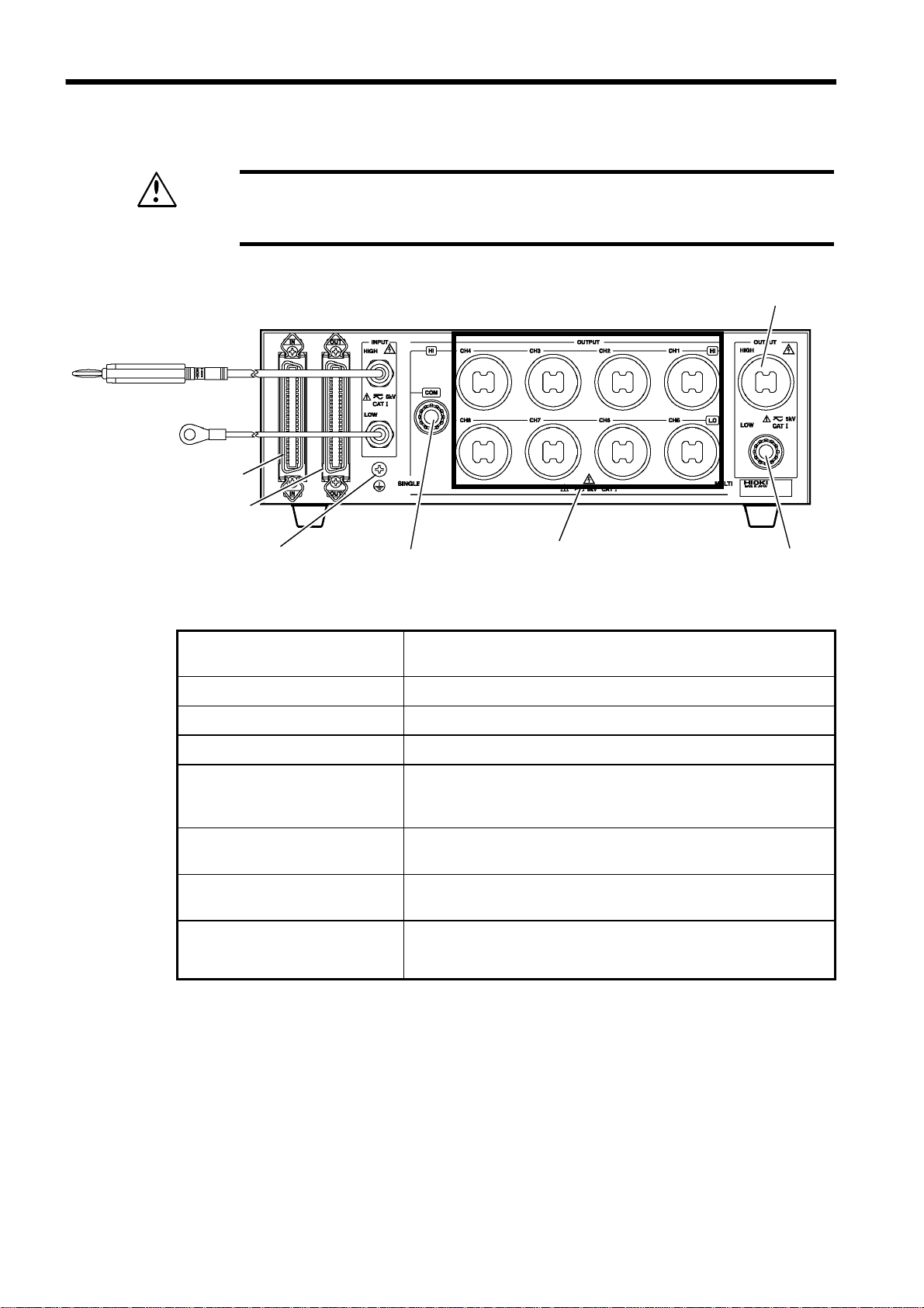
1.3.2 Rear panel
In order to avoid electric shock, never touch the high-voltage output
WARNING
High-voltage input cord
Control input connector
terminals (high, low), high-voltage test leads or the device being tested
while high voltage is being applied.
High voltage output terminal
when multiple units are connected
Control output connector
Ground terminal
High-voltage input cord
Control input connector
Control output connector
Ground terminal
COM terminal
High voltage output terminals
for measurement
COM terminal when multiple
units are connected
High voltage output terminal
when multiple units are
connected
COM terminal
High voltage output
terminals for measurement
COM terminal
when multiple units are
connected
This cord is used to input high voltage. Use voltage to
ground that is at or less than the SELV* on the LOW side.
This connector is used to control the 3930.
This connector is used to connect multiple 3930s.
This terminal grounds the 3930 case.
This terminal is connected to the LOW side of the highvoltage input cord. In single mode, this terminal is the
LOW side common input.
These are the output terminals that are connected to the
device being measured.
This is the LOW side output terminal when multiple 3930s
are connected.
This is the high-voltage output terminal when multiple
3930s are connected.
*: SELV (separated external low voltage): effective value of 30 V, peak
value of 42.4 V
______________________________________________________________________________________________
Find Quality Products Online at: sales@GlobalTestSupply.com
1.3 Names and Functions of Parts
www.GlobalTestSupply.com
 Loading...