

Page 1

取扱説明書
INSTRUCTION MANUAL
3909
インタフェースパック
INTERFACE PACK
Page 2

Page 3

――――――――――――――――――――――――――
目次 1
目 次
はじめに
安全について
点検
ご使用にあたっての注意
第 1 章 概要
1.1 TEMP ユーティリティーの概要
1.2 TEMP ユーティリティーの一般仕様
1.3 TEMP ユーティリティーの機能仕様
第 2 章 ご使用になる前に
第 3 章 接続方法
第 4 章 使用方法
4.1 パソコンの接続
4.2 インストールの方法
4.3 メモリデータの読込み(3443 のみ)
4.3.1 基本的な使い方
4.4 データ処理
4.5 ファイルの保存、読み込み、
および印刷
4.6 リアルタイム測定(3444、3445)
4.6.1 リアルタイム測定の方法
4.6.2 モニタ測定の方法
4.6.3 データ処理
4.6.4 ファイルの保存
または読込みと印刷
4.6.5 本体の設定
4.6.6 グラフ表示
第 5 章 プリンタの使用(3443のみ)
5.1 プリンタの接続
5.2 温度計のメモリデータを印字する
1
1
2
3
5
5
5
6
7
9
11
11
12
12
12
15
17
19
20
25
25
27
28
30
37
37
38
―――――――――――――――――――――――
Page 4

目次 2
――――――――――――――――――――――――――
第 6 章 レコーダとの接続(3444、3445)
6.1 アナログ電圧出力スケールを設定する
第 7 章 保守・サービス
7.1 故障かなと思ったら
41
42
45
46
―――――――――――――――――――――――
Page 5

――――――――――――――――――――――――――
はじめに
このたびは、
いただき、誠にありがとうございます。この製品を十分に活
用いただき、末長くご使用いただくためにも、取扱説明書は
ていねいに扱い、いつも手元に置いてご使用ください。
・登録商標について
・
Windows
・
Excel
・その他の製品名は各社の商標または登録商標です。
HIOKI3909
は米国マイクロソフト社の登録商標です。
は米国マイクロソフト社の登録商標です。
インタフェースパック をご選定
安全について
この測定器は、測定方法を間違えると人身事故や
機器の故障につながる可能性があります。取扱説
警告
この取扱説明書には本器を安全に操作し、安全な状態に保つ
のに要する情報や注意事項が記載されています。本器を使用
する前に下記の安全に関する事項をよくお読みください。
明書を熟読し、十分に内容を理解してから操作し
てください。万一事故があっても、弊社製品が原因
である場合以外は責任を負いかねます。
1
○安全記号
使用者は、この取扱説明書の中の マークのある
ところは必ず説明を読み、注意する必要があるこ
とを示します。
―――――――――――――――――――――――
Page 6

2
――――――――――――――――――――――――――
本取扱説明書の注意事項には重要度に応じて以下の表記をし
ています。
警告
注意
注記
○使用前の確認
・使用前には、過酷な保存や輸送による故障がないか、点検と
動作確認をしてから使用してください。故障を確認した場合
は、お買上店(代理店)か最寄りの営業所にご連絡ください。
操作や取扱いを誤ると、使用者が死亡または重傷
につながる可能性があることを意味します。
操作や取扱いを誤ると、使用者が傷害を負う場合、
または機器を損傷する可能性があることを意味し
ます。
製品性能および操作上でのアドバイス的なことを
意味します。
点検
本器がお手元に届きましたら、輸送中において異常または破
損がないか点検してからご使用ください。特に付属品および
端子類に注意してください。
万一、破損あるいは仕様どおり動作しない場合は、お買上店
(代理店)か最寄りの営業所にご連絡ください。
―――――――――――――――――――――――
Page 7

――――――――――――――――――――――――――
ご使用にあたっての注意
本器を安全にご使用いただくために、また機能を十二分に活
用いただくために、下記の注意事項をお守りください。
・
・
・
・弊社はいかなる場合においてもお客様が
・
ユーティリティー"は日置電機株式会社の著作物で
"TEMP
す。
放射温度計の制御またはデータを処理する以外 の目的で、
ユーティリティー"を一部または全部を複製、複写、
"TEMP
改変する事は法律で禁じられております。
ユーティリティー"は改良のため予告なく変更、バー
"TEMP
ジョンアップすることがあります。
ユーティリティー"を引用し書籍を刊行する場合、弊
"TEMP
社による事前の承諾が必要です。また、「
用はできません。
ティー"を使用した運用結果に関していっさいの責任を負う
ものではありません。
ユーティリティー"の最新バージョンは、弊社ホーム
"TEMP
ページからダウンロードできます。
http://www.hioki.com/
HIOKI
"TEMP
」の商標の使
ユーティリ
3
―――――――――――――――――――――――
Page 8

4
――――――――――――――――――――――――――
CD-R の取り扱いについて
・ ディスクに指紋などの汚れを付けないように
するため、また印刷がかすれないようにするた
め、お取り扱いの際は必ずディスクの縁を持つ
ようにしてください。
・ディスクの記録面には決して手を触れないよう
にしてください。また堅いものの上に直接置か
ないようにしてください。
・ディスクのレーベル表示が消える可能性があり
ますので、ディスクを揮発性アルコールや水に
ぬらさないようにしてください。
・ディスクのレーベル面に文字を記入するとき
は、先がフェルトの油性ペンをご使用ください。
ディスクを傷つけ記録内容を破損する危険性が
注意
ありますので、ボールペンやその他の先の堅い
ペンは使用しないでください。また粘着性ラベ
ルも使用しないでください。
・ディスクがゆがんだり記録内容が破損する危険
性がありますので、直射日光や高温多湿の環境
にディスクをさらさないでください。
・ディスクのシミやホコリ、指紋などを取り除く
場合には、柔らかくて乾いた布またはCDクリ
ーナーをお使いください。常に内側から外側に
向けてぬぐうようにし、決して輪を描くように
はふかないでください。また、研磨剤や溶剤系
クリーナーは使用しないでください。
・この CD-R のご使用にあたってのコンピュータ
システム上のトラブル、および製品の購入に際
してのトラブルについて、弊社は一切の責任を
負いません。
―――――――――――――――――――――――
Page 9

――――――――――――――――――――――――――
第1章 概要
1.1 TEMP ユーティリティーの概要
ユーティリティー"はパソコンを使って放射温度計の
"TEMP
データ処理、または操作をするソフトウェアです。
本文中で""で囲まれているものは画面やボタン等の名称を
表します。
また、[]はメニュー項目を示します。
1.2 TEMP ユーティリティーの一般仕様
:
メディア
対応測定器:3443, 3444, 3445
●動作環境
本体
画面表示
ハードディスク
CD-R 1
枚
放射温度ハイテスタ
:
Windows2000、XP、Vista
パーソナルコンピュータ
:解像度
:空き容量
800×600
ドット、16色以上
4MByte
以上
が動作する
5
―――――――――――――――――――――――
第1章 概要
Page 10
6
、
――――――――――――――――――――――――――
1.3 TEMP ユーティリティーの機能仕様
●フィールドタイプ用(3443 に対応)
最大データ数
ファイル操作
印刷
画面
統計
測定値判定
通信
●ラボタイプ用(3444、3445 に対応)
最大データ数
ファイル操作
印刷
画面
グラフ表示機能
編集
統計
通信
データ
ファイル読み込み、ファイル書き込み
形式
)
データ表印刷A3、A4、B4、B5用紙縦横に
対応
データ
定画面
最大値、最小値、平均値
上限値、下限値との比較判定
RS-232C
射温度計の測定設定等が可能
32000
ファイル読み込み、ファイル書き込み
形式
)
データ表印刷、グラフ印刷A3、A4、B4、
用紙縦横に対応
データCH一覧表、データ表、グラフ画面
リアルタイム測定画面、その他各種設定画
面
8CH
およびズーム可能、2本のカーソル表示、カ
ーソルデータ表示、カーソル間データ演算
グラフ画面をクリップボードへコピー
最大値、最小値、平均値
RS-232C
度計の測定設定等が可能
、合計
No.64
一覧表、データ表、その他各種設
No.
より、メモリデータ読み込み、放
データ×
同時表示 時間軸、温度軸スケール変更
8CH
より、リアルタイム測定、放射温
130
個
(CSV
(CSV
B5
―――――――――――――――――――――――
第1章 概要
Page 11

――――――――――――――――――――――――――
第2章 ご使用になる前に
●フェライトコアの取付け方
電磁波の影響を防ぐため、各ケーブルにフェライトコアを取
り付けることをお薦めします。
注記 CE マーキングの取得は、ケーブルにフェライトコアを
取り付けた状態で行っています。
・モジューラーケーブル
フェライトコア
3443,3444,
3445 側
7
3443,3444,3445
にして取り付けてください。
・その他のケーブル
アナログ出力ケーブルまたはパソコンケーブルについてもモ
ジューラーケーブルと同様にフェライトコア(大)にケーブ
ルを2重巻にし、拡張ボックス側にできるだけ近い部分に取
り付けてください。
―――――――――――――――――――――――
にできるだけ近い部分にケーブルを2重巻
第2章 ご使用になる前に
Page 12

8
――――――――――――――――――――――――――
―――――――――――――――――――――――
第2章 ご使用になる前に
Page 13

――――――――――――――――――――――――――
第3章 接続方法
●3443(フィールドタイプ)
3443
RS-232C
ケーブル(ストレート)
またはクロスプリンタ仕様に
よる
プリンタ
●3444、3445(ラボタイプ)
3444、3445
アナログ電圧出力ケーブル
モジューラケーブル
RS-232C
(クロス)
モジューラケーブル
AC
アダプタ(別売)
拡張ボックス
パソコンまたは
プリンタを接続
ケーブル
AC
アダプタ(別売)
拡張ボックス
パソコン
9
レコーダ
RS-232C
ケーブル(クロス)
―――――――――――――――――――――――
パソコン
第3章 接続方法
Page 14

10
――――――――――――――――――――――――――
・RS-232C ケーブルおよび プリンタケーブルは
市販品をお求めください。
注意
・RS-232C ケーブルのクロ ス接続とストレート
接続のタイプを間違えて使用すると故障の原因
となります。接続前に十分確認してください。
―――――――――――――――――――――――
第3章 接続方法
Page 15

――――――――――――――――――――――――――
11
第4章 使用方法
4.1 パソコンの接続
拡張ボックスの
ポートとを
COM
RS-232C
9 ピンオスコネクタ
と書かれたコネクタとパソコンの
RS-232C
ケーブルで接続します。
RS-232C
に購入することができます。
RS-232C
があります。拡張ボックスとパソコンと放射温度計の接続に
はクロス接続の
ないよう注意してください。
―――――――――――――――――――――――
ケーブルは、パソコンを取り扱っているお店で普通
ケーブルは、ストレート接続とクロス接続の2種類
RS-232C
ケーブルを使用しますので、間違え
第4章 使用方法
Page 16

12
――――――――――――――――――――――――――
4.2 インストールの方法 Setup.exe を実行中に停電したり、コンピュータ
注意
の電源を切るとハードディスクの内容が破壊され
る可能性があります。
1. TE MP
2. TE MP
3. [¥Japanese¥Setup.exe]
4.
5.
4.3 メモリデータの読込み(3443 のみ)
4.3.1 基本的な使い方
1.[メモリデータ読み込み]を起動させる。
①スタート→プログラム
―――――――――――――――――――――――
第4章 使用方法
ユーティリティー
ます。
ユーティリティー
イブを選択します。
画面の指示に従って
ル作業を行ってください。
インストールが正しく行われたことを確認してください。
→
ィーを選択します。
TEMP
ー[スタートメニュー]画
面が表示されます。
ユーティリテ
TEMP
ユーティリティ
CD-RをCD-ROM
が入っている
CD-R
を実行します。
ユーティリティーのインストー
TEMP
ドライブに入れ
CD-ROM
ドラ
Page 17

――――――――――――――――――――――――――
②
メモリデータ読み込み
メモリ読み込みが起動します。
2.通信の設定を行う。
通信ができるようにするために、
す。
[設定]−[
COM1からCOM4
計を接続した
放射温度計を接続した
通常は
通信設定]を選択します。
COM
COM1かCOM2
ボタンを押します。
ポートの選択をしま
COM
まで選択することができるので、放射温度
ポートを選択してください。
ポートがどれか分からない場合、
COM
のどちらかを選びます。
13
―――――――――――――――――――――――
第4章 使用方法
Page 18

14
――――――――――――――――――――――――――
3.通信の確認を行う。
放射温度計とパソコンと
の接続が完了し通信設定
も終わりましたら、通信動
作の確認をします。
[設定]−[
ーを選択します。指示に
従って操作すると、通信動
作が確認できます。
正しく接続されていない場合は、
して再度確認してください。
4.温度計のメモリデータをパソコンへ読み込む
メモリデータ読み込み
に転送されるのを確認します。
注記 パソコン側から、温度計のメモリデータをすべて消去す
接続確認]メニュ
ポートの選択を変更
COM
ボタンを押してメモリデータ一覧表
ることができます。[メモリデータ]−[メモリデータクリ
ア]を選択します。
5.終了する。
ボタンを押してください。
終了
ユーティリティーが終了します。
TEMP
―――――――――――――――――――――――
第4章 使用方法
Page 19

No.
15
ごとに
測定者
――――――――――――――――――――――――――
4.4 データ処理
●メモリデータ一覧表
のメモリデータはデータ
3443
れています。各データ
がメモリできます。データ
メモリデータはすべてのデータ
の合計で
メモリデータ一覧表ではメモリデータの各データ
測定開始・終了時刻、メモリデータ数、最大値、最小値、平
均値、測定者を表示します。
No.
○測定データにタイトルと測定者を記入する
メモリデータ一覧表でタイトルと測定者を記入することがで
きます。
測定内容としてのタイトルと、測定データの責任者としての
測定者を入力することで測定データの信頼性が高まります。
忘れないうちに記入することをお薦めします。
入力方法は、メモリデータ一覧表で、各データ
または測定者の項目をダブルクリックするとテキスト入力状
態になりますので、そこで入力を行ってリターンキーを押し
てください。
個までメモリできます。
130
開始時刻
タイトル
No.には1
終了時刻
―――――――――――――――――――――――
というブロックで管理さ
No.
〜最大
130
No.は1〜64
まで使用可能です。
のすべてのメモリデータ
No.
データ数
個までのデータ
最大・最小
平均値
のタイトル
No.
第4章 使用方法
Page 20

16
――――――――――――――――――――――――――
●データ表の表示
各データ
は、データ表を表示するこ
とで見ることができます。
の測定データ
No.
最小値(赤色)
最大値(青色)
メモリデータ
[
を選ぶことでデータ表の
表示の
ON/OFF
えられます。
○表示するデータNo.の選択
メモリデータ一覧表で表示したいデータ
クします。
選択された
ます。
データ表には選択されたデータ
ます。
また、データ表には上下のボタンが付いていて、
を押すと前のデータ
のデータ表の表示になります。
データ表
]-[
が切り換
は一覧表の一番左の番号の部分の色が変わり
No.
]
No.、▼
No.
の測定データが表示され
No.
ボタンを押すと次のデータ
のセルをクリッ
ボタン
▲
No.
―――――――――――――――――――――――
第4章 使用方法
Page 21

――――――――――――――――――――――――――
○判定機能
データ表には上限値、下限
値を入力する部分があり、
ここに数値を入力すると
測定データの判定ができ
ます。判定結果はデータ
表の判定の列に表示され
ます。
:測定値が上限値を超
Hi
えたとき
:測定値が下限値未満
Lo
のとき
範囲内だったときは何も
表示されません。
上限値、下限値の入力部に
能は無視されます。両方に
となります。
4.5 ファイルの保存、読み込み、および印刷
●測定データのファイルへの保存
すべてのデータ
に保存されます。
ファイル
[
名を入力するかファイルを選択して
押すと保存されます。
ファイルから読み込んだデータで、タイトルや測定者を変更
して、ファイルを更新したい場合には、[ファイル
存]を選んでください。
ファイルは
保存されます。
データ数が多い場合には保存に時間がかかることがあります。
No.
名前を付けて保存]を選んでください。ファイル
]-[
形式(カンマ区切りのテキストファイル)で
CSV
"-"
"-"
の測定データがまとめて1つのファイル
―――――――――――――――――――――――
判定値
を入力するとそれぞれの判定機
を入力すると判定機能は
ファイル保存
]-[
第4章 使用方法
17
OFF
ボタンを
上書き保
Page 22

18
――――――――――――――――――――――――――
●測定データのファイルからの読み込み
ファイル
[
ボタンを押すと読み込みが行われます。
開く
●印刷
すべてのデータ
ファイル
[
用紙選択などを設定します。
ファイル
[
ますので必要な設定をしてから印刷を行ってください。
印刷ボタンを押しても印刷できます。
注記 一覧表やそれぞれのデータ No.のデータのみを印刷する
ことはできません。
●本体時計の設定
本体時計設定]を選
[設定]-[
択します。
時刻を設定して
ンを押すと、本体へデータ
が送信され時計が設定さ
れます。
●本体設定
放射温度計本体に送信す
る測定設定を行います。
本体設定]を選択し
[設定]-[
ます。
を選んでください。ファイル名を選択して
]-[開く]
の測定データがまとめて印刷されます。
No.
用紙設定]を選んでください。プリンタの選択や
]-[
を選んでください。印刷のダイアログが出
]-[印刷]
ボタ
OK
放射率設定
放射率の設定を直接数値で入力するか、リストから選択して
設定します。
設定範囲は
編集
―――――――――――――――――――――――
第4章 使用方法
0.10〜1.00
ボタンを押すとリストの内容の編集ができます。
までで
分解能です。
0.01
Page 23

――――――――――――――――――――――――――
放射率リストの編集画面
放射率のリストは全部で10個まで登録できます。
追加する場合
リスト上にて追加したい
位置をクリックします。
材質、放射率の入力部分に
追加したい内容を書き込
んで
追加されます。
削除する場合
リスト上にて削除したい項目をクリックします。
削除
変更する場合
リスト上にて変更したい項目をクリックします。
材質、放射率の入力部分に変更したい内容を書き込んで
変更
4.6 リアルタイム測定(3444、3445)
リアルタイム測定では、以下のような機能があります。
・リアルタイム測定
放射温度計と
をパソコンに読み込んでメモリします。
・8CH データ表表示
リアルタイム測定による測定値データや、ファイルから読み
込んだ測定データを最高
表示することができます。
・グラフ表示
読み込んだデータを最高
できます。
時間軸、温度軸のスケール変更、任意のズームが可能です。
カーソルによる値の読み出し、カーソル間の統計演算ができ
ます。
―――――――――――――――――――――――
ボタンを押すと
追加
ボタンを押すと削除されます。
ボタンを押すと変更されます。
RS-232C
で接続し、リアルタイムに測定データ
までそれぞれデータ表として
8CH
同時にグラフ表示することが
8CH
第4章 使用方法
19
Page 24

20
――――――――――――――――――――――――――
4.6.1 リアルタイム測定の方法
リアルタイム測定は、放射温度計とパソコンを
続して、リアルタイムに測定データを読み込んでパソコンに
メモリしていく機能です。
1.[リアルタイム測定]を起動させる。
①スタート→プログラム→
ユーティリティー
TEMP
を選択します。
ユーティリティー
TEMP
スタートメニュー]画面が
[
表示されます。
②
リアルタイム測定
リアルタイム測定が起動します。
ボタンを押します。
RS-232C
で接
―――――――――――――――――――――――
第4章 使用方法
Page 25

――――――――――――――――――――――――――
2.通信の設定を行う。
通信ができるようにするためには、
ます。
[設定]−[
択することができます。
放射温度計を接続した
通常は
3.通信の確認を行う。
放射温度計とパソコンとの接
続が完了し、通信設定も終了
したら、通信動作の確認をし
ます。
[設定]−[
を選択します。指示に従って
操作をすると、通信動作が確
認できます。
通信設定]を選択します。
ポートがどれか分からない場合、
COM
COM1かCOM2
接続確認]メニュー
のどちらかを選びます。
COM
COM1
から
ポートの選択をし
COM4
21
まで選
―――――――――――――――――――――――
第4章 使用方法
Page 26
22
――――――――――――――――――――――――――
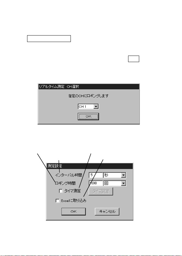
4.温度計の測定データをパソコンへ読み込む。
①メモリするCHを選択する。
リアルタイム測定
測定]を選択すると、「リアルタイム測定CH選択」画面が表示
されます。
測定データを読み込みたい
押します。
選択されたCHは、一覧表の一番左のCH番号の部分の色が
変ります。(リアルタイム測定CH選択に変更)
②リアルタイム測定の条件を設定する。
「測定設定」の画面が出ますので、下記に従って設定してくだ
さい。
ロギング時間
インターバル時間
ボタンを押すか、[測定]−[リアルタイム
を選択し、
CH No.
タイマ測定
Excel に取り込み
OK
ボタンを
・インターバル設定
インターバル(測定間隔)は、数字と単位の選択で決定しま
す。
―――――――――――――――――――――――
第4章 使用方法
Page 27

――――――――――――――――――――――――――
・ロギング時間設定
ロギング時間(測定時間)も同様に数字と単位の選択で決定
します。また、"回"を選択すると、設定した回数だけ測定しま
す。測定回数は、測定開始時間の一回を含みます。測定時間
の間隔はインターバルで設定した時間となります。
・タイマ測定
タイマ測定を行う場合は、測定時間の設定の"タイマ測定"チ
ェックボックスをチェックします。チェックをONにすると
自動的にタイマ設定画面が出ます。後でタイマの時間を変更
したり確認するときには、タイマ測定チェックボックスの横
の"タイマ設定"ボタンを押すとタイマ設定画面が出ます。
タイマ設定
タイマ設定では、測
定開始時刻と測定終
了時刻または測定時
間を設定することが
できます。
測定終了の時間は、
直接終了時刻を指定
するか測定時間で設
定するか、どちらか
選択してください。
測定時間で"連続"を選択すれば、タイマーでスタートして止
めたいときに手動で止めることができます。
・Excel 取り込みオプション
マイクロソフト社製の表計算ソフト「
してある場合に有効となります。
に取り込み"チェックボックスをONにすると、通常の
"Excel
リアルタイム測定に加えて
とができます。
の表に測定値を取り込むこ
Excel
」をインストール
Excel
23
―――――――――――――――――――――――
第4章 使用方法
Page 28
24
――――――――――――――――――――――――――
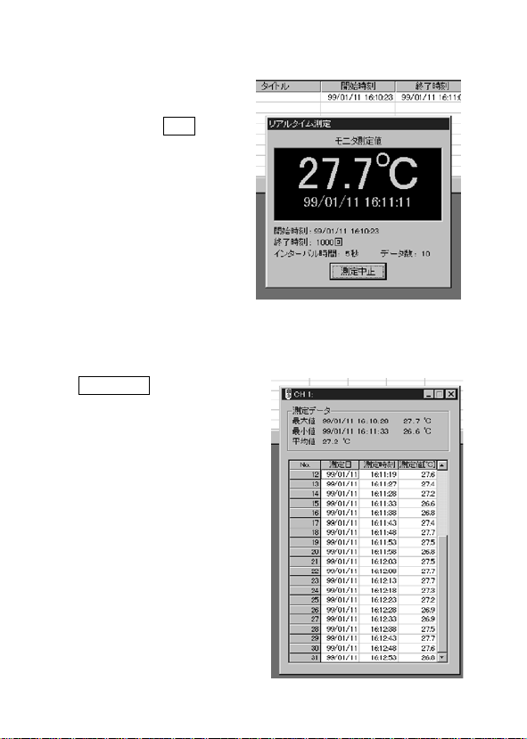
③リアルタイム測定を開始する。
インターバル、ロギング
時間の設定後に「測定設
定」の画面の
を押して、その後の指示
に従って進むと測定が開
始されます。
画面には測定値表示のウ
インドウと、測定値がメ
モリされていくデータ表
が表示されます。
取り込みオプショ
Excel
ンを指定した場合には、
が自動的に起動し新規
Excel
まれていきます。
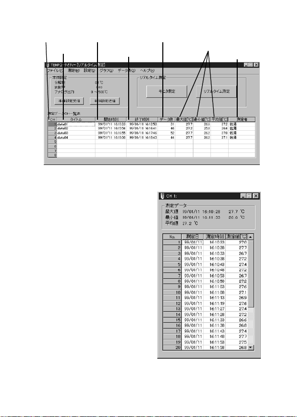
④リアルタイム測定を中止する。
測定中止
とによって、リアルタイム
測定は中止します。中止す
るまでの測定結果は、測定
データCH一覧表およびデ
ータ表に表示されます。
ボタン
OK
ボタンを押すこ
シートにデータが読み込
BOOK
―――――――――――――――――――――――
第4章 使用方法
Page 29

――――――――――――――――――――――――――
4.6.2 モニタ測定の方法
接続の確認も含めてモニタ測定する事をお薦めします。
モニタ測定は、1秒のインターバルで放射温度計から測定デ
ータをリアルタイムに読み込んで、画面に表示のみします。
測定データはメモリされませんので、動作の確認や記録を残
す必要がない場合に、気軽に測定することができます。
モニタ測定を開始するには、
モニタ測定]を選択します。
[測定]-[
4.6.3 データ処理
データの最大値、最小値、平均値を計算し表示します。
・8CH データ表表示
リアルタイム測定による測定値データや、ファイルから読み
込んだ測定データを最高
表示することができます。
・測定データ一覧表
測定データCH一覧表で、タイトルと測定者を記入すること
ができます。
測定内容としてのタ
イトルと、測定データ
の責任者としての測
定者を入力すること
で、測定データの信頼
性が高まります。忘れ
ないうちに記入する
ことをお薦めします。
入力方法は、測定デー
タCH一覧表で、読み
込んだCHのタイト
ルまたは測定者の項
目をダブルクリック
すると、テキスト入力状態になりますので、そこで入力を行
ってリターンキーを押してください。測定データのない
では入力できません。
モニタ測定
まで、それぞれデータ表として
8CH
―――――――――――――――――――――――
ボタンを押すか、
第4章 使用方法
25
CH
Page 30
26
――――――――――――――――――――――――――
No.
タイトル
・データ表
リアルタイム測定による各
の測定データは、データ
CH
表を表示することで見ること
ができます。
データ表]−[(表示したい
[
CH)]
タ表の表示の
り換えられます。同時に最大
8CH
開始時刻
終了時刻
を選択することで、デー
ON/OFF
まで表示できます。
が切
データ数
最大・最小
平均値
測定者
―――――――――――――――――――――――
第4章 使用方法
Page 31

――――――――――――――――――――――――――
4.6.4 ファイルの保存または読込みと印刷 ・測定データのファイルへの保存
ファイル
[
ルの保存CH選択」画面で保存したいCHを選択します。
名前を付けて保存]を選択してください。「ファイ
]-[
27
ファイル名を入力するかファイルを選択して
押すと保存されます。
ファイルから読み込んだデータで、タイトルや測定者を変更
して、ファイルを更新したい場合には、[ファイル
存]を選択してください。
ファイルは
保存されます。
データ数が多い場合、保存に時間が掛かることがあります。
注記 データのないCHを選択して保存しようとした場合は、
エラーになります。
・測定データのファイルからの読み込み
ファイル
[
み」画面で、読み込みたいCHを選択します。
ファイル名を入力するか選択して"開く"ボタンを押すと読み
込みが行われます。
データ数が多い場合、読み込みに時間が掛かることがありま
す。
形式(カンマ区切りのテキストファイル)で
CSV
を選択してください。「ファイルの読み込
]-[開く]
―――――――――――――――――――――――
ボタンを
開く
上書き保
]-[
第4章 使用方法
Page 32

28
――――――――――――――――――――――――――
・印刷
各CHごとの測定データの印刷を行います。
ファイル
[
や用紙選択などを設定します。
印刷したいCHを選択します。
ファイル
[
CH
印刷のダイアログが出ますので、必要な設定をしてから印刷
を行ってください。
一覧表や一度にすべてのCHのデータを印刷することはでき
ません。
・グラフ表示
グラフ
[
リティー-[グラフ]画面が表示されます。
グラフについての詳細は、「
す。
用紙設定]を選択してください。プリンタの選択
]-[
を選択してください。「プリントアウトの
]-[印刷]
選択」画面で印刷したいCHを選択します。
グラフ表示]を選択してください。
]-[
グラフ表示」で説明しま
4.6.6
TEMP
ユーティ
4.6.5 本体の設定
ユーティリティーから
TEMP
射率、およびアナログ電圧出力のスケーリング設定を行うこ
とができます。
設定しても本体へ送信しないと本体は設定されません。
注記
―――――――――――――――――――――――
第4章 使用方法
3444、3445
本体の分解能、放
Page 33

――――――――――――――――――――――――――
●本体設定
放射温度計本体に送信する各値を設定します。
本体設定]を選択すると、本体設定の画面が出ます。
[設定]-[
分解能設定
放射率設定
アナログ出力
スケーリング設定
・分解能設定
測定分解能を、
・放射率設定
放射率の設定を直接数値で入力するか、リストから選択して
設定します。
設定範囲は
ボタンを押すと、リストの内容の編集ができます。
編集
・放射率リストの編集
放射率のリストは全
部で10個まで登録で
きます。
℃または1℃のどちらかに設定します。
0.1
0.10〜1.00
までで
分解能です。
0.01
29
「追加する場合」
リスト上にて追加したい位置をクリックします。
材質、放射率の入力部分に追加したい内容を書き込んで
ボタンを押すと追加されます。
追加
―――――――――――――――――――――――
第4章 使用方法
Page 34

30
――――――――――――――――――――――――――
「削除する場合」
リスト上にて削除したい項目をクリックします。
ボタンを押すと削除されます。
削除
「変更する場合」
リスト上にて変更したい項目をクリックします。
材質、放射率の入力部分に変更したい内容を書き込んで
ボタンを押すと変更されます。
変更
・アナログ出力スケーリング設定
アナログ出力のゼロ出力およびフルスケール出力に相当する
温度を設定します。
-50℃〜500
ただし、ゼロとフルスケールとの差は10℃以上にしてくださ
い。
●本体設定送信
本体設定送信ボタンを押すと、本体へ各設定値を送信します。
●本体設定受信
本体設定受信ボタンを押すと、現在の本体の各設定値を読み
込むことができます。
4.6.6 グラフ表示
TEMP
グラフ表示]を選択してください。グラフ画面が表示されま
-[
す。
℃まで1℃分解能で設定します。
ユーティリティー-[リアルタイム測定]画面の[グラフ
]
―――――――――――――――――――――――
第4章 使用方法
Page 35

――――――――――――――――――――――――――
●時間軸の設定
グラフ
[
自動設定実行]を選択すると、測定データがすべて表示画面
[
に収まるように時間軸を自動的に設定します。
[A-B
表示します。
[1秒]、[5秒]...
選択した時間になります。
時間軸設定]を選択してください。
]-[
間を拡大]を選択すると、カーソルA・Bの間を拡大して
などの時間を選択すると、グラフ上の1目盛が
31
時間軸表示時間の設定が[経過時間]になっていると、測定開
始からの経過時間で時間軸を表示します。
各CH時の測定時刻を見る場合は、CHの
―――――――――――――――――――――――
を選択します。
No.
第4章 使用方法
Page 36

32
――――――――――――――――――――――――――
●温度軸の設定
グラフ
[
設定]を選択して
ください。
自動設定実行]を
[
選択すると、画面
に表示されてい
る時間軸の範囲
で、測定データが
すべて表示画面
に収まるように
温度軸を自動的
に設定します。
表示範囲を指定]を選択すると温度軸の表示範囲を設定する
[
ことができます。
[0.1℃]、[0.5℃]...
が選択した温度になります。
●ズーム
グラフ画面上で
マウスの右ボタ
ンを押して、[時
間軸拡大]、[温度
軸拡大]から拡大
率を選択してく
ださい。
]-[
温度軸
などの温度を選択するとグラフ上の1目盛
―――――――――――――――――――――――
第4章 使用方法
Page 37

――――――――――――――――――――――――――
●任意の範囲のズーム
グラフ画面上でズームしたい箇所を、左ボタンを押しながら
ドラッグして範囲選択します。
選択が終わったらマウスの右ボタン を押し て、[選択範囲拡
大]を選びます。
元に戻すときはグラフ画面上でもう一度マウスの右ボタンを
押して[元のスケール]を選びます。
グラフ
[
作をします。
●波形の表示位置設定
長時間のデータなど
で、現在の表示位置か
ら指定時間後または
カーソルのある位置
をすばやく表示する
ことができます。
波形の時間軸方向の
表示位置を設定しま
す。
グラフ
[
直接時間で指定するか、A・Bカーソルの位置にするか選択
します。
●カーソル
カーソルはA・B2本あり赤色のカーソルがカーソルA、青色
のカーソルがカーソルBです。カーソルはデータがあるとこ
ろだけに移動することができます。
カーソルの情報は画面右側の2つの表に表示されます。
上の表はカーソルの時間と各CHの測定値の読み値および
CH
下の表は
れます。
また、その他のカーソルの機能として次のようなものがあり
ます。
・グラフの時間軸を
・波形の表示位置をカーソルの位置に移動
―――――――――――――――――――――――
選択範囲拡大]、[グラフ
]-[
波形表示位置設定]を選択すると設定画面が出ます。
]-[
間での統計演算値が表示されます。
カーソル間の各CHごとの統計演算値が表示さ
A-B
カーソル間で拡大
A-B
元のスケール]でも同じ動
]-[
第4章 使用方法
33
Page 38

34
――――――――――――――――――――――――――
●カーソルの移動
カーソルの移動
には次の3つの
方法があります。
・カーソルスク
ロールバーを操
作する
・グラフ画面上
で直接カーソル
をドラッグする
・[グラフ
ソル移動]を選ん
でカーソルを指定の時間に移動する
●CH 設定
各CHのグラフ表示の
グラフ
[
カー
]-[
]-[CH設定]
ON/OFF
を選択すると設定画面が出てきます。
色設定
や線の色を指定できます。
各CHの左側のチェックをはずすと表示が
また、右側の"色設定"ボタンを押すと波形の線の色が変更で
きます。
―――――――――――――――――――――――
第4章 使用方法
になります。
OFF
Page 39

――――――――――――――――――――――――――
●グリッドの設定
グラフのグリッド(目盛りの点線)の表示を
す。[グラフ
れます。
●グラフのコピー
[編集]-[
マップデータとしてクリップボードにコピーされます。
クリップボード経由でワープロなど他のアプリケーションに
グラフを貼り付けることができます。
●グラフの印刷
表示されているグラフを印刷することができます。
ファイル
[
や用紙選択などを設定します。
ファイル
[
出ますので必要な設定をしてから印刷を行ってください。
グリッド]を選択すると
]-[
コピー]を選択すると表示されているグラフがビット
用紙設定]を選択してください。プリンタの選択
]-[
を選択してください。印刷のダイアログが
]-[印刷]
ON/OFF
ON/OFF
が切り換えら
35
できま
―――――――――――――――――――――――
第4章 使用方法
Page 40

36
――――――――――――――――――――――――――
―――――――――――――――――――――――
第4章 使用方法
Page 41

――――――――――――――――――――――――――
37
第5章 プリンタの使用
3443
(
5.1 プリンタの接続
3443は、RS-232C
下記の設定が可能なプリンタに接続できます。
●ボーレート
●データビット長 8ビット、スタート、ストップビット、各
ビット
1
●パリティ無し
機能の設定ができる場合は、
CR
み"に設定してください。(
力します)
との接続は、下表の仕様のケーブルを使用してくださ
3443
い。
プリンタ型名(例) プリンタ側コネクタ形状 コネクタ信号 ケーブル仕様
9442
(日置電機製)
DPU‑414
(セイコーインス
ツル製)
BL‑58RS
(三栄電機製)
インタフェース付(
busy
2400bps
"CR無視"
3443は、1
D‑SUB9ピン(メス) 3:データ入力(DATA)
5:グランド(GND)
8:ビジー(BUSY)
D‑SUB9ピン(メス) 3:データ入力(DATA)
5:グランド(GND)
8:ビジー(BUSY)
D‑SUB9ピン(オス) 2:データ入力(DATA)
5:グランド(GND)
7:ビジー(BUSY)
行ごとに
のみ)
信号あり)で、
あるいは"復帰の
を出
CR+LF
9444
D‑SUB9ピン(メス)
←→9ピン(オス)
延長ケーブル
D‑SUB9ピン(メス)
←→9ピン(オス)
延長ケーブル
D‑SUB9ピン(メス)
←→9ピン(メス)
クロスケーブル
注記
RS-232C
インタフェースの無いプリ ンタ は使 用で きま
せん。
―――――――――――――――――――――――
第5章 プリンタの使用(
3443
のみ)
Page 42

38
――――――――――――――――――――――――――
○接続方法
3443
モジューラケーブル
拡張
ボックス
プリンタ
RS-232C
接続ーブル
5.2 温度計のメモリデータを印字する
① プリンタと温度計が本体が前の
ページの図のように接続されて
いるのを確認した後、プリンタの
電源と温度計本体の電源を入れ
ます。
キーを一瞬押すと本体の
MEAS
電源が入ります。
プリンタ印字中以外は操作を何
もしないで約15秒間たつと、自動
的に電源が切れます。
②
キーを一回押すとデータの印
P
字を開始します。
が点滅します。
Prn
―――――――――――――――――――――――
第5章 プリンタの使用(
3443
のみ)
Page 43

――――――――――――――――――――――――――
39
③プリンタにメモリデータが印字されます。本体にメモリされ
ているすべてのメモリデータを印字します。
―――――――――――――――――――――――
第5章 プリンタの使用(
3443
のみ)
Page 44

40
――――――――――――――――――――――――――
―――――――――――――――――――――――
第5章 プリンタの使用(
3443
のみ)
Page 45

――――――――――――――――――――――――――
41
第6章 レコーダとの接続
3444、3445
(
)
3444、3445
グ出力ケーブルを使用し、レコーダと接続することによって、
測定値の変化を記録することができます。アナログ出力は
〜1Vです。また、
定によって、レコーダに記録する温度出力の範囲を設定する
ことができます。
○接続方法
―――――――――――――――――――――――
は、本中継ボックスと接続ケーブルおよびアナロ
3444、3445
3444
アナログ電圧出力
ケーブル
第6章 レコーダとの接続(
のアナログ出力スケールの設
モジューラケーブル
拡張
ボックス
3444、3445
0
)
Page 46

42
――――――――――――――――――――――――――
6.1 アナログ電圧出力スケールを設定する
アナログ電圧出力のゼロ(下限)およびフルスケール(上限)
の温度を設定します。
より、
FS
)を出力します。
V
の設定値が大きい場合は、エラー出力(約
ZERO
1.5
① ZERO を表示する。
の状態から
HOLD
押し、
ZERO
が点滅します。
SET
を表示させます。
キーを数回
M
② ZERO を変更する。
点滅している数字は▽△キーで
変更できます。
③ FS を表示する。
HOLD
の状態から
キーを一回
M
押し、FSを表示させます。
が点滅します。
SET
―――――――――――――――――――――――
第6章 レコーダとの接続(
3444、3445
)
Page 47

――――――――――――――――――――――――――
43
④ FS を変更する。
点滅している数字は▽△キーで
変更できます。
⑤ 設定終了する。
キーを押すと、設定終了
MEAS
です。
―――――――――――――――――――――――
第6章 レコーダとの接続(
3444、3445
)
Page 48

44
――――――――――――――――――――――――――
―――――――――――――――――――――――
第6章 レコーダとの接続(
3444、3445
)
Page 49

――――――――――――――――――――――――――
45
第7章 保守・サービス
・本器の汚れをとるときは、柔らかい布に水か中
性洗剤を少量含ませて、軽くふいてください。ベ
注意
ンジン、アルコール、アセトン、エーテル、ケト
ン、シンナー、ガソリン系を含む洗剤は絶対に使
用しないでください。変形、変色することがあり
ます。
―――――――――――――――――――――――
第7章 保守・サービス
Page 50

46
――――――――――――――――――――――――――
7.1 故障かなと思ったら
症 状 原 因 対 策
パソコンに
データが転
送されない
プリンタに
印字されな
い
本体の電池が消耗また
は装てんされていない
ケーブルが正しく接続
されていない
ポートが正しくな
COM
い
3444、3445
ータ読み込みを選択し
た
プリンタの電源が入っ
ていない
ケーブルが間違っているケーブルの種類を正し
ケーブルが正しく接続
されていない
でメモリデ
新しい電池を装てんし
てください。
コネクタをしっかり接
続してください
パソコン接続用の
接続ケーブルが
232C
クロス接続か確認して
ください
ポートの設定を
COM
別のポート設定にして
ください
[設定]−[
COM1
に設定してください
3444、3445
メモリ機能がないため
メモリデータ読み込み
はできません
プリンタの電源を入れ
てください
いものにする
しっかり接続する
通信設定]で
または
RS-
COM2
にはデータ
―――――――――――――――――――――――
第7章 保守・サービス
Page 51

――――――――――――――――――――――――――
症 状 原 因 対 策
アナログ出
力されない
○サービス
対策後も上記の症状が直らない場合は、故障している可能性
があります。お買上店(代理店)か最寄りの営業所にご連絡
ください。
を接続している
3443
ZERO、FS
かしい
レコーダのレンジが異
なって設定されている
の設定がお
は電圧出力はあ
3443
りません
設定を正しくする
レコーダのレンジを
〜1Vに設定してくだ
さい
47
0
―――――――――――――――――――――――
第7章 保守・サービス
Page 52

48
――――――――――――――――――――――――――
―――――――――――――――――――――――
第7章 保守・サービス
Page 53

保 証 書
形名
3909
本製品は、弊社の厳密なる検査を経て合格した製品をお届けした物です。
万一ご使用中に故障が発生した場合は、お買い求め先にご連絡ください。
本書の記載内容で無償修理をさせていただきます。また、製品の使用による損失について
は、購入金額までの支払いとさせていただきます。なお、保証期間は購入日より1年間で
す。購入日が不明の場合は、製品の製造月から1年を目安とします。ご連絡の際は、本書
を提示してください。また、確度については、明示された確度保証期間によります。
お客様 ご住所: 〒
*お客様へのお願い
・保証書の再発行はいたしませんので、大切に保管してください。
・「形名、製造番号、購入日」およびお客様「ご住所、ご芳名」は恐れ入りますが、お
客様にて記入していただきますようお願いいたします。
1.取扱説明書・本体注意ラベル(刻印を含む)などの注意事項にしたがった正常な使用
状態で保証期間内に故障した場合には、無償修理いたします。また、製造後一定期間
を経過したものおよび部品の生産中止、不測の事態の発生などにより修理不可能と
なった場合は、修理、校正などを辞退する場合がございます。
2.保証期間内でも、次の場合には保証の対象外とさせていただきます。
−1.製品を使用した結果生じる被測定物の、二次的、三次的な損傷、被害
−2.製品の測定結果がもたらす二次的、三次的な損傷、被害
−3.取扱説明書に基づかない不適当な取り扱い、または使用による故障
−4.弊社以外による修理や改造による故障および損傷
−5.取扱説明書に明示されたものを含む、部品の消耗
−6.お買い上げ後の輸送、落下などによる故障および損傷
−7.外観上の変化(筐体のキズなど)
−8.火災、風水害、地震、落雷、電源異常(電圧、周波数など)、戦争・暴動行為、
−9.保証書の提出が無い場合
−10.その他弊社の責任とみなされない故障
−11.特殊な用途(宇宙用機器、航空用機器、原子力用機器、生命に関わる医療用
3.本保証書は日本国内のみ有効です。(
サービス記録
年月日 サービス内容
製造番号 保証期間
ご芳名:
放射能汚染およびその他天災地変などの不可抗力による故障および損傷
機器及び車輌制御機器など)に組み込んで使用する場合で、前もってその旨
を連絡いただかない場合
購入日 年 月より1年間
This warranty is valid only in Japan.)
386-1192
〒
TEL 0268-28-0555
FAX 0268-28-0559
長野県上田市小泉81
06-03
Page 54

外国主要販売ネットワーク
外国代理店については
ご覧いただくか、最寄りの営業所または本社
販売企画課までお問い合わせください。
URL http://www.hioki.com/
HIOKI USA CORPORATION
6 Corporate Drive, Cranbury, NJ 08512 USA
TEL +1-609-409-9109
FAX +1-609-409-9108
E-MAIL hioki@hiokiusa.com
HIOKI
ホームページを
Page 55

HIOKI 3909 インタフェースパック
取扱説明書
発行年月 2008 年 7 月 改訂 3 版
編集 ・ 発行 日置電機株式会社
開発支援課
問合せ先 日置電機株式会社
販売企画課
〒386-1192 長野県上田市小泉 81
TEL: 0268-28-0560
FAX: 0268-28-0569
E-mail: info@hioki.co.jp
URL http://www.hioki.co.jp/
0120-72-0560
Pri nt e d in Jap an 3909A980-03
・本書の内容に関しては万全を期していますが、ご不明な
点や誤りなどお気づきのことがありましたら、本社 販売
企画課または最寄りの営業所までご連絡ください。
・本書は改善のため予告なしに記載事項を変更すること
があります。
・本書には著作権によって保護 され る内容 が含 まれま す。
本書の内容を弊社に無断で転載、複製、改変することは
禁止されています。
Page 56

Page 57

3909
INTERFACE
PACK
INSTRUCTION MANUAL
Page 58

Page 59

Contents
Introduction
Safety Notes
Inspection
Notes on Use
Chapter 1 Summary
1.1 Product Summary of TEMP Utility 1
1.2 General Specifications of TEMP Utility
1.3 TEMP Utility Specifications
Chapter 2 Prior to use 5
Chapter 3 Connecting Method
Chapter 4 Use of Personal Computer
4.1 Connecting the Personal Computer 9
4.2 Installation
4.3 Reading Memory Data
(for 3443(-01) only)
4.3.1 Basic Usage 11
4.4 Data processing 13
4.5 Saving or Reading the File and Printing
4.6 Real-time Measurement
(for 3444(-01) , 3445(01))
4.6.1 Real-time Measurement 20
4.6.2 Monitor Measurement
4.6.3 Data Processing
4.6.4 Saving or Reading of the File and Printing
4.6.5 Main unit setup
4.6.6 Graph display
10
11
17
19
26
27
29
31
34
i
i
iii
iii
1
2
3
7
9
Page 60

Chapter 5 Using the Printer
(for 3443(-01) only)
5.1 Connecting the Printer 41
5.2 Printing Thermometer Memory Data
41
42
Chapter 6 Connecting to a Recorder
(for 3444(-01) , 3445(-01))
6.1 Setting Analog Voltage Output Scale 46
45
Chapter 7 Maintenance and Service 49
7.1 Troubleshooting 50
7.2 Questions and Answers
about Measurement
52
Page 61

―――――――――――――――――――――――――――
Introduction
Thank you for purchasing this Hioki "3909 Interface
Pack." To get the maximum performance from the
unit, please read this manual first, and keep this at
hand.
Registered trademark
・ Windows, Excel and Internet Explorer are the
trademarks of Microsoft Corporation, USA
・ Other product names are the trademarks or registered
trademarks of following companies:
Safety Notes
WARNING
Incorrect measurement procedures could result in
injury or death, as well as damage to the
equipment. Please read this manual carefully and
be sure that you understand its contents before
using the equipment. The manufacturer disclaims
all responsibility for any accident or injury except
that resulting due to defect in its product.
i
This Instruction Manual provides information and
warnings essential for operating this equipment in a
safe manner and for maintaining it in safe operating
condition. Before using this equipment, be sure to
carefully read the following safety notes.
――――――――――――――――――――――――
Introduction
Page 62

ii
―――――――――――――――――――――――――――
Safety symbols
In the manual, this mark indicates
explanations which it is particularly
important that the user read before using
the unit.
The following symbols are used in this Instruction
Manual to indicate the relative importance of
cautions and warnings.
Indicates that incorrect operation
WARNING
presents significant danger of accident
resulting in death or serious injury to the
user.
Indicates that incorrect operation
CAUTION
presents possibility of injury to the user
or damage to the equipment.
Denotes items of advice related to
NOTE
performance of the equipment or to its
correct operation.
Check before use
・
Before using the unit, inspect it and check the
operation to make sure that the unit was not
damaged due to poor storage or transport conditions.
If da mage is found, contact your dealer or Hioki
representative.
――――――――――――――――――――――――
Safety Notes
Page 63

―――――――――――――――――――――――――――
iii
Inspection
When you receive this product, before use, please
check that no abnormality or damage has occurred
during delivery. In particular, be sure to check the
accessories and connectors.
In the unlikely event of damage, or if the unit does not
function according to specification, you should
immediately contact the dealer from whom you bought
the unit, or the nearest HIOKI service facility.
Notes on Use
In order to ensure safe operation and to obtain
maximum performance from the unit, observe the
cautions listed below.
・ "TEMP Utility" is a product of HIOKI E.E.
CORPORATION.
・ The reproduction, copying, or alteration of part or all
of the "TEMP Utility" for any purpose other than
controlling the infrared thermometer or processing
the data is prohibited by law.
・ The "TEMP Utility" may be changed or upgraded by
HIOKI E.E. CORPORATION without notice.
・ When the "TEMP Utility" is to be quoted in a
published work, prior permission from HIOKI E.E.
CORPORATION is required. Further, use of the
trademark "HIOKI" is not permitted.
・ HIOKI E.E. CORPORATION will assume no
――――――――――――――――――――――――
Inspection
Page 64

iv
―――――――――――――――――――――――――――
responsibility for the resulting operation of the
"TEMP Utility" by the user.
・ The latest versi on of the "TEMP Utility" can be
downloaded from our web site. http://www.hioki.com/
CAUTION
Handling the CD
Always hold the disc by the edges, so as not to
・
make fingerprints on the disc or scratch the printing.
Never touch the recorded side of the disc. Do not
・
place the disc directly on anything hard.
Do not wet the disc with volatile alcohol or water, as
・
there is a possibility of the label printing disappearing.
To write on the disc label surface, use a spirit-
・
based felt pen. Do not use a ball-point pen or hardtipped pen, because there is a danger of scratching
the surface and corrupting the data. Do not use
adhesive labels.
Do not expose the disc directly to the sun's rays, or
・
keep it in conditions of high temperature or
humidity, as there is a danger of warping, with
consequent loss of data.
To remove dirt, dust, or fingerprints from the disc,
・
wipe with a dry cloth, or use a CD cleaner. Always
wipe from the inside to the outside, and do no wipe
with circular movements. Never use abrasives or
solvent cleaners.
Hioki shall not be held liable for any problems with
・
a computer system that arises from the use of this
CD, or for any problem related to the purchase of a
Hioki product.
――――――――――――――――――――――――
Notes on Use
Page 65

―――――――――――――――――――――――――――
Chapter 1
Summary
1.1 Product Summary of TEMP Utility
The TEMP utility is software that makes it easy to
proces s or manage 3443(-01), 3444(-01) or 3445(-01)
measurement data on a personal computer.
In the explanations that follow, words enclosed in
quotation marks (" ") are the names of screens or
buttons. Menu items are indicated as words enclosed
in square brackets ([ ]).
1
――――――――――――――――――――――――
Chapter 1 Summary
Page 66

2
y
―――――――――――――――――――――――――――
1.2 General Specifications of TEMP
Utilit
Media: CD (1)
Operating environment
●
Main unit Personal computer th at operates with
Display Resolution 800x600 dots, 16 colors or
Hard disk At leas t 4MB free s pace
Windows2000, WindowXP, or
WindowsVista
more
――――――――――――――――――――――――
Chapter 1 Summary
Page 67

―――――――――――――――――――――――――――
1.3 TEMP Utility Specifications
3443(-01) (Field Type)
●
No. of
maximum data
File operation File readin g, file writing (CVS format)
Printing Data printing. Vertical and horizontal
Screen Data No. table, d ata table, graph screen,
Statistics Maximum, mini mum, average values
Measured
value judgment
Communication Memory data reading and setting of
Data No. 64.
130 total
printing of A3, A4, B4, and B5 pa per
and other various setting screens
Comparison judgment of upper limit and
lower limit
infrared therm ometer measu rement
thr ou gh RS-232C cable a r e possible.
3
――――――――――――――――――――――――
Chapter 1 Summary
Page 68

4
―――――――――――――――――――――――――――
3444(-01) , 3445(-01) (Laboratory Type)
●
No. of
maximum data
File operation File readin g, file writing (CVS format)
Printing Data and graph printing. Vertical and
Screen Da ta C H table, d at a table, gr aph screen,
Graph display
function
Edit Copying gra p h s cre en to clipboard
Statistics Maximum, mini mum, average values
Communication Setting of real-time measuremen t and
32,000 da t a×8CH
horizontal printing of A3, A4, B4, and
B5 paper
real-time measuremen t screen, other
various setting screens
8CH simultaneous display, time axis,
temperat ure axis scale change and
zooming
Two-cursor display, cursor da ta display,
calculation of dat a bet ween cursors
infrared therm ometer measu rement
thr ou gh RS-232C cable a r e possible.
――――――――――――――――――――――――
Chapter 1 Summary
Page 69

―――――――――――――――――――――――――――
Chapter 2
Prior to use
Attaching the ferrite core
●
It is recommended to attach a ferrite core to each
cable to prevent any influence from electromagnetic
waves.
・ CE marking is obtained in the state where the ferrite
NOTE
core is attached to the cable.
Modular cable
・
Ferrite core
To 3443(-01),
3444(-01),
3445(-01)
Wind the cable double, and attach the ferrite core as
close to the 3443(-01), 3444(-01), 3445(-01) side
connector as possible.
5
Other cable
・
Like the modular cable, wind the analog output
cable or personal computer cable double around the
ferrite core (large), and attach it as close to the
expansion box side as possible.
――――――――――――――――――――――――
Chapter 2 Prior to use
Page 70

6
―――――――――――――――――――――――――――
Switching between Fahrenheit and Celsius
●
The 3443-01, 3444-01 and 3445-01 can switch
between Fahrenheit and Celsius displays.
(Refer to Instruction Manual of the 3443-01, 344401 or 3445-01. )
――――――――――――――――――――――――
Chapter 2 Prior to use
Page 71

―――――――――――――――――――――――――――
Chapter 3
Connecting Method
3443(-01) (Field Type)
●
3443(-01)
RS-232C cable(straght
or by the cross cable specification
)
Modular cable
AC adapter(option
Expansion box
Connecting the personal
computer or the printer
)
7
Printer
――――――――――――――――――――――――
RS-232C cable
cross
(
)
Chapter 3 Connecting Method
Personal compute
Page 72

8
―――――――――――――――――――――――――――
3444(-01), 3445(-01) (Laboratory Type)
●
3444(-01)
Analog output cable
Recorder
Modular cable
AC adapter(option
Expansion box
)
RS-232C cable(cross
・ Purchase the RS-232C cable and printer cable from
NOTE
)
Personal computer
a computer shop.
Refer to 3.1 "Connecting the personal computer"
and 4.1 "Connecting the printer."
・ Use of the wrong connection (cross connection vs.
straight connection) with the RS-232C cable will
cause a breakdown.
Carefully confirm prior to connecting the expansion
box.
――――――――――――――――――――――――
Chapter 3 Connecting Method
Page 73

―――――――――――――――――――――――――――
Chapter 4
Use of Personal
Computer
4.1 Connecting the Personal Computer
Connect the RS-232C cable to the connector
indicated as RS-232C on the expansion box and to
the COM port of the personal computer.
9-pin connector (male)
The RS-232C cable has two types of connectors:
straight and cross.
A cross connection RS-232C cable is used to
connect the expansion box to the personal computer.
An RS-232C cable can be obtained at a personal
computer shop. Please purchase the type conforming
to your computer.
9
――――――――――――――――――――――――
Chapter 4 Use of Personal Computer
Page 74

10
―――――――――――――――――――――――――――
4.2 Installation
CAUTION
If a power failure occurs or power to the computer
・
is turned OFF during execution of Setup.exe, data
stored on the hard disk may be damaged.
1. Insert the CD of TEMP Utility to the CD-ROM
drive.
2. Move to the CD-ROM drive in which the CD is
inserted. And run [\English\Setup.exe].
3. Install TEMP Utility in accordance with the
instruction on the screen.
4. Con firm that installation has been completed
correctly.
(The TEMP Utility icon is created in the sub-menu
Programs of the Windows Start menu.)
――――――――――――――――――――――――
Chapter 4 Use of Personal Computer
Page 75

―――――――――――――――――――――――――――
y)
11
4.3 Reading M emory Data (for 3443(-01)
onl
4.3.1 Basic Usage
1. Start up Reading Memory.
① Select Start →
Programs →
TEMP Utility
from the menu
bar.
The TEMP
Utility [Start Up Menu] screen is displayed.
② Select the Read Memory Data button.
Reading of the memory data starts.
2. Set communication.
Select COM port to enable communication.
Select [Settings] - [COM Port] from the menu bar.
Select COM port connected to the infrared
thermometer from COM1 to COM4.
If you do not know which COM port the infrared
thermometer is connected to, select COM1 or
COM2 under normal operation.
――――――――――――――――――――――――
Chapter 4 Use of Personal Computer
Page 76

12
―――――――――――――――――――――――――――
3. Check communication.
When the infrared
thermometer is
connected to the
personal computer
and communication
setup has been
completed, confirm communicability.
Select [Settings] - [Confirm Connection] from the
menu bar. Operation in accordance with the
instructions allows you to check the
communicability.
If the connection is incorrect, change the COM port
and check again.
4. Read thermometer memory data to the personal
computer.
Select the Read Memory Data button to confirm that
the memory data of the 3443(-01) has been
transmitted to the memory data list.
――――――――――――――――――――――――
Chapter 4 Use of Personal Computer
Page 77

―――――――――――――――――――――――――――
・ The memory data of thermometer can be completely
NOTE
13
cleared using the personal computer.
Select [Memory Data] - [Clear Memory Data].
5.Ending
Select the Exit button.
TEMP Utility is closed.
4.4 Data processing
Memory Data Table
●
Memory data for the 3443(-01) is managed
according to blocks named for data No. A maximum
of 130 readings can be stored in the memory for any
data No., and the available data Nos. are 1 to 64.
However, the total number of data readings that can
be stored for all the data Nos. combined is 130.
In the Memory Data Table, the title, start time and
stop time, the number of memory data, maximum
value, minimum value, average value, and the
person taking the measurements are displayed for
each data No. of memory data.
――――――――――――――――――――――――
Chapter 4 Use of Personal Computer
Page 78

14
―――――――――――――――――――――――――――
No.
○
Start time
Title
Number of data
Stop time
Max. / Min. /
Ave. values
Enter the title and the person taking
Person taking
measurements
measurements in the measurement data.
The title and the person taking the measurements
can be entered in the Memory Data Table.
The reliability of the measured data increases when
the title and the measuring person as the responsible
person for the measured data are entered. It is
recommended to enter these items without fail.
Double-click on the Title cell of each data No. or
the Meas. Person cell in the Memory Data Table.
Enter the text, and hit the Return key.
――――――――――――――――――――――――
Chapter 4 Use of Personal Computer
Page 79

―――――――――――――――――――――――――――
)
Data Table
●
The measured data
Max. value (red)
Min. value (blue
15
for each data No.
canbeviewedby
displaying the Data
Table.
When [Memory
Data] - [Data
Table] is selected,
the Data Table
display can be
switched ON/OFF.
Selection of the data No. displayed
○
Click on the cell of the data No. to be displayed in
the Memory Data Table.
When the number is selected, the color of the
number portion at the far left of the table changes.
The measured data of the selected data No. is shown
in the Data Table.
Clicking on the
button in the Data Table displays
▲
the Data Table of the previous data No. and clicking
on the
button displays the Data Table of the next
▼
data No.
――――――――――――――――――――――――
Chapter 4 Use of Personal Computer
Page 80

16
―――――――――――――――――――――――――――
Judgment function
○
The Data Table has
Limit value
a place to enter the
upper limit value
and lower limit
value. By entering
numerical values in
this cell, the
measured data can
be judged.
Judgment results
are displayed in the
Judg. column of the
Data Table.
Hi:Displayed when the measured value is above the
upper limit value.
Lo:Displayed when the measured value is below the
lower limit value.
When the measured value is within the range,
nothing is displayed.
If "-" is entered in the input section of the upper
limit value or lower limit value, the respective
judgment function is ignored. If "-" is entered in
both input cells, the jud gment function is turned
OFF.
――――――――――――――――――――――――
Chapter 4 Use of Personal Computer
Page 81

―――――――――――――――――――――――――――
g
17
4.5 Saving or Reading the File and
Printin
Saving the m easured data in a file
●
The measured data of all data Nos. are collectively
saved in one file.
Select [File] - [Save As] from the menu bar. Enter
the file name or select the file, and select the [Save]
button. The data is saved.
To update the file after having changed the title or
the measuring person with the data read from the
file, select [File] - [Save] from the menu bar. The
file is saved in CSV format (text file punctuated
with commas).
Saving of data with many numbers may take a long
time.
Reading the measured data from the file
●
Select [File] - [Open] from the menu bar. Select the
file name, and select the [Open] button to start
reading.
Printing
●
The measured data of all data No. is collectively
printed.
Select [File] - [Page Setup] from the menu bar. Set
selection of printer and paper size.
Select [File] - [Print] from the menu bar. The
printing dialog box is displayed. Make the necessary
settings, and print.
Selecting the [Print] button also starts printing.
――――――――――――――――――――――――
Chapter 4 Use of Personal Computer
Page 82

18
―――――――――――――――――――――――――――
・ It is not possible to print the data of the Table only
NOTE
or of each data No. individually.
Setting the main unit clock
●
Select [Settings] [Clock Setting].
Set the time, and
select the OK
button. The data is
transmitted to the
main unit, and the time is set.
Main unit setup
●
Measurement
setting for
transmitting to the
infrared
thermometer
Select [Settings] [Settings].
The main unit Settings screen appears.
Emissivity setting
To set the emissivity, enter the numerical value
directly or select from the list.
Setting range is 0.10 to 1.00 with a resolution of
0.01.
Selecting the Edit button allows you to edit the
contents.
Editing the Emissivity lists
A total of ten emissivity lists can be registered.
――――――――――――――――――――――――
Chapter 4 Use of Personal Computer
Page 83

―――――――――――――――――――――――――――
(
))
Adding:
Clickonthe
portion to be added
in the list.
Type in the content
to be added in the
input cell for
material and/or emissivity, and select the [Add]
button.
Deleting:
Click on the item to be deleted from the list.
When the [Delete] button is selected, the it em is
deleted.
Changing:
Click on the item to be changed in the list.
Type in the content to be added in the input cell for
material and/or emissivity, and select the [Edit]
button.
19
4.6 Real-time Measurement
for 3444(-01), 3445(-01
Real-time measurement has the following functions:
Real-time m easurement
・
Connected to the infrared thermometer through RS232C, it reads the measured data to the personal
computer in real time and stores the data in the
memory.
――――――――――――――――――――――――
Chapter 4 Use of Personal Computer
Page 84

20
―――――――――――――――――――――――――――
Displaying 8-channel data table (see p. 20)
・
It is possible to display a maximum of 8 channels of
the real-time measured value data and the measured
data read from the file as data tables.
Graph display (see p. 26)
・
It is possible to display the read data for a
maximum of 8 channels.
Scale for time axis and temperature axis, and
optional zooming are possible.
Reading of the value by cursor and statistic
calculation for cursors are possible.
4.6.1 Real-time Measurement
It is possible to connect the infrared thermometer to
the personal computer using an RS-232C cable, read
the measured data at real time, and store it in your
personal computer.
1. Start [Real Time Measurement].
① Select [Start] -
[Program]-[TEMP
Utility] from the
menu bar.
The [TEMP Utility
(Start Up Menu)]
screen is displayed.
② Select the Real Time Measurement button.
Real-time measurement starts.
――――――――――――――――――――――――
Chapter 4 Use of Personal Computer
Page 85

―――――――――――――――――――――――――――
21
2. Set the communication.
Select COM port to enable communication.
Select [Settings] - [COM Port] from the menu bar.
Select the COM port connected to the infrared
thermometer from COM1 to COM4.
If you do not know which COM port the infrared
thermometer is connected to, select COM1 or
COM2 under normal operation.
――――――――――――――――――――――――
Chapter 4 Use of Personal Computer
Page 86

22
―――――――――――――――――――――――――――
3. Check the communication.
When the infrared
thermometer is
connected to the
personal computer and
communication setup
has been completed,
confirm communicability.
Select [Settings] - [Confirm Connection] from the
menu bar. Operation in accordance with the
instructions allows you to check the
communicability.
If the connection is incorrect, change the COM port
and check again.
4. Read the measured data of the thermometer
into the personal computer.
Select the memory storage CH
①
Press the Real Time Measurement button or select
[Measurement] - [Real Time Measurement]. The
Real Time Measurement Select CH screen is
displayed.
Select the CH No. to which the measured data is
read, and select the OK button.
The color of the selected CH number at the far left
of the list changes.
――――――――――――――――――――――――
Chapter 4 Use of Personal Computer
Page 87

―――――――――――――――――――――――――――
Set the conditions for real-time measurement.
②
23
When the [Measurement Time Settings] screen is
displayed, set up as follows:
Logging Time
Interval Time
Interval setting
・
Timer Measurement
Load To Excel
Decide the interval (measurement interval) by
selecting the figure and unit.
Logging time setting
・
Similarly, decide the logging time (measurement
time) by selecting the figure and unit. When
"Continuous" is selected, measurement continues
until it is stopped manually. When "Continuous" is
selected, the figures cannot be input.
Further, if "Times" is selected, measurement is
performed only for the count that was set.
Measurement count includes the measurement start
time as one time. The measurement time interval is
the time set in Interval Time.
――――――――――――――――――――――――
Chapter 4 Use of Personal Computer
Page 88

24
―――――――――――――――――――――――――――
Timer measurement
・
When performing timer measurement, check the
"Timer Start" check box in the Measurement Time
Settings dialog box. When the check box is
checked, the Timer Settings screen appears
automatically. To change or confirm the timer time
later, select the "Timer Settings" button next to the
"Timer Start" check box. The Timer Settings screen
is displayed.
Timer setting
Measurement
start time and
stop time or
measurement
time can be
set with the
Timer Settings
screen. For
the
measurement
stop time, specify the end time directly or set with
the measurement time. If "Continuous" is selected
for the measurement time, measurement can be
stopped manually when it was started with the
timer.
Option of loading to Excel
・
This option is valid if Microsoft Excel software has
been installed.
When the "Loading to Excel" check box is checked,
the measured value can be read to an Excel table in
addition to normal real-time measurement.
――――――――――――――――――――――――
Chapter 4 Use of Personal Computer
Page 89

―――――――――――――――――――――――――――
Starting real-time measurement
③
25
After setting the
interval and
logging time,
select the OK
button in the
Measurement Time
Settings screen,
and proceed in
accordance with
the instructions to
start measurement.
The screen displays the Real Time Measurement
window for the measured values and the data table
to which the measured values are stored.
When the option of reading to Excel is specified,
Excel starts automatically and the data is read to a
new BOOK sheet.
――――――――――――――――――――――――
Chapter 4 Use of Personal Computer
Page 90

26
―――――――――――――――――――――――――――
Stopping real time-measurement
④
Selecting the Stop
button stops the realtime measurement.
Measurement results
up to this time are
displayed in the
measurement data
CH list and the data
table.
4.6.2 Monitor Measurement
With Monitor measurement, the measured data is
read in real time from the infrared thermometer at
an interval of one second, and displayed on the
screen. As the measured data is not stored, this
measurement can be performed easily if operation
check or recording is not required.
To start Monitor measurement, select the Monitor
Measurement button or select [Measurement] [Monitor Measurement] from the menu bar.
――――――――――――――――――――――――
Chapter 4 Use of Personal Computer
Page 91

―――――――――――――――――――――――――――
27
4.6.3 Data Processing
Making use of the data with your personal computer
The real-time measurement measured value data or
data read from the file are displayed in the Table of
Data CH. It can be displayed also as each data table
up to a maximum of 8 channels.
Also, the maximum value, minimum value, and
average value of the data are calculated and
displayed.
Table of Data CH
●
Enter the title
and person
taking
measurements
in the
measurement
data.
The title and
the person
taking
measurements
can be entered in the Table of Data CH.
The reliability of the measured data increases when
the title and the measuring person as the responsible
person for the measured data are entered. It is
recommended to enter these items without fail.
Double-click on the Title cell of each data No. or
the Meas. Person cell in the Table of Data CH.
Enter the text, and hit the Return key. Entry is not
possible in a CH that has no measured data.
――――――――――――――――――――――――
Chapter 4 Use of Personal Computer
Page 92

28
―――――――――――――――――――――――――――
No.
●
Start time
Title
Data table
Number of data
Stop time
Max. / Min. /
Ave. values
Person taking
measurements
The measured data of
each CH by real-time
measurement can be
viewed when the data
table is displayed.
Selecting [Data table]
- [CH 1] allows you
to switch the data
display ON/OFF. A
maximum of 8
channels can be
displayed at one time.
――――――――――――――――――――――――
Chapter 4 Use of Personal Computer
Page 93

―――――――――――――――――――――――――――
29
4.6.4 Saving or Reading of the File and Printing
Saving the m easured data in the file
●
Select the CH to be saved.
①
Select [File] - [Save As] from the menu bar. Select
the CH to be saved in the [Save File, Select CH]
screen, and select the OK button.
・ If you try to select a CH that contains no d ata, an
NOTE
error message is displayed.
Store the m easured data.
②
Enter the file name in the [Save As] screen or select
the file and select the [Save] button. The data is
saved.
To update the file after having changed the title or
the measuring person with the data read from the
file, select [File] - [Save] from the menu bar. The
file is saved in CSV format (text file punctuated
with commas). Saving of data with many numbers
may take a long time.
――――――――――――――――――――――――
Chapter 4 Use of Personal Computer
Page 94

30
―――――――――――――――――――――――――――
Reading from the file of the measured data
●
Select [File] - [Open] from the menu bar. Select
①
CH to be read on [Open File, Select CH] and
select the [OK] button.
Reading the measured data
②
Enter the file name in the [Open File] screen or
select the file and select the [Open] button. The data
is read.
If the number of data is large, it may take a long
time to load.
Printing
●
Select CH to be printed.
①
The measured data of each CH is printed.
Select [File] - [Page Setup]. Set selection of printer
and paper size.
Select [File] - [Print]. Select CH to be printed in the
[Print Date, Select CH] screen, and select the [OK]
button.
――――――――――――――――――――――――
Chapter 4 Use of Personal Computer
Page 95

―――――――――――――――――――――――――――
Print the m easured data.
②
31
When the print screen is displayed, make the
required setting and start printing.
・ It is not possible to print the data of all CH at one
NOTE
time.
Graph display
●
Select [Graph] - [Graph display]. The TEMP utility
- [Graph] screen is displayed.
For details, see section 4.6.6 Graph Display.
4.6.5 Main unit setup
Resolution, emissivity, and scaling of the analog
voltage output of the 3444(-01), 3445(-01) main
unit can be set from the TEMP Utility.
Main unit setup
●
Each set value to be transmitted to the infrared
thermometer is set.
Select [Settings] - [Settings].
Settings screen appears.
Resolution
Emissivity
Analog Output
Scaling
Resolution
・
Select 0.1℃ or 1℃ (0.1
or 1 ) for measurement
resolution.
――――――――――――――――――――――――
Chapter 4 Use of Personal Computer
Page 96

32
―――――――――――――――――――――――――――
Emissivity
・
To set the emissivity, enter the numerical value
directly or select from the list.
Setting range is 0.10 to 1.00 with a resolution of
0.01.
Selecting the Edit button allows you to edit the
content of the list.
Editing the Emissivity list
A total of ten
emissivity lists
can be
registered.
Adding:
Click on the portion to be added in the list.
Type in the content to be added in the input cell for
material and/or emissivity, and select the [Add]
button.
Deleting:
Click on the item to be deleted from the list.
When the [Delete] button is selected, the it em is
deleted.
Changing:
Click on the item to be changed in the list.
Type in the content to be added in the input cell for
material and/or emissivity, and select the [Edit]
button.
――――――――――――――――――――――――
Chapter 4 Use of Personal Computer
Page 97

―――――――――――――――――――――――――――
Analog output scaling
・
33
Set the temperature corresponding to zero output
and full-scale output of analog output.
Setting range is -50℃ to 500℃ (-67
with 1℃ (1
) resolution.
to 941 )
However, the difference between the zero and fullscale values should be set 10℃ (18
Main unit setup transmission
●
) or more.
Selecting the [Send Settings] button transmits the
set values to the main unit.
Main unit setting reception
●
Selecting the [Receive Settings] button allows you
to read the main units present various set values.
――――――――――――――――――――――――
Chapter 4 Use of Personal Computer
Page 98

34
―――――――――――――――――――――――――――
4.6.6 Graph display
The data read from a maximum of 8 channels can
be displayed in a graph simultaneously.
It is possible to change the scale of the time axis
and the temperature axis, and free zooming.
It is also possible to perform readout of the values
and statistical calculation between cursors.
Select [Graph] - [Graph] from the menu bar to
display the TEMP Utility [Graph] screen.
Before starting real-time measurement or during
real-time measurement, select [Graph] - [Graph]
from the menu bar, and execute real-time
measurement. Measurement can be performed while
plotting the present value on the graph.
But, as operation may become unstable, do not
overlap other screens on the graph.
――――――――――――――――――――――――
Chapter 4 Use of Personal Computer
Page 99

―――――――――――――――――――――――――――
Setting the time axis
●
35
Select [Graph] - [Time axis setting] from the menu
bar.
When [Auto Ranging] is selected, the time axis is
automatically set so that all measured data are
contained in the display screen.
By selecting the [Display A-B Range], the sub-menu
portion between cursors A and B is magnified and
displayed.
When the time of [1Sec], [5Sec] ... is selected, one
scale on the graph is used as the selected time.
Time axis time display
When the time axis display time is set to [Passed
Time], the time axis displayed shows the time
passed from measurement start.
To show the measurement time of each channel,
select the CH No.
――――――――――――――――――――――――
Chapter 4 Use of Personal Computer
Page 100

36
―――――――――――――――――――――――――――
Temperature axis setting
●
Select
[Graph] [Temp
axis
setting]
from the
menu bar.
When
[Auto
Ranging]
is selected, the temperature time axis is
automatically set so that all measured data are
contained in the display screen in the time axis
range displayed on the screen.
By selecting [Temp Display Range...], the display
range of time axis can be set.
When a temperature like [0.1℃], [0.5℃] ... ([0.1
[0.5
] ...) is selected, one scale on the graph is
],
used as the selected temperature.
――――――――――――――――――――――――
Chapter 4 Use of Personal Computer
 Loading...