

Page 1

3805
DIGITAL HiTESTER
INSTRUCTION MANUAL
Page 2

Page 3

Contents
Introduction
i
Inspection
i
Safety Notes
ii
Notes on Use
viii
Chapter 1 Overview
1
1.1 Product Overview 1
1.2 Features
2
Chapter 2 Names and Functions of Parts 3
2.1 Push Buttons 4
2.2 Rotary Switch
7
2.3 Input Terminal
8
2.4 LCD Display Illustration
9
Chapter 3 Measurement Procedures 11
3.1 Voltage Measurement 13
3.1.1 AC Voltage Measurement 14
3.1.2 Frequency Measurement
15
3.1.3 DC Voltage Measurement
16
3.2 Diode Check 17
3.3 Resistance Measurement
19
3.4 Current Measurement
21
3.4.1 AC Current Measurement 22
3.4.2 Frequency Measurement
23
3.4.3 DC Current Measurement
24
3.5 Capacitance Measurement 25
3.6 Temperature Measurement
27
Page 4
Chapter 4 Special Functions Instructions 31
4.1 Data Hold 32
4.2 Refresh Hold
33
4.3 Dynamic Recording
34
4.4 Harmonic Ratio Measurement
37
4.5 Relative (Zero)
38
4.6 % of mA Measurement (4-20mA)
39
4.7 Beeper On/Off
40
4.8 Set Up
41
4.8.1 Timer Setting for Auto-power Save 42
4.8.2 Selecting % Display for 4 to 20 mA
43
4.8.3 Selecting J/ k Types and
/ Display 44
4.9 Communication (RS-232C) 45
Chapter 5 Specifications 47
5.1 General Specifications 47
5.2 Accuracy Chart
51
Chapter 6 Maintenance and Service 57
6.1 Changing the Battery and Fuses 57
6.2 Cleaning
60
6.3 Service
60
Page 5

i
_______________________________________________
Introduction
_______________________________________________
Introduction
Inspection
Thank you for purchasing the HIOKI "3805
DIGITAL HiTESTER". To obtain maximum
performance from the product, please read this
manual first, and keep it handy for future reference.
When you receive the product, inspect it carefully to
ensure that no damage occurred during shipping. If
damage is evident, or if it fails to operate according
to the specifications, contact your dealer or Hioki
representative.
Accessories
3851-10 TEST LEAD (a pair) 1
Protective holster 1
Instruction Manual 1
6F22 manganese battery 1
(built into this unit, for monitor)
Page 6

ii
_______________________________________________
Safety Notes
_______________________________________________
WARNING
This product is designed to conform to IEC 61010
Safety Standards, and has been thoroughly tested
for safety prior to shipment. However,
mishandling during use could result in injury or
death, as well as damage to the product. Be
certain that you understand the instructions and
precautions in the manual before use. We
disclaim any responsibility for accidents or
injuries not resulting directly from product
defects.
Safety Notes
Page 7
iii
_______________________________________________
Safety Notes
_______________________________________________
The symbol printed on the product
indicates that the user should refer to a
corresponding topic in the manual
(marked with the
symbol) before
using the relevant function.
In the manual, the symbol indicates
particularly important information that
the user should read before using the
product.
Indicates a double-insulated device.
Indicates DC (Direct Current).
Indicates AC (Alternating Current).
Indicates both DC and AC.
Indicates grounding terminal.
Indicates that dangerous voltage may be
present at this terminal.
This manual contains information and warnings
essential for safe operation of the product and for
maintaining it in safe operating condition. Before
using the product, be sure to carefully read the
following safety notes.
Safety symbols
Page 8
iv
_______________________________________________
Safety Notes
_______________________________________________
DANGER
Indicates that incorrect operation
presents an extreme hazard that could
result in serious injury or death to the
user.
WA R NING
Indicates that incorrect operation
presents a significant hazard that could
result in serious injury or death to the
user.
CAUTION
Indicates that incorrect operation
presents a possibility of injury to the
user or damage to the product.
NOTE
Advisory items related to performance
or correct operation of the product.
The following symbols in this manual indicate the
relative importance of cautions and warnings.
Page 9

v
_______________________________________________
Safety Notes
_______________________________________________
We define measurement tolerances in terms of f.s.
(full scale), rdg. (reading) and dgt. (digit) values,
with the following meanings:
f.s. (maximum display value or scale length)
The maximum displayable value or the full length of
the scale. This is usually the maximum value of the
currently selected range.
rdg. (reading or displayed value)
The value currently being measured and indicated
on the measuring product.
dgt. (resolution)
The smallest displayable unit on a digital measuring
product, i.e., the input value that causes the digital
display to show a "1".
Page 10

vi
_______________________________________________
Safety Notes
_______________________________________________
Measurement categories (Overvoltage
categories)
This product conforms to the safety requirements for
CAT II (1000V), CATIII (600V) measurement
products.
To ensure safe operation of measurement product,
IEC 61010 establishes safety standards for various
electrical environments, categorized as CAT I to
CAT IV, and called measurement categories. These
are defined as follows.
CAT I : Secondary electrical circuits connected to
an AC electrical outlet through a
transformer or similar device.
CAT II : Primary electrical circuits in equipment
connected to an AC electrical outlet by a
power cord (portable tools, household
appliances, etc.)
CAT III : Primary electrical circuits of heavy
equipment (fixed installations) connected
directly to the distribution panel, and
feeders from the distribution panel to
outlets.
CAT IV : The circuit from the service drop to the
service entrance, and to the power meter
and primary overcurrent protection device
(distribution panel).
Page 11
vii
_______________________________________________
Safety Notes
_______________________________________________
Higher-numbered categories correspond to electrical
environments with greater momentary energy. So a
measurement device designed for CAT III
environments can endure greater momentary energy
thanadevicedesignedforCATII.
Using a measurement product in an environment
designated with a higher-numbered category than
that for which the product is rated could result in a
severe accident, and must be carefully avoided.
Never use a CAT I measuring product in CAT II,
III, or IV environments.
The measurement categories comply with the
Overvoltage Categories of the IEC60664 Standards.
Page 12
viii
_______________________________________________
Notes on Use
_______________________________________________
WARNING
Do not use the p roduct where it may be
exposed to corrosive or combustible gases.
The product may be damaged or cause an
explosion.
Before using the product, make sure that the
insulation on the test leads is undamaged and
that no bare conductors are improperly
exposed. Using the product under such
conditions could result in electrocution.
Replace the test leads with the specified Hioki
Model 3851-10.
Notes on Use
Follow these precautions to ensure safe operation
and to obtain the full benefits of the various
functions.
Preliminary Check
Before using the product the first time, verify that it
operates normally to ensure that the no damage
occurred during storage or shipping. If you find any
damage, contact your dealer or Hioki representative.
Page 13
ix
_______________________________________________
Notes on Use
_______________________________________________
CAUTION
To avoid damage to the product, do not allow the
product to get wet, and do not use it when your
hands are wet.
Adjustments and repairs should be made only by
technically qualified personnel.
This product should be installed and operated indoors
only, between 0 and 40
and 80% RH or less.
However, it can be safely operated down to -10
.
Do not store or use the product where it could be
exposed to direct sunlight, high temperature or
humidity, or condensation. Under such conditions, the
product may be damaged and insulation may
deteriorate so that it no longer meets specifications.
This product is not designed to be entirely water- or
dust-proof. To avoid damage, do not use it in a wet or
dusty environment.
Do not use the product near a device that generates
a strong electromagnetic field or electrostatic charge,
as these may cause erroneous measurements.
To avoid damage to the product, protect it from
vibration or shock during transport and handling, and
be especially careful to avoid dropping.
If the protective functions of the product are damaged,
either remove it from service or mark it clearly so that
others do not use it inadvertently.
Page 14

x
_______________________________________________
Notes on Use
_______________________________________________
NOTE
To avoid corrosion from battery leakage, remove the
batteries from the product if it is to be stored for a
long time.
Page 15

1
_______________________________________________
Chapter 1 Overview
_______________________________________________
Chapter 1
Overview
1.1 Product Overview
This multimeter has DCV, ACV, DCA, ACA,
OHM, Diode check, Audible continuity, Capacitor,
Temperature and % of 4-20 mA tests. It also built-in
TRUE-RMS for non-linear and traditional loads, and
frequency measurement helps detect the presence of
harmonics in neutral conductors and determine
whether they are the result of unbalanced phases or
non-linear loads. The display of Harmonic Ratio will
be helpful for quickly to know the presence of
harmonic. Smart scanning display lets you can see
the T1, T2 and
T values for temperature
measurements periodical. The built-in optical RS232C will assist you to capture the data without
hazardous as the high voltage has been measured.
Page 16

2
_______________________________________________
Chapter 1 Overview
_______________________________________________
1.2 Features
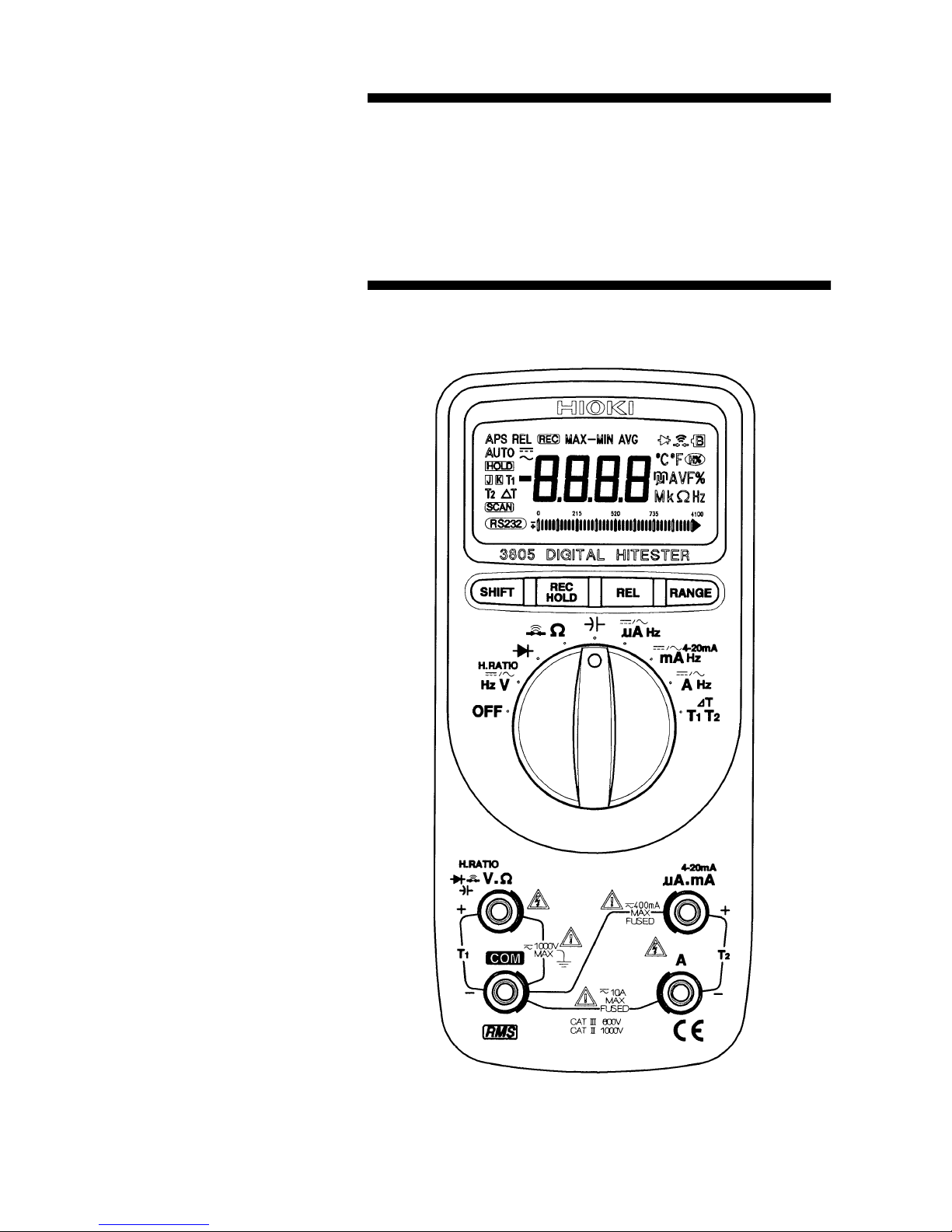
The multimeter is shown in the following Figure.
This meter has a lot of functions can be used in
HVAC, Power, Process fields, Electronic/Electrical
system diagnostics and troubleshooting. It will be
the best one of your need. See below detail:
Resolution of display: 9,999 counts for Voltage
and frequency and 3,999 counts for other
measurements.
TRUE RMS measurement for non-linear and
traditional loads.
Both paths of Current and Voltage can do
frequency measurement.
The thermocouple types of temperature
measurement can be selected K and J.
Scan T1, T2 and T1-T2 displays.
% of mA display can be selected for 4-20 mA or
0-20 mA.
The timer of auto power save can be adjusted
from 1 to 99 minutes even disable this function.
Dynamic Recording helps to record the variation
of tests.
Data Hold to freeze displayed digital value.
Refresh Hold to freeze the digital value for
difficult measuring place.
Relative function
Auto and Manual Ranging
Communication with RS-232C
Page 17
3
_______________________________________________
Chapter 2 Names and Functions of Parts
_______________________________________________
Chapter 2
Names and
Functions of Parts
Page 18
4
_______________________________________________
Chapter 2 Names and Functions of Parts
_______________________________________________
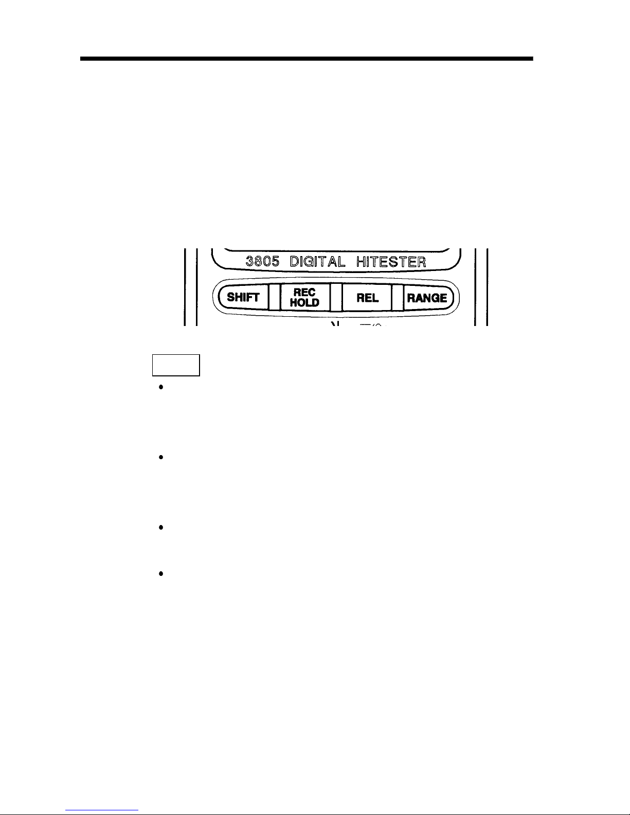
2.1 Push Buttons
The operation of push-button is shown as below.
When push the button, a display symbol will light,
and the beeper will sound. Turning the rotary switch
to another switch setting resets all push buttons to
their default state.
SHIFT
button
For voltage and current measurements, press this
button momentarily to cycle through DC,
frequency and AC tests.
For voltage measurement, press this button for
more than 1 second to set Harmonic ratio
measurement.
For mA measurement, press this button for more
than 1 second to set % of 4-20mA display.
For temperature test, press this button
momentarily to cycle through T2, ∆TandT1
tests. Press this button for more than 1 second to
set scanning the T1, T2 and ∆Tdisplays.
Page 19

5
_______________________________________________
Chapter 2 Names and Functions of Parts
_______________________________________________
For Ohm test, press button momentarily to toggle
"Audible continuity mode" ON/OFF. Pushing this
button for more than 1 second will exit the
continuity function and returns to the autoranging ohm measurement.
HOLD
button (Data Hold or Refresh Hold)
Press this button momentarily to toggle data hold
on or off. The display shows
HOLD
to indicate
the hold function.
The data hold function allows operator to hold the
displayed digital value, if you select " Refresh
Hold " by Power-ON Options, the reading is
updated to the display automatically when the
reading changes. The beeper sounds a tone to
remind user, that an update has occurred.
REC
button (Dynamic Recording)
Records maximum, minimum, and calculates true
average. Press this button for more than 1 second
to toggle recording mode on or off.
Press this button momentarily to cycle through
MAX, MIN, MAX-MIN, AVG and present (
REC
) readings.
The beeper sounds when a new maximum or
minimum value is recorded.
Page 20

6
_______________________________________________
Chapter 2 Names and Functions of Parts
_______________________________________________
REL
button
Press this button momentarily to toggle the relative
mode ON or OFF.
RANGE
button
In auto-range press this button momentarily to
select manual range and turn off the "AUTO"
annunciator.
In manual range, press this button momentarily to
step up 1 range at one time, press this button for
more than 1 second to select auto-range.
In auto-range, the "AUTO" annunciator is lit and
the meter will select an appropriate range for
measurement being made. If a reading is greater
than maximum available range, "OL"(overload) is
displayed on the screen. The meter selects a lower
range when reading is less than about 9% of full
scale.
For temperature measurement, press this button
momentarily to cycle throughK/ ,K/ ,J/
andJ/ , then come backK/ .Thesesetswill
disappear after power save. It will be set to
original setup condition when power ON.
Page 21
7
_______________________________________________
Chapter 2 Names and Functions of Parts
_______________________________________________
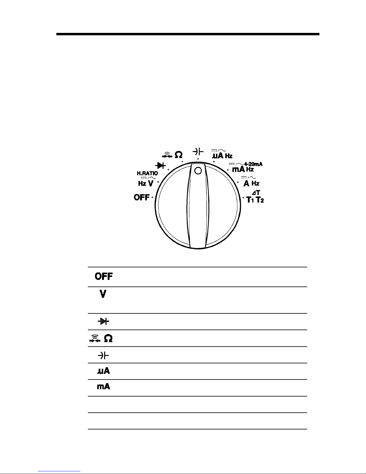
Power off position.
AC or DC voltage measurements.
Initial test is defined to AC.
Diode Check
Ohm and Continuity measurements
Capacitance measurement.
AC or DC Current measurements
AC or DC Current measurements.
A
AC or DC Current measurements.
T
1
T
2
Temperature measurement
2.2 Rotary Switch
To select function, turn the rotary switch to a switch
setting. Then the meter is ready for use. (If you
press and hold any push button while pushing the
meter from OFF to ON, the display will remain lit
until the push button is released.)
Page 22
8
_______________________________________________
Chapter 2 Names and Functions of Parts
_______________________________________________
2
3
4
1
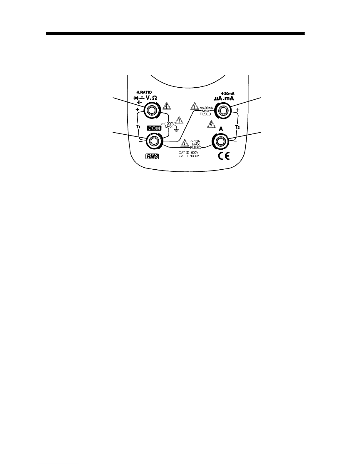
2.3 Input Terminal
1. Volts, Ohms, Diode, T1, Capacitance and
Frequency of Voltage measurements.
2. Common terminal for all measurements except
temperature of T1 test.
3. Current (maximum 400 mA) and temperature of
T2 measurements.
4. Current (maximum 10 A continuous) and
temperature of T2 measurements.
Page 23
9
_______________________________________________
Chapter 2 Names and Functions of Parts
_______________________________________________
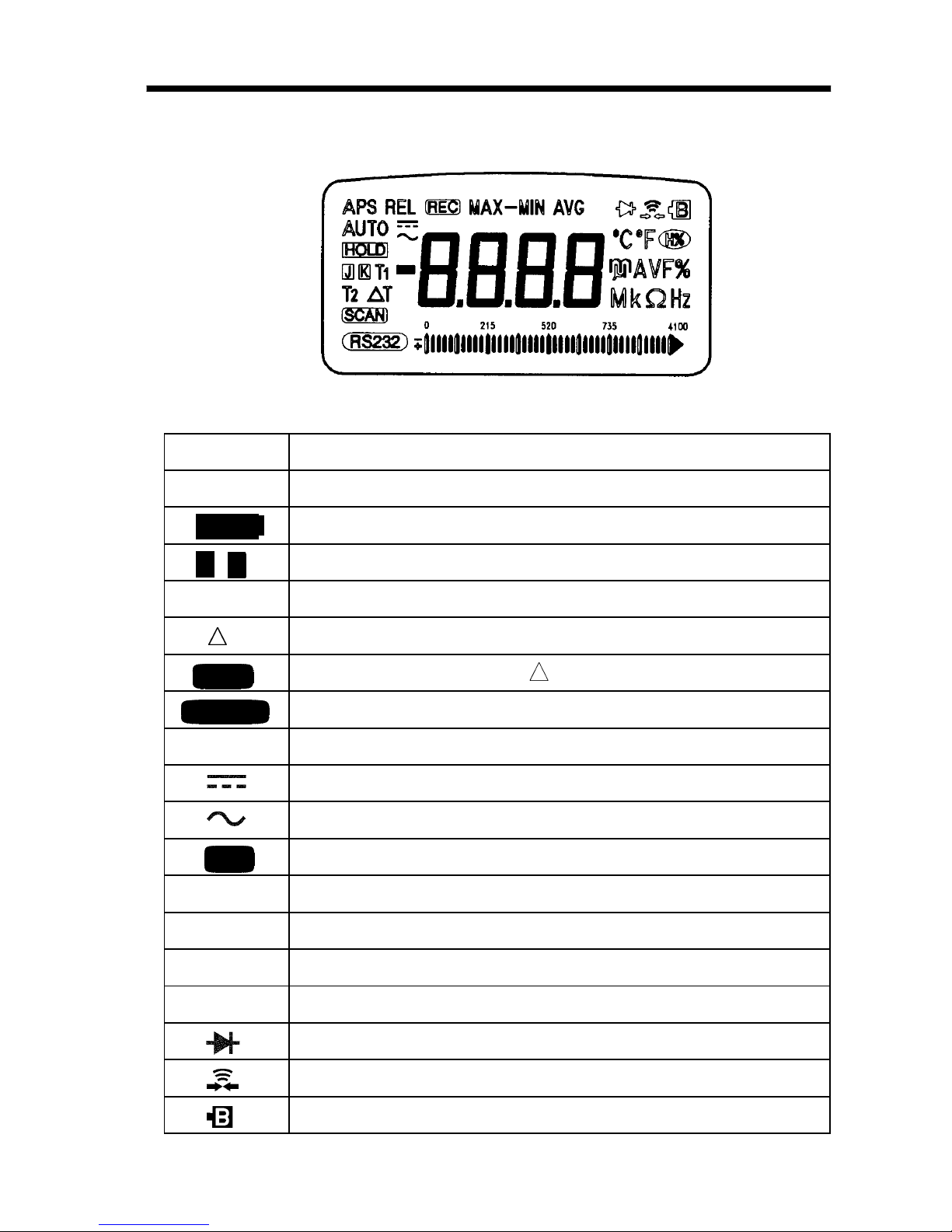
APS
Enable Auto power save
A
UTO
Indicates AUTO range Mode
HOLD
Data hold annunciator
J
K
Thermocouple type display
T1T
2
T1 or T2 temperature measurement
T
T1-T2 temperature measurement
SCAN
Scan the T1, T2 and T measurements
RS232C
Enable RS-232C
REL
Relative mode annunciator
Direct Current or Voltage
Alternating Current or Voltage
REC
Dynamic recording mode, Present reading
MAX-MIN
Different reading for MAX-MIN
MAX
Maximum reading
MIN
Minimum reading
AVG
Average reading
Diode measurement
Continuity function annunciator
Low battery indicator
2.4 LCD Display Illustration
Page 24
10
_______________________________________________
Chapter 2 Names and Functions of Parts
_______________________________________________
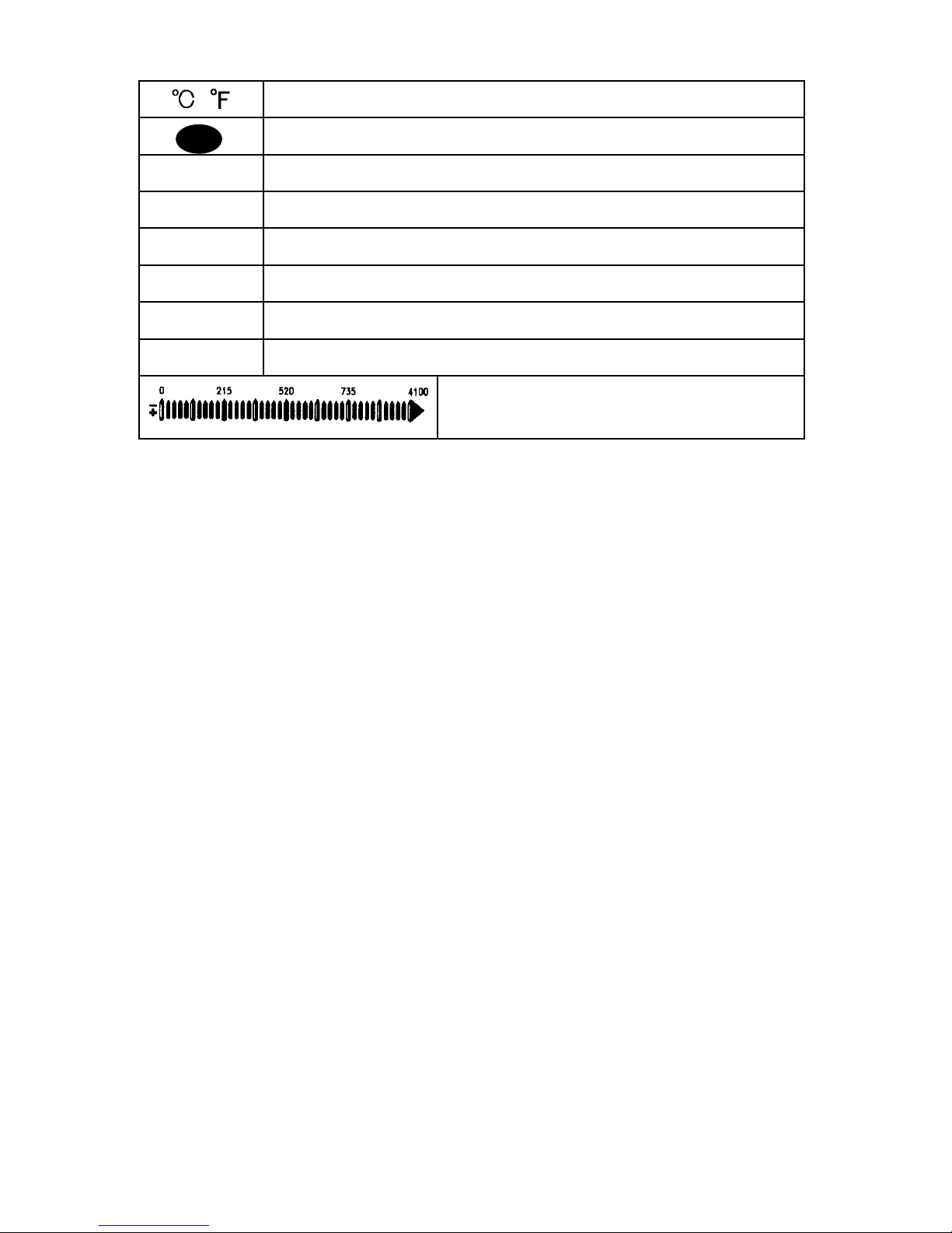
,
Units of Temperature
H%
Harmonics ratio
%
% display for 4-20mA measurement
mV
Units of Voltage measurement
µ
m
A
Units of Current measurement
µ
mF
Units of Capacitance measurement
Mk Ω
Units of Resistance (ohm) measurement
kHz
Units of frequency measurement
Bar-graph indicator
Page 25

11
_______________________________________________
Chapter 3 Measurement Procedures
_______________________________________________
DANGER
Observe the following precautions to avoid
electric shock.
Al ways verify the appropriate setting of the
function selector before connecting the test
leads.
Disconnect the test leads from the
measurement object before switching the
function selector.
NOTE
Chapter 3
Measurement
Procedures
When measuring voltage which includes harmonic
waves
(ex. horizontal output of TV), there is the possibility
that a setting error may occur.
Page 26

12
_______________________________________________
Chapter 3 Measurement Procedures
_______________________________________________
Preparation for Measurement
The safety caps are attached to the test leads.
Remove these caps before connecting to the unit.
Page 27

13
_______________________________________________
Chapter 3 Measurement Procedures
_______________________________________________
DANGER
The maximum input voltage is 1000 VDC, 1000
Vrms or 10
6
V Hz. Attempting to measure
voltage in excess of the maxi mum input could
destroy the product and result in personal
injury or death.
To avoid electrical shock, be careful to avoid
shorting live lines with the test leads.
For safety, test lead connections must always
be made at the secondary side of a circuit
breaker.
3.1 Voltage Measurement
Page 28

14
_______________________________________________
Chapter 3 Measurement Procedures
_______________________________________________
3.1.1 AC Voltage Measurement
(1) Set the rotary switch to "Hz
/ V ".
(2) Connect the black test lead to "COM" terminal
and red test lead to " " terminal.
(3) Touch the test leads to the test points and read
the display.
Page 29

15
_______________________________________________
Chapter 3 Measurement Procedures
_______________________________________________
NOTE
3.1.2 Frequency Measurement
(1) Set the rotary switch to "Hz
/ V ".
(2) Press
SHIFT
button momentarily two times to
set frequency measurement.
(3) Connect the black test lead to "COM" terminal
and red test lead to "
" terminal.
(4) Touch the test leads to the test points and read
the display.
The bar graph is used to indicate the value of AC
voltage.
Page 30

16
_______________________________________________
Chapter 3 Measurement Procedures
_______________________________________________
3.1.3 DC Voltage Measurement
(1) Set the rotary switch to "Hz
/ V ".
(2) Push
SHIFT
button momentarily to set DC test.
(3) Connect the black test lead to "COM" terminal
and red test lead to "
" terminal.
(4) Touch the test leads to the test points and read
the display.
Page 31

17
_______________________________________________
Chapter 3 Measurement Procedures
_______________________________________________
DANGER
Never apply voltage to the test leads when the
Diode Check functions is selected. Doing so
may damage the product and result in personal
injury.
To avoid electrical accidents, remove power
from the circuit before measuring.
3.2 Diode Check
A good diode allows current to flow in one direction
only. To test a diode, turn the power off, remove the
diode from the circuit, and proceed as follows:
(1) Set the rotary switch to "
" position.
(2) Connect the black test lead to "COM" terminal
and red test lead to "
" terminal.
(3) Touch the test leads to diode and read the
display.
(4) Touch the red lead to the positive side of the
diode and the black lead to the negative side.
The meter can display diode voltage drops to
approximately 2.5 V. A typical voltage drop is
0.3 to 0.8 V, and the meter will sound a beep to
remind user.
Page 32

18
_______________________________________________
Chapter 3 Measurement Procedures
_______________________________________________
Reverse the test leads and measure the voltage
across the diode again. If the diode is:
Good : "OL" is displayed.
Shorted : Near 0 V drop is displayed in both
directions, and the beeper sounds
continuously.
Open : "OL" is displayed in both directions.
Repeat step (3) and (4) for other diodes.
Page 33

19
_______________________________________________
Chapter 3 Measurement Procedures
_______________________________________________
DANGER
Never apply voltage to the test leads when the
Resistance, Continuity Check functions are
selected. Doing so may damage the product
and result in personal injury.
To avoid electrical accidents, remove power
from the circuit before measuring.
3.3 Resistance Measurement
(1) Set the rotary switch to " ".
(2) Connect the black test lead to "COM" terminal
and red test lead to "
" terminal.
(3) Touch the test leads to resistor and read the
display.
(4) Press
SHIFT
button momentarily to toggle
CONTINUITY function ON/OFF. The continuity
range is 0 to 400.0 Ω.
(5) Momentarily pushing this button will only turn
the beeper off. While testing continuity, the
beeper will sound if the resistance falls below
100 counts.
Page 34

20
_______________________________________________
Chapter 3 Measurement Procedures
_______________________________________________
Page 35

21
_______________________________________________
Chapter 3 Measurement Procedures
_______________________________________________
DANGER
Never apply voltage to the test leads when a
current measurement function is selected.
Doing so may damage the product and result in
personal injury.
To avoid electrical accidents, remove power
from the circuit before connecting the test
leads.
WARNING
To prevent electrical accidents, do not use the
tester to measure current when the electric
potential is 600 V or greater. The current
function overload protection trips at either 600
V DC, 600 V rms.
3.4 Current Measurement
Page 36

22
_______________________________________________
Chapter 3 Measurement Procedures
_______________________________________________
NOTE
Instrument operated by
alternating current
3.4.1 AC Current Measurement
(1) Set the rotary switch to "Hz
/ A ".
(2) Connect the black test lead to "COM" terminal
and red test lead to "A" terminal.
(3) Touch the test leads to the test points and read
the display.
If the reading is lower than 400 mA, to get better
resolution of display, please turn the rotary switch to
mA or µA position and remove the red test lead to
"µAmA" terminal.
Page 37

23
_______________________________________________
Chapter 3 Measurement Procedures
_______________________________________________
NOTE
Instrument operated by
alternating current
3.4.2 Frequency Measurement
(1) Set the rotary switch to "Hz
/ A ".
(2) Press
SHIFT
button momentarily two times to
set frequency measurement.
(3) Connect the black test lead to "COM" terminal
and red test lead to "A" terminal.
(4) Touch the test leads to the test points and read
the display.
The bar graph is used to indicate the value of AC
current.
Page 38

24
_______________________________________________
Chapter 3 Measurement Procedures
_______________________________________________
NOTE
3.4.3 DC Current Measurement
(1) Set the rotary switch to "Hz
/ A ".
(2) Push
SHIFT
button momentarily to set DC test.
(3) Connect the black test lead to "COM" terminal
and red test lead to "A" terminal.
(4) Touch the test leads to the test points and read
the display.
If the reading is lower than 400 mA, to get better
resolution of display, please turn the rotary switch to
mA or µA position and remove the red test lead to
"µAmA" terminal.
Page 39

25
_______________________________________________
Chapter 3 Measurement Procedures
_______________________________________________
DANGER
Never apply voltage to the test leads when the
Capacitance functions are selected. Doing so
may damage the product and result in personal
injury.
To avoid electrical accidents, remove power
from the circuit before measuring.
3.5 Capacitance Measurement
(1) Set the rotary switch to " " position
(2) Connect the red lead to "
" terminal, and black
lead in "COM" terminal.
(3) Open test leads, then push
REL
button
momentarily to zero the residual.
(4) Remove the capacitor from circuit board or
device.
(5) Connect the test lead across the capacitor and
read the display.
Page 40

26
_______________________________________________
Chapter 3 Measurement Procedures
_______________________________________________
NOTE
Observe polarity when measuring the polarized
capacitors.
Discharge capacitor before measurement.
When testing low-capacitance devices, noise
introduced into the test leads from the human
body may prevent the measured value from
stabilizing. If this occurs, use the optional 9617
CLIP ON BASE or the optional 9618 CLIP-TYPE
LEAD and keep hands away from the leads
during measurement.
Page 41

27
_______________________________________________
Chapter 3 Measurement Procedures
_______________________________________________
DANGER
Do not apply a voltage while a temperature
range is selected. Applying a voltage may result
in damage to the unit, or a serious accident.
Do not input a voltage exceeding 30 Vrms or 60
VDC to the temperature probe.
3.6 Temperature Measurement
(1) Turn the rotary switch to the "T1 T2" position.
(2) Press
SHIFT
button momentarily to cycle
through T2, T1 and
T tests. Press this button
for more than 1 second to set scanning the T1,
T2 and
Tdisplays.
(3) Press
RANGE
button momentarily to cycle
through K/
,K/ ,J/ and J/ , then come
back K/
. These sets will disappear after power
off. It will be set to original setup condition
when power ON.
(4) Plug the thermocouple probe into T1 or T2 for
the plus side and the minus side terminal.
(5) Attach the thermocouple to the heated source.
(6) Read the display.
Page 42

28
_______________________________________________
Chapter 3 Measurement Procedures
_______________________________________________
NOTE
Do not sharply bend the thermocouple leads.
Repeatedly bending the leads can break them.
The optional temperature probes are all the K type
probe. Please use it in accordance with the
instruction manual of the temperature probe. For J
type temperature probes , please read its manual
prior to use.
The temperature range of the 3805 is different
from the range of temperature probes. Please
measure within the common temperature range.
Page 43

29
_______________________________________________
Chapter 3 Measurement Procedures
_______________________________________________
T
1
-
T
2
T2
T
1
SCAN MODE
This function will assist you to see the T1, T2 and
T (T1-T2) display, quickly. Press and hold
SHIFT
button for more than 1 second to toggle SCAN
mode ON or OFF. When SCAN mode is selected,
the display continuously cycles between T1, T2 and
T temperature readings, and the annunciator of
will be lit. The cycling time is around 3 to 4
seconds, and the T1, T2 and
T will be lit to
indicate which reading has been display,
respectively. For bar graph, it is using to indicate
the environment temperature. For scale
, each bar
is equal 1
.Forscale , each bar is equal 2.5 .
Page 44

30
_______________________________________________
Chapter 3 Measurement Procedures
_______________________________________________
Page 45

31
_______________________________________________
Chapter 4 Special Functions Instructions
_______________________________________________
Chapter 4
Special Functions
Instructions
This multi-meter provides the operator with various
functions including:
(1) Data Hold
(2) Refresh Hold
(3) Dynamic Recording
(4) Harmonic Ratio Measurement
(5) Relative (Zero)
(6) % of mA Measurement (4-20 mA)
(7) Beeper On/Off
(8) Set Up
(9) Communication (RS-232C)
Page 46

32
_______________________________________________
Chapter 4 Special Functions Instructions
_______________________________________________
NOTE
4.1 Data Hold
The data hold function allows operators to hold the
displayed digital value, while the analog bar graph
continues showing the present readings. Press
HOLD
button to enter the data hold mode, and the "
HOLD
"
will be displayed. Press the button again to exit. The
present reading is now shown.
The range is held in the case of auto range.
Page 47

33
_______________________________________________
Chapter 4 Special Functions Instructions
_______________________________________________
NOTE
4.2 Refresh Hold
The reading is updated the value automatically and
the beeper sounds when the measurement value
changes 30 counts at least.
The refresh hold mode is effective until the power
supply is turned off.
(1) To active the refresh hold mode, turn on the
power supply while pressing the
HOLD
button.
(2) Release the button after all the LCD segments
are lit. Press any button for the measurement
modes
(3) Press
HOLD
button to select ON/OFF of the
refresh hold. While the refresh hold mode is
effective ,
HOLD
is displayed.
When the reading value is unstable, the 3805 may
not update the display.
In the voltage, current, and capacitance function,
the reading is not updated when the measurement
value is less than 50 counts.
In the resistance and diode function, the reading
is not updated when the reading is "OL" or the
test leads are open.
The hold mode and the refresh hold mode use the
same display, so please pay attention when
measuring to make sure you are in the correct
mode.
Page 48

34
_______________________________________________
Chapter 4 Special Functions Instructions
_______________________________________________
4.3 Dynamic Recording
The dynamic recording mode can be used to catch
intermittent and turn on or turn off surges, verify
performance, measure while you are away, or take
readings while you are operating the equipment
under test and can not watch the meter.
The average reading is useful for smoothing out
unstable or changing inputs, estimating the percent
of time a circuit is operational, or verifying circuit
performance.
The operational procedures are described below:
(1) Press
REC
button for more than 1 second to
enter the dynamic recording. The present value
is stored to memories of maximum, minimum
and average, and the annunciator turns on.
(2) Press
REC
button for more than 1 second to
toggle recording mode on or off.
(3) Press
REC
button momentarily to cycle through
maximum, minimum, maximum - minimum,
average and present readings. The MAX, MIN,
MAX-MIN, AVG or annunciator will turn on
respectively to indicate what value is being
displayed.
Page 49

35
_______________________________________________
Chapter 4 Special Functions Instructions
_______________________________________________
NOTE
(4) The beeper sounds when a new maximum or
minimum value is recorded.
(5) If an overload is recorded the averaging function
is stopped. An average value becomes
"OL"(overload).
In dynamic recording, the auto power save feature
is disabled, after disabled and the "APS" turns
off.
Select dynamic recording in auto range, it will
record the values of MAX, MIN or AVG for
different ranges.
The record speed of dynamic recording is about
100 ms (0.1 s).
The average value is the true average of all
measured values taken since the recording mode
was entered.
If the range is changed in the manual range mode
or the function is changed, the dynamic recording
function is canceled.
Page 50

36
_______________________________________________
Chapter 4 Special Functions Instructions
_______________________________________________
Press REC button for
more than 1 second
Current value
Maximum value
Minimum value
Max. - Min. value
Average value
Page 51

37
_______________________________________________
Chapter 4 Special Functions Instructions
_______________________________________________
NOTE
4.4 Harmonic Ratio Measurement
The harmonic ratio measurement function shows
how much the wave is distorted.
The distortion rate of the wave is shown in
accordance with the following formula.
The harmonic ratio = (the conversion value from the
mean value - the true RMS value) X
100/the true RMS value.
In order to convert from the mean value to the RMS
value, the mean value is multiplied by 1.11.
Although the harmonic ratio becomes 0% when a
sine wave is measured, the harmonic ratio becomes
11.1% in the case of a square wave.
(1) Set the rotary switch to "Hz
/ V ".
(2) Push and hold
SHIFT
button for more than 1
second to enter Harmonic Ratio mode.
(3) Connect the black test lead to "COM" terminal
and red test lead to "
" terminal.
(4) Touch the test leads to the test points and read
the display.
The bar graph is used to indicate the value of AC
voltage, however if you push
RANGE
button
momentarily, the digits will indicate the value of
AC voltage. The meter will return to indicate the
value of Harmonic Ratio after 3 seconds
automatically.
Page 52

38
_______________________________________________
Chapter 4 Special Functions Instructions
_______________________________________________
NOTE
4.5 Relative (Zero)
The relative function subtracts a stored value from
the present measurement and displays the result.
(1) Press
REL
button momentarily to set the relative
mode.Itwillsetthedisplaytozeroandstores
the displayed reading as a reference value, also
"REL" is displayed.
(2) Press this button again to exit the relative mode.
Both auto-range or manual range can set relative
mode.
The relative mode can't be set when an overload
has occurred.
Page 53

39
_______________________________________________
Chapter 4 Special Functions Instructions
_______________________________________________
NOTE
4.6 % of mA Measurement (4-20mA)
The 4-20 mA (0-20 mA) function converts 4 mA (0
mA) as 0% and 20 mA as 100%.
It is used in instrumentation.
(1) Set the rotary switch to "Hz
/ mA ".
(2) Push and hold
SHIFT
button for more than 1 sec
to set % of mA test.
(3) Connect the black test lead to "COM" terminal
and red test lead to "µAmA" terminal.
(4) Touch the test leads to the test points and read
the display.
The 0-20mA mode and the 4-20mA mode use the
same display, so please confirm the correct display
at the set up mode.(Refer to Section 4.8.2 )
Page 54

40
_______________________________________________
Chapter 4 Special Functions Instructions
_______________________________________________
4.7 Beeper On/Off
Press and hold
REL
button while turning the rotary
switch to any on position. Turns off all beeper
functions. Beeper off function remains selected until
the meter is turned off.
Page 55

41
_______________________________________________
Chapter 4 Special Functions Instructions
_______________________________________________
SHIFT
Press button momentarily to select
other setup modes. The existing value
will be indicated on the display.
HOLD
Push this button momentarily to adjust
value.
REL
Press this button momentarily to save
the settling value into the memory.
RANGE
Press this button momentarily to exit
setup mode, it will come to the normal
measurement.
4.8 Set Up
This multi-meter provides the operator with set up
procedures below:
(1) Timer setting for auto-power save
(2) Selecting % display for 4-20 mA, or 0-20 mA
(3) Selecting J/k types and
/ display
How to entry setup mode
Press and hold
SHIFT
button then turns the rotary
switch to any ON positions. Release pressing button
after the LCD lit all signs. It will enter setup mode,
first mode is time setting for auto power save. In the
setup mode, the button will be operated, see
following explanation:
Page 56

42
_______________________________________________
Chapter 4 Special Functions Instructions
_______________________________________________
NOTE
4.8.1 Timer Setting for Auto-power Save
Between the auto power save setting screen and the
screen for selecting 4-20mA or 0-20mA
measurement, the setting screen for the back light
appears. Although this screen appears, the 3805 can
not perform this function. Because the 3805 does
not include a back light, please ignore this display.
When the meter is to be used for long periods of
time, the operator might want to disable the auto
power save. Once the auto power save function is
disabled, the meter will stay on continuously. The
meter will shut off by turning the rotary switch to
the off position.
In general, the auto power save function will turn
the meter off if neither rotary switch nor push
button is activated for existing setting. The LCD
will indicate existing time setting, and the APS will
light. You can set the timer from 0 to 99 minutes.
Each step is 1 minute by pushing
HOLD
button.
When you set the timer to zero, the auto power save
will be disabled, the meter will stay on
continuously. Press
REL
button momentarily to save
your setting after you finished. Press
RANGE
button
momentarily to exit set up procedures.
Page 57

43
_______________________________________________
Chapter 4 Special Functions Instructions
_______________________________________________
NOTE
4.8.2 Selecting % Display for 4 to 20 mA
The instrument will auto-power save, if none of the
following happens. You can push any buttons to
wake-up the meter after auto power save.
Push buttons used.
Measurement function changed.
Set dynamic recording.
Disable auto power save with power-on option.
In this mode, you can set % display for other
ranges. The LCD will indicate existing setting, and
the % and mA will light. The digit will indicate
existing setting. For example of 4 to 20 mA, the
digits will show "0420". You can press the
HOLD
button to toggle 04 to 20mA and 00 to 20mA.
Press
REL
button momentarily to save your setting
after you finished. Press
RANGE
button
momentarily to exit set up procedures.
Page 58

44
_______________________________________________
Chapter 4 Special Functions Instructions
_______________________________________________
NOTE
4.8.3 Selecting J/ k Types and / Display
The display will indicate existing setting. Press
HOLD
button momentarily to change the setting. It
will cycle through K/
,K/ ,J/ and J/ , then
come back K/
.Press
REL
button momentarily to
save your setting after you finished. Press
RANGE
button momentarily to exit set up procedures.
The following expression converts degrees
Fahrenheit into degree Celsius
=1.8 +32
Page 59

45
_______________________________________________
Chapter 4 Special Functions Instructions
_______________________________________________
NOTE
4.9 Communication (RS-232C)
This meter has a communication capability. This
function will assist user to recording and keeping
data easy.
We offer the 3854 RS-232C PACKAGE to optional
accessories. This package includes a cable with
optical receiver, positional connector and a software
disc.
Please refer following procedures if you want to
communicate with personal computer.
(1) Fixed the connector to the holster.
(2) Fixes one side of cable to the positional
connector, and connect the 9 pin's terminal of
cable to communication port 1 or 2 of personal
computer.
(3) Push and hold the
RANGE
button then turn the
rotary switch from off position to any function,
wait 1 second, then release the push button. You
will find that the annunciator of
RS232
is light
on the display.
(4) Execute the software to take the data for your
necessary
Please refer to manual that the use method of
software belonged to 3854 RS-232C PACKAGE .
The RS-232C function remains selected until the
meter is turned off.
Page 60

46
_______________________________________________
Chapter 4 Special Functions Instructions
_______________________________________________
Please fix the connector so that
the label becomes downward.
Page 61

47
_______________________________________________
Chapter 5 Specifications
_______________________________________________
Measurement
Mode
Dual integration
AC measurement
Mode
True RMS measurement
Function
DCV, ACV, DCA, ACA, OHM, Diode
check, Audible continuity, Capacitor,
Temperature, % of 4-20 mA and
Frequency tests.
Harmonics ratio measurement.
The thermocouple types can be selected
for K and J.
Additional
Function
Auto Range function
Dynamic Recording function
Data Hold
Refresh Hold
Harmonic Ratio Measurement
% of mA Measurement (4-20mA)
Relative function
Auto Power Save function
Low Battery Indicate function
RS-232C Interface
Type of Display
LCD
Chapter 5
Specifications
5.1 General Specifications
Page 62

48
_______________________________________________
Chapter 5 Specifications
_______________________________________________
Display
The liquid crystal display (LCD) is 4 digits with
maximum reading 3,999/9,999 counts.
41 segments analog bar graph and full
annunciator
Automatic polarity indication.
Range
Selection
Automatic or Manual
Measuring Rate
3 times per second.
1 time per second for frequency
measurement.
Constituent
Inputs
V, Hz,Ω, C, Audible continuity, Diode,
H.RATIO, T1 Terminal
µ
A, mA, 4-20mA, T2 Terminal
A Terminal
COM Terminal
4 Terminal components
Power Supply
6F22 manganese battery X1 (9V)
Low Battery
Indicator
The " " appears when the battery
voltage drops below 6.3 to 7.5V
(approx.).
Dimension
Approx. 76W X 167H X 33D mm
Approx. 2.99"W X 6.54"H X 1.30"D
Mass
Approx. 300 g (with a battery included)
Approx. 10.6 oz.
Approx. 400 g (with protective holster and
a battery)
Approx. 14.1 oz.
Dielectric Strength
6 kVrms sin (1 minute at 50/60 Hz)
Electrical
Specifications
Accuracy: See "5.2 Accuracy Chart"
Accuracy Guarantee: 23
5 (73 5
), less than 80% RH (no condensation)
Supply Voltage: 9 V to Low Battery
Indicator appears
Page 63

49
_______________________________________________
Chapter 5 Specifications
_______________________________________________
Temperature
Coefficient
specified accuracy X 0.15/
(from 0 to 18 or 28 to 40 )
(from 32 to 64
or 82 to 104 )
Noise
Rejection
NMRR DCV: more than -60 dB (50/60 Hz)
CMRR DCV: more than -120 dB (50/60 Hz)
ACV: more than -60 dB (50/60 Hz)
(1 kΩUnbalance)
Rated Supply
Voltage
9.0VDC X 1 (6F22 manganese battery)
Rated Power
35 mVA (Typ.)
(DCV Supply Voltage=9.0 V )
50 mVA (Max.)
(Diode (RS232-C) Supply Voltage=9.0 V)
Continuous
Operating
Time
Approx. 100 hours (DCV Function at 6F22
manganese battery)
Operating
Temperature
0to40 (32 to 104 ) less than 80% RH
(no condensation)
Storage
Temperature
-20 to 60 (-4 to 140 ) less than 80% RH
(no condensation)
Location for
Use
Indoors, altitude up to 2000 m
Accessories
3851-10 TEST LEAD (a pair)
Protective holster
Manual
6F22 manganese battery (built in)
Page 64

50
_______________________________________________
Chapter 5 Specifications
_______________________________________________
Option
3851-10 TEST LEAD (a pair)
Protective holster
3853 CARRYING CASE
3854 RS-232C PACKAGE
9180, 9182, 9183, 9472 to 9475
SHEATH TYPE TEMPERATURE PROBE
9181 SURFACE TEMPERATURE PROBE
9476 SURFACE TYPE TEMPERATURE
PROBE
9617 CLIP ON BASE
9618 CLIP-TYPE LEAD
Protective
Fuse
µA µA
D086483P (Made by FERRAZ Inc.)
0.5 A/660 V,φ6.35-32 mm, Breaking Capacity
30 kA
or 70125(Made by SIBA Inc.)
0.5 A/700 V,φ6.35-32 mm, Breaking Capacity
50 kA
A
TDC600 ( Made by Cooper Bussmann Inc. )
10 A/600 V,φ6.35-25.35 mm, Breaking
Capacity 10 kA
Applicable
Standards
Safety
EMC
EN 61010-1:2001
EN 61010-2-031:1994
Pollution 2, Measurement Category II
(1000 V), Measurement Category III
(600 V)
(anticipated transient overvoltage
6000 V)
UL 3111-1:1994
CAN/CSA-C22.2 No.1010-1-92+B-97
CAN/CSA-C22.2 No.1010.2.031-94
EN61326:1997+A1:1998+A2:2001
+A3:2003
Page 65

51
_______________________________________________
Chapter 5 Specifications
_______________________________________________
Range Resolution Accuracy
Overload
Protection
999.9 mV 0.1 mV 0.2%rdg. 5dgt.
1000 V DC/
1000 V rms
or 10
6
V Hz
9.999 V 1mV
0.1%rdg. 2dgt.
99.99 V 10 mV
999.9 V 0.1 V 0.4%rdg. 5dgt.
Range Resolution Accuracy
Overload
Protection
999.9 mV 0.1 mV 2.5%rdg. 5dgt.
1000 V DC/
1000 V rms
or 10
6
V Hz
9.999 V 1mV 1.1%rdg. 6dgt.
99.99 V 10 mV
1.1%rdg. 5dgt.
999.9 V 0.1 V
Range Resolution Accuracy
Overload
Protection
999.9 mV 0.1 mV -
1000 VDC/
1000 Vrms
or 10
6
V Hz
9.999 V 1mV 1.1%rdg. 6dgt.
99.99 V 10 mV
1.1%rdg. 5dgt.
999.9 V 0.1 V
5.2 Accuracy Chart
Temperature and humidity for guaranteed accuracy
23 5 (73 9 ), 80% RH or less, no condensation
Guaranteed accuracy period
1 year
(1) DC VOLTAGE
Input Impedance: 10 MΩ (15 MΩ nominal for 999.9 mV range)
(2) AC VOLTAGE
1. 40 Hz to 200 Hz
2. 200 Hz to 500 Hz
Page 66

52
_______________________________________________
Chapter 5 Specifications
_______________________________________________
Range Resolution Accuracy
Overload
Protection
999.9 mV 0.1 mV 1000 V DC/
1000 V rms
or 10
6
V Hz
9.999 V 1mV 2.0%rdg. 6dgt.
99.99 V 10 mV 2.0%rdg. 6dgt.
999.9 V 0.1 V -
Range
Resolu-
tion
Accuracy
Internal
Resistance
(approx)
Overload
Protection
400.0 µA 0.1 µA 0.2%rdg. 3dgt. 100 Ω
0.5 A/600 V
Quick
Acting Fuse
4000 µA 1 µA 0.1%rdg. 3dgt. 100 Ω
40.00 mA 10 µA 0.2%rdg. 3dgt. 1 Ω
400.0 mA 0.1 mA 0.1%rdg. 3dgt. 1 Ω
4.000 A 1mA 0.3%rdg. 3dgt. 0.01 Ω 10 A/600 V
Quick
Acting Fuse
10.00 A 10 mA 0.3%rdg. 3dgt. 0.01 Ω
3. 500 Hz to 2 kHz
Measurement accuracy is prescribed from 5% to 100% of the range
For lower than 5.0mV,the specification will add 45dgt to specified
accuracy.
Input Impedance: 10 MΩ (999.9 mV range 15 MΩ)
Crest factor: 3
(3) DC CURRENT
10 A continuous, 10 to 20 A for 30 seconds maximum with 5
minutes cool down interval.
Page 67

53
_______________________________________________
Chapter 5 Specifications
_______________________________________________
Range
Resolut
-ion
Accuracy
Internal
Resistance
(approx)
Overload
Protection
400.0 µA 0.1 µA
1.0%rdg. 5dgt.
(40 Hz to 500 Hz)
1.5%rdg. 5dgt.
(500 Hz to 2 kHz)
100 Ω
0.5 A/600 V
Quick
Acting Fuse
4000 µA 1 µA 100 Ω
40.00 mA 10 µA 1 Ω
400.0 mA 0.1 mA 1 Ω
4.000 A 1mA 0.01 Ω 10 A/600 V
Quick
Acting Fuse
10.00 A 10 mA 0.01 Ω
Range Voltage
0.0% to 99.9% 100 mV AC to 1000 V AC
(4) AC CURRENT
Measurement accuracy is prescribed from 5% to 100% of the range
10 A continuous, 10 to 20 A for 15 seconds maximum with 5
minutes cool down interval.
Crest factor: 3
(5) HARMONIC RATIO
Harmonics Ratio function generates a value between 0% to 100% to
indicate the deviation of non-sinusoidal to a sinusoidal waveform,
which is a good indication of the presence of harmonics. Pure
sinusoidal waveforms without harmonics have a Harmonics Ratio of
0%. The higher Harmonics Ratio, the more harmonics are present.
Page 68

54
_______________________________________________
Chapter 5 Specifications
_______________________________________________
Range
Resolut
-ion
Accuracy
Maximum
Test
Voltage
Overload
Protection
400.0 Ω 0.1 Ω
0.5%rdg. 3dgt.
3.3 V
max.
600 V DC/
600 V rms
4.000 kΩ 1 Ω
40.00 kΩ 10 Ω
1.28 V
max.
400.0 kΩ 100 Ω
4.000 MΩ 1kΩ 0.8%rdg. 3dgt.
40.00 MΩ 10 kΩ 1.2%rdg. 3dgt.
Range Threshold level
Overload
Protection
CONTINUITY
The beeper will sound if the resistance
falls below 100 counts.
600 V DC/
600 V rms
Range Resolution Accuracy
Overload
Protection
4.000 µF 1nF
2.0%rdg. 4dgt.
600 V DC/
600 V rms
40.00 µF 0.01 µF
400.0 µF 0.1 µF 3.5%rdg. 4dgt.
9999 µF 1 µF
3.5%rdg. 5dgt.
>2mF, NO Spec
(6) RESISTANCE
(7) AUDIBLE CONTINUITY TEST
Relative mode is used in Audible continuity test function. Using
Relative mode to zero residual.
The measurement accuracy and open terminal voltage (test voltage)
are the same as these of Ω function.
(8) CAPACITANCE
The accuracy is based on the film capacitor or better. Using Relative
mode to zero residual.
Page 69

55
_______________________________________________
Chapter 5 Specifications
_______________________________________________
Range
Resolution
Accuracy
Test Current
Voltage
Overload
Protection
Diode
1mV
1.0%rdg. 2dgt.
approx. 0.7 mA
Less than 3.3 V
600 V DC/
600 V rms
Range Resolution Accuracy
Min. Input
Freq.
Overload
protection
9.999 Hz 0.001 Hz
0.05%rdg.
4dgt.
1Hz
1000 V DC/
1000 V rms
or
10
6
V Hz
99.99 Hz 0.01 Hz
999.9 Hz 0.1 Hz
9.999 kHz 1Hz
50.00 kHz 10 Hz
INPUT
RANGE
MINIMUM SENSITIVITY (rms sinwave)
40 Hz - 5 kHz 20 Hz
*
-15kHz
15 kHz - 50 kHz
999.9 mV 0.4 V 0.7 V -
9.999 V 0.8 V 0.8 V 3V
99.99 V 8V 8V 30 V
999.9 V 80 V 100 V 20 Hz
*
-10kHz
400.0 µA 50 µA
4000 µA 300 µA
40.00 mA 5mA
400.0 mA 30 mA
4.000 A 0.5 A
10.00 A 3A
(9) DIODE CHECK
In Audible continuity function if measurement voltage is about less
than 100 mV, the beeper sounds.
(10) FREQUENCY MEASUREMENT FOR VOLTAGE
FREQUENCY SENSITIVITY
Maximum input for specified accuracy = 10 x Range or 1000 V
*:
In the case of a square wave : from 10 Hz to 20 kHz.
Page 70

56
_______________________________________________
Chapter 5 Specifications
_______________________________________________
Range Resolution Accuracy
Overload
protection
-40 to 850 (K)
1 0.3%rdg. 3
600 V DC
/600 V rms
-40 to 650 (J)
-40 to 1562 (K)
1 0.3%rdg. 6
-40 to 1202 (J)
(11) K -TYPE TEMPERATURE TEST
Do not allow the temperature sensor to contact a surface that is
energized above 30 V RMS or 60 V DC, such voltages pose a
shock hazard.
The accuracy does not include the tolerance of thermocouple probe.
Page 71

57
_______________________________________________
Chapter 6 Maintenance and Service
_______________________________________________
WARNING
To avoid electric shock when replacing the
battery and fuse, first disconnect the test leads
from the object to be measured, then open the
cover.
After replacing the battery or fuse, replace the
cover and screws before using the product.
When replacing the battery, Be sure to insert
them with the correct polarity. Otherwise, poor
performance or damage from battery leakage
could result. Replace batter y only with the
specified type.
To avoid the possibility of explosion, do not short
circuit, disassemble or incinerate battery.
Handle and dispose of battery in accordance with
local regulations.
Replace the fuse only with one of the specified
characteristics and voltage and current ratings.
Using a non-specified fuse or shorting the fuse
holder may cause a life-threatening hazard.
Chapter 6
Maintenance and
Service
6.1 Changing the Battery and Fuses
Page 72

58
_______________________________________________
Chapter 6 Maintenance and Service
_______________________________________________
Use the following procedures to replace the battery,
or fuse.
(1) Using the rotary switch to turn the meter off,
and remove the test leads from terminals.
(2) Loosen 3 screws on bottom cover, pull up and
move the cover.
(3) Replace the defective battery.
The meter is powered by a 6F22 battery. Replace
battery if the low battery sign (
) is displayed
and flashes.
(4) Remove the defective fuse by gently prying one
end of the fuse loose and sliding the fuse out of
the fuse bracket.
Install a new fuse of the same size and rating.
Make sure the new fuse is centered in the fuse
holder. There are 2 types of fuses, one for the
µA , mA terminal and one for the A terminal.
Be sure to set the correct fuse.
(5) Reverse the procedure of opening cover to close
the bottom cover.
Page 73

59
_______________________________________________
Chapter 6 Maintenance and Service
_______________________________________________
For A terminal fuse :
TDC600 (Made by Cooper
Bussmann Inc.)
10A/600V, 6.35 mm-25.35
mm dia.
6F22 manganese batter
y
For µA mA terminal fuse :
D086483P
(Made by FERRAZ Inc.)
F0.5A/660V, 6.35mm32mm dia.
or 70125
(Made bySIBA Inc.)
0.5 A/700 V, 6.35-32 mm
dia.
Page 74

60
_______________________________________________
Chapter 6 Maintenance and Service
_______________________________________________
6.2 Cleaning
6.3 Service
To clean the product, wipe it gently with a soft
cloth moistened with water or mild detergent. Never
use solvents such as benzene, alcohol, acetone,
ether, ketones, thinners or gasoline, as they can
deform and discolor the case.
If the product seems to be malfunctioning, confirm
that the battery are not discharged, and that the test
leads, and fuse are not open circuited before
contacting your dealer or Hioki representative.
When sending the product for repair, pack the
product carefully so that it will not be damaged
during shipment, and include a detailed written
description of the problem. Hioki cannot be
responsible for damage that occurs during shipment.
Page 75

Page 76

Page 77

HIOKI 3805 DIGITAL HiTESTER
Instruction Manual
Publication date: September 2006 Revised edition 8
Edited and published by HIOKI E.E. CORPORATION
Technical Sales Support Section
All inquiries to International Sales and Marketing
Department
81 Koizumi, Ueda, Nagano, 386-1192, Japan
TEL: +81-268-28-0562 / FAX: +81-268-28-0568
E-mail: os-com@hioki.co.jp
URL http://www.hioki.co.jp/
Printed in Japan 3805A980-08
All reasonable care has been taken in the production
of this manual, but if you find any points which are
unclear or in error, please contact your supplier or
the International Sales and Marketing Department
at HIOKI headquarters.
In the interests of product development, the contents
of this manual are subject to revision without prior
notice.
Unauthorized reproduction or copying of this manual
is prohibited.
Page 78

Printed on recycled paper
HEAD OFFICE
81 Koizumi, Ueda, Nagano 386-1192, Japan
TEL +81-268-28-0562 / FAX +81-268-28-0568
E-mail: os-com@hioki.co.jp URL http: //www.hioki.co.jp/
HIOKI USA CORPORATION
6 Corporate Drive, Cranbury, NJ 08512, USA
TEL +1-609-409-9109 / FAX +1-609-409-9108
3805A980-08 06-09H
 Loading...