

Page 1

取扱説明書
INSTRUCTION MANUAL
3804-50
ディジタルハイテスタ
DIGITAL HiTESTER
Page 2

Page 3

目 次
はじめに ........................................................................................................... 1
梱包内容の確認 ............................................................................................ 1
安全について ................................................................................................. 2
ご使用にあたっての注意 ......................................................................... 5
第1章 概要 9
1.1 製品概要 ................................................................................. 9
1.2 各部の名称と機能 ...........................................................10
第 2 章 測定方法 15
2.1 測定前の点検 .....................................................................16
2.2 電圧測定 ..............................................................................19
2.3 電流測定 ..............................................................................20
2.4 抵抗測定 ..............................................................................22
2.5 導通チェック .....................................................................23
2.6 ダイオードチェック ......................................................24
2.7 コンデンサ容量測定 ......................................................25
第 3 章 付加機能 27
3.1 オートレンジ機能 ...........................................................27
3.2 マニュアルレンジ機能 ..................................................28
3.3 ホールド機能 .....................................................................28
3.3.1 トリガホールド機能 .................................................28
3.3.2 リフレッシュホールド機能 ................................29
3.4 レコーディング機能 ......................................................31
3.5 相対値(REL)表示機能 .............................................32
3.6 4-20 mA(0-20 mA)% 換算表示機能 .......... 33
3.7 バーグラフ表示機能 ......................................................34
i
Page 4

ii
3.8 オートパワーセーブ機能 ............................................ 34
3.9 過負荷警告機能 ............................................................... 35
3.10 電池寿命警告機能 ......................................................... 36
3.11 通信機能(オプション) ............................................. 36
第 4 章 パワーオンオプション 39
第5章 仕様 43
5.1 一般仕様 .............................................................................. 43
5.2 電気的特性 ......................................................................... 45
5.3 確度 ....................................................................................... 46
第 6 章 保守・サービス 51
6.1 困ったときは .................................................................... 51
6.2 クリーニング .................................................................... 53
6.3 電池およびヒューズの交換 ........................................ 53
6.4 本体ソフトのバージョンの確認方法 .................... 55
6.5 全点灯表示の確認方法 ................................................. 55
Page 5
はじめに
はじめに
このたびは、HIOKI ”3804-50 ディジタルハイテスタ ”をご
選定いただき、誠にありがとうございます。この製品を十分に
ご活用いただき、末長くご使用いただくためにも、取扱説明書
はていねいに扱い、いつもお手元に置いてご使用ください。
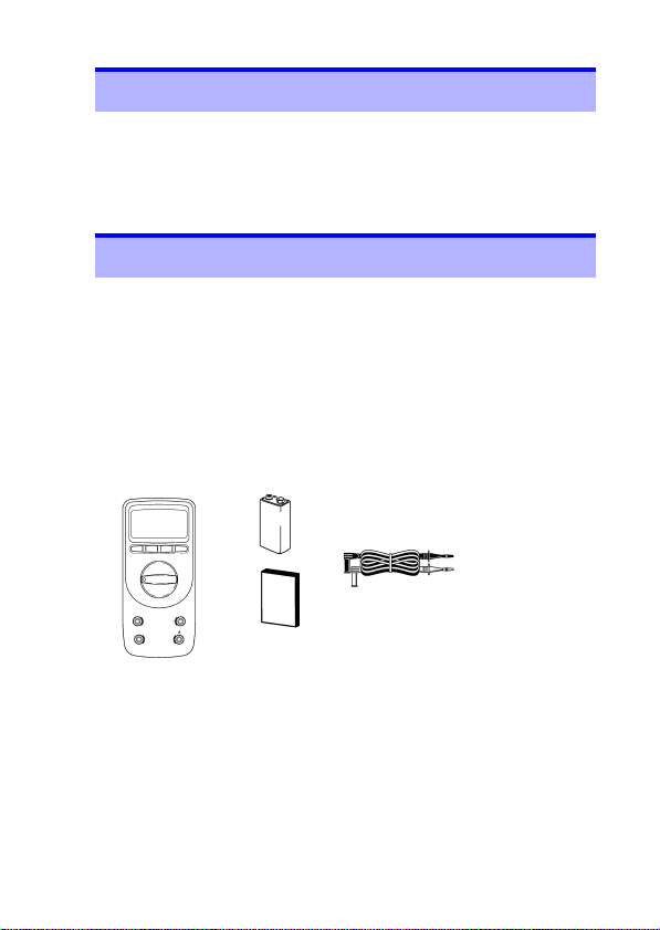
梱包内容の確認
• 本器がお手元に届きましたら、輸送中において異常または破損
がないか点検してからご使用ください。特に付属品および、パ
ネル面のスイッチ、端子類に注意してください。万一、破損あ
るいは仕様どおり動作しない場合は、お買上店(代理店)か最
寄りの営業所にご連絡ください。
• 本器を輸送するときは、最初にお届けした梱包材を使用し、必
ず二重梱包してください。輸送中の破損については保証しかね
ます。
□ 積層形アルカリ乾電池
6LR61(本体内蔵 / 1 個)
□ 3851-10 テストリード(1 個)
□ 取扱説明書(1 冊)
□ 3804-50 ディジタルハイテスタ
(ホルスタ付き / 1 台)
1
オプション
□ 3853 携帯用ケース
□ 3856-01 通信パッケージ(RS-232C)
□ 3856-02 通信パッケージ(USB)
□ 9617 台付クリップ(CE 非対応)
□ 9618 クリップ形リード(CE 非対応)
Page 6
安全について
2
安全について
この機器は IEC 61010 安全規格に従って、設計され、試験し、
安全な状態で出荷されています。測定方法を間違えると人身事故
や機器の故障につながる可能性があります。取扱説明書を熟読し、
十分に内容を理解してから操作してください。万一事故があって
も、弊社製品が原因である場合以外は責任を負いかねます。
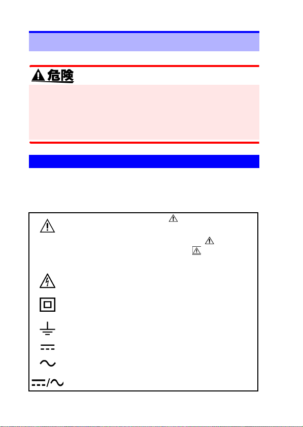
安全記号
この取扱説明書には本器を安全に操作し、安全な状態に保つの
に要する情報や注意事項が記載されています。本器を使用する
前に下記の安全に関する事項をよくお読みください。
使用者は、取扱説明書内の マークのあるところ
は、必ず読み注意する必要があることを示します。
使用者は、機器上に表示されている マークの
ところについて、取扱説明書の マークの該当
箇所を参照し、機器の操作をしてください。
この端子には、危険な電圧がかかることを示しま
す。
二重絶縁または強化絶縁で保護されている機器を
示します。
接地端子を示します。
直流(DC)を示します。
交流(AC)を示します。
直流(DC)または交流(AC)を示します。
Page 7

安全について
取扱説明書の注意事項には、重要度に応じて以下の表記がされ
ています。
操作や取り扱いを誤ると、使用者が死亡また
は重傷につながる危険性が極めて高いこと
を意味します。
操作や取り扱いを誤ると、使用者が死亡また
は重傷につながる可能性があることを意味
します。
操作や取り扱いを誤ると、使用者が傷害を負
う場合、または機器を損傷する可能性がある
ことを意味します。
製品性能および操作上でのアドバイス的な
ことを意味します。
その他の記号
してはいけない行為を示します。
3
(⇒ p. )
*
参照先を示します。
説明を下部に記述しています。
Page 8
安全について
4
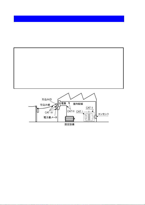
測定カテゴリ(過電圧カテゴリ)について
本器は CAT II (1000 V)、CAT III (600 V) に適合しています。
測定器を安全に使用するため、IEC61010 では測定カテゴリと
して、使用する場所により安全レベルの基準を CAT Ⅰ~ CAT
Ⅳで分類しています。概要は下記のようになります。
CAT I:
CAT II:
CAT III:
CAT IV:
数値の大きいカテゴリは、より高い瞬時的なエネルギーのある
電気環境を示します。そのため、CAT Ⅲで設計された測定器は、
CAT Ⅱで設計されたものより高い瞬時的なエネルギーに耐える
ことができます。
カテゴリの数値の小さいクラスの測定器で、数値の大きいクラ
スに該当する場所を測定すると重大な事故につながる恐れがあ
りますので、絶対に避けてください。
特に、CAT Ⅰの測定器を CAT Ⅱ、ⅢおよびⅣに該当する場所
の測定に用いないでください。
測定カテゴリは IEC60664 の過電圧カテゴリに対応します。
コンセントからトランスなどを経由した機器内の二次側
の電気回路
コンセントに接続する電源コード付き機器(可搬形工具・
家庭用電気製品など)の一次側電路
直接分電盤から電気を取り込む機器(固定設備)の一次側
および分電盤からコンセントまでの電路
建造物への引込み電路、引込み口から電力量メータおよび
一次過電流保護装置(分電盤)までの電路
Page 9
ご使用にあたっての注意
5
ご使用にあたっての注意
本器を安全にご使用いただくために、また機能を十二分にご活
用いただくために、下記の注意事項をお守りください。
本器の設置について
使用温湿度範囲 :0 ~ 40 ℃、80%rh 以下(結露しないこと)
ただし 31 ℃を超える場合、湿度は 40 ℃、
確度保証温湿度範囲:23 ± 5 ℃、80%rh 以下(結露しないこと)
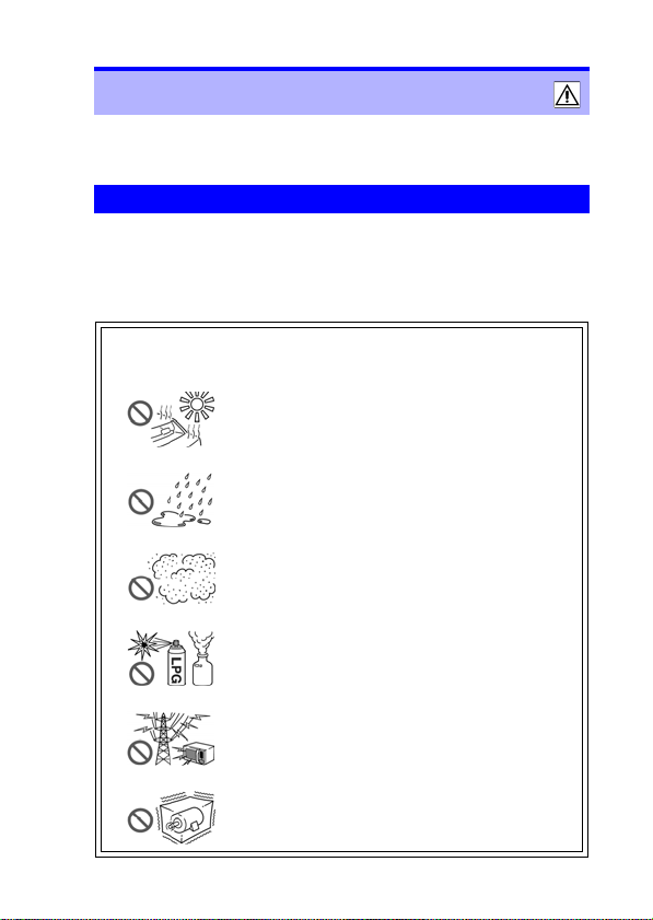
本器の故障、事故の原因になりますので、以下のような場所
には設置しないでください。
50%rh へ直線的に減少
直射日光があたる場所
高温になる場所
水のかかる場所
多湿、結露するような場所
ホコリの多い場所
腐食性ガスや爆発性ガスが発生する場所
強力な電磁波を発生する場所
帯電しているものの近く
機械的振動の多い場所
Page 10
ご使用にあたっての注意
6
ご使用前の確認
使用前には、保存や輸送による故障がないか、点検と動作確認
をしてから使用してください。故障を確認した場合は、お買上
店(代理店)か最寄りの営業所にご連絡ください。
テストリードの被覆が破れたり、金属が露出していないか、使
用する前に確認してください。損傷がある場合は、感電事故に
なるので、指定の 3851-10 テストリードと交換してください。
測定時の注意
感電事故を防ぐため、下記のことをお守りください。
• 測定前に必ずファンクションスイッチの位置を確認してくだ
さい。
• ファンクションスイッチを切り替えるときは、テストリード
を被測定物から外し、測定端子からも抜いてください。
端子部は、安全な絶縁距離がとれていません。感電事故を防ぐ
ため、端子部には触れないでください。
安全のため、テストリードは付属またはオプションの テスト
リードを使用してください。
Page 11
ご使用にあたっての注意
本器の取り扱いについて
本器の損傷を防ぐため、運搬および取り扱いの際は振動、衝撃
を避けてください。特に、落下などによる衝撃に注意してくだ
さい。
• 電池の液漏れによる腐食を防ぐため、長い間使用しな
いときは、電池を抜いて保管してください。
• 使用後は必ずファンクションスイッチをOFFにしてく
ださい。
テストリードの取り扱いについて
• 断線による故障を防ぐため、ケーブルを折ったり引っ張った
りしないでください。
• テストリードの先端はとがっているため危険です。けがのな
いよう、取り扱いには十分注意してください。また、使用し
ないときは保護用のキャップを取り付けてください。
• ケーブルが溶けると金属部が露出し危険です。発熱部などに
触れないようにしてください。
7
Page 12

ご使用にあたっての注意
8
Page 13
1.1 製品概要・特長
概要 第1章
1.1 製品概要・特長
本器は電圧(直流 / 交流)、電流( 直 流 / 交 流)、抵抗、導通、ダ
イオード、静電容量測定が可能な多機能高性能ディジタルマル
チメータです。また、オプションの 3856-01/02 でパソコンと
接続して本器の制御や測定データの送信を行うことができま
す。
高性能ハンディ DMM
最大 9999 カウント表示可能です。直流電圧測定の基本確度
は± 0.09%rdg. ± 2dgt. です。
CE マーキング対応の安全設計
国際安全規格(IEC61010-1 測定カテゴリ CAT Ⅱ 1000 V、
CAT Ⅲ 600 V)、EMC 関連規格に適合しています。
充実した付加機能
測定の簡単サポートから簡易解析までの充実した付加機能
を備えています。
参照 :「第 3 章 付加機能」(
⇒ p.27)
9
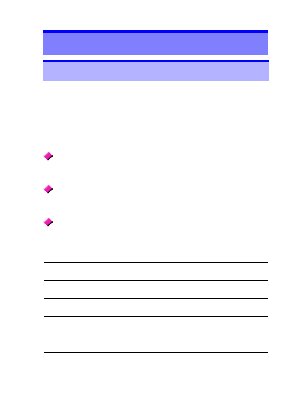
リフレッシュホール
ド機能
レコーディング機能
4-20mA(0-20mA)
% 換算表示機能
相対値表示機能 基準値からの変動を表示します。
通信機能
測定値を自動的に固定して、テストリードを離
しても測定値を保持します。
測定中の最大値、最小値、最大値 - 最小値、平
均値、現在の測定値を切り替えて表示します。
4-20 mA(0-20 mA)計装信号を 0-100% に
換算表示します。
パソコンと接続してデータを解析できます。
(RS-232C/USB、オプション 3856-01/02 が
必要です)
Page 14
1.2 各部の名称と機能
10
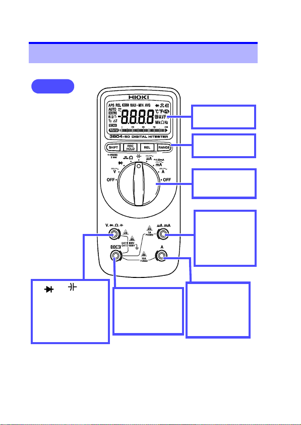
1.2 各部の名称と機能
正面図
表示部
参照 : (⇒ p.11)
キー操作部
参照 : (⇒ p.12)
ファンクション
スイッチ
参照 : (⇒ p.12)
μA.mA 端子
電流 測 定(999.9
mA 以下)で使用
する端子です。テ
ストリードの赤色
を接続します。
V. ..Ω. 端子
電圧測定、ダイオード
チェック、抵抗測定、静
電容量測定で使用する
端子です。テストリー
ドの赤色を接続しま
す。
COM 端子
各測定共通で使用
する端子です。テス
トリードの黒色を
接続します。
A端子
電流測定(9.99 A
以下)で使用する
端子です。テスト
リードの赤色を接
続します。
Page 15
1.2 各部の名称と機能
11
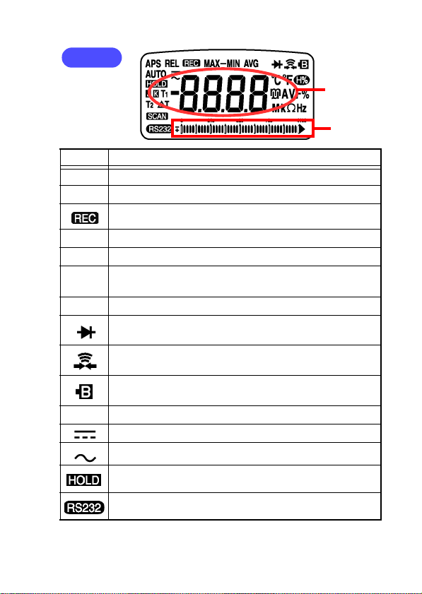
表示部
測定値表示
部と単位
バーグラフ
記号 説明
APS オートパワーセーブ機能が ON のとき点灯します。
REL 相対値表示機能が ON のとき点灯します。
レコーディング機能が ON のとき点灯します。
MAX 最大値を表示しているとき点灯します。(レコーディング機能)
MIN 最小値を表示しているとき点灯します。(レコーディング機能)
MAX-
最大値 - 最小値を表示しているとき点灯します。(レコーディ
ング機能)
MIN
AVG 平均値を表示しているとき点灯します。(レコーディング機能)
ダイオードチェックファンクションのとき点灯します。
導通チェックファンクションのとき点灯します。
バッテリマーク(電池消耗警告表示)です。
電池交換時期に点灯します。
AUTO オートレンジのとき点灯します。
DCV 測定、DCA 測定のとき点灯します。
ACV 測定、ACA 測定のとき点灯します。
マニュアル/トリガホールド機能が ON のとき点灯します。
通信制御されているとき点灯します。
Page 16
1.2 各部の名称と機能
12
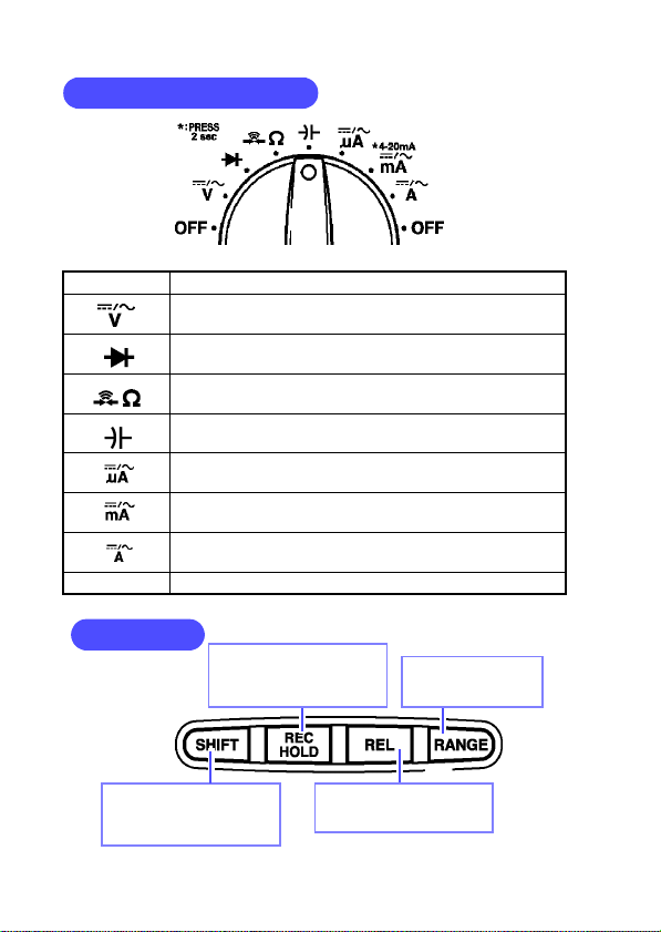
ファンクションスイッチ
OFF 本器の電源を切ります。
電圧測定ファンクションです。
SHIFTキーで DC、AC を切り替えます。
ダイオードチェックファンクションです。
抵抗測定ファンクションです。
SHIFTキーで導通チェックに切り替えます。
静電容量測定ファンクションです。
9999 μA 以下の電流測定ファンクションです。
SHIFTキーで DC、AC を切替えます。
999.9 mA 以下の電流測定ファンクションです。
SHIFTキーで DC、AC を切り替えます。
9.99 A 以下の電流測定ファンクションです。
SHIFTキーで DC、AC を切り替えます。
OFF 本器の電源を切ります。
キー操作部
ホールド機能、長押しで
レコーディング機能の
ON/OFF を行います。
レンジの切替えを
を行います。
SHIFT キーです
測定機能(本体青字表記)
の切替え等を行います。
相対値機能の ON/OFF
を行います。
Page 17
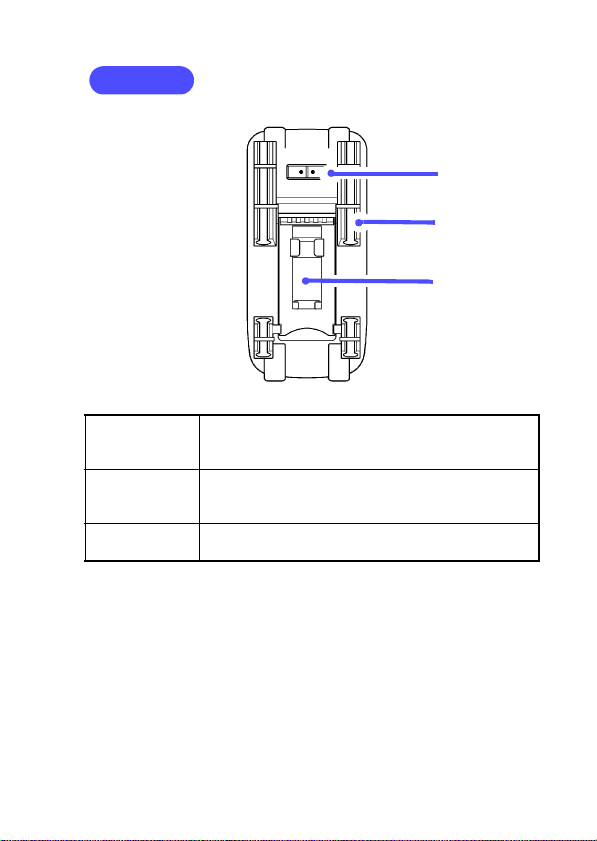
ホルスタ
1.2 各部の名称と機能
コネクタ
テストリード
ホルダ
スタンド
13
コネクタ
テストリード
ホルダ
スタンド
オプションの通信ケーブルを接続します。
ホルスタを本器から外すとコネクタも外れます。紛
失しないように注意してください。
テストリードを固定できます。
一方のテストリードを固定して、本器を持ちながら
測定することができます。
スタンドを引き出して、本器を立てて置くことがで
きます。
本器は標準付属のホルスタが装着されています。
ホルスタは柔らかい材質のため、外部からの衝撃を吸収して本
器を保護します。
電池またはヒューズは、ホルスタを外してから交換してくださ
い。また、交換後はホルスタを装着してから使用してください。
Page 18
1.2 各部の名称と機能
14
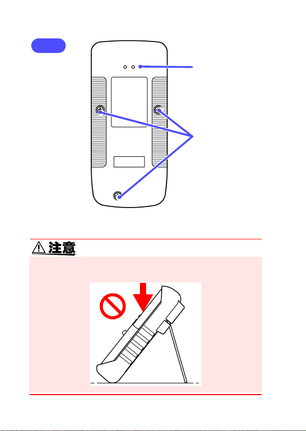
背面
通信ポート
ネジ
スタンドを立てたまま、上方向から強い力を加えないでくださ
い。スタンドを損傷します。
Page 19
15
測定方法 第2章
感電事故を防ぐため、下記のことをお守りください。
• 測定前に必ずファンクションスイッチの位置を確認してくだ
さい。
• ファンクションスイッチを切り替えるときは、テストリード
を被測定物から外し、測定端子からも抜いてください。
• 最大入力電圧は DC1000 V、AC1000 V または 2 × 10
V Hz です。この最大入力電圧を超えると本器を破損し、人
身事故になるので測定しないでください。
• 最大入力電流は以下の通りです。
A 端子:AC/DC 10 A まで連続
μA.mA 端子:AC/DC 1 A
この電流を超えると本器を破損し、人身事故になるので入力
しないでください。
• 対地間最大定格電圧は以下の通りです。
CAT Ⅱ:DC1000 V, AC1000 V
CAT Ⅲ:DC600 V, AC600 V
大地に対してこの電圧を超える測定はしないでください。本
器を破損し、人身事故になります。
• 感電事故を防ぐため、テストリードの先端で電圧のかかって
いるラインを短絡しないでください。
• テストリードによる測定箇所は、安全のため必ずブレーカの
二次側で行ってください。
7
端子部は、安全な絶縁距離がとれていません。感電事故を防ぐ
ため、端子部には触れないでください。
Page 20
2.1 測定前の点検
16
安全のため、テストリードは付属またはオプションの テスト
リードを使用してください。
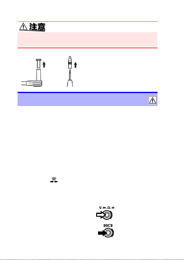
テストリードには輸送時に先ピ
ンを保護するためのキャップが
装着されています。ご使用前に取
り外してください。
2.1 測定前の点検
動作点検
動作確認をして異常があった場合は、途中でも点検を中止し、本
器を使用しないでください。
用意するもの
• 本器
• 3851-10 テストリード
• AC コンセント(AC100 V 50 Hz/ 60 Hz などの商用電源)
1. ファンクションスイッチを Ω にします。
2. SHIFT キーを押して導通チェックにします。
(点灯)
⇒ p.23)
参照 :(
3. テストリードの赤色を本器の V 端子に、黒色を
COM 端子に接続します。
赤
黒
Page 21
2.1 測定前の点検
17
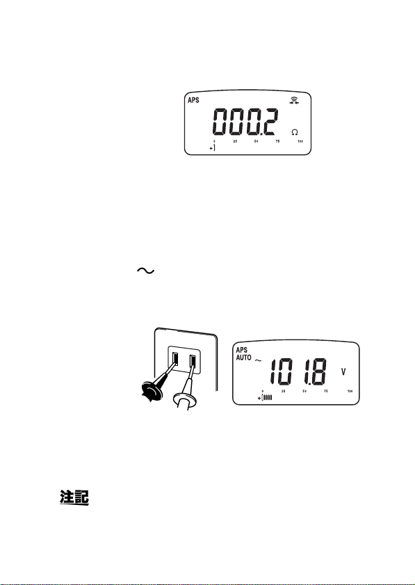
4. テストリードの赤色と黒色の先端同士を押し当て
て短絡します。
• ブザーが鳴る
• 0 Ω 付近で値が安定している
• OL を表示する / 表示が安定しない→ NG
テストリードの断線、テスタの故障が考え
られます
→ OK
5. ファンクションスイッチを V にし、SHIFT キーを
押して ACV にします。
(点灯)
6. AC コンセントの差し込み口にテストリードの先
端を差し込みます。
黒
赤
• 商用電圧値を表示する → OK
• 商用電圧値を表示しない→ NG
テスタの故障が考えられます
これは本器の動作の一部を確認するのみです。本器が製
品仕様通り動作するかの確認には、定期的な校正が必要
です。
Page 22
2.1 測定前の点検
18
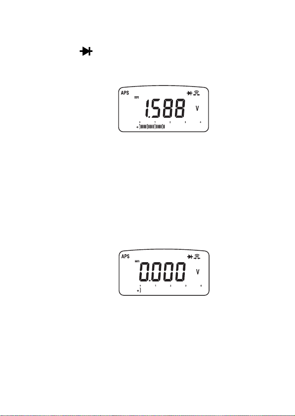
7. (μA、mA 端子用ヒューズの断線確認)
ファンクションスイッチをダイオードチェック
( )にします。
テストリードの赤色を μA、mA 端子に、黒色を V
端子に接続し、先端同士を押し当てて短絡します。
• 約 1.6 V を表示する → OK
• OL を表示する→ NG
ヒューズの断線が考えられます
ヒューズの交換をしてください
⇒ p.53)
参照 :(
8. (A 端子用ヒューズの断線確認)
テストリードの赤色を A 端子に、黒色を V 端子に
接続し、先端同士を押し当てて短絡します。
• ブザーが鳴る → OK
• OL を表示する→ NG
ヒューズの断線が考えられます
ヒューズの交換をしてください
⇒ p.53)
参照 :(
Page 23
2.2 電圧測定
19
2.2 電圧測定
• 各レンジの測定範囲を超える電圧、電流を入力しないでくだ
さい。本器を破損します。
• 本器の電源が OFF の状態で、測定端子に電圧、電流を入力し
ないでください。本器を破損することがあります。
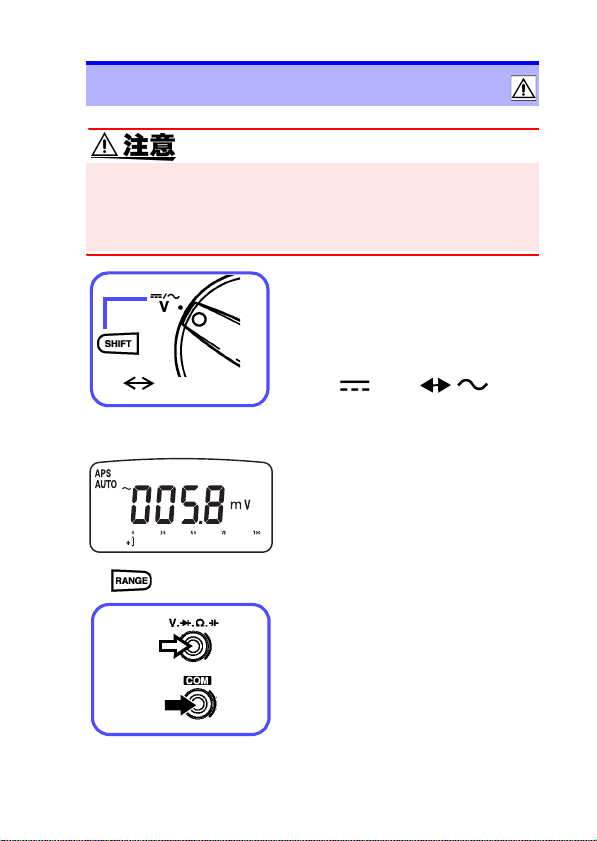
1. ファンクションスイッチを
切り替えます。
2. SHIFT キーで DC、AC を選
択します。
AC DC
<例> ACV 選択時
(AUTO 消灯)
赤
(DC)
3. マニュアルレンジにしたい
場合は RANGE キーを押し
ます。
(通常はオートレンジです)
(⇒ p.28)
4. テストリードを測定端子に
接続します。
(AC)
黒
Page 24

20
2.3 電流測定
<例>
交流電圧測定
黒
赤
直流電圧測定
黒
<例> AC 電圧測定時
赤
5. 被測定物にテストリードを
接続します。
6. 表示部の表示値を読みま
す。
2.3 電流測定
電圧を入力しないでください。本器を破損し、人身事故になり
ます。電気事故を防ぐため、測定回路の電源を切ってから、測
定してください。
• 各レンジの測定範囲を超える電圧、電流を入力しないでくだ
さい。本器を破損します。
• 本器の電源が OFF の状態で、測定端子に電圧、電流を入力し
ないでください。本器を破損することがあります。
Page 25
AC DC
<例> ACA 選択時
(AUTO 消灯)
A の場合
黒
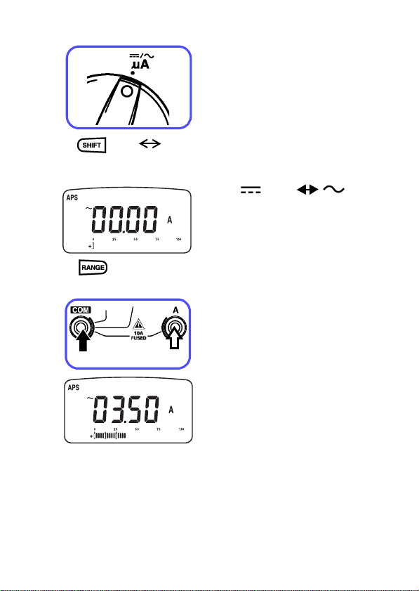
1. ファンクションスイッチを
切り替えます。
μA :9999 μA 以下を測定する
とき
mA:999.9 mA 以下を測定す
るとき
A:9.99 A以下で測定するとき
測定する電流が不明なときは、
A に合わせてください。
2. SHIFTキーで DC、AC を選
択します。
(DC)
3. マニュアルレンジにしたい
場合は RANGE キーを押し
ます。
(通常はオートレンジです)
参照 :(⇒ p.28)
4. テストリードを測定端子に
接続します。
5. 被測定物にテストリードを
赤
接続します。
6. 表示部の表示値を読みま
す。
mA ファンクションで SHIFT
キー
を長押しすると % 換算表
示(4-20 mA/ 0-20 mA)にな
ります。工業計器のチェックに
使用できます。
参照 :(⇒ p.33)
2.3 電流測定
21
(AC)
Page 26
2.4 抵抗測定
22
2.4 抵抗測定
電圧を入力しないでください。本器を破損し、人身事故になり
ます。電気事故を防ぐため、測定回路の電源を切ってから、測
定してください。
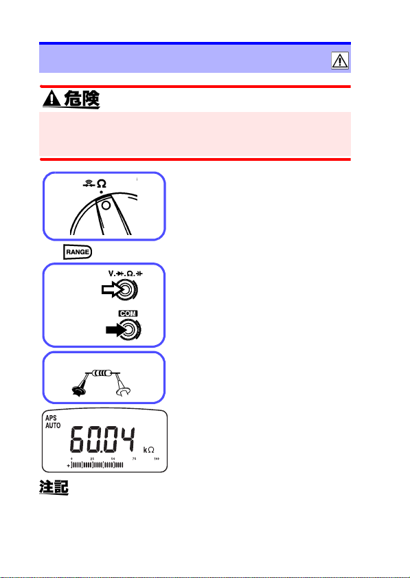
1. ファンクションスイッチを
切り替えます。
2. マニュアルレンジにしたい
場合は RANGE キーを押し
ます。
(通常はオートレンジです)
参照 :(⇒ p.28)
3. テストリードを測定端子に
接続します。
4. 被測定物にテストリードを
接続します。
5. 表示部の表示値を読みます。
<例>
黒
(AUTO 消灯)
赤
黒
赤
• 相対値表示機能(REL) でゼロアジャストすることがで
きます。参照:(⇒ p.32)
• インダクタンスが 10H(ヘンリー)を超えるようなコ
イル(インダクタ)の巻線抵抗は、誘導負荷の影響で
測定できない場合がありますのでご注意ください。
Page 27
2.5 導通チェック
23
2.5 導通チェック
電圧を入力しないでください。本器を破損し、人身事故になり
ます。電気事故を防ぐため、測定回路の電源を切ってから、測
定してください。
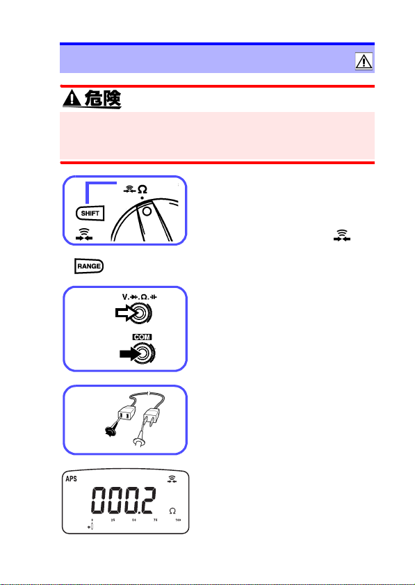
1. ファンクションスイッチを
切り替えます。
点灯
<例>
(AUTO 消灯)
赤
黒
黒
2. SHIFTキ ーで 導通( )を
選択します。
3. レンジを変更したい場合は
RANGE キーを押します。
(通常はマニュアルレンジです)
オートレンジにしたい場合は
RANGE キーを長押しします。
参照 :(⇒ p.28)
4. テストリードを測定端子に
接続します。
5. 被測定物にテストリードを
接続します。
赤
6. 表示部の表示値を読みます。
各レンジで表示値が 100 カウン
ト以下の場合、ブザー音が鳴り
ます。(999.9 Ω レンジの場合
10.0 Ω 以下)
ただし、相対値表示モード中は
表示値ではなく内部の測定値に
従います。
Page 28
2.6 ダイオードチェック
24
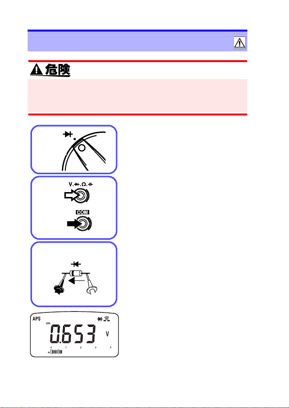
2.6 ダイオードチェック
電圧を入力しないでください。本器を破損し、人身事故になり
ます。電気事故を防ぐため、測定回路の電源を切ってから、測
定してください。
1. ファンクションスイッチを
切り替えます。
<例>
カソード
赤
黒
アノード
順方向
黒
赤
2. テストリードを測定端子に
接続します。
3. 被測定物にテストリードを
接続します。
4. 表示部の表示値を読みます。
正常なダイオードで順方向電圧
(0.3 ~ 0.8 V)を表示します。
表示値が 0.050 V 未満の場合、
ブザー音が鳴ります。
表示値が 0.3 V ~ 0.8 V に下が
ると、ダイオード検出としてブ
ザー単発音が鳴ります。
ただし、相対値表示モード中は
表示値ではなく内部の測定値に
従います。
Page 29
2.7 コンデンサ容量測定
25
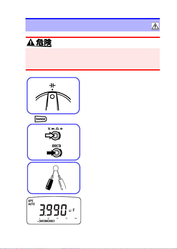
2.7 コンデンサ容量測定
電圧を入力しないでください。本器を破損し、人身事故になり
ます。電気事故を防ぐため、測定回路の電源を切ってから、測
定してください。
1. ファンクションスイッチを
切り替えます。
2. マニュアルレンジにしたい
(AUTO 消灯)
赤
黒
<例>
場合は RANGE キーを押し
ます。
(通常はオートレンジです)
参照 :(⇒ p.28)
3. テストリードを測定端子に
接続します。
4. 被測定物にテストリードを
接続します。
5. 表示部の表示値を読みます。
本器は充放電方式により、コン
デンサ容量を測定します。9.999
mF レンジは、充電時間の影響
で測定値が表示されるまで数十
秒程度かかる場合があります。
Page 30

2.7 コンデンサ容量測定
26
Page 31

3.1 オートレンジ機能
27
付加機能 第3章
3.1 オートレンジ機能
オートレンジ機能は、最適なレンジを自動で選択して測定しま
す。入力信号の大きさがわからないときや、レンジ設定の手間
を省きたいときに使用します。
導通チェック以外のファンクションでは、電源を入れるとオー
トレンジになります。(画面に「AUTO」が点灯します)
AUTO 点灯
しきい値
レンジ アップ ダウン フルスケール
1 9999 レンジ 9999 超 900 未満 9999
2 9.99 A レンジ - - 999
3 2.100 V レンジ - - 2100
• 導通チェックファンクションでは、初期設定がマニュ
アルレンジになります。
• ダイオードチェック、A ファンクションにはオートレ
ンジはありません。
Page 32

3.2 マニュアルレンジ機能
28
3.2 マニュアルレンジ機能
キーを押すとマニュアルレンジになります。キーを押すごとに
レンジアップし、小数点の位置が変わります。入力信号の大き
さがあらかじめわかっているときに使用します。
オートレンジにしたいときは、RANGEキーを長押しします。
AUTO 消灯
• 導通チェックの初期設定はマニュアルレンジです。導通チェッ
ク以外のファンクションでは、初期設定がオートレンジになり
ます。
• ダイオードチェック Aファンクションにはオートレンジはあり
ません。
3.3 ホールド機能
3.3.1 トリガホールド機能
トリガホールド機能は、REC/HOLD キーを押す毎に、測定値を
固定します。
1. リフレッシュホールド機能を OFF にします。
参照 :(
⇒ p.40)
2. 測定時に REC/HOLD キーを押すと、表示値を固定
します。
Page 33

3.3 ホールド機能
29
3. REC/HOLDキーを押すごとに表示値を更新して固
定します。
HOLD 点灯
HOLD 点滅→点灯
トリガホールドを解除するときは、REC/HOLD
キーを長押しします。
バーグラフは表示値に従い固定されます。
3.3.2 リフレッシュホールド機能
リフレッシュホールド機能は、測定値が安定すると自動的に表
示値を固定します。テストリードを被測定物から離しても表示
値は固定されたままのため、測定場所から表示値が見づらいと
きや両手で測定しているときに便利な機能です。
1. リフレッシュホールド機能のしきい値(表示が安
定したと判断する変化量)を設定します。
参照 :(
⇒ p.40)
2. REC/HOLD キーを押すと、トリガ待ち状態になり
ます。
Page 34

3.3 ホールド機能
30
3. 測定対象にテストリードを接続します。表示値が
安定すると が点灯し、ブザー音が鳴り表示が
固定されます。
HOLD
HOLD 点滅
トリガ待ち状態
4. ブザー音を確認後、テストリードを測定対象から
離します。
表示値は固定されたまま、 が点滅し、再びト
リガ待ち状態になります。
REC/HOLD キーを長押しすると、リフレッシュ
ホールド機能を解除します。
• バーグラフは入力信号に従います。
• 表示値が限度感度値
*
ません。表示値がうまく固定されないときは、しきい
値を変更してみてください。
⇒ p.40)
参照 : (
* 限度感度値は各ファンクションで以下のようになっています。
ファンクション 限度感度値
DCV/DC
μ
A/DCmA 各レンジ 100 カウント
μ
ACV/AC
A/ACmA 各レンジ 500 カウント
DCA 0.1 A
ACA 0.5 A
Ω
HOLD
を超えないと表示値は固定され
OL
Page 35

3.4 レコーディング機能
31
3.4 レコーディング機能
レコーディング機能開始からの入力信号の最大値、最小値、最大値 - 最小
値、平均値を記録します。
入力信号の現在値 :REC
入力信号の最大値 :REC MAX
入力信号の最小値 :REC MIN
入力信号の最大値 - 最小値:REC MAX-MIN
入力信号の平均値 :REC AVG
1. 測定時に REC/HOLDキーを長押しすると、レコー
ディング機能が開始します。
REC 点灯
現在値表示
2. REC/HOLD
- 最小値、平均値、現在値と表示部が切り替わります。
最大値(最小値)を更新するとブザー音が鳴ります。
キーを押す度に最大値、最小値、最大値
MAX 点灯
最大値表示
MAX
MIN
MAX-MIN
AVG
現在値
3. REC/HOLD キーを長押しすると、レコーディング
機能を解除します。
• レコーディング機能では、表示値ではなく、平滑する
前の内部測定データに対して最大値、最小値、平均値
を記録します。
• レコーディング機能では、オートパワーセーブ機能は
自動的に無効になります。
• バーグラフは現在値を示します。
Page 36

3.5 相対値(REL)表示機能
32
3.5 相対値(REL)表示機能
REL キーを押すと、現在の表示値を基準値として、その相対値
を表示します。
電圧(mV)測定、抵抗測定などで測定前にテストリードを短絡
して相対値表示モードにすることで、ゼロアジャスト機能とし
て利用できます。(熱起電力や配線抵抗の影響をキャンセルしま
す)
1. 基準値にしたい測定値を表示します。
2. REL キーを押すと、現在の表示値を基準値として、
その相対値を表示します。
相対値 - 測定値 - 基準値
• バーグラフは表示する相対値に従います。
• 表示が「OL」の場合は、相対値(REL) 表示機能は動
作しません。
Page 37

3.6 4-20 mA(0-20 mA)% 換算表示機能
%
33
3.6 4-20 mA(0-20 mA)% 換算表示
機能
4-20 mA(0-20 mA)% 換算表示機能は、計装システムの 420 mA(または 0-20 mA)信号を 0% ~ 100% に換算して表
示します。
4-20 mA (測定電流 12.00 mA時)
0-20 mA (測定電流 12.00 mA 時)
% 換算値=
測定値 [mA] - 4[mA]
換算値=
16[mA]
測定値 [mA]
20[mA]
×100[%]
×100[%]
パワーオン
オプション
1. パワーオプションの 4-20 mA(0-20 mA)% 換算
表示で 4-20 mA%表示か 0-20 mA 表示を選択しま
す。参照:(
⇒ p.40)
2. mA ファンクションで SHIFT キーを長押しすると
4-20 mA(0-20 mA)% 換算表示機能が起動します。
3. SHIFT キーを再び長押しすると 4-20 mA(0-20
mA)% 換算表示機能を解除します。
4. RANGE キーで 4-20 mA(0-20 mA)% 換算表示の
レンジが切り替わります。
レンジ 999.9% 9999%
• バーグラフは入力信号の電流値に従います。
• 測定画面で4-20 mAか 0-20 mAかを判断できないた
め、パワーオンオプションで確認してください。
⇒ p.40)
参照 :(
Page 38

3.7 バーグラフ表示機能
34
3.7 バーグラフ表示機能
測定値に応じてバーが点灯し、直感的に入力レベ
ルが確認できます。測定機能に応じてスケール(目
盛)を表示します。また極性に応じて±符号を表
示します。
バー
スケール
100
バー
スケール
4
3.8 オートパワーセーブ機能
ファンクションスイッチまたはキーの最終操作から設定時間が経
過するとオートパワーセーブ機能が動作します。オートパワーセー
ブ機能により表示画面が消灯し、本体内部の電源消費を抑えます。
APS 点灯
1. パワーオンオプションで動作時間を設定します。
機能を無効にすることもできます。
参照 :(
⇒ p.40)
2. オートパワーセーブ機能から復帰するには、ロー
タリスイッチを一度 OFF するか、何かキーを押し
ます。
• レコーディング機能では、オートパワーセーブ機能は
無効になります。
• オートパワーセーブ機能を無効にした場合は、電源の
切り忘れに注意してください。
Page 39

3.9 過負荷警告機能
35
3.9 過負荷警告機能
電圧測定で入力電圧が 610.0 V を超えると、断続的なブザー音
で警告します。ただちにテストリードを被測定物から外してく
ださい。
ピッピッピ…
ブザー断続音
各レンジでフルスケールを超えると「OL」を表示しま
す。オートレンジにするか最適なレンジを選択してくだ
さい。
⇒ p.27)(⇒ p.28)
参照 : (
レンジ フルスケール
9999 カウントレンジ 9999
9.99 A レンジ 9.99 A
2.100 V カウントレンジ 2.100 V
Page 40

3.10 電池寿命警告機能
36
3.10 電池寿命警告機能
点滅
• 電池交換時期(約6.2 V以下)になると測定画面にバッテリマー
ク( )が表示されます。電池を交換してください。
• バッテリマーク( )が表示されてもしばらくは測定値を表
示しますが、バッテリマーク( )点灯中は確度仕様を満足
しませんので、速やかに電池を交換してください。
⇒ p.53)
参照 :(
3.11 通信機能(オプション)
本器は、RS-232C インターフェースを利用したデータの送信機
能を装備しています。パソコンと本器を接続して、測定データ
を本器からパソコンに転送し、データの記録と保存ができます。
この機能を利用するには、下記の別売りオプションが必
要です。使用するパソコンに合わせてご購入ください。
• パソコン側シリアルポート(D-sub9pin)に接続する
場合
3856-01 通信パッケージ(RS-232C)
• パソコン側 USB ポートに接続する場合
3856-02 通信パッケージ(USB)
参照 : 3856-01、3856-02 取扱説明書
1. パソコンにソフトウェアをインストールします。
参照 :3856-01、3856-02 取扱説明書
Page 41

3.11 通信機能(オプション)
37
2. 本器の通信設定は以下となっています。必要に応
じてパソコン側の設定を行ってください。
ボーレート 9600
パリティチェック なし
データ長 8 bit
3. 付属のソフトウェアで通信する場合は、本器のパ
ワーオンオプションで以下のように設定してくだ
さい。(
⇒ p.40)
応答 OFF
データ出力 OFF
4. 3856-02 通信パッケージを使用する場合は、パ
ソコンに付属のドライバをインストールします。
5. 通信ケーブルの光コネクタ側を本体ホルスタのコ
ネクタ部に接続します。
「RS-232C INTERFACE」の
文字を上に向ける
「RS-232C INTERFACE」の文字を下に向けると通信で
きません。
6. 通信ケーブルのもう一方のコネクタをパソコンに
接続します。
7. ソフトウェアを実行します。本器からパソコンに
測定データが送信されます。
Page 42

3.11 通信機能(オプション)
38
コネクタを本器から外す場合はツメを押しながら引き
抜きます。
ツメ
Page 43

パワーオンオプション 第4章
測定機能、付加機能の各種設定を行います。
操作方法
SHIFT +電源 ON
設定項目の選択
設定値(パラメータ)の選択
設定値(パラメータ)の確定
1. SHIFT キーを押しながらファンクションスイッチ
をOFFから回して電源を入れると設定画面となり
ます。
2. SHIFT キーを押して設定項目を選択します。
3. REC/HOLD キーまたは REL キーを押して設定値
(パラメータ)を選択します。(現在設定されてい
る値以外は表示が点滅します。)
4. RANGE キーを押して設定値(パラメータ)を確定
します。
5. 設定が完了したらファンクションスイッチを OFF
します。(または、RANGE キーを長押しすると通
常の測定画面に戻ります。)
39
Page 44

40
設定項目一覧
設定項目 設定画面 機能
通信機能:応答の設定
応答
データ出力
4-20mA
(0-20mA)%
換算表示
ブザー音
リフレッシュ
ホールド
オートパワー
セーブ
応答を ON にすると通信機能で本器
が受信した文字を全て返信します。
(設定項目)OFF(初期値)/ ON
通信機能:データ出力の設定
データ出力を ON にすると通信機能
で本器からサンプリング毎にデータ
のみを出力します。
(設定項目)OFF(初期値)/ ON
4-20 mA(0-20 mA)% 換算表示機
能の 4-20 mA と 0-20 mA表示の切
り替えを行います。
(設定項 目):4-20 mA%(初期値)
/0-20 mA%
ブザー音を好みの音色または消音に
設定できます。
(設定項目)2400 Hz(初期値)/300
Hz/ 600 Hz/1200 Hz/OFF(消音)
リフレッシュホールド機能のしきい
値(表示が安定したと判断する変化
量)を設定します。OFF を選択する
とリフレッシュ機能を無効にしま
す。(トリガホールド機能が有効)
(設定項目)OFF(初期値)
/100 ~ 1000(100 毎に設定)
オートパワーセーブ機能が動作する
までの時間を設定します。
(設定項目)15m(初期値)
/1m ~ 99m/OFF
表示
バックライト
※設定はできますが、本器にはバッ
クライト機能はありません。
Page 45

AC/DC
起動選択
初期化
41
電圧ファンクション、または電流測
定ファンクションにしたときに、DC
(直流)から起動するか、AC(交流 )
から起動するかを選択します。
DC:DC(直流)から起動
AC:AC(交流)から起動
例えば、交流測定の使用頻度が高い場
合は、ACに設定しておくと便利です。
(設定項目)DC(初期値)/AC
全ての設定項目を初期値にリセット
します。
設定画面で RENGE キーを押すと、ブ
ザーが2回鳴り初期化されます。
(設定項目)DEFA(初期値)
Page 46

42
パワーオンオプション設定画面一覧
SHIFT キーを押す毎に設定画面が切り替わります。
応答
オートパワー
セーブ
表示
バックライト
データ出力
リフレッシュ
ホールド
AC/DC
起動選択
4-20 mA
(0-20 mA)%
換算表示
ブザー音設定
初期化
Page 47

5.1 一般仕様
仕様 第5章
5.1 一般仕様
• 直流電圧
• 交流電圧
• 直流電流
測定機能
付加機能
交流測定方式 平均値整流測定方式
表示方式 TN 型液晶表示体 1/4Duty ダイナミック駆動方式
表示
• 交流電流
• 抵抗
• 導通
• ダイオード
• 静電容量
• オートレンジ機能(AUTO)
• マニュアルレンジ機能
• トリガホールド機能( )
• リフレッシュホールド機能( )
• レコーディング機能(REC:MAX、MIN、AVG)
• 相対値表示機能(REL)
• 4-20 mA(0-20 mA)% 換算表示機能
• バーグラフ表示機能
• オートパワーセーブ機能(APS)
• 過負荷警告機能
• 電池寿命警告機能( )
• 通信機能(RS-232C、USB)
• データ表示
4 桁
最大カウント [9999]
最大カウント [999] 10 A レンジ
極性表示 [-] マーク自動点灯
オーバレンジ表示 [OL] または [-OL]
• バーグラフ
スケール表示、41 ドットバー表示、±極性表示
• 単位、記号
μ
][A][V][F][%][M][k][Ω][APS]
[m][
[REL][REC][MAX][-][MIN][AVG][ ][ ][ ]
[AUTO][ ][ ][ ][RS232]
HOLD
HOLD
HOLD
43
Page 48

5.1 一般仕様
44
レンジ切り替え オートレンジまたはマニュアルレンジ
入力端子 V.Ω....、COM、μA.mA、A
ファンクション
構成
キー入力構成 SHIFT、REC HOLD、REL、RANGE
電池寿命警告
電圧
電源
寸法
質量 約 390 g(ホルスタ、電池を含む)
使用場所 屋内使用、汚染度 2、使用高度 2000 m まで
使用温湿度範囲
保存温湿度範囲 -20 ℃~ 60 ℃、80%rh 以下(結露なし)
保証期間 3 年間(測定確度は除く)
付属品
交換部品
オプション
適合規格
OFF、V、 、Ω、、μA、mA、A、OFF
6.2 V ± 0.2 V 以下の時 マーク点滅
積層形マンガン乾電池(6F22)× 1 または
積層形アルカリ乾電池(6LR61)× 1
約 83W × 178H × 58Dmm
(ホルスタあり、突起部を含まず)
約76W×167H×33Dmm
(ホルスタなし、突起部を含まず)
0 ℃~ 40 ℃、80%rh 以下(結露なし)
ただし 31 ℃を超える場合、湿度は 40 ℃、50%rh
へ直線的に減少
3851-10 テストリード
ホルスタ(本体装着)
取扱説明書
積層形アルカリ乾電池(6LR61)× 1(本体内蔵モ
ニタ用)
μA.mA 端子用 1 A/700 V ヒューズ
(遮断容量 50 kA、SIBA 社製速断型
φ6.35 × 32 mm 7012540)
A 端子用 10 A/600 V ヒューズ
(遮断容量 10 kA、バスマン社製速断型
φ6.35 × 25.35 mm TDC600)
3853 携帯用ケース
3856-01 通信パッケージ(RS-232C)
3856-02 通信パッケージ(USB)
9617 台付クリップ(CE 非対応)
9618 クリップ形リード(CE 非対応)
安全性 EN61010
EMC EN61326
Page 49

5.2 電気的特性
5.2 電気的特性
45
ノイズ除去
NMRR
ノイズ除去
CMRR
応答時間
(オートレンジ)
耐電圧
最大入力電圧
最大入力電流
対地間最大定
格電圧
定格電源電圧 DC9.0 V
最大定格電力 70 mVA(Max)…電源電圧 DC9.0 V
APS 時電力 0.2 mVA(Max)…電源電圧 DC9.0 V
連続使用時間
DCV…60 dB 以上(50 Hz / 60 Hz)
DCV…120dB 以上
(DC / 50 Hz / 60 Hz、1kΩunbalance)
ACV…60dB 以上
(DC / 50 Hz / 60 Hz、1kΩunbalance)
DCV…1.2s 以内(0V → 200 V オートレンジ動作)
ACV…2.2s 以内(0 V → 200 V オートレンジ動作)
Ω …2.0s 以内(無限大→ 0 Ω オートレンジ動作)
Ω …10.0s 以内(0 Ω → 50 MΩ オートレンジ動作)
入力端子 - ケース間
AC5.312 kV 正弦波(50 Hz / 60 Hz、15 秒)
V 端子…DC1000 V / AC1000 V
または2×10
測定カテゴリⅡ 1000 V、Ⅲ 600 V、
予想される過渡過電圧 6000 V
A 端子…DC10 A / AC10 A
μA.mA 端子…DC1000 mA / AC1000 mA
CAT Ⅱ…DC1000 V / AC1000 V
CAT Ⅲ…DC600 V / AC600 V
約 30 時間(DCV 測定、マンガン乾電池使用時)
約 60 時間(DCV 測定、アルカリ乾電池使用時)
7
V・Hz
Page 50

5.3 確度
46
5.3 確度
弊社では測定値の限界誤差を、次に示す f.s.(フルスケール)、
rdg.(リーディング)、dgt.(デジット)に対する値として定義
しています。
rdg.(読み値、表示値、指示値)
現在測定中の値、測定器が現在指示している値を表します。
dgt.(分解能)
ディジタル測定器における最小表示単位、つまり最小桁の "1" を
表します。
確度保証電源
電圧範囲
確度保証温湿度
10.2 V から マーク点灯まで
23 ℃± 5 ℃、80%rh 以下(結露なし)
範囲
確度保証期間
1年間
温度特性 測定確度× 0.15 /℃を加算(上記範囲以外)
DC V(直流電圧)
レンジ 確度
999.9 mV
9.999 V
99.99 V
999.9 V
± 0.09%rdg.
±5 dgt.
± 0.09%rdg.
±2 dgt.
± 0.09%rdg.
±2 dgt.
±0.2%rdg.
±5 dgt.
入力
インピーダンス
11.11 MΩ
±1%
10.10 MΩ
±1%
10.01 MΩ
±1%
10.00 M
Ω
±1%
過負荷保護
DC1000 V / AC1000 V
または 2 × 10⁷V・Hz
過渡過電圧 6000 V
表示更新レート:7 回/ s
Page 51

5.3 確度
AC V(交流電圧)
レンジ
999.9 mV
9.999 V
99.99 V
999.9 V
表示更新レート:7 回/ s
*1 レンジの 5% 以上で確度規定
40-
200Hz
±2.5%rdg
±5dgt.
±1.2%rdg.
±5dgt.
±1.2%rdg.
±5dgt.
±1.2%rdg.
±5dgt.
確度
*1
200-
500Hz
規定なし
±1.5%rdg.
±5dgt.
±1.5%rdg.
±5dgt.
±1.5%rdg.
±5dgt.
入力
インピーダンス
11.11 MΩ ±1%
100 pF 以下
10.10 MΩ ±1%
100 pF 以下
10.01 MΩ ±1%
100 pF 以下
10.00 MΩ ±1%
100 pF 以下
過負荷保護
DC1000 V /
AC1000 V
または
2×10 7V・Hz
過渡過電圧
6000 V
ダイオード
レンジ 確度 測定電流 開放電圧 過負荷保護
DC1000 V/ AC1000 V
2.100 V
±0.3%rdg.
±2 dgt.
約0.46 mA
DC3.5 V
以下
または
2×10⁷ V・Hz
1 分間印加
過負荷時電流
0.3 A 以下
導通しきい値:0.050 V 未満でブザー音鳴る、0.3 V ~ 0.8 V の範囲の
ダイオード順方向電圧に対し単発音鳴る
表示更新レート:14 回/ s
誘導性負荷:10H まで影響なし
47
Page 52

5.3 確度
48
抵抗 Ω /導通
レンジ 確度 測定電流 開放電圧 過負荷保護
9.999
MΩ
99.99
MΩ
±0.3%rdg.
±3 dgt. *1
±0.3%rdg.
±3 dgt. *1
±0.3%rdg.
±3 dgt.
±0.3%rdg.
±3 dgt.
±0.8%rdg.
±3 dgt.
±1.2%rdg.
±3 dgt. *2
でブザー音鳴る
999.9 Ω
9.999 kΩ
99.99 kΩ
999.9 kΩ
導通しきい値:各レンジ 100 カウントに相当する抵抗値(± 5%)以下
表示更新レート:14 回/ s
誘導性負荷:10H まで影響なし
約0.46 mA
約 155 μA
約 15.5 μA
約 1.55 μA
約141 nA
約141 nA
DC3.5 V 以下
DC1000 V /
AC1000 V
または
2×10⁷ V・Hz
1 分間印加
過負荷時電流
0.3 A 以下
*1 999.9Ω、9.999kΩ レンジの確度はテストリードを短絡して相対値
表示機能(REL)実行時
*2 湿度 60%rh 以下に対して規定
静電容量 C
レンジ 確度 充電電流 過負荷保護
9.999 μF
99.99 μF
999.9 μF
mF
9.999
±2%rdg.
±5 dgt.
±2%rdg.
±5 dgt.
±3.5%rdg.
±5 dgt.
±3.5%rdg.
±5 dgt.
約0.08 mA
約0.08 mA
約0.8 mA
約0.8 mA
DC1000 V / AC1000 V
または
2×10⁷ V・Hz
1 分間印加
過負荷時電流 0.3 A 以下
表示更新レート:4 回/ s(100μF 以下)
測定方式:DC 電流による充放電方式
Page 53

5.3 確度
直流電流 DCA
レンジ 確度 負荷電圧 シャント抵抗 過負荷保護
999.9 μA
9999 μA
99.99mA
999.9mA
9.99 A
±0.1%rdg.
± 3 dgt.
±0.1%rdg.
± 3 dgt.
±0.2%rdg.
± 3 dgt.
±0.2%rdg.
± 3 dgt *1
±0.5%rdg.
± 3 dgt
0.11 V
1.1 V
0.17 V
2.0 V
0.2 V
100
100 Ω
1 Ω
1 Ω
0.01 Ω
Ω
1 A/700 V ヒューズ
遮断容量 50 kA
10 A/600 V ヒュー
ズ遮断容量 10 kA
表示更新レート:7 回/ s
*1 400 mA 以上の確度は± 0.5%rdg. ± 3dgt.
交流電流 ACA
レンジ
999.9 μA
9999 μA
99.99 mA
999.9 mA
9.99 A
確度 *1
40-500Hz 500-2kHz
±1.2%rdg.
± 5 dgt.
±1.2%rdg.
± 5 dgt.
±1.2%rdg.
± 5 dgt.
±1.2%rdg.
± 5 dgt.
±1.2%rdg.
± 5 dgt.
±1.5%rdg.
± 5 dgt.
±1.5%rdg.
± 5 dgt.
±1.5%rdg.
± 5 dgt.
±1.5%rdg.
± 5 dgt.
±1.5%rdg.
± 5 dgt.
負荷電圧シャン
ト抵抗
0.11 V 100 Ω
1.1 V 100 Ω
0.17 V 1 Ω
2.0 V 1 Ω
0.2 V 0.01 Ω
過負荷保護
1 A/700 V
ヒューズ遮断
容量 50 kA
10A/600V
ヒューズ遮断
容量 10 kA
表示更新レート:7 回/ s
*1 レンジの 5% 以上で確度規定
49
Page 54

50
5.3 確度
Page 55

6.1 困ったときは
51
保守・サービス 第6章
6.1 困ったときは
• 故障と思われるときは、「修理に出される前に」(⇒ p.52) を確
認してから、お買上店(代理店)か最寄りの営業所にご連絡
ください。
• 本器の調整や修理は、危険を良く知った技能者の責任で行っ
てください。
• 本器を輸送するときは、輸送中に破損しないように梱包し、故
障内容も書き添えてください。輸送中の破損については保証
しかねます。
• 改造は絶対にしないでください。また修理技術者以外の人は、
分解や修理をしないでください。火災や感電事故、けがの原
因になります。
• 本器の保護機能が破損している場合は、使用できないように
廃棄するか、知らないで動作させることのないように、表示
しておいてください。
本器の確度維持あるいは確認には、定期的な校正が必要です。
修理・校正業務のご用命は、「日置エンジニアリングサービス
(株)」までお願いいたします。(TEL 0268-28-0823、FAX
0268-28-0824)
長期間(1 年以上)保管した場合、本器が規定している仕様が
満足できなくなります。使用するときには本器の校正をご依頼
ください。
Page 56

6.1 困ったときは
52
修理に出される前に
動作がおかしいとき、以下の項目をチェックしてください。
症状 チェック項目 参照ページ
電池が消耗していませんか?
→ 電池を交換してください。
画面に表示が
でない
画面の表示が
しばらくする
と消える
表示が一部表
示されない
電流測定でき
ない
通信できない
電池スナップのケーブルが断線してい
ませんか?
→ お買上店(代理店)か最寄りの営業
所にご連絡ください。
電池が消耗していませんか?
→ 電池を交換してください。
オートパワーセーブ機能が動作してい
ませんか?
→オートパワーセーブの設定を確認し
てください。
全点灯表示で表示欠けがありますか?
→修理
ヒューズが断線していませんか?
ヒューズの断線確認をしてください。
ヒューズを交換してください。
テストリードが断線していませんか?
→本器の導通チェックでテストリード
の導通チェックをしてください。断
線の場合、テストリードを交換して
ください。
本器とパソコンの通信設定は問題あり
ませんか?
通信ケーブルは正しく接続されていま
すか?
その他、原因が分からない場合はシステムリセットをしてみて
ください。各種設定条件が工場出荷時の初期設定状態になりま
す。
(⇒ p.41)
参照 :
(⇒ p.53)
(⇒ p.53)
(⇒ p.34)
(⇒ p.55)
(⇒ p.18)
(⇒ p.53)
(⇒ p.23)
(⇒ p.36)
Page 57

6.2 クリーニング
53
6.2 クリーニング
本器の汚れをとるときは、柔らかい布に水か中性洗剤を少量含
ませて、軽くふいてください。ベンジン、アルコール、アセト
ン、エーテル、ケトン、シンナー、ガソリン系を含む洗剤は絶
対に使用しないでください。変形、変色することがあります。
表示部は乾いた柔らかい布で軽く拭いてください。
6.3 電池およびヒューズの交換
• 感電事故を避けるため、ファンクションスイッチをOFF にし、
テストリードを外してから電池を交換してください。 交換後
は、必ずカバーをしてから、ネジ留め後に使用してください。
• 極性+-に注意し、逆挿入しないでください。性能劣化や液
漏れの原因になります。また必ず指定の電池と交換してくだ
さい。
• 使用済の電池をショート、充電、分解または火中への投入は
しないでください。破裂する恐れがあり危険です。
• 使用済の電池は地域で定められた規則に従って処分してくだ
さい。
• 感電事故を避けるため、ファンクションスイッチを OFF にし、
テストリードを外してからヒューズを交換してください。 交換
後は、必ずカバーをしてから、ネジ留め後に使用してください。
• ヒューズは、指定された形状と特性、定格電流、電圧のもの
を使用してください。指定以外のヒューズを用いたりヒュー
ズホルダを短絡して使用すると、人身事故になるので注意し
てください。
(指定ヒューズは次ページ参照)
バッテリマーク( )点灯時は、電池が消耗していま
すので、早めに交換してください。
Page 58

6.3 電池およびヒューズの交換
54
用意するもの:プラスドライバー
ネジ
指定ヒューズ
電池
ヒューズ
1. テストリードを本器から外
し、ファンクションスイッチ
をOFFにします。
2. 本器からホルスタを外しま
す。
3. プラスドライバで下ケース
のネジを外します(3か所)。
次に下ケースを外します。
(下側から外します。上側は
つめで勘合しています。)
4. 電池(6F22(マンガン)ま
たは 6LR61(アルカリ))、
またはヒューズを交換しま
す。
μA.mA 端子用 :1 A/700 V ヒューズ
(遮断容量 50 kA、SIBA 社製速断
型 φ 6.35 × 32 mm 7012540)
A 端子用 :10 A/600 V ヒューズ
(遮断容量 10kA、バスマン社製速
断型 φ 6.35 × 25.35 mm
TDC600)
5. 下ケースをネジ留めし、ホル
スタを装着します。
ケースを留めるときは電池
スナップのケーブルを挟ま
ないよう注意してください。
故障の原因になりますので、交換の際は以下に注意して
ください。
• 内部の他の部品を損傷させないようにしてください。
• 内部に異物を混入させないようにしてください。
Page 59

6.4 本体ソフトのバージョンの確認方法
55
6.4 本体ソフトのバージョンの確認方法
以下の方法で本体ソフトのバージョン No. を確認することがで
きます。
1. REL キーを押しながら電源を入れます。
2. ブザー音と同時に REL キーを離します。
3. メイン画面にバージョン No. が表示されます。
この画面ではバージョン No.「2.00」です。
4. 任意のキーを押すと測定画面になります。
6.5 全点灯表示の確認方法
以下の方法で本体表示を全点灯させたまま表示を確認すること
ができます。
1. REC/HOLD キーを押しながら電源を入れます。
2. ブザー音と同時に REC/HOLD キーを離します。
3. 全点灯して表示します。
4. 任意のキーを押すと測定画面になります。
Page 60

6.5 全点灯表示の確認方法
56
Page 61

保 証 書
形名
3804-50
本製品は、弊社の厳密なる検査を経て合格した製品をお届けした物です。
万一ご使用中に故障が発生した場合は、お買い求め先にご連絡ください。本書
の記載内容で無償修理をさせていただきます。 また、製品の使用による損失に
ついては、購入金額までの支払いとさせていただきます。なお、 保証期間は購
入日より 3年間です。購入日が不明の場合は、製品の製造月から 3 年を目安と
します。 ご連絡の際は、本書を提示してください。
また、確度については、明示された確度保証期間によります。
お客様 ご住所
ご芳名 :
*お客様へのお願い
• 保証書の再発行はいたしませんので、大切に保管してください。
•「形名、製造番号、購入日」およびお客様「ご住所、ご芳名」は恐れ入りま
すが、お客様にて記入していただきますようお願いいたします。
1. 取扱説明書 •本体注意ラベル(刻印を含む)等の注意事項にしたがった正常
な使用状態で保証期間内に故障した場合には、無償修理いたします。また、
製造後一定期間を経過したものおよび部品の生産中止、不測の事態の発生
等により修理不可能となった場合は、修理、校正等を辞退する場合がござ
います。
2. 保証期間内でも、次の場合には保証の対象外とさせていただきます。
-1. 製品を使用した結果生じる被測定物の、二次的、三次的な損傷、被害
-2. 製品の測定結果がもたらす二次的、三次的な損傷、被害
-3. 取扱説明書に基づかない不適当な取り扱い、または使用による故障
-4. 弊社以外による修理や改造による故障および損傷
-5. 取扱説明書に明示されたものを含む部品の消耗
-6. お買い上げ後の輸送、落下等による故障および損傷
-7. 外観上の変化(筐体のキズ等)
-8. 火災、風水害、地震、落雷、電源異常(電圧、周波数等)、戦争・暴動行
為、放射能汚染およびその他天災地変等の不可抗力による故障および損傷
-9. 保証書の提出が無い場合
-10.その他弊社の責任とみなされない故障
-11.特殊な用途(宇宙用機器、航空用機器、原子力用機器、生命に関わる医療
用機器及び車輌制御機器等)に組み込んで使用する場合で、前もってその
旨を連絡いただかない場合
3. 本保証書は日本国内のみ有効です。 (This warranty is valid only in Japan.)
サービス記録
年月日 サービス内容
製造番号 保証期間
購入日 年 月より 3 年間
: 〒
〒 386-1192 長野県上田市小泉81
TEL 0268-28-0555
FAX 0268-28-0559
06-03
Page 62

外国主要販売ネットワーク
外国代理店については HIOKIホームページ
をご覧いただくか、最寄りの営業所または
本社販売企画課までお問い合わせください。
URL http: //www.hioki.com/
HIOKI USA CORPORATION
6 Corporate Drive, Cranbury, NJ 08512 USA
TEL +1-609-409-9109
FAX +1-609-409-9108
E-MAIL hioki@hiokiusa.com
Page 63

HIOKI 3804-50 ディジタルハイテスタ
取扱説明書
発行年月 2008 年 4 月 改訂1版
編集・発行 日置電機株式会社
開発支援課
問合せ先 日置電機株式会社
販売企画課
〒 386-1192 長野県上田市小泉 81
0120-72-0560
TEL: 0268-28-0560
FAX: 0268-28-0569
E-mail: info@hioki.co.jp
URL http: //www.hioki.co.jp/
Printed in Japan 3804C980-01
• 本書の内容に関しては万全を期していますが、ご不明な点や誤りなど
お気づきのことがありましたら、本社 販売企画課または最寄りの営業
所までご連絡ください。
• 本書は改善のため予告なしに記載事項を変更することがあります。
• 本書には著作権によって保護される内容が含まれます。本書の内容を
弊社に無断で転載、複製、改変することは禁止されています。
Page 64

Page 65

3415
3415-01
3804-50
3415-02
TEMPERATURE
XXXX 製品名 HiTESTER
DIGITAL HiTESTER
INSTRUCTION MANUAL
Page 66

Page 67

i
Contents
Contents
Introduction...............................................................1
Verifying Package Contents......................................1
Safety Information.....................................................2
Operating Precautions..............................................5
Chapter 1 Overview 9
1.1 Product Overv ie w/ Feature s........................9
1.2 Names and Functions of Parts..................10
Chapter 2 Measurement 15
2.1 Pre-Operation Inspection..........................16
2.2 Voltage Measurement...............................19
2.3 Current Measurement ...............................20
2.4 Resistance Measurement..........................22
2.5 Continuity Check.......................................23
2.6 Diode Check..............................................24
2.7 Capacitance Measurement.......................25
Chapter 3 Additional Functions 27
3.1 Auto Range Func tio n.................. ...... .........27
3.2 Manual Range Function............................28
3.3 Hold Functions ..........................................28
3.3.1 Trigger Hold Function.....................28
3.3.2 Refresh Hold Function...................29
Page 68

Contents
ii
3.4 Recordi ng Func ti on...................................30
3.5 Relative (REL) Display Function............... 32
3.6 4-20 mA (0-20 mA) Percentage Display
Function....................................................33
3.7 Bar Graph Display Function...................... 34
3.8 Auto Power Save......................................34
3.9 Overload Warning..................................... 35
3.10 Battery Depletion Alert Function...............36
3.11 Communications Function.........................36
Chapter 4 Power On Options 39
Chapter 5 Specifications 43
5.1 General Specifications..............................43
5.2 Electrical specifications.............................45
5.3 Accuracy ................................................... 46
Chapter 6 Maintenance and Service 51
6.1 Troubleshooting........................................ 51
6.2 Cleaning.................................................... 53
6.3 Replacing the Battery and Fuses.............. 53
6.4 Checking the Instrument Software Version55
6.5 Displayi ng All On-Scre en Item s...............56
Page 69

1
Introduction
Thank you for purchasing the HIOKI “Model 3804-50 DIGITAL
HiTESTER.” To obtain maximum performance from the instrument, please read this manual first, and keep it handy for future
reference.
Verifying Package Contents
• When you receive the instrument, inspect it carefully to ensure
that no damage occurred during shipping. In particular, check
the accessories, panel switches, and connectors. If damage
is evident, or if it fails to operate according to the specifications, contact your dealer or Hioki representative.
• When transporting the instrument, use the original packing
materials in which it was shipped, and pack in a double carton. Damage occurring during transportation is not covered
by warranty.
❏ 6LR61 alkaline battery
(built into the instrument/ 1)
❏ 3851-10 TEST LEAD (1)
❏ Instruction manual (1)
❏ 3804-50 DIGITAL HiTESTER
(with protective holster/1)
Options
3853 CARRYING CASE
❏
❏ 3856-01 COMMUNICATION PACKAGE (RS-232C)
❏ 3856-02 COMMUNICATION PACKAGE (USB)
❏ 9617 CLIP ON BASE*
❏ 9618 CLIP-TYPE LEAD*
(* not complied with the CE marking)
1
2
3
4
5
6
7
8
9
10
索引
Page 70

2
Safety Information
This instrument is designed to comply with
IEC 61010 Safety Standards, and has been
thoroughly tested for safety prior to shipment. However, mishandling during use
could result in injury or death, as well as
damage to the instrument. Be certain that
you understand the instructions and precautions in the manual before use. We disclaim
any responsibility for ac cidents or injuries not
resulting directl y from instru me nt defects.
Safety Symbols
This manual contains information and warnings essential for
safe operation of the instrument and f or maintaining it in safe
operating condition. Before using it, be sure to carefully read the
following safety precautions.
In the manual, the symbo l indicates particularly
important information that the user should read
before using the instrument.
The symbol printed on the instrument indicates
that the user should r efer to a corres pond ing to pic in
the manual (marked with the symbol) before
using the relevant function.
Indicates that dan gerous voltage may be present at
this terminal.
Indicates a double-insulated device.
Indicates a grounding terminal.
Indicates DC (Direct Current).
Indicates AC (Alternating Current).
Indicates DC (Direct Cur rent) or AC (Alterna ting Current).
Page 71

3
The following symbols in this manual indicate the relative importance of cautions and warnings.
Indicates that incorrect operation presents
an extreme hazard that could result in serious injury or death to the user.
1
2
Indicates that incorrect operation presents a
significant hazard that could result in serious
injury or death to the user.
Indicates that incorrect operation presents a
possibility of injury to the user or damage to
the instrument.
Indicates advisory items related to performance or correct operation of the instrument.
Other Symbols
Indicates the prohibited action.
*
Indicates the reference.
Indicates that descriptive information is provided below.
3
4
5
6
7
8
9
10
索引
Page 72

4
Measurement categories (Overvoltage categories)
This instrument complies with CAT II (1000 V) and CAT I II (600
V) safety requirements.
To ensure safe operation of measurement instruments IEC
61010 establishes safety standards for various electrical environments, categorized as CAT I to CAT IV, and called measurement categories. These are defined as follows.
CAT I: Secondary electrical circuits connected to an AC
CAT II: Primary electrical circuits in equipment connected
CAT III: Primary electrical circuits of heavy equipment
CAT IV: The circuit from the service drop to the service
Higher-numbered categories correspond to electrical environments with greater momentary energy. So a measurement
device designed for CAT III environments can endure greater
momentary energy than a device designed for CAT II.
Using a measurement instrument in an environment designated
with a higher-numbered category than that for which the instrument is rated could result in a severe ac cident, and must be
carefully avoided.
Never use a CAT I measuring instrument in CAT II, III, or IV environments.
The measurement categories comply with the Overvoltage Categories of the IEC60664 Standards.
electrical outlet through a transformer or similar
device.
to an AC electrical outlet by a power cord (portable
tools, household appliances, etc.)
(fixed installations) connected directly to the distribution panel, and feeders from the distribution
panel to outlets.
entrance, and to the power meter and primary
overcurrent protection device (distribution panel).
Page 73

5
Operating Precautions
Follow these precautions to ensure safe operation and to obtain
the full benefits of the various functions.
Setting up the Instrument
Operating temperature and humidity:
0 to 40°C (32 ± 122°F), 80%RH or less (non-condensating)
In the event that the temperature exceeds 31°C(88°F), linearly
decrease the humidity to 40°C at 50%rh.
Temperature and humidity range for guaranteed accuracy:
23 ± 5°C (73 ± 9°F), 80% RH or less (non-condensating)
Avoid the following locations that could cause an accident or
damage to the instrument.
Exposed to direct sunlight
Exposed to high temperature
Exposed to liquids
Exposed to high humidity or condensation
Exposed to high levels of particulate dust
In the presence of corrosive or explosive gases
Exposed to strong electromag net ic fields
Near electromagnetic radiators
1
2
3
4
5
6
7
8
9
10
索引
Subject to vibratio n
Page 74

6
Preliminary Checks
Before using the instrument the first time, verify that it operates
normally to ensure that the no damage occurred during storage
or shipping. If you find any damage, contact your dealer or Hioki
representative.
Before using the instrument, make sure that
the insulation on the test leads is undamaged and that no bare conductors are
improperly exposed. Using the instrument in
such conditions could cause an electric
shock, so conta ct your d ealer or Hioki r epresentative for replacements. (Model 3851-10
TEST LEAD)
Measurement Precautions
Observe the following precautions to avoid
electric sh ock.
• Always verify the appropriate setting of the
function selector before connecting the
test leads.
• Disconnect the test leads from the measurement object and terminals before
switching the function selector.
The terminals are not sufficiently separated.
To avoid electrocution, do not touch the terminals.
For safety reasons, when taking measurements,
only use the test lead provided with the instrument.
Page 75

7
Handling this Instrument
To avoid damage to the instrument, protect it from
physical shock when transporting and handling.
Be especially careful to avoid physical shock from
dropping.
• To avoid corrosion from battery leakage, remove
the batteries from the instrument if it is to be
stored for a long time.
• After use, always turn OFF the power.
Handling the Test Leads
• To avoid breaking the cables, do not bend or pull
them.
• The ends of the leads are sharp. Be careful to
avoid injury. Fit the protective pin cap when the
product is not in use.
• Keep the cables well away from heat sources,
as bare conductors could be exposed if the
insulation melts.
1
2
3
4
5
6
7
8
9
10
索引
Page 76

8
Page 77

9
1.1 Product Overview/ Features
Overview Chapter 1
1.1 Product Overview/ Features
The 3804-50 is a multifunction, high-performance digital multimeter that
can be used for voltage (DC/AC), curr ent (DC /AC), resi stance, continu ity,
diodes, and elect rostatic capacity measurement. Fur the rm ore , th i s instrument can be contr olled by computer and t ransfer measurement data to
the computer when the optional 3856-01/02 is used.
High-performance Handheld DMM
The 3804-50 can display a maximum count of 9999. The basic
accuracy for DC voltage measurement is ±0.09% rdg. ±2 dgt.
Safe Design Compliant with CE Marking Standards
The 3804-50 is compliant with international safety standards
(IEC61010-1 measu remen t catego ries CAT II (1000 V) and CAT III
(600 V)) and EMC related standards.
Comprehensive Additional Functions
The 3804-50 is also equ ipped with a wealth of add itional fun ctions
ranging from simple support for measurement to easy analysis.
❖See Chapter 3 Additional Functions (page 27)
Refresh Hold
Function
Recording
Function
4-20 mA (0-20 mA)
Percentage D isplay
Function
Relative Display
Function
Communications
Function
The measured value is locked automatically and
then stored, even if you let go of the test leads.
Switches the display to maximum measured value,
minimum value, average value, or current value.
Displays 4-20 mA (0-20 mA) instrumentation signal converted into a percentage of 0-100%.
Displays the deviation from the reference value.
Permits connection to a computer for data analy-
sis. (Requires RS-232C/USB and the optional
3856-01/02.)
1
2
3
4
5
6
7
8
9
10
索引
Page 78

1.2 Names and Functions of Parts
10
1.2 Names and Functions of Parts
The name and function of each part of the 3804-50 is described
below.
Front Panel
Display
(11 page)
Operation Keys
(12 page)
Function Selector
(12 page)
µA. mA terminal
Terminal used for current measurement
(999.9 mA or less).
Connect the red test
lead.
V. .Ω. . terminal
Terminal used for voltage
measurement, diode check,
resistance measurement,
and capacitance measurement.
Connect the red test lead.
COM terminal
Common terminal
used for all measurements.
Connect the black
test lead.
A terminal
Terminal used for current
measurement (9.99 A or
less).
Connect the red test lead.
Page 79

11
Display
HOLD
1.2 Names and Functions of Parts
Main display
and units
Bar graph
APS Lights when the auto power save function is ON.
REL Lights when the relative value display function is ON.
Lights when the recording function is ON.
Lights when the maximum value is being displayed.
MAX
(Recording function)
Lights when the minimum value is being displayed.
MIN
(Recording function)
MAX-MIN
Lights when the maximum value - minimum value is being displayed. (Recording function)
Lights when the average value is being displayed.
AVG
(Recording function)
Lights when the diode check function is being used.
Lights when the continuity check function is being used.
Low battery indicator. This lights when the battery needs to be
replaced.
Lights when the harmonics percentage display function is ON.
AUTO Lights when the auto range function is being used.
Lights when the DCV measurement or DCA measurement
function is being used.
Lights when the ACV measurement or ACA measurement
function is being used.
Lights when the manual/trigger hold function is ON.
Lights when transmissions are being controlled.
1
2
3
4
5
6
7
8
9
10
索引
Page 80

1.2 Names and Functions of Parts
12
Function Selector
OFF Pressing this key turns the instrument off.
Voltage measurement functi on
SHIFT key to select DC or AC.
Use the
Diode check function
Resistance measurement function
Use the
SHIFT key to select either continuity check.
Capacitan ce meas urem ent f uncti on. Us e the
select the temperature measurement function.
Current measurement function up to 9999
Use the SHIFT key to select DC or AC.
Current measurement function up to 999.9 mA.
SHIFT key to select DC or AC.
Use the
Current measurement function up to 9.99 A.
Use the
OFF Pressing this key turns the instrument off.
SHIFT key to select DC or AC.
Operation Keys
HOLD function.
Holding this key toggles
the recording function
ON/OFF.
SHIFT key to
μA.
Switches range.
SHIFT key, Switches
measurement functions
(displayed in blue characters on the unit).
Relative value function. Holding this key toggles the backlight ON/OFF.
Page 81

13
Holster
1.2 Names and Functions of Parts
Connector
Test Lead Holder
Stand
Connector This connector is for the optional communications cable. If
T est Lead
This instrument includes the holster as standard equipment.
Because the holster is made of a soft material, it will absorb
external shocks and protect the instrument.
Remove the instrument from the holster before attempting to
change the battery or the fuse. After replacing the battery or
fuse, be sure to return the instrument to the holster before starting to use the instrument again.
you remove instrument from the holster, this connector will
also be detached. Be careful not to lose the connector.
These lock the test leads in place. You can lock one test
Holder
lead in place and then carry the instrument around while taking measurements.
Stand Pull out the stand in order to set the instrument down in a
standing position.
1
2
3
4
5
6
7
8
9
10
索引
Page 82

1.2 Names and Functions of Parts
14
Rear Panel
Do not apply heavy downward pressure with t he
stand extended. The stand could be damaged.
Communications
Port
Screw
Page 83

15
Measurement Chapter 2
Observe the following precautions to avoid
electric shock.
• Always verify the appropriate setting of the
function selector before connecting the
test leads.
• Disconnect the test leads from the mea-
surement object before switching the function selector.
• The maximum input voltage is 1000 VDC,
1000 V or 2 ×10
sure voltage in excess of the maximum
input could destroy the instrument and
result in personal injury or death.
• The maximum input current is as follows;
A terminal: Continuous up to 10 A AC/DC.
µA.mA terminal: 1 A AC/DC
Never exceed this limit, as doing so could
result in destruction of the instrument and
personal injury or death.
• The maximum rated voltage between input
terminals and the ground is as follows;
CAT II : 1000 VDC, 1000 VAC
CAT III: 600 VDC, 600 VAC
Attempting to measure voltages exceeding
this level with respect to ground could
damage the instrument and result in personal injury.
• To avoid electrical shock, be careful to
avoid shorting live lines with the test leads.
• For safety, test lead connections must
always be made at the secondar y side of a
circuit breaker.
7
VHz. Attempting to mea-
1
2
3
4
5
6
7
8
9
10
索引
Page 84

2.1 Pre-Operation Inspection
16
s
t
n
o
e
To avoid electrocution, do not touch the terminals.
For safety reasons, when taking measurements,
only use the test lead provided with the instrument.
In order to protect the tip
of the test leads, the tes
leads are capped whe
the unit is shipped from
the factory. Be sure t
remove the caps befor
using the test leads.
2.1 Pre-Operation Inspection
Operation Check
If the operation check reveals any abnormalities,
stop the check immediately and do not use the
instrument.
Required equipment:
• Model 3804-50 (this instrument)
• Model 3851-10 TEST LEAD
• AC power receptacle
(100 V AC 50 Hz/60Hz commercial power supply)
1. Set the function switch to "Ω".
2. Press the SHIFT key to conduct the continuity
check. ( lights.)
❖ (23 page)
Page 85

17
2.1 Pre-Operation Inspection
y
or
B
3. Connect the red test lead to the V terminal, and
the black test lead to the COM terminal.
Red
2
1
Black
3
4. Short the tips of the red and black test leads by
touching them together
.
• Buzzer sounds.
• Value stabilizes around
0 Ω.
→ OK
OL displayed/ The displa
•
is unstable →NO
• Possible test leads
tester malfunction.
5. Set the function switch to "V". Press the SHIFT key
to conduct the ACV. ( lights.)
6. Insert the test lead tips into the openings of the AC
receptacle.
4
5
6
7
8
9
10
lack
Red
• Display of commercial voltage levels → OK
• No display of commercial voltage levels
Possible tester malfunction.
→ NO
索引
Page 86

2.1 Pre-Operation Inspection
18
This procedure only partially confirms the operation of this instrument. Periodic calibration is necessary in order to ensure that this instrument
operates according to its product specifications.
7. (Confirming blown fuse for mA, mA terminal)
Set the function switch to "Diode Check ( )".
Connect the red test lead to the µA, mA terminal,
and the black test lead to the V t erm inal. S hort the
tips of the red and black test leads by touching
them together.
• Approximately 1.6 V displayed→ OK
• OL displayed→NO
Fuse may be blown.
Please replace fuse.
❖ (53 page)
8. (Confirming blown fuse for A terminal)
Connect the red test lead to the A terminal, and
the black test lead to the V terminal. Short the tips
of the red and black test leads by touching them
together.
• Buzzer sounds→ OK
• OL displayed→NO
Fuse may be blown.
Please replace fuse.
❖ (53 page)
Page 87

19
2.2 Voltage Measurement
1.
t
)
2.2 Voltage Measurement
• Note that the instrument may be damaged if
voltage or current the measurement range.
• When the power is turned off, do not apply voltage or current to the measurement terminal.
Doing so may damage the instrument.
AC
DC
<Example>
When ACV is selected
Red
Black
Set the function switch.
2. Use the SHIFT key to selec
either DC or AC.
(DC)
(AC
3. To set manual range, press
the RANGE key . (Auto range
is the normal setting.)
❖(28 page)
4. Connect the test leads to
the test terminals.
1
2
3
4
5
6
7
8
9
10
索引
Page 88

2.3 Current Measurement
20
5.
o
<Example>
ACV Measurement
Black
Red
DCV Measurement
Black
<Example>
When measuring AC
Red
Connect the test leads t
the object being tested.
6. Read the value displayed.
2.3 Current Measurement
Never apply voltage to the test leads. Doing
so may damage the instrument and result in
personal injury. To avoid electrical accidents,
remove power from the circuit before measuring.
• Note that the instrument may be damaged if
voltage or current the measurement range.
• When the power is turned off, do not apply voltage or current to the measurement terminal.
Doing so may damage the instrument.
Page 89

21
1.
t
s
-
o
o
ll
y
)
AC
<Example>
When ACA is selected
2.3 Current Measurement
Set the function switch.
μA : For measuring volt-
ages below 9999 μA
mA : For measuring volt-
ages below 999.9 mA
A : For measuring volt-
DC
ages below 9.99 A
If you are not sure of the voltage
to be measured, set the function
switch to "A".
2. Use the SHIFT key to selec
either DC or AC.
(DC)
1
2
3
4
(AC
Red
(AUTO off)
Black
3. To set manual range, pres
the RANGE key.
(Auto range is the normal set
ting.)
❖ (28 page)
4. Connect the test leads t
the test terminals.
5. Connect the test leads t
the object being tested.
6. Read the value displayed.
Holding the SHIFT key when
using the mA function wi
switch to the percentage displa
(4-20 mA / 0-20 mA).
This function can be used to
check industrial meters.
❖ (33 page)
5
6
7
8
9
10
索引
Page 90

2.4 Resistance Measurement
22
1.
s
t-
o
o
2.4 Resistance Measurement
Never apply voltage to the test leads. Doing so
may damage the instrument and result in personal injury. To avoid electrical accidents,
remove power from the circuit before measuring.
Set the function switch.
Red
Black
<Example>
Black
(AUTO off)
2. To set manual range, pres
the RANGE key.
(Auto range is the normal se
ting.)
❖ (28 page)
3. Connect the test leads t
the test terminals.
4. Connect the test leads t
Red
the object being tested.
5. Read the value displayed.
• Relative (REL) display function can be used to
zero adjust.
❖ (32 page)
• Please note that resistance measurement for
coiled conductors (inductors) with impedance
more than 10H (henry) may not be poss ible due
to inductive load.
Page 91

23
2.5 Continuity Check
1.
h
e
E
is
d
o
o
r
s
e
-
h
,
2.5 Continuity Check
( lights)
Red
Black
<Example>
Black
Never apply voltage to the test leads. Doing
so may damage the instrument and result in
personal injury. To avoid electrical accidents,
remove power from the circuit before measuring.
Set the function switch.
(AUTO off)
Red
2. Select continuity ( ) wit
the SHIFT key.
3. If you want to change th
range, press the RANG
key.
(Normally, manual range
used.)
To change to auto range, hol
the RANGE key down.
❖ (28 page)
4. Connect the test leads t
the test terminals.
5. Connect the test leads t
the object being tested.
6. Read the value displayed.
In each range, the buzze
sounds when the count is les
than 100 (less than 10.0 Ω in th
999.9 Ω range).
However, in relative value dis
play mode, this conforms wit
the internally measured value
not the display value.
1
2
3
4
5
6
7
8
9
10
索引
Page 92

2.6 Diode Check
24
1.
o
o
e
o
s
o
-
e
-
h
,
2.6 Diode Check
Never apply voltage to the test leads. Doing
so may damage the instrument and result in
personal injury. To avoid electrical accidents,
remove power from the circuit before measuring.
Red
Black
<Example>
Cathode
Black
Anode
Sequential order
Red
Set the function switch.
2. Connect the test leads t
the test terminals.
3. Connect the test leads t
the object being tested.
4. Read the value displayed.
With a normal diode, th
sequential orde r voltage (0.3 t
0.8 V) is displayed.
When the display value les
than 0.050 V, buzzer sounds.
When the displa y va lue dr ops t
the range of 0.3 to 0.8 V, a sin
gle buzzer sounds to indicat
that a diode was detected.
However, in relative value dis
play mode, this conforms wit
the internally measured value
not the display value.
Page 93

25
2.7 Capacitance Measurement
1.
e
E
s
o
o
-
e
-
-
e
s
-
2.7 Capacitance Measurement
Red
Black
<Example>
Never apply voltage to the test leads. Doing
so may damage the instrument and result in
personal injury. To avoid electrical accidents,
remove power from the circuit before measuring.
Set the function switch.
(AUTO off)
2. If you want to change th
range, press the RANG
key.
(Normally, manual range i
used.)
❖ (28 page)
3. Connect the test leads t
the test terminals.
4. Connect the test leads t
the object being tested.
5. Read the value displayed.
This instrument measures capac
itance by the charge-discharg
method. This instrument mea
sures capacitance by the cha rg e
discharge method. Due to charg
ing times, the 9.999 mF rang
can take several tens o f seco nd
before the measured value is dis
played.
1
2
3
4
5
6
7
8
9
10
索引
Page 94

2.7 Capacitance Measurement
26
Page 95

27
3.1 Auto Range Function
Additional Functions Chapter 3
3.1 Auto Range Function
The auto range function automatically selects the optimal range
for measurement. Use this function when you do not know the
strength of the input signal or if you wish to avoid having to set
the range manually.
Auto range is set automatically as soon as the power is turned
on in all functions, except for the continuity check function.
("AUTO" lights on the screen.)
AUTO ON
1
2
3
4
5
6
Threshold Values
Range Up Down Full Scale
9999 range Exceeds 9999 Below 900 9999
9.99 A range -- -- 999
2.100 V range -- -- 2100
• When using the continuity check function, manual range is the initial setting.
• Auto range is not available for diode check and A
function.
7
8
9
10
索引
Page 96

3.2 Manual Range Function
28
3.2 Manual Range Function
Press the RANGE key to set the manual range function. Each
time the key is pressed the range increases, and the position of
the decimal point changes. Use this function when you know the
strength of the input signal.
To change to auto range, hold down the RANGE key.
AUTO OFF
• When using the continuity check function, manual range is the initial setting. When using except
for the continuity check function, Auto range is
the initial setting.
• Auto range is not available for diode check A
function.
3.3 Hold Functions
3.3.1 Trigger Hold Function
Fix a measurement value for the trigger hold function before
pressing the REC/HOLD key.
1. Turn the refresh hold function off.
❖ (40 page)
2. Press the REC/HOLD key during me asurement to
lock the displayed value.
3. To update and lock the displayed value again,
press the REC/HOLD key again.
Page 97

29
HOLD lights
HOLD
HOLD flashes
→
Lights
3.3 Hold Functions
1
2
To cancel the trigger hold function, press and hold
the REC/HOLD key.
The bar graph conforms with the displayed hold
value.
3.3.2 Refresh Hold Function
The refresh hold function locks the display value automatically
once the measurement value stabilizes. As the display value
remains locked even if you remove the test leads from the test
subject, this function is useful when you are measuring in locations where it is difficult to see the display value or when you are
using both hands to take measurements.
1.
Set the threshold val ue (the amount of change once
the display has stabilized) of the refresh hold function.
❖ (40 page)
2. Press the REC/HOLD key to set the instrument to
wait for the trigger.
3. Connect the test lead to the test subject. Once the
display value stabilizes, " " lights, a buzzer
sounds and the display is locked.
HOLD flashing
Wait for the trigger
3
4
5
6
7
8
9
10
索引
Page 98

3.4 Recording Function
30
HOLD
4. After confirming that the buzzer has sounded,
remove the test lead from the test subject.
The display value remains locked, " " flashes
and the instrument waits for the next trigger.
To cancel refresh hold mode, hold down the REC/
HOLD key.
• The bar graph conforms with input signal.
• If the display value does not exceed the threshold value* that was set, the display value is not
locked in. If you have trouble getting the display
value to lock, try changing the threshold value.
* The threshold value of each function is shown below
Function Threshold value
DCV/DCμA/DCmA
ACV/ACμA/ACmA 500 counts for each range.
DCA 0.1 A
ACA 0.5 A
Ω OL
100 counts for each range.
3.4 Recording Function
This function records the maximum, m inimum, maximum-minimum and average value of the input signal starting from the time
when the recording function was started.
Input signal current value : REC
Input signal maximum value : REC MAX
Input signal minimum value : REC MIN
Input signal maximum value-minimum value
Input signal average value : REC AVG
: REC MAX-MIN
Page 99

31
3.4 Recording Function
1. To turn on the recording function, hold down the
REC/HOLD key while measurement is in pr ogress.
REC lights
Displays the
current value.
1
2
3
2. Press the R EC/HOLD key again to toggle between
the maximum value, minimum value, average
value, current value and the display.
MAX lights
Maximum
value display
When the maximum value (or m inimum value) is
updated, the buzzer sounds.
MAX
MIN
MAX-MIN
AVG
Current value
3. To cancel the recording function, hold down the
REC/HOLD key.
• The recording function records the maximum
value, minimum value, and average value of the
internal measurement data prior to smoothing,
not the displayed values.
• The auto power save function is disabled automatically when you use the recording function.
• Bar graph shows the current value.
4
5
6
7
8
9
10
索引
Page 100

3.5 Relative (REL) Display Function
32
e
3.5 Relative (REL) Display Function
Pressing the REL key causes future values to be displayed relative to the currently displayed value, which becomes the reference value.
To reproduce a zero adjust function while measuring voltage
(mV), resistance, etc., short the test leads to set the relative
value display mode. (This cancels the Seebec k effect and the
effect of wiring resistance.)
1. Display the measured value that you want to set
as the reference value.
2. Pressing the REL ke y sets the currently displayed
value as the reference value, and displays future
values as relative values to that reference value.
Relative Value - Measured Value - Reference Valu
• The bar graph conforms with the displayed relative.
•While OL is displayed, the Relative (REL) func-
tion is disabled.
 Loading...