

Page 1

取扱説明書
INSTRUCTION MANUAL
3804
ディジタルハイテスタ
DIGITAL HiTESTER
Page 2

Page 3

――――――――――――――――――――――――――
目次 1
目 次
はじめに
点検
安全について
ご使用にあたっての注意
第 1 章 概要
1.1 製品概要
1.2 各部の名称と機能
第 2 章 基本測定
2.1 交流/直流電圧測定
2.2 ダイオードチェック
2.3 抵抗測定/導通チェック
2.4 交流/直流電流測定
2.5 コンデンサ容量測定
第 3 章 応用機能
3.1 データホールド機能
3.2 リフレッシュホールド機能
3.3 レコーディング機能
3.4 相対値表示機能
3.5 4-20mA 表示機能
3.6 ブザー音の ON/OFF 機能
3.7 セットアップ機能
3.7.1
3.7.2 4-20mA
オートパワーセーブの時間設定
測定または
0-20mA
測定の選択
34
3.8 RS-232C データ通信機能 36
1
1
2
5
7
7
8
13
14
16
18
20
22
25
26
27
28
30
31
32
33
35
―――――――――――――――――――――――
Page 4

目次 2
――――――――――――――――――――――――――
第 4 章 仕様
4.1 一般仕様
4.2 確度表
39
39
42
第 5 章 保守・サービス
5.1 電池およびヒューズの交換方法
5.2 本器のクリーニング
5.3 サービス
45
45
47
47
―――――――――――――――――――――――
Page 5

――――――――――――――――――――――――――
はじめに
1
このたびは、
いただき、誠にありがとうございます。この製品を十分に活
用いただき、末長くご使用いただくためにも、取扱説明書は
ていねいに扱い、いつも手元に置いてご使用ください。
HIOKI3804
ディジタルハイテスタをご選定
点検
本器がお手元に届きましたら、輸送中において異常または破
損がないか点検してからご使用ください。万一、破損あるい
は仕様どおり動作しない場合は、お買上店か最寄りの営業所
にご連絡ください。
□付属品
3851-10
ホルスタ
取扱説明書
積層形マンガン乾電池(
テストリード(赤黒各1)
1
1
6F22
1
)(本体内蔵、モニタ用)
1
―――――――――――――――――――――――
Page 6

2
――――――――――――――――――――――――――
安全について
この取扱説明書には、本器を安全に操作し、安全な状態を保
つのに要する情報や注意事項が記載されています。本器を使
用する前に、下記の安全に関する事項をよくお読みください。
この機器は IEC 61010 安全規格に従って、設計さ
れ、試験し、安全な状態で出荷されています。測定
方法を間違えると人身事故や機器の故障につなが
る可能性があります。取扱説明書を熟読し、十分に
警告
内容を理解してから操作してください。万一事故
があっても、弊社製品が原因である場合以外は責
任を負いかねます。
安全記号
○
・使用者は、機器上に表示されている マークの
所について、取扱説明書の
を参照し、機器の操作をしてください。
・使用者は、この取扱説明書の中の
るところは必ず説明を読み、注意する必要があ
ることを示します。
二重絶縁または強化絶縁で保護されている機器を
示します。
直流(DC)を示します。
交流(AC)を示します。
直流(DC)と交流(AC)の両用を示します。
接地端子を示します。
この端子には、危険な電圧がかかることを示しま
す。
マークの該当箇所
マークのあ
―――――――――――――――――――――――
Page 7

――――――――――――――――――――――――――
取扱説明書の注意事項には、重要度に応じて以下の表記がさ
れています。
操作や取扱いを誤ると、使用者が死亡または重傷
につながる危険性が極めて高いことを意味しま
危険
す。
操作や取扱いを誤ると、使用者が死亡または重傷
警告
につながる可能性があることを意味します。
操作や取扱いを誤ると、使用者が傷害を負う場合、
または機器を損傷する可能性があることを意味し
注意
ます。
3
注記
■確度について
弊社では測定値の限界誤差を、次に示す
rdg.
義しています。
f.s.
最大表示値または、目盛長を表します。一般的には、現在使
用中のレンジを表します。
rdg.
現在測定中の値、測定器が現在指示している値を表します。
dgt.
ディジタル測定器における最小表示単位、つまり最小桁の
を表します。
製品性能および操作上でのアドバイス的なことを
意味します。
f.s.
(フルスケール)、
(リーディング)、
(最大表示値、目盛長)
(読み値、表示値、指示値)
(分解能)
dgt.
(デジット)に対する値として定
"1"
―――――――――――――――――――――――
Page 8

4
――――――――――――――――――――――――――
■測定カテゴリ(過電圧カテゴリ)について
CATII(1000V),CATIII(600V
本器は
測定器を安全に使用するため、
として、使用する場所により安全レベルの基準を
CAT
Ⅳで分類しています。概要は下記のようになります。
CAT
Ⅰ:コンセントからトランスなどを経由した機器内の
二次側の電気回路
CAT
Ⅱ:コンセントに接続する電源コード付き機器(可搬形
工具・家庭用電気製品など)の一次側電路
CAT
Ⅲ:直接分電盤から電気を取り込む機器(固定設備)の
一次側および分電盤からコンセントまでの電路
CAT
Ⅳ:建造物への引込み電路、引込み口から電力量メータ
および一次側電流保護装置(分電盤)までの電路
数値の大きいカテゴリは、より高い瞬時的なエネルギーのあ
る電気環境を示します。そのため、
CAT
器は、
に耐えることができます。
カテゴリの数値の小さいクラスの測定器で、数値の大きいク
ラスに該当する場所を測定すると重大な事故につながる恐れ
がありますので、絶対に避けてください。
特に、
の測定に用いないでください。
測定カテゴリは
Ⅱで設計されたものより高い瞬時的なエネルギー
CAT
Ⅰの測定器を
IEC60664
IEC61010
CAT
Ⅱ、ⅢおよびⅣに該当する場所
の過電圧カテゴリに対応します。
)に適合しています
では測定カテゴリ
CAT
Ⅲで設計された測定
CAT
Ⅰ〜
―――――――――――――――――――――――
Page 9

――――――――――――――――――――――――――
ご使用にあたっての注意
本器を安全にご使用いただくために、また機能を十二分に活
用いただくために、下記の注意事項をお守りください。
使用前の点検
使用前には、保存や輸送による故障がないか、点検と動作確
認をしてから使用してください。故障を確認した場合は、お
買上店(代理店)か最寄りの営業所にご連絡ください。
・リード線の被覆が破れたり、金属が露出してい
ないか、使用する前に確認してください。損傷が
ある場合は、感電事故になるので、指定の 3851-
警告
注意
10 と交換してください。
・腐食性のガスや爆発性ガスが発生する場所では
使用しないでください。本器の破損、もしくは爆
発事故を誘発する可能性があります。
・本器をぬらしたり、ぬれた手で測定しないでく
ださい。本器の損傷の原因になります。
・本器の調整や修理は、危険を良く知った技能者
の責任で行なってください。
・本器の使用環境および設置場所は、使用温湿度
範囲 0〜40℃、80% rh 以下の屋内ですが、安全
性を損なわないで-10℃までの範囲で使用でき
ます。
5
―――――――――――――――――――――――
Page 10

6
――――――――――――――――――――――――――
・直射日光や高温、多湿、結露するような環境下で
の、保存や使用はしないでください。変形、絶縁
劣化を起こし、仕様を満足しなくなります。
・本器は防水、防じん構造となっていません。ほこ
りの多い環境や水のかかる環境下で使用しな い
でください。故障の原因になります。
・強力な電磁波を発生するもの、または帯電して
注意
注記 電池の液漏れによる腐食を防ぐため、長い間使用しない
いるものの近くで使用しないでください。誤動
作の原因となります。
・本器の損傷を防ぐため、運搬および取扱いの際
は振動、衝撃を避けてください。特に、落下など
による衝撃に注意してください。
・本器の保護機能が破損している場合は、使用で
きないように廃棄するか、知らないで動作させ
ることのないように表示しておいてください。
ときは、電池を抜いて保管してください。
―――――――――――――――――――――――
Page 11

――――――――――――――――――――――――――
第1章 概要
製品概要
1.1
本器は、直流電圧、交流電圧、直流電流、交流電流、抵抗、
ダイオードチェック、導通チェック、コンデンサ容量測定、
4-20 mA
および
タです。
光伝送式の
測定時に便利です。
測定が可能な多機能ディジタルマルチメー
RS-232C
データ通信では、高電圧測定や昼夜連続
7
―――――――――――――――――――――――
製品概要
1.1
Page 12

8
⑤
⑩
③
②
⑥
①
⑦
⑨
⑧
④
――――――――――――――――――――――――――
各部の名称と機能
1.2
LCD ディスプレイ
SHIFT キー
REC/HOLD キー
REL キー
RANGE キー
ファンクション
スイッチ
V,Ω端子
COM 端子
μA, mA 端子
A 端子
―――――――――――――――――――――――
各部の名称と機能
1.2
Page 13

――――――――――――――――――――――――――
① SHIFT キー
SHIFT
キーはファンクションにより機能が異なります。
ファンクション 機能
電圧・電流 AC 測定 /DC測定 の切換え
抵抗・導通 抵抗測定と導通チェックの切換え
SHIFT
キーを1秒以上押すとで次のような働きをします。
ファンクション 機能
電流(mA) 4-20mA 表示機能の ON/OFF
② REC/HOLD キー
・測定値のホールドの
・リフレッシュホールド機能の
ON/OFF
をします(
ON/OFF
照)。
・1秒以上押すとレコーディング機能の
3.3
(
参照)。
③ REL キー
・相対値表示機能を使用するときに押します(
④ RANGE キー
・オートレンジ(
AUTO
)とマニュアルレンジを切り換えます。
マニュアルレンジの場合1秒以上押し続けるとオート
レンジになります。
・マニュアルレンジの場合、レンジアップします。
オートレンジの場合測定値がフルスケールの約9%を下
回ると、レンジダウンします。レンジを超えた入力の場
合には、
"OL"(overload
)が表示されます。
3.1
をします(
ON/OFF
3.4
参照)。
3.2
をします
参照)。
9
参
―――――――――――――――――――――――
各部の名称と機能
1.2
Page 14

10
――――――――――――――――――――――――――
⑤ ファンクション・スイッチ(ファンクション・SW)
ファンクションの選択、電源の
OFF
電源
DC、AC
ダイオードチェック
抵抗、導通チェック
コンデンサ容量
DC、ACμA
DC、ACmA
DC、AC
A
⑥ V, Ω, 導通, ダイオード, 容量端子
電圧、抵抗、容量、ダイオードファンクションのときに使
用する端子です。
⑦ COM 端子
各測定の共通端子です(テストリードの黒を接続します)。
⑧ μA, mA, 4-20mA 端子
μA、mA、
⑨ A 端子
A
測定のときに使用する端子です。
電圧
電流
電流、
電流
4-20mA
測定のときに使用する端子です。
ON/OFF
4-20mA
を行います。
表示
―――――――――――――――――――――――
各部の名称と機能
1.2
Page 15

――――――――――――――――――――――――――
μ
A
μ
Ω
11
⑩ LCD ディスプレイ
APS
AUTO
HOLD
RS232C
REL
REC
MAX-MIN
MAX
AVG
オートパワーセーブ機能が起動していることを示
します。
オートレンジ機能が起動していることを示します。
データホールド中であることを示します。
RS-232C
が使用可能なことを示します。
相対値表示機能が起動していることを示します。
DC
(直流)を示します。
AC
(交流)を示します。
レコーディング機能が起動していることを示します。
最大値−最小値を示します。
最大値を示します。
最小値を示します。
MIN
平均値を示します。
ダイオードファンクションを示します。
導通ファンクションを示します。
電池消耗表示を示します。
mV
Mk
4-20 mA
%
電圧単位を示します。
電流単位を示します。
m
容量単位を示します。
mF
抵抗単位を示します。
表示機能が起動していることを示します。
バーグラフを示します。
―――――――――――――――――――――――
各部の名称と機能
1.2
Page 16

12
――――――――――――――――――――――――――
注記 電源を ON にしたとき、LCD ディスプレイの全点灯で本
器で使用しない表示も点灯しますが故障ではありません。
―――――――――――――――――――――――
各部の名称と機能
1.2
Page 17

――――――――――――――――――――――――――
13
第2章 基本測定
感電事故を防ぐため下記のことをお守りくださ
い。
・測定前に必ずファンクションスイッチの位置を
危険
注記 高調波成分を含む電圧(テレビの水平出力など)を測定
測定前の準備
テストリードについている保護キャップを外してください。
確認してください。
・ファンクションスイッチを切り換えるとき は、
テストリードを被測定物から外してください。
する場合、誤動作を起こす可能性があります。
―――――――――――――――――――――――
Page 18

14
――――――――――――――――――――――――――
交流/直流電圧測定
2.1
・最大入力電圧は、DC1000 V、AC1000 Vrms また
6
V・Hz です。この最大入力電圧を超えると
は 10
本器を破損し、人身事故になるので測定しない
でください。
・感電事故を防ぐため、テストリードの先端で電
危険
圧のかかっているラインを短絡しないでくだ さ
い。
・テストリードによる測定箇所は、安全のため必
ずブレーカの二次側で行なってください。
(1) ファンクションスイッチを「V」にセットします。
キーを押すごとに交流( )/直流( )が切
SHIFT
(2)
り換わります。
(3) 黒色のテストリードを COM 端子に、赤色のテストリー
ドを V.
(4) 測定対象回路にテストリードを接続し表示値を読みます。
RANGE
(5)
端子に接続してください。
キーで測定レンジを切り換えることができます。
―――――――――――――――――――――――
交流/直流電圧測定
2.1
Page 19

――――――――――――――――――――――――――
交流電圧測定
15
直流電圧測定
―――――――――――――――――――――――
交流/直流電圧測定
2.1
Page 20

16
――――――――――――――――――――――――――
ダイオードチェック
2.2
・ダイオードチェックファンクションに電圧を入
力しないでください。電圧を入力すると本器を
危険
正常なダイオードは一方向のみ電流が流れます。
破損し、人身事故になります。
・電気事故防止のため、電源を切ってから回路内
の測定をしてください。
(1) ファンクションスイッチを「
(2) 黒色のテストリードを COM 端子に、赤色のテストリー
"端子に接続してください。
ドを"
(3) 測定対象回路にテストリードを接続し表示値を読みます。
(4) ダイオードのアノードへ赤色テストリード、カソードへ
黒色テストリードを接続します。
本器は約 2.5 V までダイオードの電圧落下を測定します。
ダイオードの典型的な電圧落下は 0.3〜0.8 V です。
テストリードを逆に接続すると次のような表示をします。
正常なダイオード :「OL」
短絡したダイオード :両方向とも約 0V
断線しているダイオード :両方向とも「OL」
―――――――――――――――――――――――
ダイオードチェック
2.2
」にセットしてください。
Page 21

――――――――――――――――――――――――――
ダイオードチェック
17
―――――――――――――――――――――――
ダイオードチェック
2.2
Page 22

18
――――――――――――――――――――――――――
抵抗測定/導通チェック
2.3
・抵抗/導通チェックのファンクションに電圧を
入力しないでください。電圧を入力すると本器
危険
を破損し、人身事故になります。
・電気事故防止のため、電源を切ってから回路内
の測定をしてください。
(1) ファンクションスイッチを「
さい。
(2) 黒色のテストリードを COM 端子に、赤色のテストリー
ドを
(3) 測定対象回路にテストリードを接続し表示値を読みます。
SHIFT
(4)
が点灯)が切り換わります。このときオートレンジは解
除されます。
SHIFT
(5)
解除され抵抗測定(オートレンジ)になります。
ブザーは各レンジの 100 カウント未満の場合に鳴ります。
―――――――――――――――――――――――
抵抗測定/導通チェック
2.3
端子に接続してください。
キーを押すごとに抵抗測定と導通チェック(
キーを 1 秒以上押し続けると導通チェック機能が
」にセットしてくだ
Page 23

――――――――――――――――――――――――――
抵抗測定/導通チェック
19
―――――――――――――――――――――――
抵抗測定/導通チェック
2.3
Page 24

20
――――――――――――――――――――――――――
交流/直流電流測定
2.4
・電流測定のファンクションに電圧を入力しない
でください。本器を破損し、人身事故になりま
危険
警告
(1) ファンクションスイッチを「A」にセットします。
(2)
(3) 黒色のテストリードを COM 端子に、赤色のテストリー
(4) 測定対象回路にテストリードを接続し表示値を読みます。
(5)
注記 読み値が 400 mA よりも低く、かつ、より分解能が必要
す。
・電気事故を防ぐため、測定回路の電源を一度切
ってから、テストリードを接続してください。
・電気事故を防ぐため、600 V 以上の電位の場合、
回路内の電流測定はしないでください。電流フ
ァンクションの過負荷保護は、DC600 V または
AC600 Vrms です。
キーを押すごとに交流( )/直流( )
SHIFT
が切り換わります。
ドを A 端子に接続してください。
キーで測定レンジを切り換えることができます。
RANGE
な場合には、測定対象回路からいったんテストリードを
離し、ファンクションスイッチを「mA」、または「μA」
にセットします。赤色のテストリードはファンクション
に合わせて mA.μA 端子に接続してください。
―――――――――――――――――――――――
交流/直流電流測定
2.4
Page 25

――――――――――――――――――――――――――
交流駆動機器
交流電流測定
21
直流電流測定
―――――――――――――――――――――――
交流/直流電流測定
2.4
Page 26

22
――――――――――――――――――――――――――
コンデンサ容量測定
2.5
・コンデンサ容量ファンクションに電圧を入力し
ないでください。電圧を入力すると本器を破損
危険
し、人身事故になります。
・電気事故防止のため、電源を切ってから回路内
の測定をしてください。
(1) ファンクションスイッチを「
(2) 黒色のテストリードを COM 端子に、赤色のテストリー
端子に接続してください。
ドを
(3) テストリードを開放状態で、
をゼロアジャストします。
(4) 測定対象回路にテストリードを接続し表示値を読みます。
注記
・極性のあるコンデンサは極性に合わせて測定してください。
・測定する前にコンデンサ中の電荷を放電してください。
・低容量のコンデンサを測定する場合、付属のテストリードを
使用すると、テストリードが構造上人体からのノイズの影響
で測定値が安定しない可能性があります。その場合には、オ
プションの 9617 台付クリップ、または 9618 クリップ形リー
ドなどを用いて、人体から測定物を離して測定してください。
―――――――――――――――――――――――
コンデンサ容量測定
2.5
」にセットします。
キーを押し、残存容量
REL
Page 27

――――――――――――――――――――――――――
コンデンサ容量測定
23
―――――――――――――――――――――――
コンデンサ容量測定
2.5
Page 28

24
――――――――――――――――――――――――――
―――――――――――――――――――――――
コンデンサ容量測定
2.5
Page 29

――――――――――――――――――――――――――
25
第3章 応用機能
本器には基本測定以外に次のような応用測定機能が用意され
ています。
(1) データホールド機能
(2) リフレッシュホールド機能
(3) レコーディング機能
(4) 相対値表示機能
(5) 4-20mA 表示機能
(6) ブザー音の ON/OFF 機能
(7) セットアップ機能
(8) RS-232C データ通信機能
―――――――――――――――――――――――
Page 30

26
――――――――――――――――――――――――――
データホールド機能
3.1
キーでホールド機能の ON/OFF を行います。
HOLD
ホールド中はディジタル値をホールドします。ホールド中は
表示に HOLD が点灯します。
注記
・バーグラフはホールドされず現在の測定値を示します。
・オートレンジの場合はレンジもホールドします。
―――――――――――――――――――――――
データホールド機能
3.1
Page 31

――――――――――――――――――――――――――
リフレッシュホールド機能
3.2
測定値が 30 カウント以上変化すると表示値を更新し、ブザー
ON で知らせます。リフレッシュホールド機能は電源を OFF
にするまで有効です。
27
(1) リフレッシュホールド機能を ON にするには、
ーを押しながら電源を投入します。
(2) 表示が全点灯しますので、任意のキーを押して測定モー
ドにします。
(3)
注記
・読取り値が不安定なときには表示を更新しないことがありま
す。
・電圧、電流、および容量ファンクションでは、測定値が 50
カウント以下になると表示値を更新しません。
・抵抗、およびダイオードファンクションでは、"OL" 状態や
テストリードが開放状態だと表示値を更新しません。
・ホールド機能とリフレッシュホールド機能の違いを表示で判
断することはできません。測定する際は取扱いに注意してく
ださい。
―――――――――――――――――――――――
キーでリフレッシュホールドの ON/OFF を設定
HOLD
します。リフレッシュホールド起動中は表示に HOLD が
点灯します。
リフレッシュホールド機能
3.2
HOLD
キ
Page 32

28
――――――――――――――――――――――――――
レコーディング機能
3.3
測定中の最大値(MAX)、最小値(MIN)、平均値(AVG)を
自動的にメモリに記録します。
(1)
(2)
(3) 新しい最大値、最小値が記録されるとブザーが鳴ります。
(4)
注記
・レコーディング機能ではオート・パワー・セーブ機能は
OFF になり"APS"は消灯します。
・オートレンジでは、異なったレンジの最大値(MAX)、最小値
(MIN)、および平均値(AVG)が記録される場合があります。
・マニュアルレンジでのレンジ変更、またはファンクションの
変更を行うとレコーディング機能は解除されます。
・記録速度は約 0.1 秒です。
・平均値(AVG)はレーコーディング機能が起動してから測定
した全測定値の平均値です。
キーを 1 秒以上押し続けてください。REC が点灯
REC
しレコーディング機能が ON になります。
キーを押すごとに"MAX" →"MIN" →"MAX-MIN"
REC
→"AVG" →"現在の表示値"と切り換わります。
過負荷が記録されると、平均値(AVG)に"OL"が表示さ
れます。
キーを 1 秒以上押し続けると、REC が消灯しレコ
REC
ーディング機能が OFF になります。
―――――――――――――――――――――――
レコーディング機能
3.3
Page 33

――――――――――――――――――――――――――
29
キーを 1 秒以上押
REC
します。
REC が点灯(現在の値)
最大値を表示
最小値を表示
最大値ー最小値を表示
平均値値を表示
―――――――――――――――――――――――
レコーディング機能
3.3
Page 34

30
――――――――――――――――――――――――――
相対値表示機能
3.4
測定データからデータ補正値(基準値)をマイナスする演算
処理を行い、演算結果を表示する機能です。
(1)
(2) 測定値が基準値にセットされ、0 を表示します。
(3)
注記
・マニュアルレンジとオートレンジの両方で起動します。
・過負荷の場合には起動しません。
キーを押します。"REL"が点灯し相対値表示機能が
REL
起動します。
キーをもう 1 度すと"REL"が消灯し相対値表示が解
REL
除されます。
―――――――――――――――――――――――
相対値表示機能
3.4
Page 35

――――――――――――――――――――――――――
31
3.5 4-20mA
4-20mA(0-20mA)機能は、4mA(0mA)を 0%、20 mA
を 100%として電流値をパーセント表示する機能で す。主に
計装関係で使用します。
(1) ファンクションスイッチを「mA」にセットしてくださ
(2)
(3) 黒色のテストリードを COM 端子に、赤色のテストリー
(4)
注記 LCD 表示では、0-20mA 表示か4-20mA 表示かを判断で
表示機能
い。
キーを押すごとに交流( )/直流( )
SHIFT
が切り換わりますので、直流(
ドを mA 端子に接続してください。
キーを 1 秒以上押し続けてください。表示に%が
SHIFT
点灯し 4-20mA 表示機能が起動します。
きません。セットアップ機能で確認、および設定してく
ださい(3.7.2 参照)。
)にします。
―――――――――――――――――――――――
3.5 4-20mA
表示機能
Page 36

32
――――――――――――――――――――――――――
ブザー音の
3.6
ブザーを OFF に設定するには、
を ON にします。
電源を OFF にするまでブザー OFF の設定は有効です。
ON/OFF
機能
キーを押しながら電源
REL
―――――――――――――――――――――――
ブザー音の
3.6
ON/OFF
機能
Page 37

――――――――――――――――――――――――――
セットアップ機能
3.7
33
セットアップ機能は次のものがあります。
・オートパワーセーブの時間設定
・4-20mA 測定または 0-20mA 測定の選択
■セットモードへの入り方
(1)
(2) LCD が全点灯したら、
キーを押しながら電源を投入します。
SHIFT
SHIFT
キーから手を離してくださ
い。セットアップモードに入ります。
(3) 最初にオートパワーセーブの時間設定画面になります。
セットアップモードでは各キーは次の機能を持ちます。
キー セットする設定項目を変更します。
SHIFT
現在設定されている設定値が表示さ
れます。
キー 設定値を変更します。
HOLD
キー メモリに設定値を記憶します。
REL
キー セットアップモードから抜け通常の
RANGE
測定になります。
注記 オートパワーセーブの時間設定画面と 4-20mA 測定、ま
たは 0-20mA 測定の選択画面の間にバックライトの設定
画面が表示されますが、本器にはこの機能は付加されて
いません。表示には数値だけが表示されます。
―――――――――――――――――――――――
セットアップ機能
3.7
Page 38

34
オートパワーセーブの時間設定
――――――――――――――――――――――――――
3.7.1
(1)
(2) LCD が全点灯したら、
キーを押しながら電源を投入します。
SHIFT
SHIFT
キーから手を離してくださ
い。セットアップモードに入ります。
(3) 最初にオートパワーセーブの時間設定画面になります。
(4) 表示左上に"APS"が点灯し、オ
ートパワーセーブまでの時間が
分単位で表示されます。
キーを押して設定値を変
HOLD
(5)
更します。
押し続けると連続して数値がか
わります。00〜99 まで設定が可
能です。"00"に合わせるとオー
トパワーセーブが解除されます。
(6)
(7)
キーを押してメモリに設定値を記憶します。
REL
キーを押しセットアップモードから抜けます。
RANGE
注記 測定を開始する場合にはファンクションスイッチ以外の
キーを押してください。
次の場合にはオートパワーセーブにはなりません。
① 時間内にキー操作が行われた場合
② レコーディング機能が起動している場合
③ オートパワーセーブ機能が解除されている場合
―――――――――――――――――――――――
セットアップ機能
3.7
Page 39

――――――――――――――――――――――――――
測定または
測定の選択
3.7.2 4-20mA
0-20mA
35
4-20mA(0-20mA)機能は、4mA(0mA)を 0%、20 mA
を 100%として電流値をパーセント表示する機能で す。主に
計装関係で使用します。
(1)
(2) LCD が全点灯したら、
キーを押しながら電源を投入します。
SHIFT
SHIFT
キーから手を離してくださ
い。セットアップモードに入ります。
(3)
キーを押して 4-20mA/0-20mA 選択画面にします。
SHIFT
このとき表示に"%"が点灯します。
(4)
キーを押して設定値を変更します。
HOLD
"0420"が 4-20mA 測定を、"0020"が 0-20mA 測定を表
しています。
キーを押してメモリに設定値を記憶します。
REL
(5)
(6)
キーを押しセットアップモードから抜けます。
RANGE
―――――――――――――――――――――――
セットアップ機能
3.7
Page 40

36
――――――――――――――――――――――――――
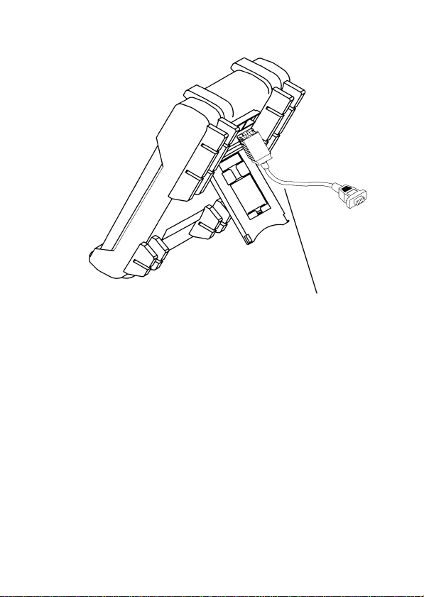
3.8 RS-232C
本器は RS-232C インタフェースを利用したデータの送信機
能を装備しています。この機能によって、パソコンと接続し
てデータの転送を行い、パソコンで記録、および保存するこ
とができます。この機能を利用するには、専用の通信ケーブ
ルとソフトウェアがセットになった別売のオプション(3854
RS-232C パッケージ)が必要です。
パソコンにデータ転送を行う場合には次の手順に従ってくだ
さい。
(1) ホルスタにコネクタを接続します。このときコネクタに
貼付されたラベルが下になるように接続してください。
(2) 9 ピンのコネクタをパソコンの COM1 または COM2 に
接続します。
(3)
RANGE
RS232
(4) 3854 RS-232C パッケージのソフトウェアを実行しデー
タを取り込んでください。
注記 ソフトウェアの使用方法は「3584 RS-232C パッケージ」
データ通信機能
キーを押しながら電源を投入します。表示に
が点灯します。
に付属の取扱説明書を参照してください。
RS-232C 通信機能は電源を OFF にするまで有効です。
―――――――――――――――――――――――
3.8 RS-232C
データ通信機能
Page 41
――――――――――――――――――――――――――
。
ラベルを下にして接続します
37
―――――――――――――――――――――――
3.8 RS-232C
データ通信機能
Page 42

38
――――――――――――――――――――――――――
―――――――――――――――――――――――
3.8 RS-232C
データ通信機能
Page 43

――――――――――――――――――――――――――
、
39
第4章 仕様
一般仕様
4.1
測定方式 二重積分方式
交流測定方式 平均値測定方式
測定機能 直流電圧(DCV)、交流電圧(ACV)、抵抗
(Ω)、直流電流(DCA)、交流電流(ACA)
導通チェック、ダイオードテスト、容量
(C)
付加機能 オートレンジ機能
レコーディング(MAX/MIN/AVG)機能
データホールド
リフレッシュホールド
4-20mA/%表示
相対値表示機能(REL 機能)
オートパワーセーブ機能
電池寿命警告機能
RS-232C インタフェース
表示方式 液晶表示体
表示 □データ表示部
最大 9999/3999 カウント
極性表示
オーバーレンジ表示
□バーグラフ表示部
スケール表示 41 ドットバーグラフ表示
極性表示 正入力時
レンジ切換え フルオートレンジ/マニュアルレンジ
"‑"
マークのみ自動点灯
"OL"
"+"
"‑OL"
または
負入力時
―――――――――――――――――――――――
を表示
"‑"
マークを点灯
4.1
一般仕様
Page 44

40
――――――――――――――――――――――――――
サンプルレート
入力構成
電源 積層形乾電池(6F22)×1 個(9V)
電池寿命警告 約 6.3〜7.5 V 以下で電池消耗表示が点滅
寸法 約 76W×167H×33D m m
質量 約 300 g(本体、電池)
耐電圧 AC 6 kV rm s sin(50/60 Hz 1 分間)
電気的性能 測定確度:確度表による(4.2 参照)
温度特性 測定確度×0.15/℃
ノイズ排除 NMRR DCV -60 dB 以上 (50/60 Hz)
定格電源電圧 DC9.0V×1(積層形乾電池 6F22×1 )
定格電力 35 mVA(Typ.)
(DCV 電源電圧=9.0 V )
(ダイオード(RS232-C 使用)電源電圧=9.0 V )
連続動作時間 約100 時間(DCV、使用乾電池:積層形乾電
3 回 / 秒
V, Ω,C,導通, ダイオード端子
μA, mA, 4-20mA 端子
A 端子
COM 端子
の 4 端子構成
約 400 g(本体、ホルスタ、電池)
確度保証:23℃±5℃
80% r h 以下(結露のないこと)
電源電圧:9V〜電池消耗表示点滅まで
(0℃〜18℃、または 28℃〜40℃)
CMRR DCV -120 dB 以上 (50/60 Hz)
ACV -60 dB 以上 (50/60 Hz)
(1kΩ Unbalance)
50 mVA(Max.)
池(マンガン))
―――――――――――――――――――――――
一般仕様
4.1
Page 45

――――――――――――――――――――――――――
)
、
使用温湿度範囲
保存温湿度範囲
使用場所 屋内、高度 2000 m まで
付属品
オプション 3851-10 テストリード
保護用
ヒューズ
適合規格 安全性
EMC
μA・mA 用
0.5 A/660 V、φ6.35-32 mm、遮断容量 30 kA
または 70125(SIBA 社製)
0.5 A/700 V、φ6.35-32 mm、遮断容量 50 kA
A 用
0〜40℃ 80% rh 以下(結露のないこと
-20〜60℃ 80% rh 以下
(乾電池未装着時、結露のないこと)
3851-10 テストリード、ホルスタ、取扱説明書
電池(積層形乾電池(6F22)×1 本体内蔵 )
ホルスタ
3853 携帯用ケース
3854 RS-232C パッケージ
9617 台付クリップ
9618 クリップ形リード
D086483P(FERRAZ 社製)
TDC600(バスマン社製)
10 A/600 V、φ6.35-25.35 mm、遮断容量 10 kA
EN 61010-1:2001
EN 61010-2-031:1994
汚染度 2 測定カテゴリⅡ(1000 V)測
定カテゴリⅢ(600 V)
(予想される過渡過電圧 6000 V)
UL 3111-1:1994
CAN/CSA-C22.2 No.1010-1-92+B-97
CAN/CSA-C22.2 No.1010.2.031-94
EN61326:1997+A1:1998+A2:2001
+A3:2003
41
―――――――――――――――――――――――
一般仕様
4.1
Page 46

42
――――――――――――――――――――――――――
確度表
4.2
確度保証条件
・23℃±5℃、80%rh 以下 ただし結露なきこと
確度保証期間
・確度保証条件にて 1 年間保証
(1) DCV ファンクション
レンジ 分解能 測定確度 過負荷保護
999.9 mV 0.1 mV ±0.3%rdg.±5dgt.
9.999 V 1mV
99.99 V 10 mV
999.9 V 0.1 V ±0.5%rdg.±5dgt.
・入力インピーダンス:10 MΩ (999.9 mVレンジ:15 MΩ)
±0.3%rdg.±2dgt.
DC1000 V/
AC1000 Vrms
または10
6
V・Hz
(2) ACV ファンクション
①
40 Hz〜200 Hz
レンジ 分解能 測定確度 過負荷保護
999.9 mV 0.1 mV ±2.5%rdg.±5dgt.
9.999 V 1mV
999.9 V 0.1 V
②
200 Hz〜500 Hz
レンジ 分解能 測定確度 過負荷保護
999.9 mV 0.1 mV −
9.999 V 1mV
999.9 V 0.1 V
・5.0 mV以下の入力の場合、測定確度は表中の数値に20 dgt 加算
・入力インピーダンス:10 MΩ (999.9 mVレンジ:15 MΩ)
±1.2%rdg.±5dgt.99.99 V 10 mV
±1.5%rdg.±5dgt.99.99 V 10 mV
DC1000 V/
AC1000 Vrms
または10
DC1000 V/
AC1000 Vrms
または10
6
6
V・Hz
V・Hz
―――――――――――――――――――――――
確度表
4.2
Page 47

――――――――――――――――――――――――――
43
(3) DCA ファンクション
レンジ 分解能 測定確度 内部抵抗 過負荷保護
400.0μA 0.1μA ±0.3%rdg.±3dgt. 約100Ω
4000μA 1μA ±0.2%rdg.±3dgt. 約100Ω
40.00 mA 10μA ±0.3%rdg.±3dgt. 約1Ω
400.0 mA 0.1 mA ±0.2%rdg.±3dgt. 約1Ω
4.000 A 1mA ±0.4%rdg.±3dgt. 約0.01Ω 10 A/600 V
10.00 A 10 mA ±0.5%rdg.±3dgt. 約0.01Ω
・10 Aレンジの測定時間:連続入力(10 A),30秒(20 A以下.5分間以上
の間隔をあける事)
0.5 A/600 V
Quick
Acting Fuse
Quick
Acting Fuse
(4) ACA ファンクション
レンジ 分解能 測定確度 内部抵抗 過負荷保護
400.0μA 0.1μA
4000μA 1μA 約100Ω
40.00 mA 10μA 約1Ω
400.0 mA 0.1 mA 約1Ω
4.000 A 1mA 約0.01Ω 10 A/600 V
10.00 A 10 mA 約0.01Ω
・10 Aレンジの測定時間:連続入力(10 A),15秒(20 A以下、5分間以
上の間隔をあける事)
±1.2%rdg.±5dgt.
(40 Hz〜500 Hz)
±1.8%rdg.±5dgt.
(500 Hz〜2 kHz)
約100Ω
0.5 A/600 V
Quick
Acting Fuse
Quick
Acting Fuse
(5) Ωファンクション
レンジ 分解能 測定確度
400.0 Ω 0.1 Ω
4.000 kΩ 1Ω
40.00 kΩ 10 Ω
400.0 kΩ 100 Ω
4.000 MΩ 1kΩ ±1%rdg.±3dgt.
40.00 MΩ 10 kΩ ±2%rdg.±3dgt.
±0.6%rdg.±3dgt.
開放端子
電圧
3.3 V
max.
1.28 V
max.
過負荷保護
DC600 V/
AC600 Vrms
―――――――――――――――――――――――
確度表
4.2
Page 48

44
――――――――――――――――――――――――――
(6) 導通チェックファンクション
レンジ しきい値 過負荷保護
導通
・導通チェックファンクションにおいてはリラティブモードを使用
し、残留値を0にします。
・測定確度、開放端子電圧はΩファンクションによります。
各レンジの100カウント以下の場合に内
蔵ブザーが鳴動
DC600 V/
AC600 Vrms
(7) C ファンクション
レンジ 分解能 測定確度 過負荷保護
4.000μF 1nF
40.00μF 0.01μF
400.0μF 0.1μF ±3.5%rdg.±4dgt.
9999μF 1μF
・フィルムコンデンサまたは同等のリークの少ないコンデンサを使用
し、リラティブモードで残留値を0にします。
±2.0%rdg.±4dgt.
±3.5%rdg.±5dgt.
2 mF以上では規定せず
DC600 V/
AC600 Vrms
(8) ダイオードファンクション
レンジ 分解能 測定確度
ダイオード 1mV±1.0%rdg.±2dgt. 約0.7 mA
・導通チェック機能動作時には測定電圧が約100 mV以下の場合に内蔵
ブザーが鳴ります。
測定電流測定電圧過負荷
3.3 V
以下
保護
DC600 V/
AC600
Vrms
―――――――――――――――――――――――
確度表
4.2
Page 49

――――――――――――――――――――――――――
45
第5章 保守・サービス
電池およびヒューズの交換方法
5.1
・感電事故を避けるため、テストリードを被測定
物より外してからケースを開け、電池、ヒューズ
を交換してください。また、交換後は必ず ケー
スをしてから、ねじ止め後使用してください。
・電池交換するときは極性+−に注意し、逆挿入
しないでください。性能劣化や液漏れの原因と
なります。また、必ず指定の電池と交換してくだ
さい。
・使用済の電池をショート、分解、火中への投入は
しないでください。破裂する恐れがあり、危険で
す。使用済の電池は、地域で定められた規則に従
って処分してください。
・ヒューズ交換は、指定された形状と特性、定格電
警告
流、電圧のものを使用してください。指定以外の
ヒューズを用いたりヒューズホルダを短絡し て
使用すると、人身事故になるので注意してくだ
さい。
μAmA端子用:
D086483P(FERRAZ 社製)
0.5 A/660 V、φ6.35-32 mm、遮断容量 30 kA
または 70125(SIBA 社製)
0.5 A/700 V、φ6.35-32 mm、遮断容量 50 kA
A端子用:
TDC600(バスマン社製)
10 A/600 V、φ6.35-25.35 mm、遮断容量 10 kA
―――――――――――――――――――――――
電池およびヒューズの交換方法
5.1
Page 50

46
A 端子用
μAmA端子用
積層形乾電池(
)
――――――――――――――――――――――――――
図を参照し、以下の手順で交換してください。
(1) テストリードを測定回路から外し、ファンクションスイ
ッチが OFF になっていることを確認します。
(2) ホルスタを外します。
(3) 下ケースを(本体底面)を上にし、プラスドライバーを
使用してケース留めネジを 3 本外します。
(4) 下ケースを持ち上げて外します。
積層形乾電池(6F22)×1 を交換します。
(5) 断線ヒューズを交換します。ヒューズは、μAmA端子
用と A 端子用がありますので、間違えないようにしてく
ださい。
(6) 下ケースを元に戻しネジ留めします。
6F22
―――――――――――――――――――――――
電池およびヒューズの交換方法
5.1
Page 51

――――――――――――――――――――――――――
本器のクリーニング
5.2
本器の外装の汚れをとるときは、柔らかい布に水または中性
洗剤を少量含ませ軽く拭いてください。ベンジン、アルコー
ル、アセトン、エーテル、シンナー、ガソリン、ラッカー、
ケトン系を含む洗剤は絶対に使用しないでください。変形、
変色することがあります。
サービス
5.3
故障と思われるときは、電池の消耗、ヒューズ、テストリー
ドの断線を確認してから、お買上店か最寄りの営業所に送っ
てください。修理に出される場合は、輸送中に破損しないよ
うに梱包し、故障内容も書き添えてください。輸送中の破損
については保証しかねます。
47
―――――――――――――――――――――――
サービス
5.3
Page 52

48
――――――――――――――――――――――――――
―――――――――――――――――――――――
サービス
5.3
Page 53

保 証 書
形名
3804
本製品は、弊社の厳密なる検査を経て合格した製品をお届けした物です。
万一ご使用中に故障が発生した場合は、お買い求め先にご連絡ください。
本書の記載内容で無償修理をさせていただきます。また、製品の使用による損失について
は、購入金額までの支払いとさせていただきます。なお、保証期間は購入日より3年間で
す。購入日が不明の場合は、製品の製造月から3年を目安とします。ご連絡の際は、本書
を提示してください。また、確度については、明示された確度保証期間によります。
お客様
ご住所: 〒
ご芳名:
*お客様へのお願い
・保証書の再発行はいたしませんので、大切に保管してください。
・「形名、製造番号、購入日」およびお客様「ご住所、ご芳名」は恐れ入りますが、お
客様にて記入していただきますようお願いいたします。
1.取扱説明書・本体注意ラベル(刻印を含む)などの注意事項にしたがった正常な使用
状態で保証期間内に故障した場合には、無償修理いたします。また、製造後一定期間
を経過したものおよび部品の生産中止、不測の事態の発生などにより修理不可能と
なった場合は、修理、校正などを辞退する場合がございます
2.保証期間内でも、次の場合には保証の対象外とさせていただきます。
−1.製品を使用した結果生じる被測定物の、二次的、三次的な損傷、被害
−2.製品の測定結果がもたらす二次的、三次的な損傷、被害
−3.取扱説明書に基づかない不適当な取り扱い、または使用による故障
−4.弊社以外による不当な修理や改造による故障および損傷
−5.取扱説明書に明示されたものを含む、部品の消耗
−6.お買い上げ後の輸送、落下などによる故障および損傷
−7.外観上の変化(筐体のキズなど)
−8.火災、風水害、地震、落雷、電源異常(電圧、周波数など)、戦争・暴動行為、
−9.保証書の提出が無い場合
−10.その他弊社の責任とみなされない故障
−11.特殊な用途(宇宙用機器、航空用機器、原子力用機器、生命に関わる医療用
3.本保証書は日本国内のみ有効です。(This warranty is valid only in Japan.)
サービス記録
年月日 サービス内容
製造番号 保証期間
放射能汚染およびその他天災地変などの不可抗力による故障および損傷
機器及び車輌制御機器など)に組み込んで使用する場合で、前もってその旨
を連絡いただかない場合
購入日 年 月より 3 年間
〒 386-1192 長野県上田市小泉81
TEL 0268-28-0555
FAX 0268-28-0559
06-03
Page 54

外国主要販売ネットワーク
外国代理店については HIOKI ホームページを
ご覧いただくか、最寄りの営業所または本社
販売企画課までお問い合わせください。
URL h ttp: //www. hioki.co. jp/
HIOKI USA CORPORATION
6 Corporate Drive, Cranbury, NJ 08512 USA
TEL +1-609-409-9109
FAX +1-609-409-9108
E-MAIL hioki@hiokiusa.com
Page 55

HIOKI 3804
発行年月 2006 年 9 月 改訂 6 版
編集・発行 日置電機株式会社
開発支援課
問合せ先 日置電機株式会社
販売企画課
〒386-1192 長野県上田市小泉 81
TEL: 0268-28-0560
FAX: 0268-28-0579
E-mail: info@hioki.co.jp
URL htt p: //www.hioki.co.jp/
ディジタルハイテスタ
取扱説明書
0120-72-0560
Pri nted in Jap a n 3804A980-06
・本書の内容に関しては万全を期していますが、ご不明な
点や誤りなどお気づきのことがありましたら、本社 販売
企画課または最寄りの営業所までご連絡ください。
・本書は改善のため予告なしに記載事項を変更すること
があります。
・本書を無断で転載、複製することは禁止されています。
Page 56

Page 57

3804
DIGITAL HiTESTER
INSTRUCTION MANUAL
Page 58

Page 59

Contents
Introduction
Inspection
Safety Notes
Notes on Use
viii
Chapter 1 Overview
1.1 Product Overview 1
1.2 Features
Chapter 2 Names and Functions of Parts 3
2.1 Push Buttons 4
2.2 Rotary Switch
2.3 Input Terminal
2.4 LCD Display Illustration
Chapter 3 Measurement Procedures 11
3.1 Voltage Measurement 13
3.1.1 AC Voltage Measurement 14
3.1.2 DC Voltage Measurement
3.2 Diode Check 16
3.3 Resistance Measurement
3.4 Current Measurement
3.4.1 AC Current Measurement 21
3.4.2 DC Current Measurement
3.5 Capacitance Measurement 23
18
20
i
i
ii
1
2
7
8
9
15
22
Page 60

Chapter 4 Special Functions Instructions 25
4.1 Data Hold 26
4.2 Refresh Hold
4.3 Dynamic Recording
4.4 Relative (Zero)
4.5 % of mA Measurement (4-20mA)
4.6 Beeper On/Off
4.7 Set Up
4.7.1 Timer Setting for Auto-power Save 35
4.7.2 Selecting % Display for 4 to 20 mA
4.8 Communication (RS-232C) 37
27
28
31
32
33
34
36
Chapter 5 Specifications 39
5.1 General Specifications 39
5.2 Accuracy Chart
43
Chapter 6 Maintenance and Service 47
6.1 Changing the Battery and Fuses 47
6.2 Cleaning
6.3 Service
50
50
Page 61

_______________________________________________
Introduction
Thank you for purchasing the HIOKI "3804
DIGITAL HiTESTER". To obtain maximum
performance from the product, please read this
manual first, and keep it handy for future reference.
Inspection
When you receive the product, inspect it carefully to
ensure that no damage occurred during shipping. If
damage is evident, or if it fails to operate according
to the specifications, contact your dealer or Hioki
representative.
Accessories
3851-10 TEST LEAD (a pair) 1
Protective holster 1
Instruction Manual 1
6F22 manganese battery 1
(built into this unit, for monitor)
i
____________________________________________
Introduction
Page 62

ii
_______________________________________________
Safety Notes
WARNING
This product is designed to conform to IEC 61010
Safety Standards, and has been thoroughly tested
for safety prior to shipment. However,
mishandling during use could result in injury or
death, as well as damage to the product. Be
certain that you understand the instructions and
precautions in the manual before use. We
disclaim any responsibility for accidents or
injuries not resulting directly from product
defects.
____________________________________________
Safety Notes
Page 63

_______________________________________________
This manual contains information and warnings
essential for safe operation of the product and for
maintaining it in safe operating condition. Before
using the product, be sure to carefully read the
following safety notes.
Safety symbols
The symbol printed on the product
indicates that the user should refer to
a corresponding topic in the manual
(marked with the
symbol) before
using the relevant function.
In the manual, the symbol indicates
particularly important information that
the user should read before using the
product.
Indicates a double-insulated device.
Indicates DC (Direct Current).
Indicates AC (Alternating Current).
Indicates both DC and AC.
Indicates grounding terminal.
Indicates that dangerous voltage may be
present at this terminal.
iii
____________________________________________
Safety Notes
Page 64

iv
_______________________________________________
The following symbols in this manual indicate the
relative importance of cautions and warnings.
Indicates that incorrect operation
DANGER
presents an extreme hazard that could
result in serious injury or death to the
user.
Indicates that incorrect operation
WAR NING
presents a significant hazard that could
result in serious injury or death to the
user.
Indicates that incorrect operation
CAUTION
presents a possibility of injury to the
user or damage to the product.
Advisory items related to performance
NOTE
or correct operation of the product.
____________________________________________
Safety Notes
Page 65

_______________________________________________
We define measurement tolerances in terms of f.s.
(full scale), rdg. (reading) and dgt. (digit) values,
with the following meanings:
f.s. (maximum display value or scale length)
The maximum displayable value or the full length of
the scale. This is usually the maximum value of the
currently selected range.
rdg. (reading or displayed value)
The value currently being measured and indicated
on the measuring product.
dgt. (resolution)
The smallest displayable unit on a digital measuring
product, i.e., the input value that causes the digital
display to show a "1".
v
____________________________________________
Safety Notes
Page 66

vi
_______________________________________________
Measurement categories (Overvoltage
categories)
This product conforms to the safety requirements for
CAT II (1000V), CATIII (600V) measurement
products.
To ensure safe operation of measurement product,
IEC 61010 establishes safety standards for various
electrical environments, categorized as CAT I to
CAT IV, and called measurement categories. These
are defined as follows.
CAT I : Secondary electrical circuits connected to
an AC electrical outlet through a
transformer or similar device.
CAT II : Primary electrical circuits in equipment
connected to an AC electrical outlet by a
power cord (portable tools, household
appliances, etc.)
CAT III : Primary electrical circuits of heavy
equipment (fixed installations) connected
directly to the distribution panel, and
feeders from the distribution panel to
outlets.
CAT IV : The circuit from the service drop to the
service entrance, and to the power meter
and primary overcurrent protection device
(distribution panel).
____________________________________________
Safety Notes
Page 67

_______________________________________________
Higher-numbered categories correspond to electrical
environments with greater momentary energy. So a
measurement device designed for CAT III
environments can endure greater momentary energy
thanadevicedesignedforCATII.
Using a measurement product in an environment
designated with a higher-numbered category than
that for which the product is rated could result in a
severe accident, and must be carefully avoided.
Never use a CAT I measuring product in CAT II,
III, or IV environments.
The measurement categories comply with the
Overvoltage Categories of the IEC60664 Standards.
vii
____________________________________________
Safety Notes
Page 68

viii
_______________________________________________
Notes on Use
Follow these precautions to ensure safe operation
and to obtain the full benefits of the various
functions.
Preliminary Check
Before using the product the first time, verify that it
operates normally to ensure that the no damage
occurred during storage or shipping. If you find any
damage, contact your dealer or Hioki representative.
WARNING
Do not use the product where it may be
exposed to corrosive or combustible gases.
The product may be damaged or cause an
explosion.
Before using the product, make sure that the
insulation on the test leads is undamaged and
that no bare conductors are improperly
exposed. Using the product under such
conditions could result in electrocution.
Replace the test leads with the specified Hioki
Model 3851-10.
____________________________________________
Notes on Use
Page 69

_______________________________________________
CAUTION
To avoid damage to the product, do not allow the
product to get wet, and do not use it when your
hands are wet.
Adjustments and repairs should be made only by
technically qualified personnel.
This product should be installed and operated indoors
only, between 0 and 40
However, it can be safely operated down to -10
and 80% RH or less.
.
Do not store or use the product where it could be
exposed to direct sunlight, high temperature or
humidity, or condensation. Under such conditions, the
product may be damaged and insulation may
deteriorate so that it no longer meets specifications.
This product is not designed to be entirely water- or
dust-proof. To avoid damage, do not use it in a wet or
dusty environment.
Do not use the product near a device that generates
a strong electromagnetic field or electrostatic charge,
as these may cause erroneous measurements.
To avoid damage to the product, protect it from
vibration or shock during transport and handling, and
be especially careful to avoid dropping.
If the protective functions of the product are
damaged, either remove it from service or mark it
clearly so that others do not use it inadvertently.
ix
____________________________________________
Notes on Use
Page 70

x
_______________________________________________
NOTE
To avoid corrosion from battery leakage, remove the
batteries from the product if it is to be stored for a
long time.
____________________________________________
Notes on Use
Page 71

_______________________________________________
Chapter 1
Overview
1.1 Product Overview
This multimeter has DCV, ACV, DCA, ACA,
OHM, Diode check, Audible continuity, Capacitor
and % of 4-20 mA tests.
The built-in optical RS-232C will assist you to
capture the data without hazardous as the high
voltage has been measured.
1
____________________________________________
Chapter 1 Overview
Page 72

2
_______________________________________________
1.2 Features
The multimeter is shown in the following Figure.
This meter has a lot of functions can be used in
HVAC, Power, Process fields, Electronic/Electrical
system diagnostics and troubleshooting. It will be
the best one of your need. See below detail:
Resolution of display: 9,999 counts for Voltage
and 3,999 counts for other measurements.
% of mA display can be selected for 4-20 mA or
0-20 mA.
The timer of auto power save can be adjusted
from 1 to 99 minutes even disable this function.
Dynamic Recording helps to record the variation
of tests.
Data Hold to freeze displayed digital value.
Refresh Hold to freeze the digital value for
difficult measuring place.
Relative function
Auto and Manual Ranging
Communication with RS-232C
____________________________________________
Chapter 1 Overview
Page 73

_______________________________________________
Chapter 2
Names and
Functions of Parts
3
____________________________________________
Chapter 2 Names and Functions of Parts
Page 74

4
_______________________________________________
2.1 Push Buttons
The operation of push-button is shown as below.
When push the button, a display symbol will light,
and the beeper will sound. Turning the rotary switch
to another switch setting resets all push buttons to
their default state.
button
SHIFT
For voltage and current measurements, press this
button momentarily to cycle through DC and AC
tests.
For mA measurement, press this button for more
than 1 second to set % of 4-20mA display.
For Ohm test, press button momentarily to toggle
"Audible continuity mode" ON/OFF. Pushing this
button for more than 1 second will exit the
continuity function and returns to the autoranging ohm measurement.
____________________________________________
Chapter 2 Names and Functions of Parts
Page 75

_______________________________________________
button (Data Hold or Refresh Hold)
HOLD
Press this button momentarily to toggle data hold
on or off. The display shows
HOLD
to indicate
the hold function.
The data hold function allows operator to hold the
displayed digital value, if you select " Refresh
Hold " by Power-ON Options, the reading is
updated to the display automatically when the
reading changes. The beeper sounds a tone to
remind user, that an update has occurred.
button (Dynamic Recording)
REC
Records maximum, minimum, and calculates true
average. Press this button for more than 1 second
to toggle recording mode on or off.
Press this button momentarily to cycle through
MAX, MIN, MAX-MIN, AVG and present (
REC
) readings.
The beeper sounds when a new maximum or
minimum value is recorded.
5
____________________________________________
Chapter 2 Names and Functions of Parts
Page 76

6
_______________________________________________
button
REL
Press this button momentarily to toggle the relative
mode ON or OFF.
RANGE
button
In auto-range press this button momentarily to
select manual range and turn off the "AUTO"
annunciator.
In manual range, press this button momentarily to
step up 1 range at one time, press this button for
more than 1 second to select auto-range.
In auto-range, the "AUTO" annunciator is lit and
the meter will select an appropriate range for
measurement being made. If a reading is greater
than maximum available range, "OL"(overload) is
displayed on the screen. The meter selects a lower
range when reading is less than about 9% of full
scale.
____________________________________________
Chapter 2 Names and Functions of Parts
Page 77

_______________________________________________
2.2 Rotary Switch
To select function, turn the rotary switch to a switch
setting. Then the meter is ready for use. (If you
press and hold any push button while pushing the
meter from OFF to ON, the display will remain lit
until the push button is released.)
Power off position.
AC or DC voltage measurements. Initial test
is defined to AC.
Diode Check
Ohm and Continuity measurements
Capacitance measurement.
AC or DC Current measurements
AC or DC Current measurements.
A
AC or DC Current measurements.
7
____________________________________________
Chapter 2 Names and Functions of Parts
Page 78

8
_______________________________________________
2.3 Input Terminal
1
2
1. Volts, Ohms, Diode, Capacitance measurements.
2. Common terminal for all measurements.
3. Current (maximum 400 mA) measurements.
4. Current (maximum 10 A continuous)
measurements.
3
4
____________________________________________
Chapter 2 Names and Functions of Parts
Page 79

_______________________________________________
A
µ
A
µ
2.4 LCD Display Illustration
9
APS
UTO
HOLD
RS232C
REL
Enable Auto power save
Indicates AUTO range Mode
Data hold annunciator
Enable RS-232C
Relative mode annunciator
Direct Current or Voltage
Alternating Current or Voltage
REC
MAX-MIN
MAX
AVG
Dynamic recording mode, Present reading
Different reading for MAX-MIN
Maximum reading
Minimum reading
MIN
Average reading
Diode measurement
Continuity function annunciator
Low battery indicator
% display for 4-20mA measurement
%
mV
m
mF
Units of Voltage measurement
Units of Current measurement
Units of Capacitance measurement
____________________________________________
Chapter 2 Names and Functions of Parts
Page 80

10
_______________________________________________
Mk Ω
Units of Resistance (ohm) measurement
Bar-graph indicator
____________________________________________
Chapter 2 Names and Functions of Parts
Page 81

_______________________________________________
11
Chapter 3
Measurement
Procedures
DANGER
Observe the following precautions to avoid
electric shock.
Always verify the appropriate setting of the
function selector before connecting the test
leads.
Disconnect the test leads from the
measurement object before switching the
function selector.
NOTE
When measuring voltage which includes harmonic
waves
(ex. horizontal output of TV), there is the possibility
that a setting error may occur
____________________________________________
Chapter 3 Measurement Procedures
Page 82

12
_______________________________________________
Preparation for Measurement
The safety caps are attached to the test leads.
Remove these caps before connecting to the unit.
____________________________________________
Chapter 3 Measurement Procedures
Page 83

_______________________________________________
13
3.1 Voltage Measurement
DANGER
The maximum input voltage is 1000 VDC, 1000
Vrms or 10
6
V Hz. Attempting to measure
voltage in excess of the maximum input could
destroy the product and result in personal
injury or death.
To avoid electrical shock, be careful to avoid
shorting live lines with the test leads.
For safety, test lead connections must always
be made at the secondary side of a circuit
breaker.
____________________________________________
Chapter 3 Measurement Procedures
Page 84

14
_______________________________________________
3.1.1 AC Voltage Measurement
(1) Set the rotary switch to "
(2) Connect the black test lead to "COM" terminal
and red test lead to " " terminal.
(3) Touch the test leads to the test points and read
the display.
/ V ".
____________________________________________
Chapter 3 Measurement Procedures
Page 85

_______________________________________________
15
3.1.2 DC Voltage Measurement
(1) Set the rotary switch to "
(2) Push
button momentarily to set DC test.
SHIFT
/ V ".
(3) Connect the black test lead to "COM" terminal
and red test lead to "
" terminal.
(4) Touch the test leads to the test points and read
the display.
____________________________________________
Chapter 3 Measurement Procedures
Page 86

16
_______________________________________________
3.2 Diode Check
DANGER
Never apply voltage to the test leads when the
Diode Check functions is selected. Doing so
may damage the product and result in personal
injury.
To avoid electrical accidents, remove power
from the circuit before measuring.
A good diode allows current to flow in one direction
only. To test a diode, turn the power off, remove the
diode from the circuit, and proceed as follows:
(1) Set the rotary switch to "
" position.
(2) Connect the black test lead to "COM" terminal
and red test lead to "
" terminal.
(3) Touch the test leads to diode and read the
display.
(4) Touch the red lead to the positive side of the
diode and the black lead to the negative side.
The meter can display diode voltage drops to
approximately 2.5 V.
A typical voltage drop is 0.3 to 0.8 V, and the
meter will sound a beep to remind user.
____________________________________________
Chapter 3 Measurement Procedures
Page 87

_______________________________________________
17
Reverse the test leads and measure the voltage
across the diode again. If the diode is:
Good : "OL" is displayed.
Shorted : Near 0 V drop is displayed in both
directions, and the beeper sounds
continuously.
Open : "OL" is displayed in both directions.
Repeat step (3) and (4) for other diodes.
____________________________________________
Chapter 3 Measurement Procedures
Page 88

18
_______________________________________________
3.3 Resistance Measurement
DANGER
Never apply voltage to the test leads when the
Resistance, Continuity Check functions are
selected. Doing so may damage the product
and result in personal injury.
To avoid electrical accidents, remove power
from the circuit before measuring.
(1) Set the rotary switch to " ".
(2) Connect the black test lead to "COM" terminal
and red test lead to "
(3) Touch the test leads to resistor and read the
display.
(4) Press
button momentarily to toggle
SHIFT
CONTINUITY function ON/OFF. The continuity
range is 0 to 400.0 Ω.
(5) Momentarily pushing this button will only turn
the beeper off. While testing continuity, the
beeper will sound if the resistance falls below
100 counts.
" terminal.
____________________________________________
Chapter 3 Measurement Procedures
Page 89

_______________________________________________
19
____________________________________________
Chapter 3 Measurement Procedures
Page 90

20
_______________________________________________
3.4 Current Measurement
DANGER
Never apply voltage to the test leads when a
current measurement function is selected.
Doing so may damage the product and result in
personal injury.
To avoid electrical accidents, remove power
from the circuit before connecting the test
leads.
WARNING
To prevent electrical accidents, do not use the
tester to measure current when the electric
potential is 600 V or greater. The current
function overload protection trips at either 600
V DC, 600 V rms.
____________________________________________
Chapter 3 Measurement Procedures
Page 91

_______________________________________________
21
3.4.1 AC Current Measurement
NOTE
(1) Set the rotary switch to "
/ A ".
(2) Connect the black test lead to "COM" terminal
and red test lead to "A" terminal.
(3) Touch the test leads to the test points and read
the display.
If the reading is lower than 400 mA, to get better
resolution of display, please turn the rotary switch to
mA or µ
A position and remove the red test lead to
"µAmA" terminal.
Instrument operated by
alternatingcurrent
____________________________________________
Chapter 3 Measurement Procedures
Page 92

22
_______________________________________________
3.4.2 DC Current Measurement
NOTE
(1) Set the rotary switch to "
(2) Push
button momentarily to set DC test.
SHIFT
/ A ".
(3) Connect the black test lead to "COM" terminal
and red test lead to "A" terminal.
(4) Touch the test leads to the test points and read
the display.
If the reading is lower than 400 mA, to get better
resolution of display, please turn the rotary switch to
mA or µA position and remove the red test lead to
"µ
AmA" terminal.
____________________________________________
Chapter 3 Measurement Procedures
Page 93

_______________________________________________
23
3.5 Capacitance Measurement
DANGER
Never apply voltage to the test leads when the
Capacitance functions are selected. Doing so
may damage the product and result in personal
injury.
To avoid electrical accidents, remove power
from the circuit before measuring.
(1) Set the rotary switch to " " position
(2) Connect the red lead to "
lead in "COM" terminal.
(3) Open test leads, then push
momentarily to zero the residual.
(4) Remove the capacitor from circuit board or
device.
(5) Connect the test lead across the capacitor and
read the display.
" terminal, and black
button
REL
____________________________________________
Chapter 3 Measurement Procedures
Page 94

24
_______________________________________________
NOTE
Observe polarity when measuring the polarized
capacitors.
Discharge capacitor before measurement.
When testing low-capacitance devices, noise
introduced into the test leads from the human
body may prevent the measured value from
stabilizing. If this occurs, use the optional 9617
CLIP ON BASE or the optional 9618 CLIP-TYPE
LEAD and keep hands away from the leads
during measurement.
____________________________________________
Chapter 3 Measurement Procedures
Page 95

_______________________________________________
25
Chapter 4
Special Functions
Instructions
This multi-meter provides the operator with various
functions including:
(1) Data Hold
(2) Refresh Hold
(3) Dynamic Recording
(4) Relative (Zero)
(5) % of mA Measurement (4-20 mA)
(6) Beeper On/Off
(7) Set Up
(8) Communication (RS-232C)
____________________________________________
Chapter 4 Special Functions Instructions
Page 96

26
_______________________________________________
4.1 Data Hold
The data hold function allows operators to hold the
displayed digital value, while the analog bar graph
continues showing the present readings. Press
button to enter the data hold mode, and the "
will be displayed. Press the button again to exit. The
present reading is now shown.
HOLD
HOLD
"
NOTE
The range is held in the case of auto range.
____________________________________________
Chapter 4 Special Functions Instructions
Page 97

_______________________________________________
27
4.2 Refresh Hold
The reading is updated the value automatically and
the beeper sounds when the measurement value
changes 30 counts at least.
The refresh hold mode is effective until the power
supply is turned off.
(1) To active the refresh hold mode, turn on the
power supply while pressing the
(2) Release the button after all the LCD segments
are lit. Press any button for the measurement
modes
(3) Press
button to select ON/OFF of the
HOLD
refresh hold. While the refresh hold mode is
effective ,
HOLD
is displayed.
HOLD
button.
NOTE
When the reading value is unstable, the 3804 may
not update the display.
In the voltage, current, and capacitance function,
the reading is not updated when the measurement
value is less than 50 counts.
In the resistance and diode function, the reading
is not updated when the reading is "OL" or the
test leads are open.
The hold mode and the refresh hold mode use the
same display, so please pay attention when
measuring to make sure you are in the correct
mode.
____________________________________________
Chapter 4 Special Functions Instructions
Page 98

28
_______________________________________________
4.3 Dynamic Recording
The dynamic recording mode can be used to catch
intermittent and turn on or turn off surges, verify
performance, measure while you are away, or take
readings while you are operating the equipment
under test and can not watch the meter.
The average reading is useful for smoothing out
unstable or changing inputs, estimating the percent
of time a circuit is operational, or verifying circuit
performance.
The operational procedures are described below:
(1) Press
enter the dynamic recording. The present value
is stored to memories of maximum, minimum
and average, and the annunciator turns on.
(2) Press
toggle recording mode on or off.
(3) Press
maximum, minimum, maximum - minimum,
average and present readings. The MAX, MIN,
MAX-MIN, AVG or annunciator will turn on
respectively to indicate what value is being
displayed.
button for more than 1 second to
REC
button for more than 1 second to
REC
button momentarily to cycle through
REC
____________________________________________
Chapter 4 Special Functions Instructions
Page 99

_______________________________________________
29
(4) The beeper sounds when a new maximum or
minimum value is recorded.
(5) If an overload is recorded the averaging function
is stopped. An average value becomes
"OL"(overload).
NOTE
In dynamic recording, the auto power save feature
is disabled, after disabled and the "
APS
" turns
off.
Select dynamic recording in auto range, it will
record the values of MAX, MIN or AVG for
different ranges.
The record speed of dynamic recording is about
100 ms (0.1 s).
The average value is the true average of all
measured values taken since the recording mode
was entered.
If the range is changed in the manual range mode
or the function is changed, the dynamic recording
function is canceled.
____________________________________________
Chapter 4 Special Functions Instructions
Page 100

30
_______________________________________________
Press
more than 1 second
REC
button for
Current value
Maximum value
Minimum value
Max. - Min. value
Average value
____________________________________________
Chapter 4 Special Functions Instructions
 Loading...