

Page 1

取扱説明書
Instruction Manual
3803
ディジタルハイテスタ
DIGITAL HiTESTER
2010年4月 発行 改訂10版
April 2010 Revised edition 10 3803A980-10 10-04H
Page 2

Page 3

――――――――――――――――――――――――――
目次 1
目 次
はじめに 1
点検
安全について
ご使用にあたっての注意
1
2
5
第 1 章 概要
1.1 製品概要
1.2 各部の名称と機能
第 2 章 基本測定
2.1 始業前点検
2.1 交流/直流電圧測定
2.2 ダイオードチェック
2.3 抵抗測定/導通チェック
2.4 交流/直流電流測定
第 3 章 応用機能
3.1 データホールド機能
3.2 オートパワーセーブ機能
3.3 通信機能(オプション)
第 4 章 仕様
4.1 一般仕様
4.2 確度表
第 5 章 保守・サービス
5.1 電池およびヒューズの交換方法
5.2 本器のクリーニング
5.3 サービス
7
7
8
13
14
15
17
19
21
23
24
25
26
29
29
32
35
35
37
37
―――――――――――――――――――――――
Page 4

目次 2
――――――――――――――――――――――――――
―――――――――――――――――――――――
Page 5

――――――――――――――――――――――――――
はじめに
1
このたびは、
いただき、誠にありがとうございます。この製品を十分にご
活用いただき、末長くご使用いただくためにも、取扱説明書
はていねいに扱い、いつもお手元に置いてご使用ください。
HIOKI3803
ディジタルハイテスタをご選定
点検
本器がお手元に届きましたら、輸送中において異常または破
損がないか点検してからご使用ください。万一、破損あるい
は仕様どおり動作しない場合は、お買上店か最寄りの営業所
にご連絡ください。
□ 付属品
3851-10
ホルスタ
取扱説明書
積層形マンガン乾電池(
テストリード(赤黒各1)
1
1
6F22
1
)(本体内蔵、モニタ用)
1
―――――――――――――――――――――――
Page 6

2
――――――――――――――――――――――――――
安全について
この取扱説明書には、本器を安全に操作し、安全な状態を保
つのに要する情報や注意事項が記載されています。本器を使
用する前に、下記の安全に関する事項をよくお読みください。
この機器は IEC 61010 安全規格に従って、設計さ
れ、試験し、安全な状態で出荷されています。測定
方法を間違えると人身事故や機器の故障につなが
る可能性があります。取扱説明書を熟読し、十分に
警告
内容を理解してから操作してください。万一事故
があっても、弊社製品が原因である場合以外は責
任を負いかねます。
安全記号
○
・使用者は、機器上に表示されている マークの
ところについて、取扱説明書の
箇所を参照し、機器の操作をしてください。
・使用者は、取扱説明書内の
ろは、必ず読み、注意する必要があることを示し
ます。
二重絶縁または強化絶縁で保護されている機器を
示します。
直流(DC)を示します。
交流(AC)を示します。
直流(DC)と交流(AC)の両用を示します。
接地端子を示します。
この端子には、危険な電圧がかかることを示しま
す。
マークの該当
マークのあるとこ
―――――――――――――――――――――――
Page 7
――――――――――――――――――――――――――
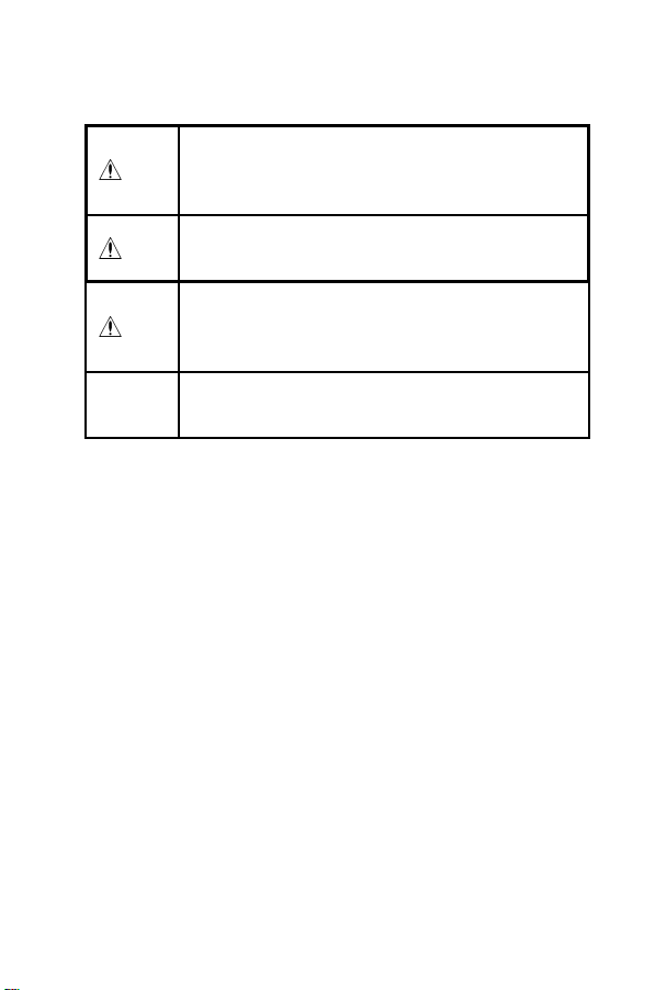
取扱説明書の注意事項には、重要度に応じて以下の表記がさ
れています。
操作や取扱いを誤ると、使用者が死亡または重傷
につながる危険性が極めて高いことを意味しま
危険
す。
操作や取扱いを誤ると、使用者が死亡または重傷
警告
につながる可能性があることを意味します。
操作や取扱いを誤ると、使用者が傷害を負う場合、
または機器を損傷する可能性があることを意味し
注意
ます。
3
注記
■ 確度について
弊社では測定値の限界誤差を、次に示す
rdg.
義しています。
f.s.
最大表示値または、目盛長を表します。一般的には、現在使
用中のレンジを表します。
rdg.
現在測定中の値、測定器が現在指示している値を表します。
dgt.
ディジタル測定器における最小表示単位、つまり最小桁の
を表します。
製品性能および操作上でのアドバイス的なことを
意味します。
f.s.
(フルスケール)、
(リーディング)、
(最大表示値、目盛長)
(読み値、表示値、指示値)
(分解能)
dgt.
(デジット)に対する値として定
"1"
―――――――――――――――――――――――
Page 8
4
――――――――――――――――――――――――――
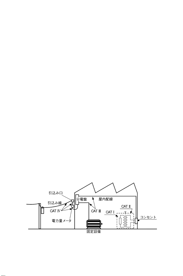
■測定カテゴリ(過電圧カテゴリ)について
CATII(1000V),CATIII(600V
本器は
測定器を安全に使用するため、
として、使用する場所により安全レベルの基準を
CAT
Ⅳで分類しています。概要は下記のようになります。
CAT
Ⅰ:コンセントからトランスなどを経由した機器内の
二次側の電気回路
CAT
Ⅱ:コンセントに接続する電源コード付き機器(可搬形
工具・家庭用電気製品など)の一次側電路
CAT
Ⅲ:直接分電盤から電気を取り込む機器(固定設備)の
一次側および分電盤からコンセントまでの電路
CAT
Ⅳ:建造物への引込み電路、引込み口から電力量メータ
および一次側電流保護装置(分電盤)までの電路
数値の大きいカテゴリは、より高い瞬時的なエネルギーのあ
る電気環境を示します。そのため、
CAT
器は、
に耐えることができます。
カテゴリの数値の小さいクラスの測定器で、数値の大きいク
ラスに該当する場所を測定すると重大な事故につながる恐れ
がありますので、絶対に避けてください。
特に、
の測定に用いないでください。
測定カテゴリは
Ⅱで設計されたものより高い瞬時的なエネルギー
CAT
Ⅰの測定器を
IEC60664
IEC61010
CAT
Ⅱ、ⅢおよびⅣに該当する場所
の過電圧カテゴリに対応します。
)に適合しています
では測定カテゴリ
CAT
Ⅲで設計された測定
CAT
Ⅰ〜
―――――――――――――――――――――――
Page 9

――――――――――――――――――――――――――
ご使用にあたっての注意
本器を安全にご使用いただくために、また機能を十二分に活
用いただくために、下記の注意事項をお守りください。
使用前の点検
使用前には、保存や輸送による故障がないか、点検と動作確
認をしてから使用してください。故障を確認した場合は、お
買上店(代理店)か最寄りの営業所にご連絡ください。
・リード線の被覆が破れたり、金属が露出してい
ないか、使用する前に確認してください。損傷が
ある場合は、感電事故になるので、指定の 3851-
警告
注意
10 と交換してください。
・腐食性のガスや爆発性ガスが発生する場所では
使用しないでください。本器の破損、もしくは爆
発事故を誘発する可能性があります。
・本器をぬらしたり、ぬれた手で測定しないでく
ださい。本器の損傷の原因になります。
・本器の調整や修理は、危険を良く知った技能者
の責任で行なってください。
・本器の使用環境および設置場所は、使用温湿度
範囲 0〜40℃、80% rh 以下の屋内ですが、安全
性を損なわないで-10℃までの範囲で使用でき
ます。
5
―――――――――――――――――――――――
Page 10
6
――――――――――――――――――――――――――
・直射日光や高温、多湿、結露するような環境下で
の、保存や使用はしないでください。変形、絶縁
劣化を起こし、仕様を満足しなくなります。
・本器は防水、防じん構造となっていません。ほこ
りの多い環境や水のかかる環境下で使用しな い
でください。故障の原因になります。
・強力な電磁波を発生するもの、または帯電して
注意
注記 電池の液漏れによる腐食を防ぐため、長い間使用しない
いるものの近くで使用しないでください。誤動
作の原因となります。
・本器の損傷を防ぐため、運搬および取扱いの際
は振動、衝撃を避けてください。特に、落下など
による衝撃に注意してください。
・本器の保護機能が破損している場合は、使用で
きないように廃棄するか、知らないで動作させ
ることのないように表示しておいてください。
ときは、電池を抜いて保管してください。
―――――――――――――――――――――――
Page 11

――――――――――――――――――――――――――
第1章 概要
製品概要
1.1
本器は、直流電圧、交流電圧、直流電流、交流電流、抵抗、
ダイオードチェック、導通チェックが可能な多機能ディジタ
ルマルチメータです。
光伝送式の
測定時に便利です。
RS-232C
データ通信では、高電圧測定や昼夜連続
7
―――――――――――――――――――――――
第1章 概要
Page 12

8
⑤
⑩
③
②
⑥
①
⑦
⑨
⑧
④
――――――――――――――――――――――――――
各部の名称と機能
1.2
LCD ディスプレイ
SHIFT キー
HOLD キー
RS-232C キー
RANGE キー
ファンクション
スイッチ
V,Ω端子
COM 端子
μA, mA 端子
A 端子
―――――――――――――――――――――――
第1章 概要
Page 13

――――――――――――――――――――――――――
① SHIFT キー
SHIFT
キーはファンクションにより機能が異なります。
ファンクション 機能
電圧・電流 AC 測定 /DC測定 の切換え
抵抗・導通 抵抗測定と導通チェックの切換え
② HOLD キー
・測定値のホールドの
③ RS-232C キー
RS-232C
・
④ RANGE キー
・オートレンジ(
えます。マニュアルレンジの場合1秒以上押し続けると
オートレンジになります。
・マニュアルレンジの場合、レンジアップします。
オートレンジの場合、表示値が
とレンジアップします。また、表示値が
を下回ると、レンジダウンします。レンジを超えた入力
の場合には、
機能の
ON/OFF
ON/OFF
AUTO
)とマニュアルレンジ(R)を切り換
"OL"(overload
をします(
をします(
3950
)が表示されます。
3.1
参照)。
3.3
参照)。
カウントを超える
350
カウント
9
―――――――――――――――――――――――
第1章 概要
Page 14
10
――――――――――――――――――――――――――
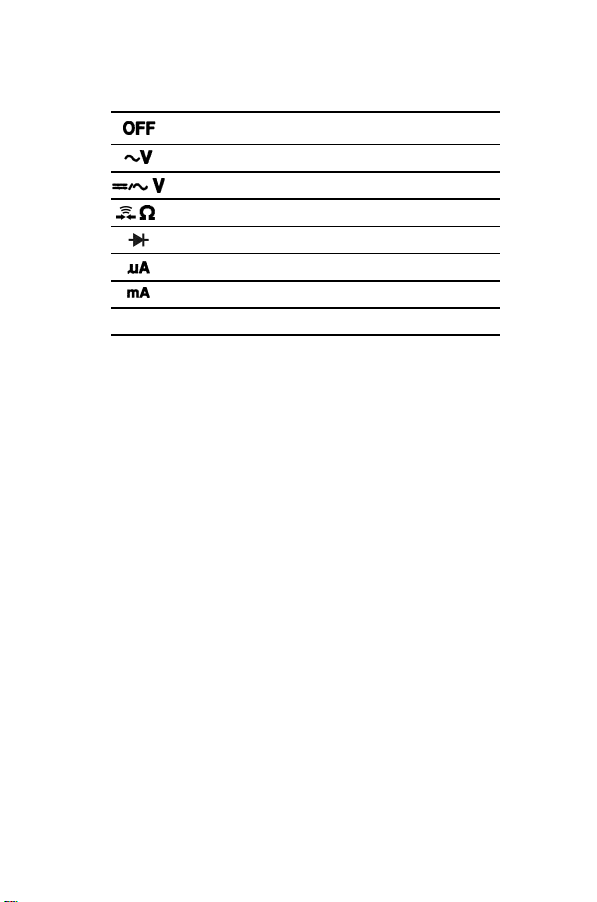
⑤ ファンクション・スイッチ(ファンクション・SW)
ファンクションの選択、電源の
OFF
電源
AC
電圧
DC、AC
抵抗、導通チェック
ダイオードチェック
DC、ACμA
DC、ACmA
DC、AC
A
⑥ V, Ω, 導通, ダイオード端子
電圧、抵抗、ダイオードファンクションのときに使用する
端子です。
⑦ COM 端子
各測定の共通端子です(テストリードの黒を接続します)。
⑧ μA, mA 端子
μA、mA測定のときに使用する端子です。
⑨ A 端子
A
測定のときに使用する端子です。
電圧
電流
電流
電流
ON/OFF
を行います。
―――――――――――――――――――――――
第1章 概要
Page 15
――――――――――――――――――――――――――
μ
A
Ω
11
⑩ LCD ディスプレイ
APS
AUTO
HOLD
RS232C
オートパワーセーブ機能が起動していることを示
します。
オートレンジ機能が起動していることを示します。
R
マニュアルレンジを示します。
データホールド中であることを示します。
RS-232C
DC
AC
が使用可能なことを示します。
(直流)を示します。
(交流)を示します。
ダイオードファンクションを示します。
導通ファンクションを示します。
電池消耗表示を示します。
mV
Mk
電圧単位を示します。
電流単位を示します。
m
抵抗単位を示します。
バーグラフを示します。
―――――――――――――――――――――――
第1章 概要
Page 16

12
――――――――――――――――――――――――――
―――――――――――――――――――――――
第1章 概要
Page 17

――――――――――――――――――――――――――
13
第2章 基本測定
感電事故を防ぐため、下記のことをお守りくださ
い。
・測定前に必ずファンクションスイッチの位置を
危険
注記 トランスや大電流路など強磁界の発生している近く、ま
測定前の準備
テストリードについている保護キャップを外してください。
確認してください。
・ファンクションスイッチを切り換えるとき は、
テストリードを被測定物から外してください。
た無線機など強電界の発生している近くでは、正確な測
定ができない場合があります。
―――――――――――――――――――――――
第2章 基本測定
Page 18

14
――――――――――――――――――――――――――
始業前点検
2.1
電気事故や誤測定を防ぐため、本器を使用する前に下記事項
を確認してください。動作確認をして異常があった場合は、
途中でも点検を中止し、本器を使用しないでください。
本体部分に損傷がないか、またリード線の被覆
が破れたり、金属が露出していないか、使用する
警告
・電圧測定では、テストリードを短絡した状態で表示が0Vに
なること。
・抵抗測定、導通チェックでは、テストリードを短絡した状態
で表示が0Ωとなること。
・あらかじめ値のわかっている試料(電池、商用電源、抵抗器
など)を測定し、所定の値が表示されること。
注記 本器が製品仕様通り動作するかの確認には、定期的な点
前に確認してください。損傷がある場合は、感電
事故の原因になるので、お買上店(代理店)か最
寄りの営業所にご連絡ください。
検・校正が必要です。
―――――――――――――――――――――――
第2章 基本測定
Page 19

――――――――――――――――――――――――――
交流/直流電圧測定
2.2
・最大入力電圧は、DC1000 V、AC1000 Vrms また
6
V・Hz です。この最大入力電圧を超えると
は 10
本器を破損し、人身事故になるので測定しない
でください。
・感電事故を防ぐため、テストリードの先端で電
危険
圧のかかっているラインを短絡しないでくだ さ
い。
・テストリードによる測定箇所は、安全のため必
ずブレーカの二次側で行なってください。
15
(1) ファンクションスイッチを「
にセットします。
「
(2) 黒色のテストリードを COM 端子に、赤色のテストリー
(3) 測定対象回路にテストリードを接続し表示値を読みます。
(4)
注記 無入力時は、誘導電圧により表示値がふらつく場合があ
」では、
直流(
ドを V.
RANGE
りますが、故障ではありません。
)が切り換わります。
端子に接続してください。
キーで測定レンジを切り換えることができます。
キーを押すごとに交流( )/
SHIFT
―――――――――――――――――――――――
」、または「 」
第2章 基本測定
Page 20

16
――――――――――――――――――――――――――
交流電圧測定
直流電圧測定
―――――――――――――――――――――――
第2章 基本測定
Page 21

――――――――――――――――――――――――――
ダイオードチェック
2.3
・ダイオードチェックファンクションに電圧を入
力しないでください。本器を破損し、人身事故に
危険
正常なダイオードは一方向のみ電流が流れます。
なります。
・電気事故を防ぐため、測定回路の電源を切って
から、測定してください。
17
(1) ファンクションスイッチを「
(2) 黒色のテストリードを COM 端子に、赤色のテストリー
ドを"
(3) ダイオードのアノードへ赤色テストリード、カソードへ
黒色テストリードを接続します。
本器は約 1.999 V までダイオードの電圧を測定します。
ダイオードの典型的な電圧は 0.3〜0.8 V です。
テストリードを逆に接続すると次のような表示をします。
正常なダイオード :「OL」
短絡したダイオード :両方向とも約 0V
断線しているダイオード :両方向とも「OL」
"端子に接続してください。
―――――――――――――――――――――――
」にセットしてください。
第2章 基本測定
Page 22

18
――――――――――――――――――――――――――
ダイオードチェック
―――――――――――――――――――――――
第2章 基本測定
Page 23

――――――――――――――――――――――――――
抵抗測定/導通チェック
2.4
・抵抗/導通チェックのファンクションに電圧を
入力しないでください。本器を破損し、人身事故
危険
になります。
・電気事故を防ぐため、測定回路の電源を切って
から、測定してください。
19
(1) ファンクションスイッチを「
さい。
(2) 黒色のテストリードを COM 端子に、赤色のテストリー
ドを
(3) 測定対象回路にテストリードを接続し表示値を読みます。
SHIFT
(4)
が点灯)が切り換わります。このときオートレンジは解
除されます
SHIFT
(5)
解除され抵抗測定(オートレンジ)になります。
ブザーは各レンジの 345 カウント以下の場合に鳴ります。
350 カウント以上になると鳴り止みます。
端子に接続してください。
キーを押すごとに抵抗測定と導通チェック(
キーを 1 秒以上押し続けると導通チェック機能が
―――――――――――――――――――――――
」にセットしてくだ
第2章 基本測定
Page 24

20
――――――――――――――――――――――――――
抵抗測定/導通チェック
―――――――――――――――――――――――
第2章 基本測定
Page 25

――――――――――――――――――――――――――
交流/直流電流測定
2.5
・電流測定のファンクションに電圧を入力しない
でください。本器を破損し、人身事故になりま
危険
警告
(1) ファンクションスイッチを「A」にセットします。
(2)
(3) 黒色のテストリードを COM 端子に、赤色のテストリー
(4) 測定対象回路にテストリードを接続し表示値を読みます。
(5)
注記 読み値が 400 mA よりも低く、かつ、より分解能が必要
す。
・電気事故を防ぐため、測定回路の電源を一度切
ってから、テストリードを接続してください。
・電気事故を防ぐため、600 V 以上の電位の場合、
回路内の電流測定はしないでください。電流フ
ァンクションの過負荷保護は、DC600 V または
AC600 Vrms です。
キーを押すごとに交流( )/直流( )
SHIFT
が切り換わります。
ドを A 端子に接続してください。
キーで測定レンジを切り換えることができます。
RANGE
な場合には、測定対象回路からいったんテストリードを
離し、ファンクションスイッチを「mA」、または「μA」
にセットします。赤色のテストリードはファンクション
に合わせて mA、またはμA 端子に接続してください。
21
―――――――――――――――――――――――
第2章 基本測定
Page 26
22
――――――――――――――――――――――――――
交流駆動機器
交流電流測定
直流電流測定
―――――――――――――――――――――――
第2章 基本測定
Page 27

――――――――――――――――――――――――――
23
第3章 応用機能
本器には基本測定以外に次のような応用測定機能が用意され
ています。
(1) データホールド機能
(2) オートパワーセーブ機能
(3) RS-232C データ通信機能
―――――――――――――――――――――――
第3章 応用機能
Page 28

24
――――――――――――――――――――――――――
データホールド機能
3.1
キーでホールド機能の ON/OFF を行います。
HOLD
ホールド中はディジタル値をホールドします。ホールド中は
表示に HOLD が点灯します。
注記 ・バーグラフはホールドされず現在の測定値を示します。
・オートレンジの場合はマニュアルレンジになります。
―――――――――――――――――――――――
第3章 応用機能
Page 29

――――――――――――――――――――――――――
オートパワーセーブ機能
3.2
本器は 30 分間ファンクションの切換えがないと、自動的に
電源が OFF になります。このときの最終データはホールド
されます。
再び測定を開始する場合には、ファンクションスイッチ以外
のキーを押してください。ホールド状態で電源が ON にな
ります。
■ オートセーブ機能の解除
30 分以上の連続使用をしたい場合はオートパワーセーブ機
能を解除することができます。
オートパワーセーブ機能を解除するには、
キー、または
RS232
にしてください。ブザーが鳴ったらキーから指を離します。
LCD から"APS"表示が消え、オートパワーセーブ機能が解
除されます。
注記 測定を開始する場合にはファンクションスイッチ以外の
キーを押してください。ファンクションスイッチを操作
すると最終データはホールドされません。
注記 3856-02(USB)の場合は、他の USB 機器(マウスなど)
と通信信号が干渉する可能性があるため、必ず通信ケー
ブルの接続後に、本器の RS-232C キーを押してください。
キーを押しながら電源を ON
RANGE
SHIFT
キー、
25
―――――――――――――――――――――――
第3章 応用機能
Page 30
26
――――――――――――――――――――――――――
通信機能(オプション)
3.3
本器は、RS-232C インターフェースを利用したデータの送信
機能を装備しています。パソコンと本器を接続して、測定デ
ータを本器からパソコンに転送し、データの記録と保存がで
きます。
注記 この機能を利用するには、下記の別売りオプションが必
要です。使用するパソコンに合わせてご購入ください。
・パソコン側シリアルポート(D-sub9pin)に接続する場合
3856-01 通信パッケージ(RS-232C)
・パソコン側 USB ポートに接続する場合
3856-02 通信パッケージ(USB)
参照:3856-01、3856-02 取扱説明書
(1) パソコンにソフトウェアをインストールします。
参照:3856-01、3856-02 取扱説明書
(2) USB ドライバのインストール(3856-02 を利用する場合)
3856-02 通信パッケージを利用する場合は、USB ドライバ
をインストールします。
参照:3856-01、3856-02 取扱説明書
(3) 通信ケーブルの 光コネクタ 側を本体ホ ルスタのコ ネクタ
部に接続します。
「
RS-232C INTERFACE
文字を下に向けて接続します
―――――――――――――――――――――――
第3章 応用機能
」の
Page 31

――――――――――――――――――――――――――
(4) 通信ケーブルの もう一方の コネクタを パソコンに 接続し
ます。(COM1~COM4)
(5) 本器の
注記 3856-02(USB)の場合は、他の USB 機器(マウスなど)
(6)ソフトウェアを実行します。本器からパソコンに測定デー
注記 ・ヘルプ機能は Windows Vista に対応していません。
RS232C キーを押します。
本器画面に RS232 が点灯します。
と通信信号が干渉する可能性があるため、必ず通信ケー
ブルの接続後に、本器の
タが送信されます。
操作方法はヘルプを参照してください。
・ソフトウェアのインストールでコピー先のフォルダの
階層が深いとソフトウェアを実行しても起動できない
場合があります。
その場合は、デスクトップ上などの階層の浅いフォル
ダにソフトウェアをコピーして実行してください。
キーを押してください。
RS232C
27
―――――――――――――――――――――――
第3章 応用機能
Page 32

28
」
――――――――――――――――――――――――――
注記 通信ができない場合は、パソコンとソフトウェアのCOM
ポートが一致していない可能性があります。ソフトウェ
アの[Setup] - [COM Port]でパソコンと同じ COM ポート
を選択してください。
参照:3856-01、3856-02 取扱説明書
一致していない場合、
「
Error Could not Connect
と表示
―――――――――――――――――――――――
第3章 応用機能
Page 33

――――――――――――――――――――――――――
、
29
第4章 仕様
一般仕様
4.1
測定方式 二重積分方式
交流測定方式 平均値測定方式
測定機能 直流電圧(DCV)、交流電圧(ACV)、抵抗
(Ω)、直流電流(DCA)、交流電流(ACA)
導通チェック、ダイオードテスト
付加機能 オートレンジ機能
データホールド
オートパワーセーブ機能
電池寿命警告機能
RS-232C インタフェース
表示方式 液晶表示体
表示 □データ表示部
最大 3999 カウント
極性表示
オーバーレンジ表示
□バーグラフ表示部
スケール表示 41 ドットバーグラフ表示
極性表示 正入力時
レンジ切換え フルオートレンジ/マニュアルレンジ
サンプルレート 1.3 回 / 秒
入力構成
"‑"
マークのみ自動点灯
"OL"
または
"+"
負入力時
V, Ω, 導通, ダイオード端子、μA, mA 端子、
A 端子、COM 端子の 4 端子構成
"‑OL"
を表示
"‑"
マークを点灯
―――――――――――――――――――――――
第4章 仕様
Page 34

30
)
――――――――――――――――――――――――――
電源 積層形乾電池(6F22)×1 個(9V)
電池寿命警告 約 6.3〜7.5 V 以下で電池消耗表示が点滅
寸法 約 76W×167H×33D m m
質量 約 300 g(本体、電池)
約 400 g(本体、ホルスタ、電池)
耐電圧 AC6 kV rm s sin(50/60 Hz 1 分間)
電気的性能 測定確度:確度表による(4.2 参照)
確度保証:23℃±5℃
80% r h 以下(結露のないこと)
電源電圧:9V〜電池消耗表示点滅まで
温度特性 測定確度×0.15/℃
(0℃〜18℃、または 28℃〜40℃)
ノイズ排除
定格電源電圧 DC9.0V×1(積層形乾電池 6F22×1 )
定格電力 15 mVA(Typ.)
連続動作時間 約 200 時間(DCV、使用乾電池:積層形乾電
使用温湿度範囲 0〜40℃ 80% rh 以下(結露のないこと
保存温湿度範囲 -20〜60℃ 80% r h 以下
使用場所 屋内、高度 2000 m まで
保証期間 3 年間(測定確度は除く)
NMRR DCV -60 dB 以上 (50/60 Hz)
CMRR DCV -120 dB 以上 (50/60 Hz)
ACV -60 dB 以上 (50/60 Hz)
(1kΩ Unbalance)
(DCV 電源電圧=9.0 V )
50 mVA(Max.)
(ダイオード(RS232-C 使用)電源電圧=9.0 V )
池(マンガン))
(乾電池未装着時、結露のないこと)
―――――――――――――――――――――――
第4章 仕様
Page 35

――――――――――――――――――――――――――
、
付属品
オプション
保護用
ヒューズ
適合規格 安全性
EMC
3851-10 テストリード、ホルスタ、取扱説明書
電池(積層形乾電池(6F22)×1 本体内蔵 )
3851-10 テストリード
ホルスタ
3853 携帯用ケース
3854 RS-232C パッケージ
μA・mA 用
D086483P(FERRAZ 社製)
0.5 A/660 V、φ6.35-32 m m、遮断容量 30 kA
または 70125(SIBA 社製)
0.5 A/700 V、φ6.35-32 m m、遮断容量 50 kA
A 用
TDC600(バスマン社製)
10 A/600 V、φ6.35-25.35 mm、遮断容量 10 kA
EN 61010
汚染度 2 測定カテゴリⅡ(1000 V)
測定カテゴリⅢ(600 V)
(予想される過渡過電圧 6000 V)
EN61326
31
―――――――――――――――――――――――
第4章 仕様
Page 36

32
――――――――――――――――――――――――――
確度表
4.2
確度保証条件
・23℃±5℃、80%rh 以下 ただし結露なきこと
確度保証期間
・確度保証条件にて 1 年間保証
(1) DCV ファンクション
レンジ 分解能 測定確度 過負荷保護
400.0 mV 0.1 mV
4.000 V 1mV
40.00 V 10 mV
400.0 V 0.1 V
1000 V 1V
・入力インピーダンス:10 MΩ
±0.6%rdg.±2dgt.
DC1000 V/
AC1000 Vrms
または
6
V・Hz
10
(2) ACV ファンクション
①
40 Hz〜200 Hz
レンジ 分解能 測定確度 過負荷保護
400.0 mV 0.1 mV ±2%rdg.±10dgt.
4.000 V 1mV
400.0 V 0.1 V
1000 V 1V ±2.2%rdg.±5dgt.
②
200 Hz〜500 Hz
レンジ 分解能 測定確度 過負荷保護
400.0 mV 0.1 mV −
4.000 V 1mV
400.0 V 0.1 V
1000 V 1V ±2.2%rdg.±5dgt.
・入力インピーダンス:10 MΩ
±2%rdg.±2dgt.40.00 V 10 mV
±2%rdg.±2dgt.40.00 V 10 mV
DC1000 V/
AC1000 Vrms
または
6
V・Hz
10
DC1000 V/
AC1000 Vrms
または
6
V・Hz
10
―――――――――――――――――――――――
第4章 仕様
Page 37

――――――――――――――――――――――――――
33
(3) DCA ファンクション
レンジ 分解能 測定確度 内部抵抗 過負荷保護
400.0μA 0.1μA
4000μA 1μA 約50Ω
40.0 mA 10μA 約5Ω
400.0 mA 0.1 mA 約0.5Ω
10.00 A 10 mA ±1.5%rdg.±5dgt. 約0.05Ω
・10 Aレンジの測定時間:連続入力(10 A),15秒(20 A以下.5分間以上
の間隔をあける事)
±1.5%rdg.±2dgt.
約500Ω
0.5 A/600 V
Quick
Acting Fuse
10 A/600 V
Quick
Acting Fuse
(4) ACA ファンクション
40 Hz〜500 Hz
レンジ 分解能 測定確度 内部抵抗 過負荷保護
400.0μA 0.1μA
4000μA 1μA 約50Ω
40.0 mA 10μA 約5Ω
400.0 mA 0.1 mA 約0.5Ω
10.00 A 10 mA ±2%rdg.±5dgt. 約0.05Ω
・10 Aレンジの測定時間:連続入力(10 A),15秒(20 A以下、5分間以
上の間隔をあける事)
±2%rdg.±2dgt.
約500Ω
0.5 A/600 V
Quick
Acting Fuse
10 A/600 V
Quick
Acting Fuse
(5) Ωファンクション
レンジ 分解能 測定確度
400.0 Ω 0.1 Ω
4.000 kΩ 1Ω
40.00 kΩ 10 Ω
400.0 kΩ 100 Ω
4.000 MΩ 1kΩ ±1.2%rdg.±3dgt.
40.00 MΩ 10 kΩ ±2%rdg.±3dgt.
±0.6%rdg.±3dgt.
開放端子
電圧
1.2 V
max.
0.45 V
max.
過負荷保護
DC600 V/
AC600 Vrms
―――――――――――――――――――――――
第4章 仕様
Page 38

34
――――――――――――――――――――――――――
(6) 導通チェックファンクション
レンジ しきい値 過負荷保護
400.0Ω
・測定確度、開放端子電圧はΩファンクションによります。
34.5Ω以下の場合に内蔵ブザーが鳴りま
す。
35.0Ω以上になると鳴り止みます。
DC600 V/
AC600 Vrms
(7) ダイオードファンクション
レンジ 分解能 測定確度
1.999 V 1mV ±1.0%rdg.±2dgt.
測定電流測定電圧過負荷
約1.65mA3V
以下
保護
DC600 V/
AC600
Vrms
―――――――――――――――――――――――
第4章 仕様
Page 39

――――――――――――――――――――――――――
35
第5章 保守・サービス
電池およびヒューズの交換方法
5.1
・感電事故を避けるため、テストリードを被測定
物より外してからケースを開け、電池、ヒューズ
を交換してください。また、交換後は必ず ケー
スをしてから、ねじ止め後使用してください。
・電池交換するときは極性+−に注意し、逆挿入
しないでください。性能劣化や液漏れの原因と
なります。また、必ず指定の電池と交換してくだ
さい。
・使用済の電池をショート、分解、火中への投入は
しないでください。破裂する恐れがあり、危険で
す。使用済の電池は、地域で定められた規則に従
って処分してください。
・ヒューズ交換は、指定された形状と特性、定格電
警告
流、電圧のものを使用してください。指定以外の
ヒューズを用いたりヒューズホルダを短絡し て
使用すると、人身事故になるので注意してくだ
さい。
μAmA端子用:
D086483P(FERRAZ 社製)
0.5 A/660 V、φ6.35-32 mm、遮断容量 30 kA
または 70125(SIBA 社製)
0.5 A/700 V、φ6.35-32 mm、遮断容量 50 kA
A端子用:
TDC600(バスマン社製)
10 A/600 V、φ6.35-25.35 mm、遮断容量 10 kA
―――――――――――――――――――――――
第5章 保守・サービス
Page 40

36
μAmA端子用
A 端子用
積層形乾電池(
)
――――――――――――――――――――――――――
図を参照し、以下の手順で交換してください。
(1) テストリードを測定回路から外し、ファンクションスイ
ッチが OFF になっていることを確認します。
(2) ホルスタを外します。
(3) 下ケースを(本体底面)を上にし、プラスドライバーを
使用してケース留めネジを 3 本外します。
(4) 下ケースを持ち上げて外します。
積層形乾電池(6F22)×1 を交換します。
(5) 断線ヒューズを交換します。ヒューズは、μAmA端子
用と A 端子用がありますので、間違えないようにしてく
ださい。
(6) 下ケースを元に戻しネジ留めします。
6F22
―――――――――――――――――――――――
第5章 保守・サービス
Page 41

――――――――――――――――――――――――――
本器のクリーニング
5.2
本器の外装の汚れをとるときは、柔らかい布に水または中性
洗剤を少量含ませ軽くふいてください。ベンジン、アルコー
ル、アセトン、エーテル、シンナー、ガソリン、ラッカー、
ケトン系を含む洗剤は絶対に使用しないでください。変形、
変色することがあります。
サービス
5.3
故障と思われるときは、電池の消耗、ヒューズ、テストリー
ドの断線を確認してから、お買上店(代理店)か最寄りの営
業所にご連絡ください。修理に出される場合は、輸送中に破
損しないように梱包し、故障内容も書き添えてください。輸
送中の破損については保証しかねます。
37
―――――――――――――――――――――――
第5章 保守・サービス
Page 42

38
――――――――――――――――――――――――――
―――――――――――――――――――――――
第5章 保守・サービス
Page 43

3803
Page 44

Page 45

3803
DIGITAL HiTESTER
INSTRUCTION MANUAL
Page 46

Page 47

Contents
Introduction
Inspection
Safety Notes
Notes on Use
viii
Chapter 1 Overview
1.1 Product Overview 1
1.2 Features
Chapter 2 Names and Functions of Parts 3
2.1 Push Buttons 4
2.2 Rotary Switch
2.3 Input Terminal
2.4 LCD Display Illustration
Chapter 3 Measurement Procedures 9
3.1 Pre-Operation inspection 11
3.2 Voltage Measurement
3.2.1 AC Voltage Measurement 13
3.2.2 DC Voltage Measurement
3.3 Diode Check 15
3.4 Resistance Measurement
3.5 Current Measurement
3.5.1 AC Current Measurement 20
3.5.2 DC Current Measurement
12
17
19
Chapter 4 Special Functions Instructions 23
4.1 Data Hold 24
4.2 Auto Power Save
4.3 Communication (Option)
25
26
i
i
ii
1
2
6
7
8
14
21
Page 48

Chapter 5 Specifications 29
5.1 General Specifications 29
5.2 Accuracy Chart
33
Chapter 6 Maintenance and Service 37
6.1 Changing the Batteries and Fuses 37
6.2 Cleaning
6.3 Service
40
40
Page 49

―――――――――――――――――――――――――――
Introduction
Thank you for purchasing the HIOKI "3803
DIGITAL HiTESTER". To obtain maximum
performance from the product, please read this
manual first, and keep it handy for future reference.
Inspection
When you receive the product, inspect it carefully to
ensure that no damage occurred during shipping. If
damage is evident, or if it fails to operate according
to the specifications, contact your dealer or Hioki
representative.
Accessories
3851-10 TEST LEAD (a pair) 1
Protective holster 1
Instruction Manual 1
6F22 manganese battery 1
(built into this unit, for monitor)
i
――――――――――――――――――――――――
Introduction
Page 50

ii
―――――――――――――――――――――――――――
Safety Notes
WARNING
This product is designed to conform to IEC 61010
Safety Standards, and has been thoroughly tested
for safety prior to shipment. However,
mishandling during use could result in injury or
death, as well as damage to the product. Be
certain that you understand the instructions and
precautions in the manual before use. We
disclaim any responsibility for accidents or
injuries not resulting directly from product
defects.
――――――――――――――――――――――――
Safety Notes
Page 51

―――――――――――――――――――――――――――
iii
This manual contains information and warnings
essential for safe operation of the product and for
maintaining it in safe operating condition. Before
using the product, be sure to carefully read the
following safety notes.
Safety symbols
The symbol printed on the product
indicates that the user should refer to
a corresponding topic in the manual
(marked with the
symbol) before
using the relevant function.
In the manual, the symbol indicates
particularly important information that
the user should read before using the
product.
Indicates a double-insulated device.
Indicates DC (Direct Current).
Indicates AC (Alternating Current).
Indicates both DC and AC .
Indicates a grounding terminal.
Indicates that dangerous voltage may be
present at this terminal.
――――――――――――――――――――――――
Safety Notes
Page 52

iv
―――――――――――――――――――――――――――
The following symbols in this manual indicate the
relative importance of cautions and warnings.
Indicates that incorrect operation
DANGER
presents an extreme hazard that could
result in serious injury or death to the
user.
Indicates that incorrect operation
WAR NING
presents a significant hazard that could
result in serious injury or death to the
user.
Indicates that incorrect operation
CAUTION
presents a possibility of injury to the
user or damage to the product.
Advisory items related to performance
NOTE
or correct operation of the product.
――――――――――――――――――――――――
Safety Notes
Page 53

―――――――――――――――――――――――――――
We define measurement tolerances in terms of f.s.
(full scale), rdg. (reading) and dgt. (digit) values,
with the following meanings:
■ f.s. (maximum display value or scale length)
The maximum displayable value or the full length of
the scale. This is usually the maximum value of the
currently selected range.
■ rdg. (reading or displayed value)
The value currently being measured and indicated
on the measuring product.
■ dgt. (resolution)
The smallest displayable unit on a digital measuring
product, i.e., the input value that causes the digital
display to show a "1".
v
――――――――――――――――――――――――
Safety Notes
Page 54

vi
―――――――――――――――――――――――――――
Measurement categories (Overvoltage
categories)
This product conforms to the safety requirements for
CAT II (1000V), CATIII (600V) measurement
products.
To ensure safe operation of measurement product,
IEC 61010 establishes safety standards for various
electrical environments, categorized as CAT I to
CAT IV, and called measurement categories. These
are defined as follows.
CAT I : Secondary electrical circuits connected to
an AC electrical outlet through a
transformer or similar device.
CAT II : Primary electrical circuits in equipment
connected to an AC electrical outlet by a
power cord (portable tools, household
appliances, etc.)
CAT III : Primary electrical circuits of heavy
equipment (fixed installations) connected
directly to the distribution panel, and
feeders from the distribution panel to
outlets.
CAT IV : The circuit from the service drop to the
service entrance, and to the power meter
and primary overcurrent protection device
(distribution panel).
――――――――――――――――――――――――
Safety Notes
Page 55

―――――――――――――――――――――――――――
vii
Higher-numbered categories correspond to electrical
environments with greater momentary energy. So a
measurement device designed for CAT III
environments can endure greater momentary energy
thanadevicedesignedforCATII.
Using a measurement product in an environment
designated with a higher-numbered category than
that for which the product is rated could result in a
severe accident, and must be carefully avoided.
Never use a CAT I measuring product in CAT II,
III, or IV environments.
The measurement categories comply with the
Overvoltage Categories of the IEC60664 Standards.
――――――――――――――――――――――――
Safety Notes
Page 56

viii
―――――――――――――――――――――――――――
Notes on Use
Follow these precautions to ensure safe operation
and to obtain the full benefits of the various
functions.
Preliminary Check
Before using the product the first time, verify that it
operates normally to ensure that the no damage
occurred during storage or shipping. If you find any
damage, contact your dealer or Hioki representative.
WARNING
Do not use the product where it may be
exposed to corrosive or combustible gases.
The product may be damaged or cause an
explosion.
Before using the product, make sure that the
insulation on the test leads is undamaged and
that no bare conductors are improperly
exposed. Using the product under such
conditions could result in electrocution.
Replace the test leads with the specified Hioki
Model 3851-10.
――――――――――――――――――――――――
Notes on Use
Page 57

―――――――――――――――――――――――――――
CAUTION
ix
To avoid damage to the product, do not allow the
product to get wet, and do not use it when your
hands are wet.
Adjustments and repairs should be made only by
technically qualified personnel.
This product should be installed and operated indoors
only, between 0 and 40
However, it can be safely operated down to -10
and 80% RH or less.
.
Do not store or use the product where it could be
exposed to direct sunlight, high temperature or
humidity, or condensation. Under such conditions, the
product may be damaged and insulation may
deteriorate so that it no longer meets specifications.
This product is not designed to be entirely water- or
dust-proof. To avoid damage, do not use it in a wet or
dusty environment.
Do not use the product near a device that generates
a strong electromagnetic field or electrostatic charge,
as these may cause erroneous measurements.
To avoid damage to the product, protect it from
vibration or shock during transport and handling, and
be especially careful to avoid dropping.
If the protective functions of the product are
damaged, either remove it from service or mark it
clearly so that others do not use it inadvertently.
――――――――――――――――――――――――
Notes on Use
Page 58

x
―――――――――――――――――――――――――――
NOTE
To avoid corrosion from battery leakage, remove the
battery from the product if it is to be stored for a
long time.
――――――――――――――――――――――――
Notes on Use
Page 59

―――――――――――――――――――――――――――
Chapter 1
Overview
1.1 Product Overview
This multimeter has DCV, ACV, DCA, ACA,
OHM, Diode check and Audible continuity tests.
The built-in optical RS-232C will assist you to
capture the data without hazardous as the high
voltage has been measured.
1
――――――――――――――――――――――――
Chapter 1 Overview
Page 60

2
―――――――――――――――――――――――――――
1.2 Features
The multimeter is shown in the following Figure.
This meter has a lot of functions can be used in
HVAC, Power, Process fields, Electronic/Electrical
system diagnostics and troubleshooting. It will be
the best one of your need. See below detail:
Resolution of display: 3,999 counts
Data Hold to freeze displayed digital value.
Auto and Manual Ranging
Communication with RS-232C
――――――――――――――――――――――――
Chapter 1 Overview
Page 61

―――――――――――――――――――――――――――
Chapter 2
Names and
Functions of Parts
3
――――――――――――――――――――――――
Chapter 2 Names and Functions of Parts
Page 62

4
―――――――――――――――――――――――――――
2.1 Push Buttons
The operation of push-button is shown as below.
When push the button, a display symbol will light,
and the beeper will sound. Turning the rotary switch
to another switch setting resets all push buttons to
their default state.
button
SHIFT
For voltage and current measurements, press this
button momentarily to cycle through DC and AC
tests.
For Ohm test, press button momentarily to toggle
"Audible continuity mode" ON/OFF. Pushing this
button for more than 1 second will exit the
continuity function and returns to the autoranging ohm measurement.
――――――――――――――――――――――――
Chapter 2 Names and Functions of Parts
Page 63

―――――――――――――――――――――――――――
button (Data Hold)
HOLD
Press this button momentarily to toggle data hold
on or off. The display shows
HOLD
to indicate
the hold function.
button (Communication)
RS232
Press this button momentarily to toggle RS-232C
on or off.
The display shows
RS232C
to indicate the RS-
232C function has been enabled.
5
RANGE
button
In auto-range press this button momentarily to
select manual range and turn on the R
annunciator.
In manual range, press this button momentarily to
step up 1 range at one time, press this button for
more than 1 second to select auto-range.
In auto-range, the meter will select an appropriate
range for measurement being made.
The meter will select a higher range when reading
is greater than 3950 count.
The meter will select a lower range when reading
is less than about 350 count.
If a reading is greater than maximum available
range,OL(overload) is displayed on the screen.
――――――――――――――――――――――――
Chapter 2 Names and Functions of Parts
Page 64

6
―――――――――――――――――――――――――――
2.2 Rotary Switch
To select function, turn the rotary switch to a switch
setting. Then the meter is ready for use. (If you
press and hold any push button while pushing the
meter from OFF to ON, the display will remain lit
until the push button is released.)
Power off position.
AC voltage measurements.
AC or DC voltage measurements. Initial test
is defined to AC.
Ohm and Continuity measurements
Diode Check
AC or DC Current measurements
AC or DC Current measurements.
AC or DC Current measurements.
A
――――――――――――――――――――――――
Chapter 2 Names and Functions of Parts
Page 65

―――――――――――――――――――――――――――
2.3 Input Terminal
7
1
2
1. Volts, Ohms and Diode measurements.
2. Common terminal for all measurements.
3. Current (maximum 400 mA) measurements.
4. Current (maximum 10 A continuous)
measurements.
3
4
――――――――――――――――――――――――
Chapter 2 Names and Functions of Parts
Page 66

8
μ
A
―――――――――――――――――――――――――――
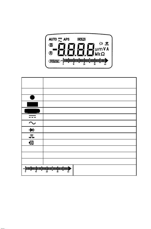
2.4 LCD Display Illustration
R
APS
AUTO
HOLD
RS232C
mV
Mk
――――――――――――――――――――――――
Chapter 2 Names and Functions of Parts
Enable Auto power save
Indicates AUTO range Mode
R
Indicates MANUAL range Mode
Data hold annunciator
Enable RS-232C
Direct Current or Voltage
Alternating Current or Voltage
Diode Check
Continuity function annunciator
Low battery indicator
Units of Voltage measurement
Units of Current measurement
m
Units of Resistance (ohm) measurement
Ω
Bar-graph indicator
Page 67

―――――――――――――――――――――――――――
Chapter 3
Measurement
Procedures
DANGER
Observe the following precautions to avoid
electric shock.
Always verify the appropriate setting of the
function selector before connecting the test
leads.
Disconnect the test leads from the
measurement object before switching the
function selector.
9
NOTE
――――――――――――――――――――――――
Accurate measurement may be impossible in the
presence of strong magnetic fields, such as near
transformers and high-current conductors, or in the
presence of strong electromagnetic fields such as
near radio transmitters.
Chapter 3 Measurement Procedures
Page 68

10
―――――――――――――――――――――――――――
Preparation for Measurement
The safety caps are attached to the test leads.
Remove these caps before connecting to the unit.
――――――――――――――――――――――――
Chapter 3 Measurement Procedures
Page 69

―――――――――――――――――――――――――――
11
3.1 Pre-Operation inspection
To avoid the possibility of electric shock or incorrect
measurement, check the following items before using
the product. If the operation check reveals any
abnormalities, stop the check immediately and do not
use the product.
WARNING
Before using the product check that the body of
the product is not damaged. Also make sure that
the insulation on the test leads is undamaged and
that no bare conductors are improperly exposed.
Using the product in such conditions could cause
an electric shock accident may occur, so contact
your dealer or Hioki representative for repair.
For voltage measurement, short the test leads and
check that 0 V is displayed.
For Measuring Resistance or Continuity Check,
short the test leads and check that 0 Ω is displayed.
Measure a test item with a known value (battery,
AC supply, resistor, etc.) to confirm that the
known value can be displayed.
NOTE
Periodic calibration and inspecton is necessary in
order to ensure that this product operates according
to its product specifications.
――――――――――――――――――――――――
Chapter 3 Measurement Procedures
Page 70

12
―――――――――――――――――――――――――――
3.2 Voltage Measurement
DANGER
The maximum input voltage is 1000 V DC, 1000
V rms or 10
6
V Hz. Attempting to measure
voltage in excess of the maximum input could
destroy the product and result in personal
injury or death.
To avoid electrical shock, be careful to avoid
shorting live lines with the test leads.
For safety, test lead connections must always
be made at the secondary side of a circuit
breaker.
――――――――――――――――――――――――
Chapter 3 Measurement Procedures
Page 71

―――――――――――――――――――――――――――
13
3.2.1 AC Voltage Measurement
NOTE
(1) Set the rotary switch to "
"
/ V ".
In the case of "
/ V ", press
V"or
SHIFT
button
momentarily to cycle through DC, AC tests.
(2) Connect the black test lead to "COM" terminal
and red test lead to "
" terminal.
(3) Touch the test leads to the test points and read
the display.
The display value may sometimes fluctuate even
when the multimeter is not switched on. This is due
to induced voltage, and is not a malfunction.
――――――――――――――――――――――――
Chapter 3 Measurement Procedures
Page 72

14
―――――――――――――――――――――――――――
3.2.2 DC Voltage Measurement
NOTE
(1) Set the rotary switch to "
(2) Push
button momentarily to set DC test.
SHIFT
/ V ".
(3) Connect the black test lead to "COM" terminal
and red test lead to "
" terminal.
(4) Touch the test leads to the test points and read
the display.
The display value may sometimes fluctuate even
when the multimeter is not switched on. This is due
to induced voltage, and is not a malfunction.
――――――――――――――――――――――――
Chapter 3 Measurement Procedures
Page 73

―――――――――――――――――――――――――――
15
3.3 Diode Check
DANGER
Never apply voltage to the test leads when the
Diode Check functions is selected. Doing so
may damage the product and result in personal
injury.
To avoid electrical accidents, remove power
from the circuit before measuring.
A good diode allows current to flow in one direction
only. To test a diode, turn the power off, remove the
diode from the circuit, and proceed as follows:
(1) Set the rotary switch to "
" position.
(2) Connect the black test lead to "COM" terminal
and red test lead to "
" terminal.
(3) Touch the red lead to the positive side of the
diode and the black lead to the negative side.
The meter can display diode voltage to
approximately 1.999 V.
A typical voltage is 0.3 to 0.8 V.
――――――――――――――――――――――――
Chapter 3 Measurement Procedures
Page 74

16
―――――――――――――――――――――――――――
Reverse the test leads and measure the voltage
across the diode again. If the diode is:
Good : "OL" is displayed.
Shorted : Near 0 V drop is displayed in both
directions, and the beeper sounds
continuously.
Open : "OL" is displayed in both directions.
Repeat step (3) and (4) for other diodes.
――――――――――――――――――――――――
Chapter 3 Measurement Procedures
Page 75

―――――――――――――――――――――――――――
17
3.4 Resistance Measurement
DANGER
Never apply voltage to the test leads when the
Resistance, Continuity Check functions are
selected. Doing so may damage the product
and result in personal injury.
To avoid electrical accidents, remove power
from the circuit before measuring.
(1) Set the rotary switch to " ".
(2) Connect the black test lead to "COM" terminal
and red test lead to "
(3) Touch the test leads to resistor and read the
display.
(4) Press
button momentarily to toggle
SHIFT
CONTINUITY function ON/OFF. The
continuity range is 0 to 400.0 Ω.
(5) Momentarily pushing this button will only turn
the beeper off. While testing continuity, the
beeper will sound if the resistance falls below
345 counts. And it will stop if the resistance
exceeds 350 counts.
" terminal.
――――――――――――――――――――――――
Chapter 3 Measurement Procedures
Page 76

18
―――――――――――――――――――――――――――
――――――――――――――――――――――――
Chapter 3 Measurement Procedures
Page 77

―――――――――――――――――――――――――――
19
3.5 Current Measurement
DANGER
Never apply voltage to the test leads when a
current measurement function is selected.
Doing so may damage the product and result in
personal injury.
To avoid electrical accidents, remove power
from the circuit before connecting the test
leads.
WARNING
To prevent electrical accidents, do not use the
tester to measure current when the electric
potential is 600 V or greater. The current
function overload protection trips at either 600
V DC, 600 V rms.
――――――――――――――――――――――――
Chapter 3 Measurement Procedures
Page 78

20
―――――――――――――――――――――――――――
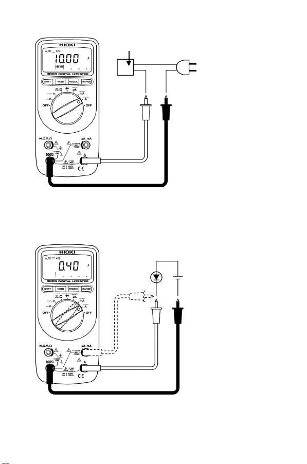
3.5.1 AC Current Measurement
NOTE
(1) Set the rotary switch to "
/ A ".
(2) Connect the black test lead to "COM" terminal
and red test lead to "A" terminal.
(3) Touch the test leads to the test points and read
the display.
If the reading is lower than 400 mA, to get better
resolution of display, please turn the rotary switch to
mA or μA position and remove the red test lead to
"μAmA" terminal.
Instrument operated by
alternatingcurrent
――――――――――――――――――――――――
Chapter 3 Measurement Procedures
Page 79

―――――――――――――――――――――――――――
21
3.5.2 DC Current Measurement
NOTE
(1) Set the rotary switch to "
(2) Push
button momentarily to set DC test.
SHIFT
/ A ".
(3) Connect the black test lead to "COM" terminal
and red test lead to "A" terminal.
(4) Touch the test leads to the test points and read
the display.
If the reading is lower than 400 mA, to get better
resolution of display, please turn the rotary switch to
mA or μA position and remove the red test lead to
"μAmA" terminal.
――――――――――――――――――――――――
Chapter 3 Measurement Procedures
Page 80

22
―――――――――――――――――――――――――――
――――――――――――――――――――――――
Chapter 3 Measurement Procedures
Page 81

―――――――――――――――――――――――――――
23
Chapter 4
Special Functions
Instructions
This multi-meter provides the operator with various
functions including:
(1) Data Hold
(2) Auto power Save
(3) Communication (RS-232C)
――――――――――――――――――――――――
Chapter 4 Special Functions Instructions
Page 82

24
―――――――――――――――――――――――――――
4.1 Data Hold
The data hold function allows operators to hold the
displayed digital value, while the analog bar graph
continues showing the present readings. Press
button to enter the data hold mode, and the
will be displayed. Press the button again to exit. The
present reading is now shown.
HOLD
HOLD
NOTE
――――――――――――――――――――――――
Chapter 4 Special Functions Instructions
The range is held in the case of auto range.
Page 83

―――――――――――――――――――――――――――
25
4.2 Auto Power Save
The instrument will auto power save within 30
minutes, if the functions are not changed. When
power-off happens, the finial data is saved. You can
push any buttons to wake-up meter, the display will
indicate the finial data and the data hold has been
enabled.
DISABLE AUTO POWER SAVE
When the meter is to be used for long periods of
time, the operator might want to disable the auto
power save. Once the auto power save function is
disabled, the meter will stay on continuously. The
meter will shut off by turning the rotary switch to
the off position.
Press and hold
SHIFTorRANGEorRS232
then turn on rotary switch to any positions, until the
buzzer sounds a tone to release pushing buttons. The
annunicator of APS will turn off.
button,
NOTE
If you turn the rotary switch to other positions to
wake-up meter, the finial data will not keep.
――――――――――――――――――――――――
Chapter 4 Special Functions Instructions
Page 84

26
―――――――――――――――――――――――――――
4.3 Communication (Option)
This instrument is equipped with an RS-232C
interface-based data transmission function. If this
instrument is connected to a personal computer,
measurement data can be transferred from this
instrument to the computer where it can be recorded
and saved.
NOTE
In order to use this function, one of the following
options is required. Purchase the option that is
appropriate for your computer.
When connecting to a serial port (D-sub 9-pin
connector) on the computer side 3856-01
COMMUNICATION PACKAGE (RS-232C)
When connecting to a USB port on the computer side
3856-02 COMMUNICATION PACKAGE (USB)
See Model 3856-01 or Model 3856-02 Instruction Manual
(1) Install the software in the personal computer.
See Model 3856-01 or Model 3856-02 Instruction Manual
(2) Installing the USB Driver (when using the 3856-02)
Installs the USB Driver when the 3856-02
Communications Package is used.
See Model 3856-01 or Model 3856-02 Instruction Manual
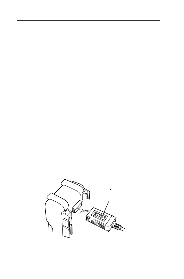
(3) Connect the optical connector of the
communications cable to the connector on the
holster for the 3803.
――――――――――――――――――――――――
Chapter 4 Special Functions Instructions
Page 85

―――――――――――――――――――――――――――
Make sure "RS-232C
INTERFACE" is
facing downwards
27
(4) Connect the other end of the communications
cable to the personal computer. (COM1 to
COM4)
(5) Press the
RS232C
then you will find that the annunciator of
button on the multimeter,
RS232
is light on the display.
NOTE
In the case of 3856-02 (USB), there is sometimes a
possibility of communication signal interference
with other USB devices (mouse, etc.), so always
press the
RS232C
button on the multimeter after
connecting with the communication cable.
(6) Start the software. The measurement data is
transferred from the 3803 to the personal
computer.
For operation instructions, please refer to Help.
NOTE
The Help function is not compatible with
Windows Vista.
During software installation, when the folder in
――――――――――――――――――――――――
Chapter 4 Special Functions Instructions
Page 86

28
―――――――――――――――――――――――――――
the copied location is deeply embedded, the
software may sometimes not be able to initialize
even when it is executed. In this case, copy the
file in a shallower folder such as the desktop and
execute it again.
NOTE
When there is no communication, this could be
because the COM ports of the PC and the software
are not aligned. Choose the same COM port as the
PC in the [Setup] - [COM Port] of the software.
See Model 3856-01 or Model 3856-02 Instruction Manual
When the COM ports
are not aligned, [Error
Could not Connect] will
be displayed.
――――――――――――――――――――――――
Chapter 4 Special Functions Instructions
Page 87

―――――――――――――――――――――――――――
29
Chapter 5
Specifications
5.1 General Specifications
Measurement
Mode
AC measurement
Mode
Function
Additional
Function
Type of Display
Display
Range
Selection
Measuring Rate
The liquid crystal display (LCD) is 4 digits with
maximum reading 3999 counts.
41 segments analog bar graph and full
annunciator
Automatic polarity indication.
――――――――――――――――――――――――
Dual integration
Mean measurement mode
DCV, ACV, DCA, ACA, OHM, Diode
check, Audible continuity tests.
Auto Range function
Data hold function
Auto Power Save function
Low Battery Indicate function
RS-232C Interface
LCD
Automatic or Manual / Manual Range
1.3 times per second.
Chapter 5 Specifications
Page 88

30
―――――――――――――――――――――――――――
Constituent
Inputs
Power Supply
Low Battery
Indicator
Dimension
Mass
Dielectric Strength
Electrical
Specifications
Temperature
Coefficient
Noise
Rejection
Rated Supply
Voltage
V, Ω, Audible continuity, Diode, Terminal
μA, mA Terminal
A Terminal
COM Terminal
4 Terminal components
6F22 manganese battery X 1 (9 V)
The " " appears when the battery
voltage drops below 6.3 to 7.5V
(approx.).
Approx. 76W X167H X33D mm
Approx. 2.99"W X6.54"H X1.30"D
Approx. 300 g
Approx. 10.6 oz. (with a battery included)
Approx. 400 g
Approx. 14.1 oz. (with a battery and
protective holster)
6 kVrms sin (1 minute at 50/60 Hz)
Accuracy: See the Accuracy Chart (See 5.2)
Accuracy Guarantee: 23
), less than 80% RH (no condensation)
Supply Voltage: 9 V to Low Battery
Indicator appears
specified accuracy×0.15/
(from 0 to 18 or 28 to 40 )
(from 32 to 64
NMRR DCV: more than -60 dB (50/60 Hz)
CMRR DCV: more than -120 dB (50/60 Hz)
ACV: more than -60 dB (50/60 Hz)
(1 kΩ Unbalance)
9.0VDC×1 (6F22 manganese battery)
or 82 to 104 )
5 (73 5
――――――――――――――――――――――――
Chapter 5 Specifications
Page 89

―――――――――――――――――――――――――――
Rated
Power
Continuous
Operating
Time
Operating
Temperature
Storage
Temperature
Location for Use
Accessories
Option
Protective
Fuse
15 mVA (Typ.)
(DCV Supply Voltage=9.0 V)
50 mVA (Max.)
(Diode (RS232-C) Supply Voltage=9.0 V)
Approx. 200 hours (DCV Function at 6F22
manganese battery)
0to40 (32 to 104 ) less than 80% RH
(no condensation)
-20 to 60 (-4 to 140 ) less than 80% RH
(no condensation)
Indoors, altitude up to 2000 m
3851-10 TEST LEAD (a pair)
Protective holster
Manual
6F22 manganese battery (built in)
3851-10 TEST LEAD (a pair)
Protective holster
3853 CARRYING CASE
3854 RS-232C PACKAGE
mA
μA
D086483P (Made by FERRAZ Inc.)
0.5 A/660 V, φ 6.35-32 mm, Breaking Capacity
30 kA
or 70125 (Made by SIBA Inc.)
0.5 A/700 V, φ 6.35-32 mm, Breaking Capacity
50 kA
A
TDC600 (Made by Cooper Bussmann Inc.)
10 A/600 V, φ 6.35-25.35 mm, Breaking
Capacity 10 kA
31
――――――――――――――――――――――――
Chapter 5 Specifications
Page 90

32
―――――――――――――――――――――――――――
Applicable
Standards
Safety
EMC
EN 61010
Pollution 2, Measurement Category II
(1000 V), Measurement Category III
(600 V)
(anticipated transient overvoltage
6000 V)
EN61326
――――――――――――――――――――――――
Chapter 5 Specifications
Page 91

―――――――――――――――――――――――――――
33
5.2 Accuracy Chart
Temperature and humidity for guaranteed accuracy
23 5 (73 9 ), 80% RH or less, no condensation
Guaranteed accuracy period
1year
(1) DC VOLTAGE
Range Resolution Accuracy
400.0 mV 0.1 mV
4.000 V 1mV
40.00 V 10 mV
400.0 V 0.1 V
1000 V 1V
Input Impedance: 10 MΩ
0.6%rdg. 2dgt.
(2) AC VOLTAGE
-1. 40 Hz to 200 Hz
Range Resolution Accuracy
400.0 mV 0.1 mV 2%rdg. 10dgt.
4.000 V 1mV
400.0 V 0.1 V
1000 V 1V 2.2%rdg. 5dgt.
2%rdg. 2dgt.40.00 V 10 mV
Overload
Protection
1000 V DC/
1000 V rms
6
V Hz
or 10
Overload
Protection
1000 V DC/
1000 V rms
6
V Hz
or 10
――――――――――――――――――――――――
Chapter 5 Specifications
Page 92

34
―――――――――――――――――――――――――――
-2. 200 Hz to 500 Hz
Range Resolution Accuracy
400.0 mV 0.1 mV -
4.000 V 1mV
2%rdg. 2dgt.40.00 V 10 mV
400.0 V 0.1 V
1000 V 1V 2.2%rdg. 5dgt.
Input Impedance: 10 MΩ
Overload
Protection
1000 V DC/
1000 V rms
6
V Hz
or 10
(3) DC CURRENT
Range
400.0 μA 0.1 μA
4000 μA 1 μA 50 Ω
40.00 mA 10 μA 5 Ω
400.0 mA 0.1 mA 0.5 Ω
10.00 A 10 mA 1.5%rdg. 5dgt. 0.05 Ω
10 A continuous, 10 to 20 A for 15 seconds maximum with 5
minutes cool down interval.
Resolu-
tion
Accuracy
1.5%rdg. 2dgt.
Internal
Resistance
(approx)
500 Ω
Overload
Protection
0.5 A/600 V
Quick
Acting Fuse
10 A/600 V
Quick
Acting Fuse
(4) AC CURRENT
40 Hz to 500 Hz
Range
400.0 μA 0.1 μA
4000 μA 1 μA 50 Ω
40.00 mA 10 μA 5 Ω
400.0 mA 0.1 mA 0.5 Ω
10.00 A 10 mA 2%rdg. 5dgt. 0.05 Ω
10 A continuous, 10 to 20 A for 15 seconds maximum with 5
minutes cool down interval.
――――――――――――――――――――――――
Chapter 5 Specifications
Resolut
-ion
Accuracy
2%rdg. 2dgt.
Internal
Resistance
(approx)
500 Ω
Overload
Protection
0.5 A/600 V
Quick
Acting Fuse
10 A/600 V
Quick
Acting Fuse
Page 93

―――――――――――――――――――――――――――
35
(5) RESISTANCE
Range
400.0 Ω 0.1 Ω
4.000 kΩ 1 Ω
40.00 kΩ 10 Ω
400.0 kΩ 100 Ω
4.000 MΩ 1kΩ 1.2%rdg. 3dgt.
40.00 MΩ 10 kΩ 2%rdg. 3dgt.
Resolut
-ion
Accuracy
0.6%rdg. 3dgt.
Maximum
Test
Voltage
1.2 V
max.
0.45 V
max.
Overload
Protection
600 V DC/
600 V rms
(6) AUDIBLE CONTINUITY TEST
Range Threshold Level
The beeper will sound if the
400.0Ω
resistance falls below 34.5 Ω.
And it will stop if the resistance
exceeds 35.0 Ω.
The measurement accuracy and open terminal voltage (test voltage)
are the same as these of Ω function.
Overload
Protection
600 V DC/
600 V rms
(7) DIODE CHECK
Range
1.999 V
Resolution
Accuracy
1mV
1.0%rdg. 2dgt.
Test Current
Voltage
approx. 1.65 mA
Less than 3 V
Overload
Protection
600 V DC/
600 V rms
――――――――――――――――――――――――
Chapter 5 Specifications
Page 94

36
―――――――――――――――――――――――――――
――――――――――――――――――――――――
Chapter 5 Specifications
Page 95

―――――――――――――――――――――――――――
37
Chapter 6
Maintenance and
Service
6.1 Changing the Battery and Fuses
WARNING
To avoid electric shock when replacing the
battery and fuse, first disconnect the test leads
from the object to be measured, then open the
cover.
After replacing the battery or fuse, replace the
cover and screws before using the product.
When replacing the battery, Be sure to insert
them with the correct polarity. Otherwise, poor
performance or damage from battery leakage
could result. Replace battery only with the
specified type.
To avoid the possibilit y of explosion, do not short
circuit, disassemble or incinerate battery.
Handle and dispose of battery in accordance with
local regulations.
Replace the fuse only with one of the specified
characteristics and voltage and current ratings.
Using a non-specified fuse or shorting the fuse
holder may cause a life-threatening hazard.
――――――――――――――――――――――――
Chapter 6 Maintenance and Service
Page 96

38
―――――――――――――――――――――――――――
Use the following procedures to replace the battery,
or fuse.
(1) Using the rotary switch to turn the meter off,
and remove the test leads from terminals.
(2) Loosen 3 screws on bottom cover, pull up and
move the cover.
(3) Replace the defective battery.
The meter is powered by a 6F22 battery. Replace
battery if the low battery sign (
) is displayed
and flashes.
(4) Remove the defective fuse by gently prying one
end of the fuse loose and sliding the fuse out of
the fuse bracket.
Install a new fuse of the same size and rating.
Make sure the new fuse is centered in the fuse
holder. There are 2 types of fuses, one for the
μA , mA terminal and one for the A terminal.
Be sure to set the correct fuse.
(5) Reverse the procedure of opening cover to close
the bottom cover.
――――――――――――――――――――――――
Chapter 6 Maintenance and Service
Page 97

―――――――――――――――――――――――――――
y
For μA mA terminal fuse :
D086483P
(Made by FERRAZ Inc.)
F0.5A/660V, 6.35mm-
6F22 manganese batter
32mm dia.
or 70125
(Made bySIBA Inc.)
0.5 A/700 V, 6.35-32 mm
dia.
For A terminal fuse :
TDC600 (Made by Cooper
Bussmann Inc.)
10A/600V, 6.35 mm-25.35
mm dia.
39
――――――――――――――――――――――――
Chapter 6 Maintenance and Service
Page 98

40
―――――――――――――――――――――――――――
6.2 Cleaning
To clean the product, wipe it gently with a soft
cloth moistened with water or mild detergent. Never
use solvents such as benzene, alcohol, acetone,
ether, ketones, thinners or gasoline, as they can
deform and discolor the case.
6.3 Service
If the product seems to be malfunctioning, confirm
that the battery are not discharged, and that the test
leads, and fuse are not open circuited before
contacting your dealer or Hioki representative.
When sending the product for repair, pack the
product carefully so that it will not be damaged
during shipment, and include a detailed written
description of the problem. Hioki cannot be
responsible for damage that occurs during shipment.
――――――――――――――――――――――――
Chapter 6 Maintenance and Service
Page 99

Page 100

 Loading...