

Hioki 3801-50, 3802-50 Operation Manual

DIGITAL HiTESTER
REMOTE OPERATION MANUAL
3801-50
3802-50


Contents
i
Contents
Introduction.................................................................................1
Symbols......................................................................................1
Chapter 1
Remote Interface Overview____________________ 3
Chapter 2
Setting Remote Interface Parameters ___________ 5
Chapter 3
Commands Summary ________________________ 7
Chapter 4
Responding Message ________________________ 9
Chapter 5
Instructions of Command Sets________________ 13
5.1 IEEE 488 Common Commands..................................13
5.2 SCPI Commands ........................................................14
Chapter 6
Summary of SCPI Commands ________________ 27
Chapter 7
Remote Program Example Using Visual Basic 6 _ 31

Contents
ii
1
Introduction
Introduction
The Section describes how to operate the meter via an optical
interface.
• It also explains the detail information of all interface command sets
of Standard Commands for Programmable Inst ruments (SCPI) used
in the meter.
• The remote control operation enables the user either to manually
operate the meter via a terminal or to execute a host computer
program automatically.
Trademars
Visual Basic is a registered trademark of Microsoft Corporation in the
United States and/or other countries.
Symbols
Safety Symbol
The following symbols in this manual indicate the relative importance
of cautions and warnings.
Other symbols
Indicates advisory items related to performance or
correct operation of the instrument.
Indicates the refere nce.
*
Iterminology explained at the bottom of the word.

Symbols
2
3
Chapter 1 Remote Interface Overview
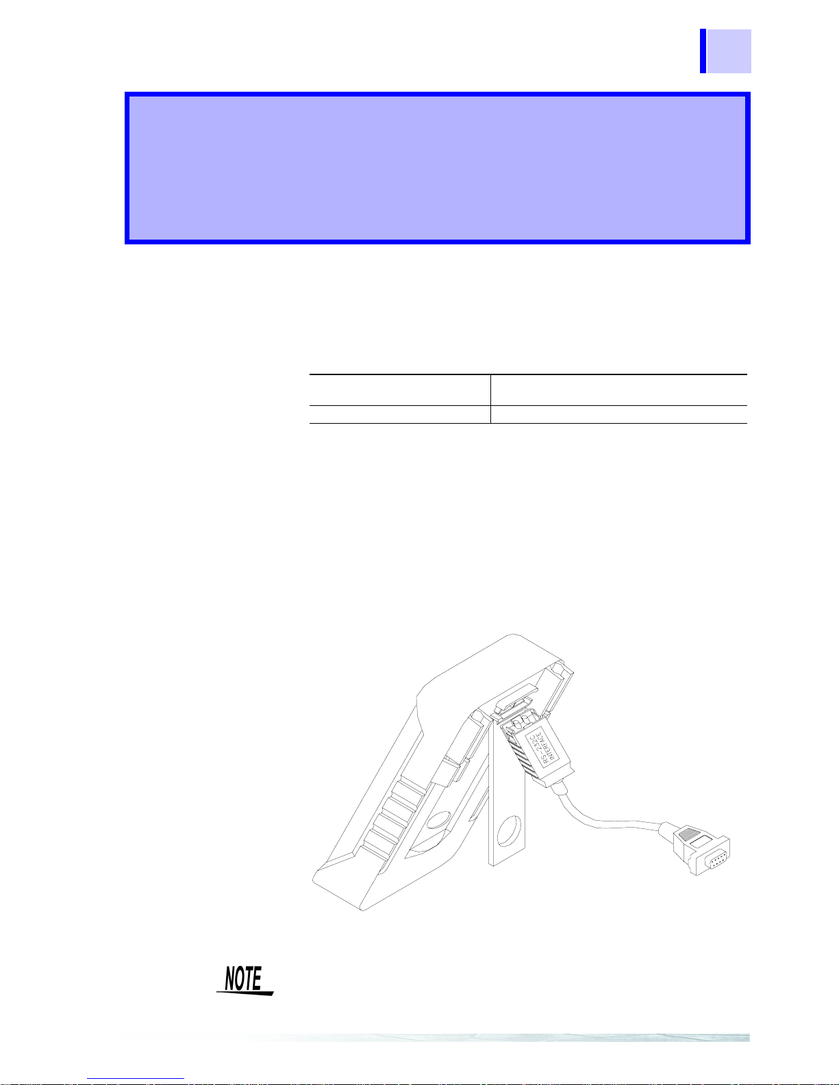
Fig. 1 shows a connection between the 3801-50/ 3802-50 and a computer via
an optical cable.
Either a USB or an RS-232C interface optical cable can be used for
communication.
Procedure
1. Connect the cable to the connector or USB port.
2. Once the USB cable is connected and the USB driver is installed, a
virtual RS-232COM port is created on the computer . (Only when using
a USB optical cable)
• The remote interface is a serial binary data interchange, which
operates from 2400 to 19200 baud rate.
• The communication port of the 3801-50, 3802-50 is designed in full
duplex, which makes the meter more reliable and efficient in data
taking.
Cable connection for Communication
Remote Interface
Overview Chapter 1
RS-232C interface optical
cable
to the 9-pin Type D male connector on the
computer.
USB optical cable
Connect to the USB port on the computer.
When connecting the communication cable to the meter, ensure that
the label RS-232C INTERFACE label faces upwards as shown in
Fig. 1.

Chapter 1 Remote Interface Overview
4
5
Chapter 2 Setting Remote Interface Parameters
In order to operate the meter via a host computer or terminal, the
parameters in interface withi n the 3801- 50, 38 02-50 ha ve to match t he
parameters in the serial interface provided by the host or terminal.
The following procedures will guide the user to set up interface
parameters within the 3801-50, 3802-50 to comply interface with the host.
The default settings of the meter at factory are 9600-baud rate, nonparity check , 8 data lengths, and 1 stop bit (9600, n, 8, 1).
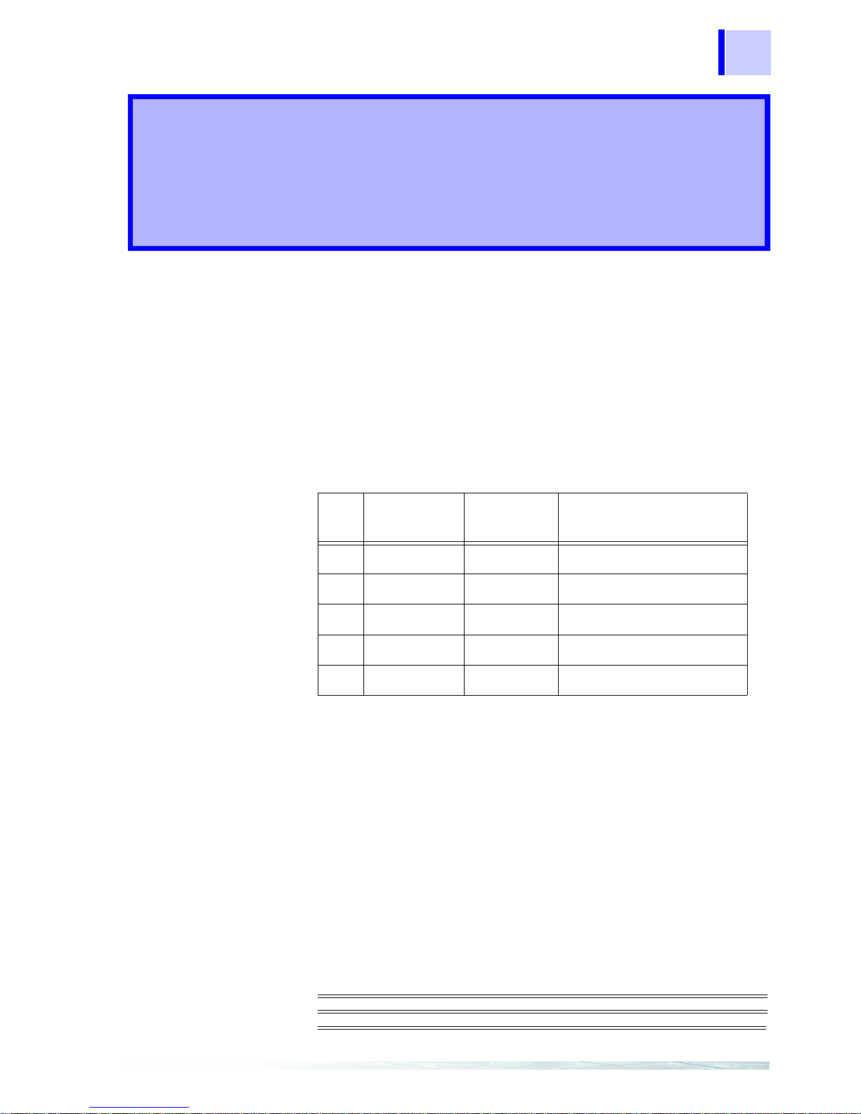
The following table indicates the factory settings and user selectable
communication parameters by using remote interface.
response
With response ON, the meter responsees (returns) all the characters
whatever it receives.
data output
• The remote indicator of the 3801-50, 3802-50 is flashing when the
meter is set to data output ON.
• If the remote interface of the 3801-50, 3802-50 is under data output
mode, the 3801-50, 3802-50 will print out the measured data when
the measurement cycle is completed.
• The 3801-50, 3802-50 auto-sends the newest data to a host
continuously.
• The 3801-50, 3802-50 doesn't accept any commands under data
output mode.
Setup Procedures for Communication Parameter
To ensure the remote interface will operate appropriately, user may
need to configure the remote interface parameters on power on
option. Please refer to operation procedures of POWER-ON OPTION.
❖3801-50, 3802-50 instruction manual ”Power-On Options”
Setting Remote Interface
Parameters Chapter 2
Remote Interface Parameters
Item Parameter
Factory
Setting
Selectable Parameter
1
Baud Rate 9600 2400, 4800, 9600, 19200
2
parity check None None, Odd or Even
3
data length 8 7 or 8
4
response OFF ON or OFF
5
data output OFF ON or OFF

Chapter 2 Setting Remote Interface Parameters
6
7
Chapter 3 Commands Summary
Overview of Command Type and Format
• All commands must be entered in the upper case.
• There are two types of the 3801-50, 3802-50 programming
commands: IEEE 488 common commands and Standard
Commands for Programmable Instruments (SCPI).
• Some commands are device-specific to the 3801-50, 3802-50. They
are not included in the version 1999.0 of the SCPI standard.
However, these commands are designed with the SCPI format in
mind and they follow the syntax rules of the standard.
Common Command Format
• The IEEE 488 standard defines the common commands as
commands that perform functions like reset and system query.
• Comm on commands usually come with the asterisk "∗" character,
and may include parameters. Some examples of Common
command like: *IDN?, *RST, *CLS, GTL, LLO.
SCPI Command Format and Query Format
• The SCPI commands control instrument functions.
• A subsystem command has a hierarchical structure that usually
consists of a top-level (or root) keyword, one or more lower level
keywords, and parameters.
• The following example shows a command and its associated query:
Commands
Summary Chapter 3
A. CONFigure:VOLTage:DC 0.5: Set the main display to the DC
voltage measurement , and
select the 510.00mV range.
B. CONFigure? : Return the function of the main
display measurement.
• CONFigure is a root level keyword with the second level
keyword, VOLTage, and 0.5 is the command parameter.
• The query command ends with a question mark "?".
SCPI stems from IEEE488.1 and IEEE 488.2. Although the IEEE
488.2 standard addressed some instrument measurements, it
principally dealt wi th common c ommands and syntax or data formats.
Please refer to the IEEE488.2 and SCPI reference manual for more
information.

Chapter 3 Commands Summary
8
Terminator
A terminator is a character sent by a host, which identifie s the end of a
command string. A valid terminator consists of two-byte data:
<CR> (Carriage Return, ASC(&H0D))
<LF> (Line Feed, ASC(&H0A))
 Loading...