

Page 1

取扱説明書
3802
ディジタルハイテスタ
Page 2

Page 3
―――――――――――――――――――――――――――――――
目次 1
目 次
はじめに
点検
安全について
ご使用にあたっての注意
1
1
1
4
第 1 章 各部の名称と機能
第 2 章 測定方法
2.1 電圧測定 11
2.1.1
2.1.2
2.2 抵抗測定
2.3 ダイオードチェック
2.4 コンデンサ容量測定
2.5 電流測定
2.5.1 μA 測定(400μA, 4000μA)
2.5.2 mA 測定(40 mA, 400 mA)
2.5.3 A 測定(10 A)
V ファンクションでの交流電圧測定 12
/ V, / mV ファンクションでの
電圧測定
第 3 章 応用測定
3.1 レコーディング機能 27
3.2 データホールド/リフレッシュホールド機能
3.2.1 データホールド機能
3.2.2 リフレッシュホールド機能
3.3 リラティブ(相対値表示)機能
3.4 バーグラフ表示
3.5 パワーセーブ機能
(オートパワーオフ機能およびスリープ機能) 31
3.6 表示カウント切換え機能
3.7 LCD ディスプレイ表示確認機能
3.8 抵抗測定による導通チェック機能
3.9 デュアルディスプレイ機能
3.10 RS-232C データ通信機能
3.11 電流入力端子誤挿入警告機能
3.12 パワーオンオプション
7
11
14
16
18
19
21
21
23
25
27
29
29
29
30
30
32
32
33
33
34
35
36
―――――――――――――――――――――――――――――――
Page 4

目次 2
―――――――――――――――――――――――――――――――
第 4 章 仕様
4.1 一般仕様 37
4.2 確度表
第 5 章 保守・サービス
5.1 電池およびヒューズの交換方法 43
5.1.1 電池交換
5.1.2 ヒューズ交換
5.2 本器のクリーニング
5.3 サービス
37
39
43
44
45
46
46
―――――――――――――――――――――――――――――――
Page 5

―――――――――――――――――――――――――――――――
1
はじめに
このたびは、HIOKI“3802 ディジタルハイテスタ”をご選定い
ただき、誠にありがとうございます。
この製品を十分にご活用いただき、また末長くご使用いただく
ためにも、取扱説明書はていねいに扱い、いつも手元に置いて
ご使用ください。
点検
本器がお手元に届きましたら、輸送中において異常または、破
損がないか点検してからご使用ください。万一破損あるいは仕
様どおり動作しない場合は、代理店(お買上店)か最寄りの営
業所にご連絡ください。
○付属品
3851-10 テストリード(赤黒各 1) 1
ホルスタ 1
取扱説明書 1
積層形マンガン乾電池(6F22)(本体内蔵、モニタ用) 1
安全について
この取扱説明書には、本器を安全に操作し、安全な状態を保つ
のに要する情報や注意事項が記載されています。本器を使用す
る前に、下記の安全に関する事項をよくお読みください。
この機器は IEC 61010 安全規格に従って、設計され、試
警告
験し、安全な状態で出荷されています。測定方法を間違
えると人身事故や機器の故障につながる可能性があり
ます。取扱説明書を熟読し、十分に内容を理解してから
操作してください。万一事故があっても、弊社製品が原
因である場合以外は責任を負いかねます。
―――――――――――――――――――――――――――――――
Page 6
2
―――――――――――――――――――――――――――――――
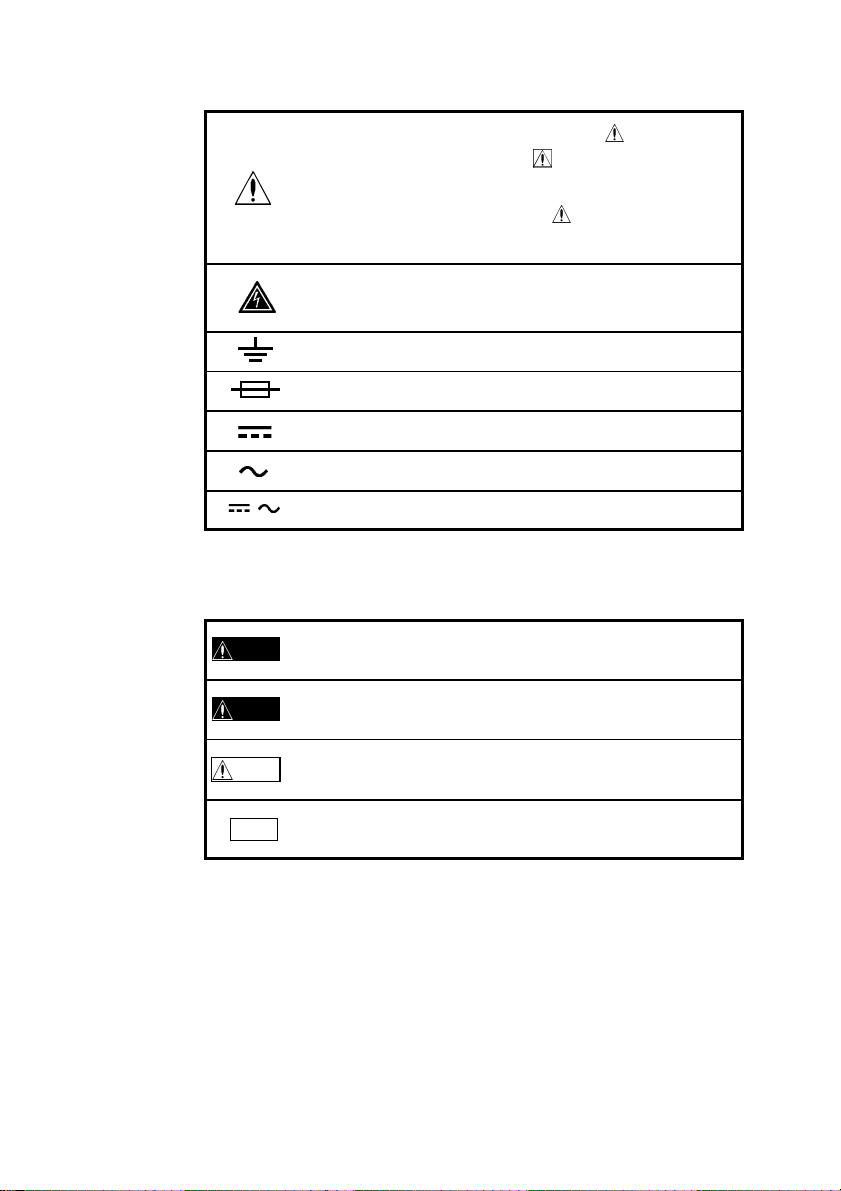
○安全記号
・使用者は、機器上に表示されている マークのとこ
ろについて、取扱説明書の
照し、機器の操作をしてください。
・使用者は、取扱説明書の中の
ず読み注意する必要があることを示します。
この端子には、危険な電圧がかかることを示します。
接地端子を示します。
ヒューズを示します。
直流(DC)を示します。
交流(AC)を示します。
直流(DC)または交流(AC)を示します。
/
○本取扱説明書の注意事項には重要度に応じて以下の表記がされ
ています。
操作や取扱いを誤ると、使用者が死亡または重傷につ
危険
ながる危険性が極めて高いことを意味します。
操作や取扱いを誤ると、使用者が死亡または重傷につ
警告
ながる可能性があることを意味します。
操作や取扱いを誤ると、使用者が傷害を負う場合、ま
注意
たは機器を損傷する可能性があることを意味します。
注記
製品性能および操作上でのアドバイス的なことを意味
します。
マークの該当箇所を参
マークのところは必
―――――――――――――――――――――――――――――――
Page 7
―――――――――――――――――――――――――――――――
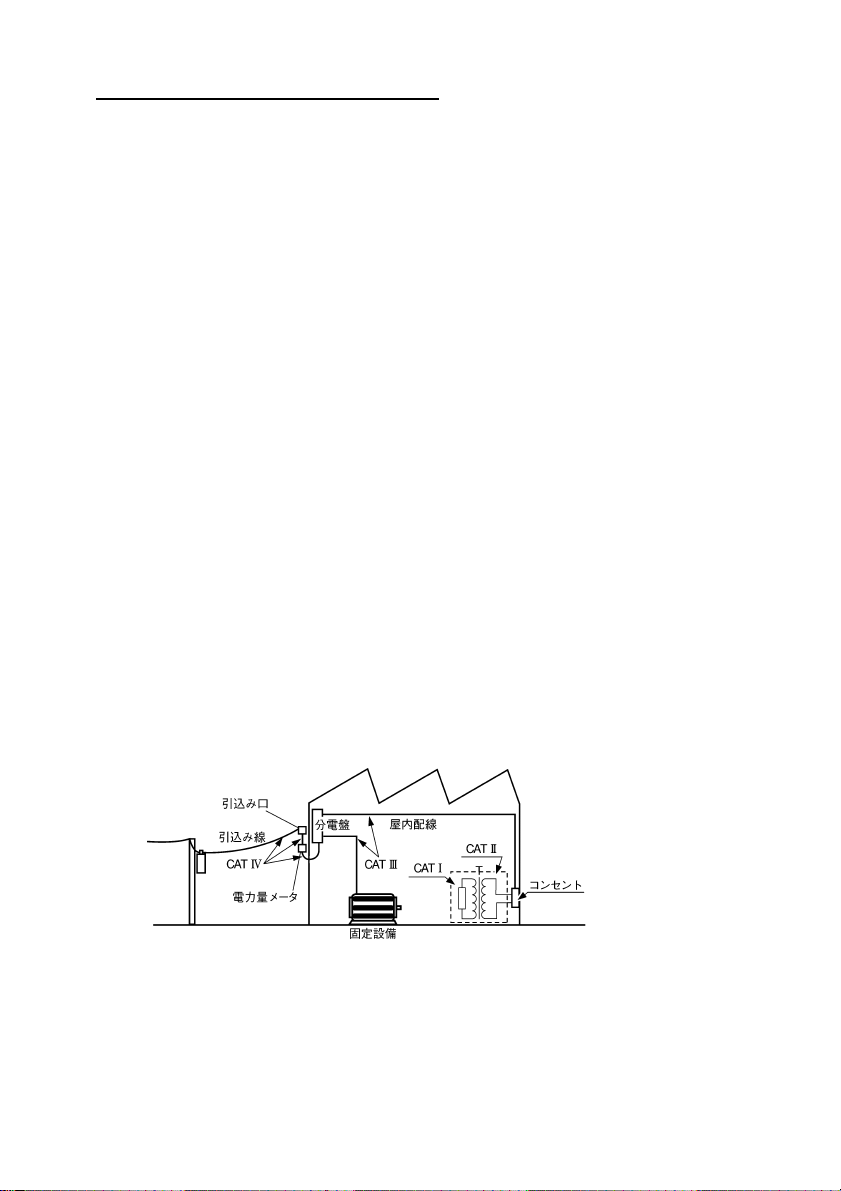
測定カテゴリ(過電圧カテゴリ)について
本器は CATII(1000V),CATIII(600V)に適合しています。
測定器を安全に使用するため、IEC61010 では測定カテゴリと
して、使用する場所により安全レベルの基準を CATⅠ~CATⅣ
で分類しています。概要は下記のようになります。
CATⅠ:コンセントからトランスなどを経由した機器内の二
次側の電気回路
CATⅡ:コンセントに接続する電源コード付き機器(可搬形工
具・家庭用電気製品など)の一次側電路
CATⅢ:直接分電盤から電気を取り込む機器(固定設備)の一
次側および分電盤からコンセントまでの電路
CATⅣ:建造物への引込み電路、引込み口から電力量メータお
よび一次側電流保護装置(分電盤)までの電路
数値の大きいカテゴリは、より高い瞬時的なエネルギーのある
電気環境を示します。そのため、CATⅢで設計された測定器は、
CATⅡで設計されたものより高い瞬時的なエネルギーに耐え
ることができます。
カテゴリの数値の小さいクラスの測定器で、数値の大きいクラ
スに該当する場所を測定すると重大な事故につながる恐れがあ
りますので、絶対に避けてください。
特に、CATⅠの測定器を CATⅡ、ⅢおよびⅣに該当する場所の
測定に用いないでください。
測定カテゴリは IEC60664 の過電圧カテゴリに対応します。
3
―――――――――――――――――――――――――――――――
Page 8
4
―――――――――――――――――――――――――――――――
ご使用にあたっての注意
●本器を安全にご使用いただくために、また機能を十分にご活用
いただくために、下記の注意事項をお守りください。
・測定前にファンクションスイッチの位置を確認して
危険
ください。電圧レンジ以外のレンジで電圧を測定す
ると、人身事故や本器の破損になります。スイッチを
切り換えるときは、被測定物からテストリードを外し
てください。
・抵抗測定、導通チェック、ダイオードチェックのファ
ンクションに電圧を入力しないでください。本器を
破損し、人身事故になります。
電気事故を防ぐため、測定回路の電源を切ってから、
測定してください。
・本器をぬらしたり、ぬれた手で測定しないでくださ
警告
い。感電事故の原因になります。
・電圧を入力したままケースを開放し、本器の調整、修
理はしないでください。もしそれが不可避の場合は、
危険を良く知った技能者の責任で行ってください。
・本器が被測定物に接続していると、端子類は危険な電
圧が加わっていることがあり、ケースを取り外すと生
きた部分が露出します。電池交換等のためにケース
を開く場合は、被測定物からテストリード等を外して
ください。
―――――――――――――――――――――――――――――――
Page 9
―――――――――――――――――――――――――――――――
・本器の保護機能が破損している場合は、使用できない
注意
ように廃棄するか、知らないで動作させることのない
ように、表示しておいてください。
・直射日光や高温、多湿、結露するような環境下での保
存、使用はしないでください。変形、絶縁劣化を起こ
し、仕様を満足しなくなります。
・本器は防じん・防水構造となっていません。ほこり
の多い環境や水のかかる環境下で使用しないでくだ
さい。故障の原因になります。
・安全のため、テストリードは付属の 3851-10 を使用し
てください。
・強力な電磁波を発生するもの、または帯電しているも
のの近くで使用しないでください。誤動作の原因と
なります。
●使用前の点検
使用前には、保存や輸送による故障がないか、点検と動作確認
をしてから使用してください。故障を確認した場合は、お買上
店(代理店)か最寄りの営業所にご連絡ください。
5
・リード線の被覆が破れたり、金属が露出していない
警告
か、使用する前に確認してください。損傷がある場合
は、感電事故になるので、指定の 3851-10 と交換して
ください。
―――――――――――――――――――――――――――――――
Page 10

6
―――――――――――――――――――――――――――――――
―――――――――――――――――――――――――――――――
Page 11
―――――――――――――――――――――――――――――――
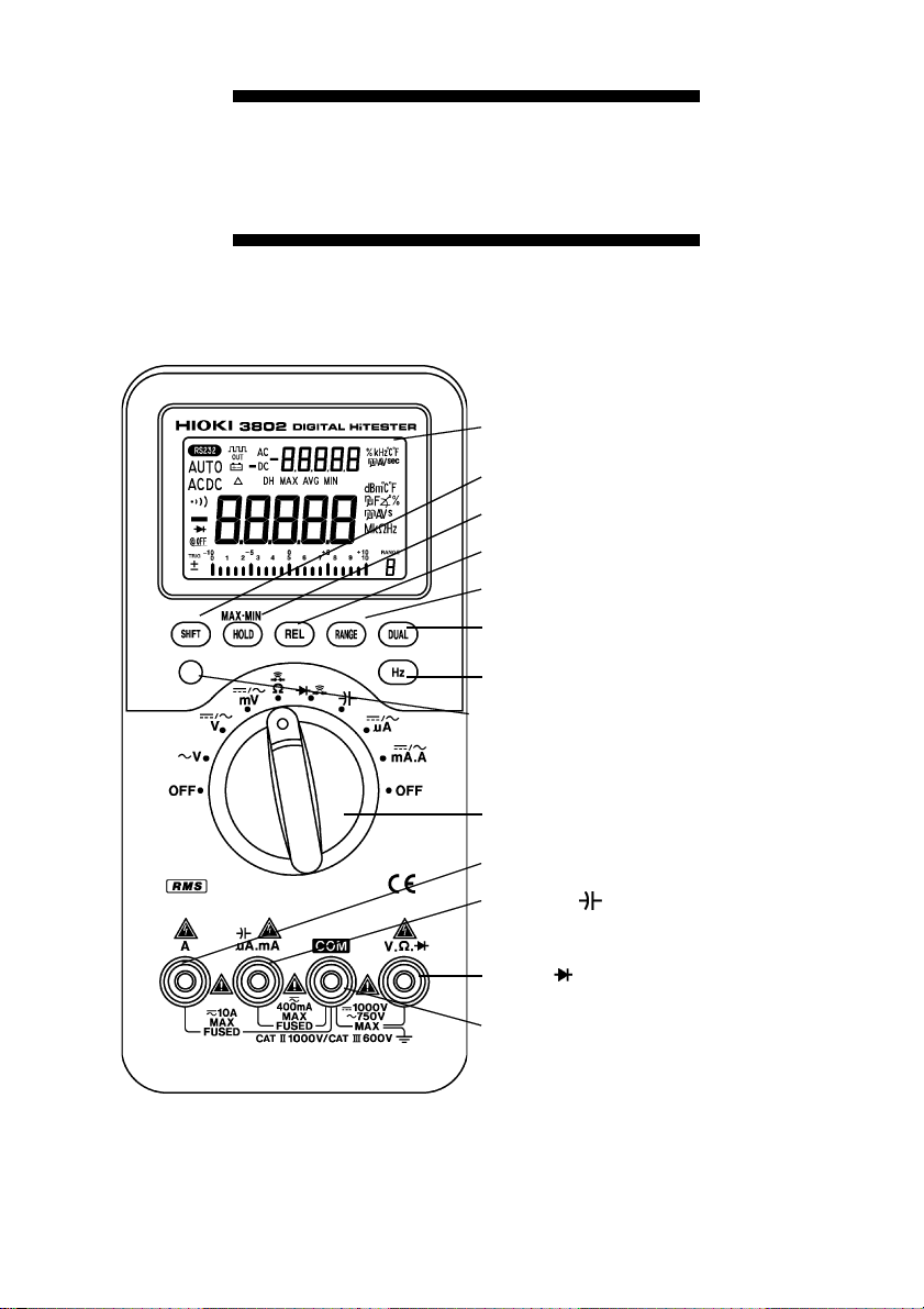
第1章 各部の名称と機能
⑬LCD ディスプレイ
②SHIFT キー
③HOLD/MAX・MIN キー
④REL キー
⑤RANGE キー
⑥DUAL キー
⑦Hz キー
⑧表示カウント
切換えキー
7
①ファンクション・
スイッチ
⑫A 端子
⑪μA.mA. 端子
⑨V・Ω・ 端子
⑩COM 端子
―――――――――――――――――――――――――――――――
第 1 章 各部の名称と機能
Page 12
8
―――――――――――――――――――――――――――――――
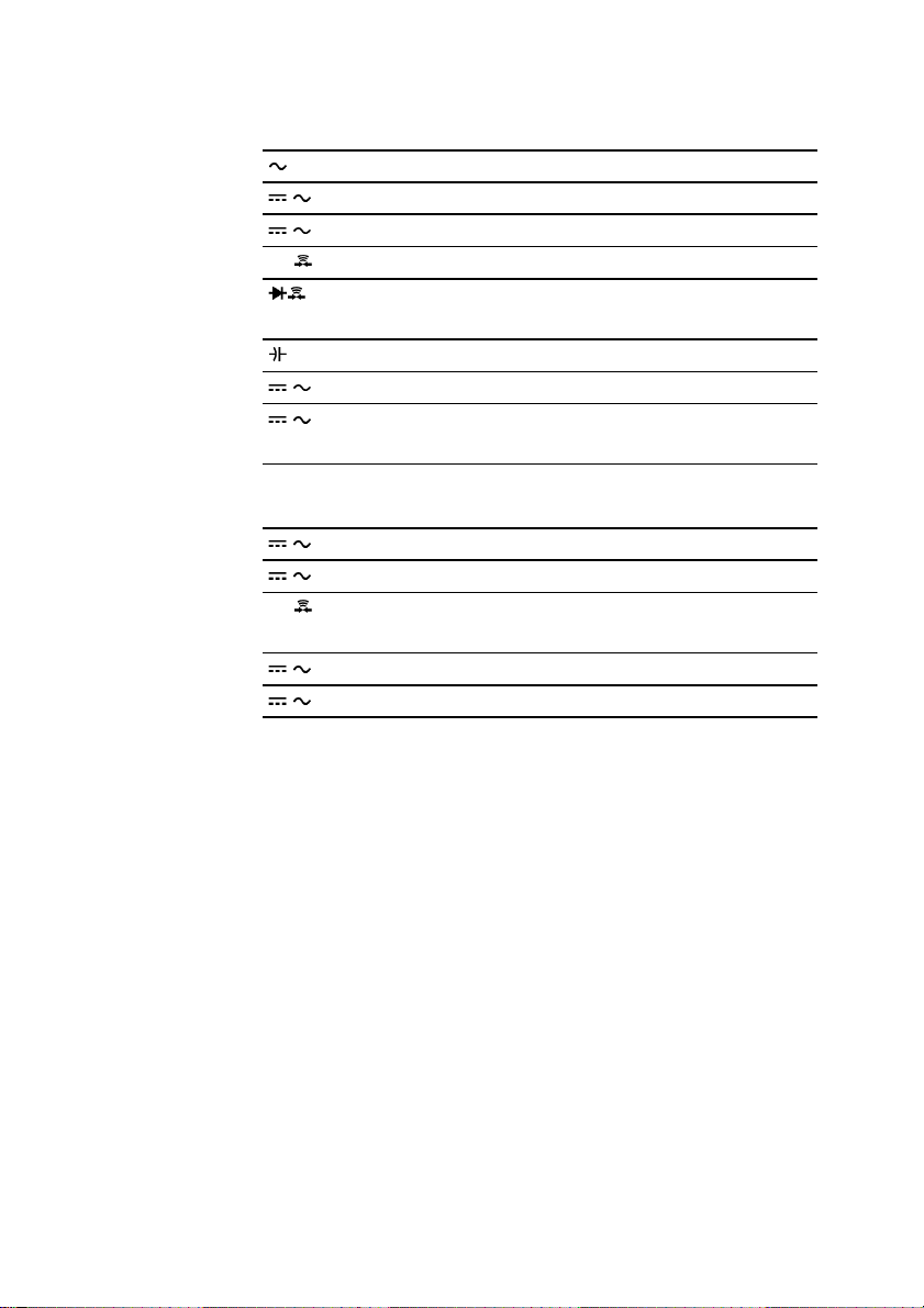
①ファンクション・スイッチ(ファンクション・SW)
ファンクションの選択、電源の ON/OFF を行います。
V
/ V
mV DC,AC電圧(~400 mV)
/
Ω/ 抵抗、(抵抗値による)導通チェック
μA DC,AC 400μA,4000μA
/
/ mA.A
②SHIFT キー
/ V
mV DC/ACを切り換えます。
/
Ω/ 抵抗/導通チェック(抵抗値による)を切り換え
μA DC/ACを切り換えます。
/
/ mA.A
ACカップリング電圧
DC,AC電圧
ダイオードチェック、
(電圧による)導通チェック
コンデンサ容量
DC,AC 40 mA,400 mA(mA端子使用時),
4 A,10 A(A端子使用時)
DC/ACを切り換えます。
ます。
DC/ACを切り換えます。
・Ωファンクション時に導通チェック機能の起動と解除を行い
ます。
③HOLD/MAX・MIN キー
・データホールド機能の起動と解除を行います。
・リフレッシュホールド機能の起動を行います(パワーオンオプ
ション、データホールド/リフレッシュホールド機能参照)。
④REL キー
・リラティブ(相対値表示)機能の起動と解除を行います(リラ
ティブ機能参照)。
⑤RANGE キー
・オートレンジ/マニュアルレンジを切り換えます。
・マニュアルレンジ時のレンジを切り換えます。
―――――――――――――――――――――――――――――――
第 1 章 各部の名称と機能
Page 13
―――――――――――――――――――――――――――――――
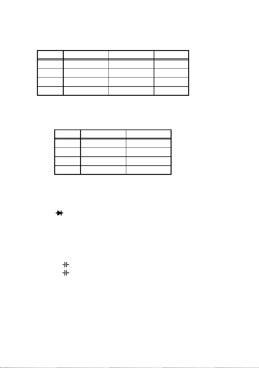
⑥DUAL キー
・デュアルディスプレイの各種の組み合わせを避択します。組み
合わせは以下の表の通りです。
測定項目 第1ディスプレイ 第2ディスプレイ 備考
ACV ACV Frequency
DCV DCV Frequency
ACA ACA Frequency
DCA DCA Frequency
⑦Hz キー
・デュアルディスプレイを利用して周波数測定を切り換えます。
デュアルディスプレイの組み合わせは以下の表の通りです。
測定項目 第1ディスプレイ 第2ディスプレイ
ACV Frequency(Hz) ACV
DCV Frequency(Hz) DCV
ACA Frequency(Hz) ACA
DCA Frequency(Hz) DCA
⑧表示カウント切換えキー
・1 秒以上押すことで、4000 カウント表示/40000 カウント表示を
切り換えます。
⑨V・Ω・
電圧、抵抗、ダイオードファンクションのときに使用する端子
です。
⑩COM 端子
各ファンクションの共通端子です。(テストリードの黒を接続
します)
⑪μA.mA.
μA.mA.
⑫A 端子
A ファンクションのときに使用する端子です。
端子
端子
.ファンクションのときに使用する端子です。
9
―――――――――――――――――――――――――――――――
第 1 章 各部の名称と機能
Page 14

10
―――――――――――――――――――――――――――――――
⑬LCD ディスプレイ
バーグラフ スケール表示 21ドットバーグラフ表示(極
性表示付)
パワーセーブ機能動作時に点灯
電池が確度保証電圧(約7.2 V)以下になった
ときに点滅
DC
AC
AUTO
△ リラティブ機能動作時に点灯
DH
MAX AVG
MIN
MAX
AVG
MIN
mμA
mV
MkΩ
kHz
RANGE 8
sec
nμF
DCV,DCmV,DCμA,DCmA,DCA時に点灯
ACV,ACmV,ACμA,ACmA時に点灯
オートレンジ動作時に点灯
データホールド機能動作時に点灯
レコーディング機能動作時に点灯
最大読取り値表示時に点灯
平均読取り値表示時に点灯
最小読取り値表示時に点灯
導通チェック時に点灯
ダイオードチェック時に点灯
電流測定時の単位
電圧測定時の単位
抵抗測定時の単位
周波数測定時の単位
各ファンクションでの測定レンジ
レコーディング機能およびタイマ機能動作時
に点灯
通信機能動作時に点灯
容量測定時の単位
―――――――――――――――――――――――――――――――
第 1 章 各部の名称と機能
Page 15
―――――――――――――――――――――――――――――――
11
第2章 測定方法
感電事故を防ぐため下記のことをお守りください。
警告
・端子部は、安全な絶縁距離がとれていません。テスト
リードの接続には注意してください。
・測定端子の差換えをともなうファンクションスイッ
チの切換えは、テストリードを被測定物からを外し、
端子から抜いてください。
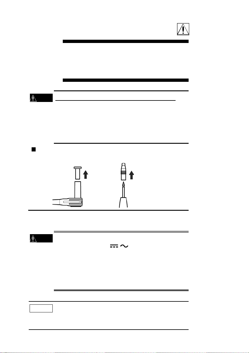
測定前の準備
テストリードについている保護キャップを外してください。
電圧測定
2.1
・最大入力電圧は、DC1200 V、AC850 Vrms、または 10
危険
V・Hz です。ただし、
大入力電圧は、DC600 V、AC600 Vrms、または 10
V・Hz です。最大入力電圧を超えると本器を破損し人
身事故になるので測定しないでください。
・感電事故を防ぐため、テストリードの先端で電圧のか
かっているラインを短絡しないでください。
注記
―――――――――――――――――――――――――――――――
トランスや大電流路など強磁界の発生している近く、ま
た無線機など強電界の発生している近くでは、正確な測
定ができない場合があります。
/ mV ファンクションの最
第 2 章 測定方法
6
6
Page 16

12
―――――――――――――――――――――――――――――――
2.1.1
(1) ファンクション・SW を
(2) 被測定回路にテストリードを接続し、表示の値を読みます。
(3) マニュアルレンジ操作の場合、RANGE キーを押します
(4) DUAL キーを押すと、デュアルディスプレイモードが設定
第 1 ディスプレイ 第 2 ディスプレイ
ACV Hz
↓ ↓
ACV 表示なし
(5) Hz キーを押すと、デュアルディスプレイモードによる周波
第 1 ディスプレイ 第 2 ディスプレイ
Hz ACV
V ファンクションでの交流電圧測定
V にします。赤のテストリード
を V・Ω・
(AUTO マークが消えます)。再びオートレンジにする場合
は、RANGE キーを 1 秒以上押します。
されます。DUAL キーを押すごとに以下のように表示が切
り換わります。
数測定機能が設定されます。デュアルディスプレイモード
を解除する場合は Hz キーを 1 秒以上押します。
端子に、黒を COM 端子に接続します。
周波数測定に対しても、RANGE キーによるオートレンジ/マニ
ュアルレンジ切換えが可能です。
―――――――――――――――――――――――――――――――
第 2 章 測定方法
Page 17

―――――――――――――――――――――――――――――――
0~750 VAC
(+)赤(-)
黒
13
―――――――――――――――――――――――――――――――
第 2 章 測定方法
Page 18
14
―――――――――――――――――――――――――――――――
2.1.2
(1) ファンクション・SW を測定する電圧に応じて
(2) 被測定回路にテストリードを接続し、表示の値を読みます。
(3) マニュアルレンジ操作の場合、RANGE キーを押します
(4) SHIFT キーを押すと、DCV(mV)/ACV(mV)測定が交互に切
(5) DUAL キーを押すと、デュアルディスプレイモードが設定
・DCV(mV)測定時
第 1 ディスプレイ 第 2 ディスプレイ
DCV(mV) Hz
↓ ↓
DCV(mV) 表示なし
・ACV(mV)測定時
第 1 ディスプレイ 第 2 ディスプレイ
ACV(mV) Hz
↓ ↓
ACV(mV) 表示なし
/ V,/ mV ファンクションでの電圧測定
/ V ま
たは
端子に、黒を COM 端子に接続します。
(AUTO マークが消えます)。再びオートレンジにする場合
は、RANGE キーを 1 秒以上押します。
り換わります。
されます。DUAL キーを押すごとに以下のように表示が切
り換わります。
/ mV にします。赤のテストリードを V・Ω・
(6) Hz キーを押すと、デュアルディスプレイモードによる周波
数測定機能が設定されます。デュアルディスプレイモード
を解除する場合は Hz キーを 1 秒以上押します。
第 1 ディスプレイ 第 2 ディスプレイ
Hz DCV(mV)/ACV(mV)
周波数測定に対しても RANGE キーによるオートレンジ/マニ
ュアルレンジ切換えが可能です。
注記
―――――――――――――――――――――――――――――――
第 2 章 測定方法
・TV のブラウン管電圧などを測定する場合には、1000
V レンジ(DCV)に固定して使用してください。
Page 19

―――――――――――――――――――――――――――――――
0~750 VAC,1000 VDC
(+)赤(-)
黒
15
0~400 mVAC/DC
(+)赤(-)
黒
―――――――――――――――――――――――――――――――
第 2 章 測定方法
Page 20

16
―――――――――――――――――――――――――――――――
抵抗測定
2.2
・抵抗測定のファンクションに電圧を入力しないでく
危険
ださい。本器を破損し、人身事故になります。
電気事故を防ぐため、測定回路の電源を切ってから、
測定してください。
(1) ファンクション・SW を
(2) 赤のテストリードを V・Ω・ 端子に、黒を COM 端子に接
続します。
(3) 被測定回路にテストリードを接続し、表示の値を読みます。
(4) マニュアルレンジ操作の場合、RANGE キーを押します
(AUTO マークが消えます)。再びオートレンジにする場合
は、RANGE キーを 1 秒以上押します。
(5) SHIFT キーを押すごとに導通チェック機能の起動/解除を
行います(
レンジは解除されます。
注記
・導通チェック機能の起動時には、各レンジの 100 カウ
ント(40000 カウント表示時は 1000 カウント)以下
の抵抗値の場合にブザーが鳴ります。
・導通チェック時に RANGE キーを 1 秒以上押してオ
ートレンジにしても
導通チェック動作は行いません。
マークが点灯/消灯します)。この時、オート
Ωにします。
マークは点灯していますが、
―――――――――――――――――――――――――――――――
第 2 章 測定方法
Page 21

―――――――――――――――――――――――――――――――
PUSH
PUSH
0~40 MΩ
(+)赤(-)
黒
17
―――――――――――――――――――――――――――――――
第 2 章 測定方法
Page 22
18
―――――――――――――――――――――――――――――――
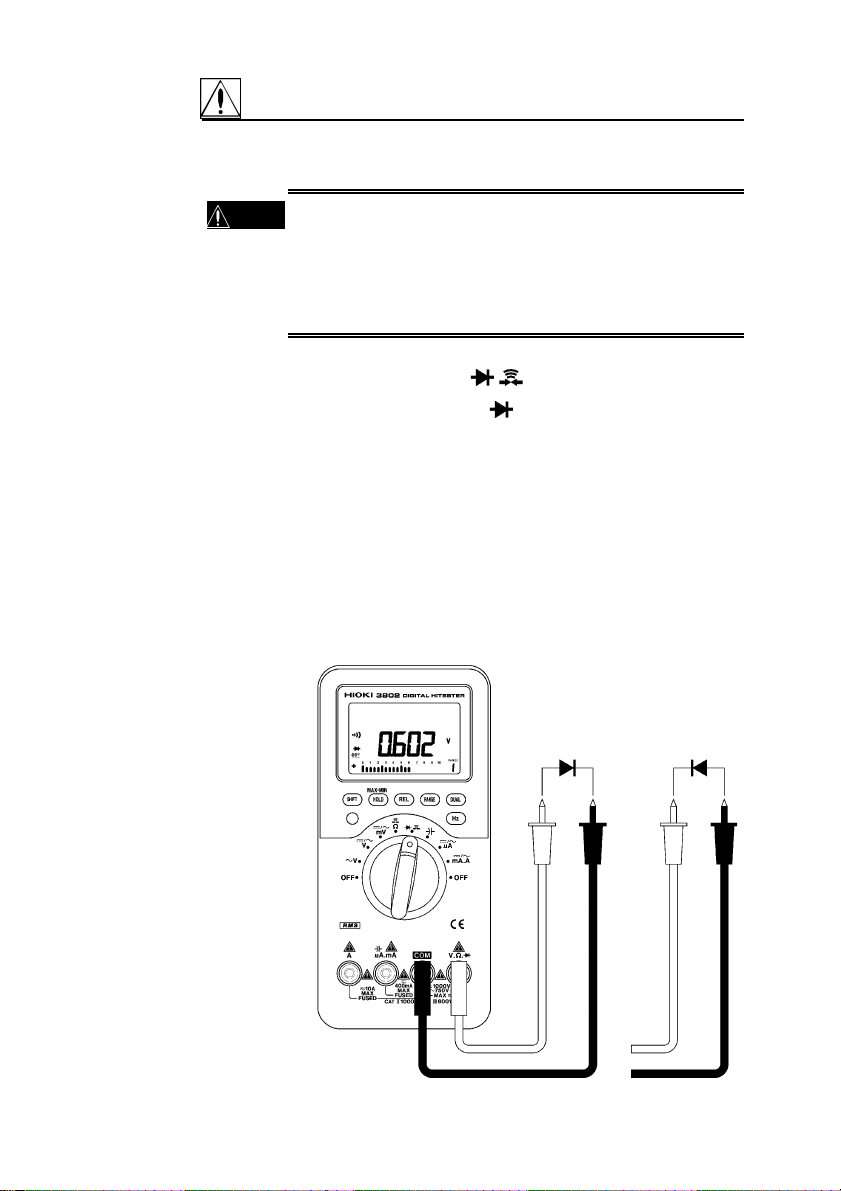
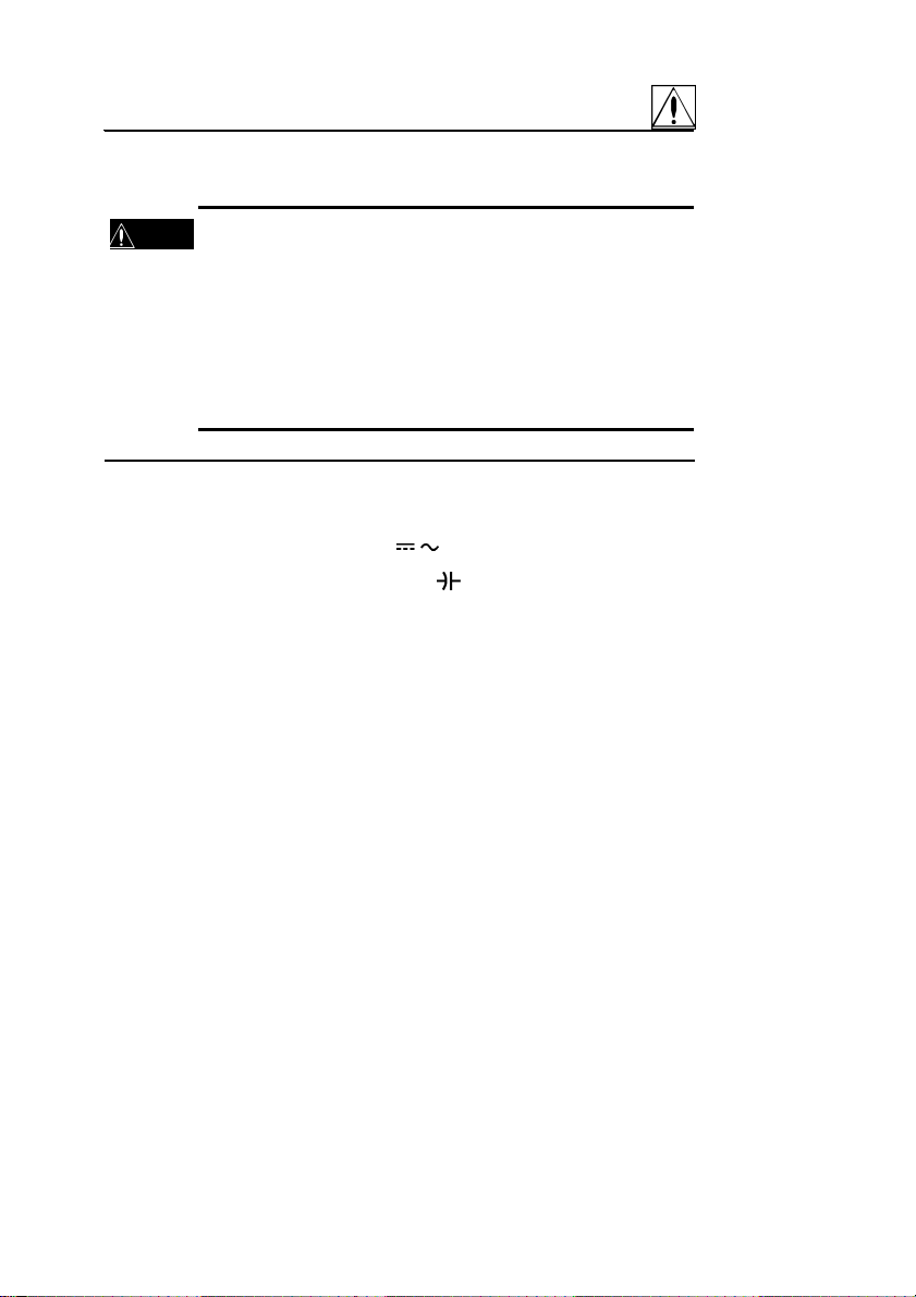
ダイオードチェック
2.3
・ダイオードチェックのファンクションに電圧を入力
危険
しないでください。本器を破損し、人身事故になりま
す。
電気事故を防ぐため、測定回路の電源を切ってから、
測定してください。
(1) ファンクション・SW を
(2) 赤のテストリードを V・Ω・ 端子に、黒を COM 端子に接
続します。
(3) 被測定回路にテストリードを接続します。
(4) 正常なシリコンダイオードでは、順方向電圧 0.4 V~0.7 V
を表示します。逆方向では、"OL"を表示します。ダイオー
ドが短絡している場合は 0V付近を(ブザーが鳴ります)、
断線している場合は順方向で"OL"を表示します。
(5) 測定電圧が約 0.1 V 以下のとき、ブザーが鳴ります(電圧に
よる導通チェック)。
にします。
順バイアス
逆バイアス
(+)赤(-)
黒
―――――――――――――――――――――――――――――――
第 2 章 測定方法
(+)赤(-)
黒
Page 23
―――――――――――――――――――――――――――――――
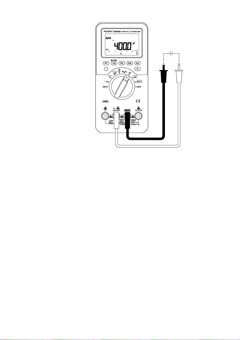
コンデンサ容量測定
2.4
・μA.mA. 端子に電圧を入力しないでください。本
危険
器を破損し、人身事故になります。
・チャージされていると思われるコンデンサは、両端を
警告
短絡させ放電してから測定してください。本器を破
損し、人身事故になります。
19
(1) ファンクション・SW を
(2) 赤のテストリードをμA.mA. 端子に、黒を COM 端子に
接続します。
(3) テストリードを開放し、REL キーを押して表示値をゼロに
します。
(4) 被測定回路にテストリードを接続し、表示の値を読みます。
注記
・極性のあるコンデンサを測定する場合には極性を守
ってください。
・測定の前にコンデンサを放電してください。
・低容量のコンデンサを測定する場合、付属のテストリ
ードを使用すると、テストリードの構造上人体からの
ノイズの影響で、測定値が安定しない可能性がありま
す。その場合には、9617 台付クリップ、9618 クリッ
プ形リード(オプション)等を用いて、人体から測定
物を離して測定してください。
にします。
―――――――――――――――――――――――――――――――
第 2 章 測定方法
Page 24
20
―――――――――――――――――――――――――――――――
0~9999μF
(+)
(-)
赤
黒
―――――――――――――――――――――――――――――――
第 2 章 測定方法
Page 25
―――――――――――――――――――――――――――――――
電流測定
2.5
・600 V 以上の電位の場合、回路内の電流測定は行わな
警告
いでください。電流ファンクションの過負荷保護は
AC600 V です。
・電気事故を防ぐため、測定回路の電源を一度切ってか
ら、テストリードを接続し、測定してください。
・電流レンジに電圧を入力しないでください。本器を
破損し、人身事故になります。
21
2.5.1 μA 測定(400μA, 4000μA)
(1) ファンクション・SW を /
(2) 赤のテストリードをμA.mA. 端子に、黒を COM 端子に
接続します。
(3) SHIFT キーを押して DC/AC を選択します。
(4) 被測定回路にテストリードを接続し、表示の値を読みます。
(5) マニュアルレンジ操作の場合、RANGE キーを押します
(AUTO マークが消えます)。再びオートレンジにする場合
は、RANGE キーを 1 秒以上押します。
(6) DUAL キーを押すと、デュアルディスプレイモードが設定
されます。DUAL キーを押すごとに以下のように表示が切
り換わります。
・DCμA 測定時
第 1 ディスプレイ 第 2 ディスプレイ
DCμA Hz
↓ ↓
DCμA 表示なし
・ACμA 測定時
第 1 ディスプレイ 第 2 ディスプレイ
ACμA Hz
↓ ↓
ACμA 表示なし
μA にします。
―――――――――――――――――――――――――――――――
第 2 章 測定方法
Page 26
22
―――――――――――――――――――――――――――――――
(7) Hz キーを押すと、デュアルディスプレイモードによる周波
数測定機能が設定されます。デュアルディスプレイモード
を解除する場合は Hz キーを 1 秒以上押します。
第 1 ディスプレイ 第 2 ディスプレイ
Hz DCμA/ACμA
周波数測定に対しても RANGE キーによるオートレンジ/マニ
ュアルレンジ切換えが可能です。
0~4 mA DC/AC
(+)
(-)
赤
黒
―――――――――――――――――――――――――――――――
第 2 章 測定方法
Page 27

―――――――――――――――――――――――――――――――
23
2.5.2 mA 測定(40 mA, 400 mA)
(1) ファンクション・SW を /
(2) 赤のテストリードをμA.mA.
接続します。
(3) SHIFT キーを押して DC/AC を選択します。
(4) 被測定回路にテストリードを接続し、表示の値を読みます。
(5) マニュアルレンジ操作の場合、RANGE キーを押します
(AUTO マークが消えます)。再びオートレンジにする場合
は、RANGE キーを 1 秒以上押します。
(6) DUAL キーを押すと、デュアルディスプレイモードが設定
されます。DUAL キーを押すごとに以下のように表示が切
り換わります。
・DCmA 測定時
第 1 ディスプレイ 第 2 ディスプレイ
DCmA Hz
↓ ↓
DCmA 表示なし
・ACmA 測定時
第 1 ディスプレイ 第 2 ディスプレイ
ACmA Hz
↓ ↓
ACmA 表示なし
mA.A にします。
端子に、黒を COM 端子に
(7) Hz キーを押すと、デュアルディスプレイモードによる周波
数測定機能が設定されます。デュアルディスプレイモード
を解除する場合は Hz キーを 1 秒以上押します。
第 1 ディスプレイ 第 2 ディスプレイ
Hz DCmA/ACmA
周波数測定に対しても RANGE キーによるオートレンジ/マニ
ュアルレンジ切換えが可能です。
―――――――――――――――――――――――――――――――
第 2 章 測定方法
Page 28

24
―――――――――――――――――――――――――――――――
0~400 mA DC/AC
(+)
(-)
赤
黒
―――――――――――――――――――――――――――――――
第 2 章 測定方法
Page 29

―――――――――――――――――――――――――――――――
25
2.5.3 A 測定(10 A)
・10A レンジの最大入力電流は DC10 A/ AC10 A rms で
警告
す。この電流を超えると本器を破損し、人身事故 にな
るので入力しないでください。
(1) ファンクション・SW を /
(2) 赤のテストリードを A 端子に、黒を COM 端子に接続しま
す。
(3) SHIFT キーを押して DC/AC を選択します。
(4) 被測定回路にテストリードを接続し、表示の値を読みます。
(5) DUAL キーを押すと、デュアルディスプレイモードが設定
されます。DUAL キーを押すごとに以下のように表示が切
り換わります。
・DCA 測定時
第 1 ディスプレイ 第 2 ディスプレイ
DCA Hz
↓ ↓
DCA 表示なし
・ACA 測定時
第 1 ディスプレイ 第 2 ディスプレイ
ACA Hz
↓ ↓
ACA 表示なし
(6) Hz キーを押すと、デュアルディスプレイモードによる周波
数測定機能が設定されます。デュアルディスプレイモード
を解除する場合は Hz キーを 1 秒以上押します。
mA.A にします。
第 1 ディスプレイ 第 2 ディスプレイ
Hz DCA/ACA
周波数測定に対しても RANGE キーによるオートレンジ/マニ
ュアルレンジ切換えが可能です。
―――――――――――――――――――――――――――――――
第 2 章 測定方法
Page 30

26
―――――――――――――――――――――――――――――――
0~10 A DC/AC
(+)
(-)
赤
黒
―――――――――――――――――――――――――――――――
第 2 章 測定方法
Page 31

―――――――――――――――――――――――――――――――
27
第3章 応用測定
本器では次に挙げるような各種の機能が用意されています。
・レコーディング機能
・データホールド/リフレッシュホールド機能
・リラティブ(相対値表示)機能
・バーグラフ
・パワーセーブ機能(オートパワーオフ機能およびスリープ機能)
・表示カウント切換え機能
・LCD ディスプレイ表示確認機能
・抵抗測定による導通チェック機能
・デュアルディスプレイ機能
・RS-232C データ通信機能
・電流入力端子誤挿入警告機能
・パワーオンオプション
レコーディング機能
3.1
レコーディング機能は測定中の最大値(MAX)、最小値(MIN)、
平均値(AVG)を自動的にメモリに記録する機能です。
(1) HOLD/MAX・MIN キーを 1 秒以上押し続けると、レコーデ
ィング機能が起動します。"MAX AVG MIN"マークが点灯
します。
再度 HOLD/MAX・MIN キーを 1 秒以上押し続けると解除さ
れ、"MAX AVG MIN"マークは消灯します。
(2) HOLD/MAX・MIN キーを押すと、表示値は MAX(最大)/MlN
(最小)/AVG(平均)および MAX AVG MlN(現在値)に
順番に切り換わり、レコーディング機能が起動してからの
測定値を表示します。
(3) 新しい最大値または最小値が記録されるとブザー音が鳴り
ます。
(4) 過負荷が記録されると、平均値の算出は停止します。この
場合、平均値は"OL"(過負荷)となります。
―――――――――――――――――――――――――――――――
第 3 章 応用測定
Page 32

28
―――――――――――――――――――――――――――――――
(5) 第 2 ディスプレイは MAX または MIN 表示しているときに
はその値を記録した時間を、その他のときはレコーディン
グ機能が起動してからの経過時問を表示します。
注記
・レコーディング機能の実行時にはパワーセーブ機能
は解除され、
マークは消灯します。
・レコーディング機能の記録速度は約 10 回/秒です。
・平均値は、レコーディング機能が起動してから記録さ
れたすべての測定値の平均値です。
・経過時間の単位は秒で、最大表示時間は 99,999 秒で
す。
PUSH
1 秒
PUSH
PUSH
PUSH
1 秒
PUSH
PUSH
1 秒
PUSH
PUSH
1 秒
―――――――――――――――――――――――――――――――
第 3 章 応用測定
Page 33

―――――――――――――――――――――――――――――――
データホールド/リフレッシュホール
3.2
29
ド機能
3.2.1 データホールド機能
HOLD/MAX・MIN キーを押すと、データホールド機能が起動し、
DH マークが点灯します。表示された測定値が固定されます。
再度 HOLD/MAX・MIN キーを押すと解除され、DH マークは消灯
します。
注記
・バーグラフはホールドされず、現在の測定値を表示し
ます。
3.2.2 リフレッシュホールド機能
リフレッシュホールド機能は測定値が変化した場合に表示値を
固定する機能です。パワーオンオプションにより、データホー
ルド機能をリフレッシュホールド機能に切り換えます。
(1) リフレッシュホールド機能を選択する場合は、
HOLD/MAX・MIN キーを押しながら電源を投入します。電
源を切るまではリフレッシュホールド機能が有効となりま
す。
(2) HOLD/MAX・MIN キーを押すと、リフレッシュホールド機
能が起動し、DH マークが点灯します。測定値が 30 カウン
ト(40000 カウント表示時は 300 カウント)以上変化する
と表示値を更新し、ブザー音で知らせます。
注記
・読み取り値が不安定なときは表示を更新しないこと
があります。
・電圧、電流、容量ファンクションでは、測定値が 80 カ
ウント(40000 カウント表示時は 800 カウント)にな
ると表示値を更新しません。
・抵抗、ダイオードファンクションでは、"OL"状態やテ
ストリードが開放状態だと表示値を更新しません。
―――――――――――――――――――――――――――――――
第 3 章 応用測定
Page 34

30
―――――――――――――――――――――――――――――――
リラティブ(相対値表示)機能
3.3
リラティブ機能は、全ての測定ファンクションで動作し、測定
データからデータ補正値(基準値)をマイナスする演算処理を
行い、演算結果を表示する機能です。オートレンジ動作および
マニュアルレンジ動作におけるどのレンジでもリラティブ機能
を設定できます。
REL キーを押すと、Δマークが点灯します。再度 REL キーを押
すと解除されΔマークは消灯します。
リラティブ機能が起動した時点で以下の動作を行います。
(1) 表示されているデータを基準値としてセットします。
(2) バーグラフのゼロ位置がグラフの中央に設定されます。
(3) 測定データが過負荷の場合は極性を含めた過負荷表示
("OL"表示)を行います。
注記
3.4
・過負荷時("OL"表示時)にはリラティブ機能は起動し
ません。
・リラティブ機能は、ファンクションの切換え、SHIFT
キー、RANGE キー、DUAL キー、Hz キーの操作、ま
たは電源を切ることでも解除できます。
バーグラフ表示
バーグラフディスプレイによって、20 セグメントによるアナロ
グ読取りが可能です。バーグラフの単位は、リラティブ機能の
起動時を除いて、50 カウント/バー(40000 カウント表示時は
500 カウント/バー)です。リラティブ機能起動時は、100 カウ
ント/バー(40000 カウント表示時は 1000 カウント/バー)です。
バーグラフの表示は各レンジにつきスケールを 4 回移動しま
す。バーは 1000,2000,3000,4000 カウント(40000 カウント表
示時は 10000,20000,30000,40000 カウント)のときに 0 に戻り
ます(一周します)。
―――――――――――――――――――――――――――――――
第 3 章 応用測定
Page 35

―――――――――――――――――――――――――――――――
パワーセーブ機能(オートパワーオフ
3.5
31
機能およびスリープ機能)
本体の無駄な電池消耗を防ぐために、本器には 2 段階のパワー
セーブ機能が備わっています。この機能は電源を入れると自動
的に起動します(
(1) 最終操作をしてから約 15 分間、次のいずれかの動作がない
と、スリープ機能によりスリープモードに入ります。
・キースイッチの操作
・測定ファンクションの変更
・レコーディング機能の設定
(2) スリープモードでは、LCD ディスプレイに"
ます。スリープモードから復帰させたい場合には、いずれ
かのキーを 0.5 秒以上押し続けるか、ファンクション・SW
を操作してください。
(3) スリープモードを解除せずに 15 分間経過すると、オートパ
ワーオフ機能により自動的に本体の電源が切れます。
(4) オートパワーオフ機能により電源が切れた後に本体の電源
を入れるには、ファンクション・SW を OFF 位置に合わせ
てから電源を入れ直してください。
マーク点灯)。以下の動作を行います。
"が点滅し
●パワーセーブ機能の解除
長時間連続使用したい場合にはパワーセーブ機能を解除する必
要があります。パワーオンオプションにより、パワーセーブ機
能を解除することができます。機能を解除する場合は、SHIFT
キーを押しながら電源を投入し、LCD ディスプレイに表示マー
クが全て表示されたら、再度 SHIFT キーを押します。電源を切
るまでは、パワーセーブ機能は解除された状態となります(
マーク消灯)。
注記
―――――――――――――――――――――――――――――――
・スリープモードおよびオートパワーオフから復帰す
る場合には全ての設定がリセットされます。
・レコーディング機能の実行時、本機能は解除されま
す。
第 3 章 応用測定
Page 36

32
―――――――――――――――――――――――――――――――
表示カウント切換え機能
3.6
4000 カウント表示と 40000 カウント表示とを切り換えること
ができます。切換え方法は以下の 2 つの方法があります。
(1) 本体の電源を投入した状態で、表示カウント切換えキーを
1 秒以上押し続けます。再度表示カウント切換えキーを 1
秒以上押し続けると、切換え前のカウント表示に戻ります。
(2) RANGE キーを押しながら本体の電源を投入します(パワ
ーオンオプション)。40000 カウント表示が選択されます。
注記
3.7 LCD
注記
・デュアルディスプレイ機能を起動している場合には
第 1 ディスプレイ、第 2 ディスプレイともに表示カウ
ントが切り換わります。
・通常の電源投入時(パワーオンオプション機能を利用
しない場合)には 4000 カウント表示が自動的に選択
されます。
・容量測定ファンクションでは表示カウント切換えは
行われません(4000 カウント表示固定)。
ディスプレイ表示確認機能
LCD ディスプレイに表示される表示マークを確認するには、
SHIFT キーを押しながら本器の電源を入れます。いずれかのキ
ーを押すと確認モードは終了します。
・上記の操作でパワーセーブ機能は解除されます。再
度パワーセーブ機能を動作させたいときは電源を入
れ直してください。
―――――――――――――――――――――――――――――――
第 3 章 応用測定
Page 37

―――――――――――――――――――――――――――――――
抵抗測定による導通チェック機能
3.8
Ωファンクションでは、SHIFT キーを押すと抵抗測定による導
通チェック機能が起動します。再度 SHIFT キーを押すと解除さ
れます。
導通チェック機能が起動した時点で以下の動作を行います。
(1) 測定レンジを 400Ωレンジに切り換えます。オートレンジ
動作の場合は、マニュアルレンジ動作になります。
(2) 各レンジの 100 カウント(40000 カウント表示時は 1000 カ
ウント)以下の抵抗値の場合にブザーが鳴ります。
33
注記
3.9
・抵抗測定による導通チェック機能の起動後に SHIFT
キーを押して機能を解除してもオートレンジ動作に
は戻りません。オートレンジ動作に設定したい場合
には、RANGE キーを 1 秒以上押してください。
・導通チェック機能の動作時に RANGE キーを 1 秒以
上押してオートレンジ動作にしてもブザーマークは
点灯していますが、導通チェック動作は行いません
(ブザーは鳴りません)。
デュアルディスプレイ機能
デュアルディスプレイ機能は、1 つの信号に対して2 種類の異な
る測定パラメータ(電圧、電流、周波数など)を同時にモニタ
する機能です。
DUAL キーまたは Hz キーを押すことによりデュアルディスプ
レイ機能が起動し、第 1 ディスプレイと第 2 ディスプレイにそ
れぞれ異なる測定パラメータが表示されます。機能を解除する
には機能を起動した DUAL キーまたは Hz キーを 1 秒以上押し
続けてください。測定パラメータの組み合わせについては第2
章の各測定ファンクションの説明を参照してください。
―――――――――――――――――――――――――――――――
第 3 章 応用測定
Page 38

34
―――――――――――――――――――――――――――――――
3.10 RS-232C
本器は RS-232C インタフェースを利用したデータの送信機能
を装備しています。この機能によって、パソコンと本器を接続
して測定データの転送を行い、パソコンにて記録および保存す
ることができます。
この機能を利用するには、専用の通信ケープルとソフトウェア
がセットになった別売のオプション(3852 RS-232C パッケー
ジ)が必要です。パソコンにデータ転送を行う場合には次の手
順にしたがってください。
(1) DUAL キーを押しながら電源を投入し、そのままの状態で
1 秒間 DUAL キーを押し続け、DUAL キーから手を離しま
す。
(2) 通信ケーブルの光コネクタ側を本器のホルスタに接続しま
す。この時、"RS-232C lNTERFACE"の文字が上になるよ
うに接続してください。ケーブルの他方の D‐sub9pin コ
ネクタをパソコンの RS-232C インタフェースに接続しま
す。
(3) ソフトウェアを実行し、データを取り出します。
注記
マークが点灯します。
・ソフトウェアの使用方法は 3852 RS-232C パッケー
ジに付属の取扱説明書を参照してください。
データ通信機能
パソコンの
COM1 または
COM2 へ接続
―――――――――――――――――――――――――――――――
第 3 章 応用測定
Page 39

―――――――――――――――――――――――――――――――
電流入力端子誤挿入警告機能
3.11
本器には、電圧測定時などの短絡事故防止のため、未然に誤操
作を防ぐ機能があります。以下の条件で警告状態になり、第 1
ディスプレイに " Error " 表示が点滅し、ブザーが鳴ります。
35
・ファンクション・SW が
トリードが差し込まれた場合
注記
・A 端子のヒューズが断線している場合は、本機能は動
作しません。
/
mA.A 以外の位置で A 端子にテス
―――――――――――――――――――――――――――――――
第 3 章 応用測定
Page 40

36
―――――――――――――――――――――――――――――――
パワーオンオプション
3.12
パワーオンオプションはあるキーを押しながら電源を投入する
ことで本体の機能を選択する動作を示しています。選択した機
能は本体の電源を切るまで有効です。以下に各キーに割り当て
られたパワーオンオプションの機能を示します。
●SHIFT キー
・LCD ディスプレイ表示の確認機能を起動します。
LCD ディスプレイの表示を確認するために使用します。表示
が全て点灯した状態でどれかのキーを押すと確認は終了します。
・パワーセーブ機能を解除します(
●HOLD/MAX・MIN キー
・リフレッシュホールド機能を有効にします。
●REL キー
・本体動作時のブザー音を鳴らないようにします。ダイオードチ
ェック時、導通チェック時にもブザーは鳴りません。
マークが消灯します)。
●RANGE キー
・40000 カウント表示を選択します。
●DUAL キー
・RS-232C インタフェースを利用したデータ送信機能を有効に
します(
―――――――――――――――――――――――――――――――
第 3 章 応用測定
マークが点灯します)。
Page 41

―――――――――――――――――――――――――――――――
37
第4章 仕様
一般仕様
4.1
測定方式 二重積分方式
交流測定方式 真の実効値測定方式
表示方式 液晶表示体
最大測定カウント 40000カウント、4000カウント
極性表示 "-"マークのみ自動点灯
電池消耗表示 マーク点滅
レンジ切換え フルオートレンジおよびマニュアルレンジ
ファンクションスイッチ ロータリスイッチ
サンプリングレート 約3回/秒(Ω,Hz以外,4000カウント表示時)
約0.8回/秒(Ω,Hz以外,40000カウント表示時)
約0.8回/秒(Ω,Hz)
約20回/秒(バーグラフ)
使用場所 屋内、高度2000 mまで
使用温湿度範囲 0~50℃、80%rh以下(結露なし)
保存温湿度範囲 -20℃~60℃、80%rh以下(結露なし)
温度特性 23℃±5℃以外、(測定確度)×0.15/℃
電源 積層形乾電池(6F22)×1
定格電源電圧 DC9V×1
連続使用時間 約50時間(DCV時、マンガン乾電池使用時)
約90時間(DCV時、アルカリ乾電池使用時)
―――――――――――――――――――――――――――――――
第 4 章 仕様
Page 42

38
―――――――――――――――――――――――――――――――
最大入力電圧 DCV,ACV:
40 mV~400 mVレンジ:DC600 V/AC600 Vrms
その他のレンジ:DC1200 V/AC850 Vrms
DCA,ACA:
400μA~400 mAレンジ:ヒューズ保護
1 A/AC600 V
4 A~10 Aレンジ:ヒューズ保護 15 A/AC600 V
Ω,C,ダイオード/
導通チェック:DC600 V/AC600 Vrms
耐電圧 ケース-入力端子間
AC6 kVrms sin (50/60 Hz 1分間)
ノイズ除去 NMRR DCV -60dB以上 (50/60 Hz)
CMRR DCV -120dB以上 (50/60 Hz)
ACV -60dB以上 (50/60 Hz)
定格電力 40 mVA(Typ.)(DCV時 電源電圧 = 9.0 V)
55 mVA(Typ.)(DCA+Hz時 電源電圧 = 9.0 V)
最大定格電力 60 mVA
電池寿命警告電圧 約7.2 V以下で マークが点滅
寸法・質量 約90W×192H×37D mm(本体)
約440 g(本体、電池)、
約640 g(本体、ホルスタ、電池)
付属品 3851-10テストリード、ホルスタ、取扱説明
書、積層形マンガン乾電池(6F22)×1(本体内
蔵、モニタ用)
オプション 3852 RS-232Cパッケージ
3853 携帯用ケース
9617 台付クリップ
9618 クリップ形リード
適合規格 安全性 EN61010-1:2001
汚染度2 測定カテゴリⅡ(1000
V)、Ⅲ(600 V)(予想される過渡過電
圧 6000 V)
EMC EN61326:1997+A1:1998+A2:2001
―――――――――――――――――――――――――――――――
第 4 章 仕様
Page 43

―――――――――――――――――――――――――――――――
)
39
4.2 確度表
弊社では測定値の限界誤差を、次に示す rdg.(リーディング)、
dgt.(デジット)に対する値として定義しています。
・rdg.(読み値、表示値、指示値)
現在測定中の値、測定器が現在指示している値を表します。
・dgt.(分解能)
ディジタル測定器における最小表示単位、つまり最小桁の"1"を
表します。
確度保証条件
・23℃±5℃、80%rh 以下 ただし結露なきこと
確度保証期間
・確度保証条件にて1年間保証
注記
・測定確度は 4000 カウント表示モードで規定する。
(40000 カウントモードでの測定確度は表中の数値に
ついて rdg.誤差はそのままに dgt.誤差を 10 倍したも
のとする)
●DCV ファンクション
レンジ
40mV 10μV(1μV) ±0.08%rdg.±5dgt.
400mV 0.1mV(10μV) ±0.06%rdg.±3dgt.
40V 10mV(1mV) ±0.06%rdg.±3dgt.
400V 0.1V(10mV) ±0.06%rdg.±3dgt.
1000V 1V(0.1V) ±0.06%rdg.±3dgt.
分解能
(40000カウント時)
4V 1mV(0.1mV) ±0.06%rdg.±3dgt.
測定確度
過負荷
保護
600V DC/
ACrms
106V・Hz
1200V DC/
850V ACrms
106V・Hz
・入力インピーダンス:1000MΩ(40mV レンジ、400mV レンジ)、
10MΩ(その他のレンジ
or
or
―――――――――――――――――――――――――――――――
第 4 章 仕様
Page 44

40
)
―――――――――――――――――――――――――――――――
●ACV ファンクション
レンジ
分解能
(40000カウント時)
50/60Hz 45Hz~1kHz
測定確度
40mV 10μV(1μV) ±0.7%rdg.±5dgt. ±1.5%rdg.±5dgt.
400mV 0.1mV(10μV) ±0.7%rdg.±5dgt. ±1.5%rdg.±5dgt.
4V 1mV(0.1mV) ±0.7%rdg.±5dgt. ±1.5%rdg.±5dgt.
40V 10mV(1mV) ±0.7%rdg.±5dgt. ±1.5%rdg.±5dgt.
400V 0.1V(10mV) ±0.7%rdg.±5dgt. ±1.5%rdg.±5dgt.
750V 1V(0.1V) ±0.7%rdg.±5dgt. ±1.5%rdg.±5dgt.
過負荷
保護
600V DC/
ACrms
or
106V・Hz
1200V DC/
850V ACrms
or
106V・Hz
・測定確度はフルスケールの 5%以上の入力について規定する。
・入力インピーダンス:1000MΩ(40mV レンジ、400mV レンジ)、
10MΩ(その他のレンジ)
・クレストファクタ:3
●DCA ファンクション
レンジ
分解能
(40000カウント時)
測定確度 内部抵抗
400μA 0.1μA(10nA) ±0.2%rdg.±3dgt. 約100Ω
4000μA 1μA(0.1μA) ±0.2%rdg.±3dgt. 約100Ω
40mA 10μA(1μA) ±0.2%rdg.±3dgt. 約1Ω
400mA 0.1mA(10μA) ±0.2%rdg.±3dgt. 約1Ω
4A 1mA(0.1mA) ±0.2%rdg.±3dgt. 約0.01Ω
10A 10mA(1mA) ±0.2%rdg.±3dgt. 約0.01Ω
過負荷
保護
1A/AC600V,
High Energy
Fuse
15A/AC600V,
High Energy
Fuse
・10A レンジの測定時間:連続入力(10A
●ACA ファンクション
レンジ
分解能
(40000カウント時)
測定確度
(45 Hz~1 kHz)
内部抵抗
400μA 0.1μA(10nA) ±1.0%rdg.±5dgt. 約100Ω
4000μA 1μA(0.1μA) ±1.0%rdg.±5dgt. 約100Ω
40mA 10μA(1μA) ±1.0%rdg.±5dgt. 約1Ω
400mA 0.1mA(10μA) ±1.0%rdg.±5dgt. 約1Ω
4A 1mA(0.1mA) ±1.0%rdg.±5dgt. 約0.01Ω
10A 10mA(1mA) ±1.0%rdg.±5dgt. 約0.01Ω
過負荷
保護
1A/AC600V,
High Energy
Fuse
15A/AC600V,
High Energy
Fuse
・測定確度はフルスケールの 5%以上の入力について規定する。
・10A レンジの測定時間:連続入力(10A)
・クレストファクタ:3
―――――――――――――――――――――――――――――――
第 4 章 仕様
Page 45

―――――――――――――――――――――――――――――――
41
●Ωファンクション
レンジ
400Ω 0.1Ω(0.01Ω) ±0.2%rdg.±3dgt. 3.3V(Max.)
4kΩ 1Ω(0.1Ω) ±0.2%rdg.±3dgt. 1.28V(Max.)
40kΩ 10Ω(1Ω) ±0.2%rdg.±3dgt. 1.28V(Max.)
400kΩ 100Ω(10Ω) ±0.2%rdg.±3dgt. 1.28V(Max.)
4MΩ 1kΩ(0.1kΩ) ±0.2%rdg.±3dgt. 1.28V(Max.)
40MΩ 10kΩ(1kΩ) ±1%rdg.±5dgt. 1.28V(Max.)
分解能
(40000カウント時)
測定確度 開放端子電圧
過負荷
保護
600V
DC/ACrms
・導通チェック機能動作時には抵抗値が各レンジの
100dgt.(40000 カウント表示モードでは 1000dgt.)以下の場合に
内蔵ブザーが鳴動。
●C ファンクション
レンジ 分解能 測定確度
4nF 1pF ±2.5%rdg.±6dgt.
40nF 10pF ±2.5%rdg.±6dgt.
400nF 0.1nF ±2%rdg.±4dgt.
4μF 1nF ±5%rdg.±4dgt.
40μF 10nF ±5%rdg.±4dgt.
400μF 0.1μF ±5%rdg.±4dgt.
9999μF 1μF ±6%rdg.±4dgt.2mF以上では規定せず
過負荷
保護
600V
DC/ACrms
・フィルムコンデンサまたは同等のリークの少ないコンデンサ
を使用し、リラティブモードで残留値を 0 にする。
●ダイオードファンクション
レンジ
ダイオード 1mV(0.1mV)
分解能
(40000カウント時)
測定確度 測定電流 測定電圧
±1.0%rdg.
±2dgt.
約1.65mA 3.3V以下
過負荷
保護
600V DC/
ACrms
●導通ファンクション
レンジ
ダイオード 1mV(0.1mV)
分解能
(40000カウント時)
測定確度 測定電流 測定電圧
約100mV以下で
内蔵ブザー鳴動
約1.65mA 3.3V以下
―――――――――――――――――――――――――――――――
過負荷
保護
600V DC/
ACrms
第 4 章 仕様
Page 46

42
―――――――――――――――――――――――――――――――
●V ファンクションでの Hz 測定モード
レンジ
100Hz 0.01Hz(0.001Hz) ±0.02%rdg.±1dgt. 10Hz 1.600V DC/
1kHz 0.1Hz(0.01Hz) ±0.02%rdg.±1dgt. 10Hz
10kHz 1Hz(0.1Hz) ±0.02%rdg.±1dgt. 10Hz
100kHz 10Hz(1Hz) ±0.02%rdg.±1dgt. 10Hz
200kHz 100Hz(10Hz) ±0.02%rdg.±1dgt. 10Hz
分解能
(40000カウント時)
測定確度
最小入力
周波数
過負荷
保護
ACrms
(mVレンジ)
2.1200V DC/
850V ACrms
(Vレンジ)
or
6
V・Hz
10
(周波数感度)
入力レンジ
40mV 10mV -
400mV 30mV 40mV
4V 0.3V 0.4V
40V 3V 4V
400V 30V 40V(≦100kHz)
1000V 300V 400V(≦100kHz)
最小感度 (rms sinwave)
40Hz~20kHz 10Hz~200kHz
測定確度を規定する最大入力電圧:レンジのフルスケール電圧×
10 または 1000V
―――――――――――――――――――――――――――――――
第 4 章 仕様
Page 47

―――――――――――――――――――――――――――――――
43
第 5 章 保守・サービス
5.1 電池およびヒューズの交換方法
・電池、ヒューズの交換時には、感電事故を避けるため、
警告
テストリードを被測定物より外してから行ってくだ
さい。また、交換後は必ずふた(ケース)をして、ね
じ止め後使用してください。
・電池交換するときは、極性+-に注意し、逆挿入しな
いでください。性能劣化や液漏れの原因になります。
・使用済の電池をショート、分解、火の中に投入しない
でください。破裂する恐れがあり、危険です。
・使用済の電池は地域で定められた規則に従って処分
してください。
・ヒューズ交換は、指定された形状と定格電流、電圧の
ものを使用してください。指定以外のヒューズを用
いたりヒューズホルダを短絡すると、人身事故になる
ので注意してください。
μA.mA および A 端子には、回路保護の目的でヒューズが入っ
ています。電流測定ができないときは、過電流によるヒューズ
の断線が考えられます。
図を参照し、以下の手順で交換してください。
―――――――――――――――――――――――――――――――
第 5 章 保守・サービス
Page 48

44
―――――――――――――――――――――――――――――――
5.1.1
電池交換
積層形乾電池
(6F22) ×1 個
(1) テストリードを測定回路から外し、ファンクションスイッ
チが OFF になっていることを確認します。
(2) ホルスタを外します。
(3) 下ケース(本体底面)を上にし、プラスドライバーを使用
してケース止めネジを 3 本外します。
(4) 下ケースを持ち上げ外します。
(5) 図の位置に積層形乾電池(6F22)×1 個が搭載されています。
電池のみ本体から抜き出して下さい。電池をコネクタから
外し、新しい電池と交換します。
(6) 下ケースを元に戻し、ネジ止めします。
―――――――――――――――――――――――――――――――
第 5 章 保守・サービス
Page 49

―――――――――――――――――――――――――――――――
5.1.2
ヒューズ交換
μA.mA 端子用ヒューズ
1 A/AC600 V φ10.319×34.925 mm
リテルヒューズ社製 BLS1(遮断容量 10 kA)
または、GOULD SHAWMUT 社製 SBS1(遮断容量 100 kA)
または、Ferraz SHAWMUT 社製 SBS1(遮断容量 100 kA)
A 端子用ヒューズ
15A/AC600V φ10.319×38.1 mm
リテルヒューズ社製 KLK15(遮断容量 100 kA)
または、GOULD SHAWMUT 社製 ATM15(遮断容量 100 kA)
または、Ferraz SHAWMUT 社製 ATM15(遮断容量 100 kA)
45
(1) テストリードを測定回路から外し、ファンクションスイッ
チが OFF になっていることを確認します。ヒューズ交換
が終わるまで、ファンクションスイッチのポジションを変
えないで下さい。交換中にファンクションスイッチを変更
すると正常に動作しないことがあります。
(2) ホルスタを外します。
(3) 下ケース(本体底面)を上にし、プラスドライバーを使用し
てケース止めネジを 3 本外します。
(4) 下ケースを持ち上げ外します。
(5) プリント基板を持ち上げます。
(6) 断線ヒューズを交換します。ヒューズはμA、mA 端子用と
A 端子用がありますので、間違えないようにして下さい。
(7) プリント基板および下ケースを元に戻し、ネジ止めします。
(8) ヒューズ交換後は、ファンクションスイッチと LCD ディス
プレイのファンクションが同じファンクションであること
を確認の上使用して下さい。
―――――――――――――――――――――――――――――――
第 5 章 保守・サービス
Page 50

46
―――――――――――――――――――――――――――――――
5.2 本器のクリーニング
本器の外装の汚れを取るときは、柔らかい布に水または中性洗
剤を少量含ませ軽く拭いてください。ベンジン、アルコール、
アセトン、エーテル、シンナー、ガソリン、ラッカー、ケトン
系を含む洗剤は絶対に使用しないでください。変形、変色する
ことがあります。
5.3 サービス
故障と思われるときは、電池の消耗、テストリード、ヒューズの
断線を確認してから、お買上店(代理店)か最寄りの営業所に
ご連絡ください。
修理に出される場合は、輸送中に破損しないように電池をすべ
て取り外してから、梱包してください。箱の中で本器が動かな
いように、クッション材などで固定してください。また、故障
内容も書き添えてください。
輸送中の破損については保証しかねます。
―――――――――――――――――――――――――――――――
第 5 章 保守・サービス
Page 51

保 証 書
形名
3802
製造番号 保証期間
購入日 年 月より 3 年間
本製品は、弊社の厳密なる検査を経て合格した製品をお届けした物です。
万一ご使用中に故障が発生した場合は、お買い求め先に依頼してください。
本書の記載内容で無償修理をさせていただきます。
依頼の際は、本書を提示してください。
お客様 ご住所: 〒
ご芳名:
*お客様へのお願い
・保証書の再発行はいたしませんので、大切に保管してください。
・「形名、製造番号、購入日」およびお客様「ご住所、ご芳名」は恐れ入
りますが、お客様にて記入していただきますようお願いいたします。
1.取扱説明書・本体注意ラベル(刻印を含む)などの注意事項にしたがった正常な使用
状態で保証期間内に故障した場合には、無償修理いたします。ただし、確度は除きま
す。(保証期間は購入日より3年間です。購入日が不明の場合は、製品の製造月から
4年を目安とします)
2.保証期間内でも、次の場合には有償修理となります。
-1.本書の提示がない場合。
-2.本体から取り外し可能なテストリード・プローブ・キャリングケース・コード
類。
-3.取扱説明書に基づかない不適当な取扱い、または使用上の誤りによる故障およ
び損傷。
-4.お客様で修理や改造をされた場合。
-5.お買い上げ後の輸送や落下等による故障および損傷。
-6.本体のきずや汚れなど外観上の変化。
-7.火災・地震等天災地変および不可抗力での人災・事故による故障。
-8.電池などの消耗部品および取扱説明書の交換。
-9.その他弊社の責任とみなされない故障。
3.本保証書は日本国内のみ有効です。(This warranty is valid only in Japan.)
サービス記録
年月日 サービス内容
〒 386-1192 上田市小泉81
TEL 0268-28-0555
FAX 0268-28-0559
00-12
Page 52

外国主要販売ネットワーク
外国代理店については HIOKI ホームページを
ご覧いただくか、最寄りの営業所または本社
販売企画課までお問い合わせください。
URL h ttp: //www.hioki.co.jp /
HIOKI USA CORPORATION
6 Corporate Drive, Cranbury, NJ 08512 USA
TEL +1-609-409-9109
FAX +1-609-409-9108
E-MAIL hioki@hiokiusa.com
Page 53

HIOKI 3802 ディジタルハイテスタ
取扱説明書
発行年月 2004 年 8 月 改訂 11 版
編集 ・発行 日置電機株式会社
開発支援課
問合せ先 日置電機株式会社
販売企画課
〒386-1192 長野県上田市小泉 81
TEL: 0268-28-0560
FAX: 0268-28-0579
E-mail: info@hioki.co.jp
URL http://www.hioki.co.jp/
0120-72-0560
Printed in J a p a n 3802A980-11
・本書の内容に関しては万全を期していますが、ご不明な
点や誤りなどお気づきのことがありましたら、本社 販売
企画課または最寄りの営業所までご連絡ください。
・本書は改善のため予告なしに記載事項を変更することが
あります。
・本書を無断で転載、複製することは禁止されています。
Page 54

Page 55

3802
DIGITAL HiTESTER
INSTRUCTION
MANUAL
Page 56

Page 57

Contents
Introduction i
Inspection i
Safety i
Notes on Use iv
Chapter 1 Names and Functions of parts 1
Chapter 2 Measurement Procedures 7
2.1 Voltage Measurement 8
2.1.1 AC Voltage Measurement(using V function) 8
2.1.2 DC/AC Voltage Measurement(using
/ mV function) 9
2.2 Resistance Measurement 12
2.3 Diode Check
2.4 Capacitance Measurement
2.5 Current Measurement
2.5.1 µA Measurement (400 µA,4000 µA) 18
2.5.2 mA Measurement (40 mA,400 mA)
2.5.3 A Measurement (10 A)
/ Vor
14
16
18
20
22
Chapter 3 Special Functions Instruction 25
3.1 Dynamic Recording 26
3.2 Data Hold/Refresh Hold
3.2.1 Data Hold 28
3.2.2 Refresh Hold
3.3 Relative (ZERO) 29
3.4 Analog Bar Graph
3.5 Auto Power Off and Sleep Mode
3.6 Display Value Selection Function
3.7 Demonstrate Annunciator
3.8 Continuity Function for OHMS Measurement
3.9 Combination Display
3.10 Communication (RS-232C)
3.11 Warning Function for Incorrect Current Input Terminal
Connection
3.12 Power-on Options
28
28
29
30
30
31
32
32
33
34
34
Page 58

Chapter 4 Specifications 37
4.1 General Specification 37
4.2 Accuracy Chart
39
Chapter 5 Maintenance and Service 43
5.1 Changing the Battery and Fuses 43
5.1.1 Battery Replacement 44
5.1.2 Fuse Replacement
5.2 Service 46
5.3 Cleaning
45
46
Page 59

_______________________________________________________
Introduction
Thank you for purchasing the HIOKI "3802 DIGITAL
HiTESTER." To obtain maximum performance from the
instrument, please read this manual first, and keep it handy
for future reference.
Inspection
When you receive the instrument, inspect it carefully to
ensure that no damage occurred during shipping. If damage
is evident, or if it fails to operate according to the
specifications, contact your dealer or Hioki representative.
Accessories
3851-10 TEST LEAD (a pair) 1
Protective holster 1
Instruction Manual 1
6F22 manganese battery(built into the instrument) 1
i
Safety
This manual contains information and warnings essential for
safe operation of the instrument and for maintaining it in
safe operating condition. Before using the instrument, be
sure to carefully read the following safety notes.
WARNING
This instrument is designed to conform to IEC 61010
Safety Standards, and has been thoroughly tested for
safety prior to shipment. However, mishandling
during use could result in injury or death, as well as
damage to the instrument. Be certain that you
understand the instructions and precautions in the
manual before use. We disclaim any responsibility
for accidents or injuries not resulting directly from
instrument defects.
_______________________________________________________
Safety
Page 60

ii
_______________________________________________________
Safety symbols
The symbol printed on the instrument
indicates that the user should refer to a
corresponding topic in the manual (marked
with the
symbol) before using the relevant
function.
In the manual, the symbol indicates
particularly important information that the
user should read before using the instrument.
Indicates that dangerous voltage may be
present at this terminal.
Indicates a grounding terminal.
Indicates a fuse.
Indicates DC (Direct Current)
Indicates AC (Alternating Current).
Indicates DC (Direct Current) or AC (Alternating
/
Current).
The following symbols in this manual indicate the relative
importance of cautions and warnings.
Indicates that incorrect operation presents
DANGER
an extreme hazard that could result in
serious injury or death to the user.
Indicates that incorrect operation presents a
WARNING
significant hazard that could result in serious
injury or death to the user.
Indicates that incorrect operation presents a
CAUTION
possibility of injury to the user or damage to
the instrument.
NOTE
_______________________________________________________
Safety
Advisory items related to performance or
correct operation of the instrument.
Page 61

_______________________________________________________
Measurement categories (Overvoltage categories)
This instrument conforms to the safety requirements for CAT
II (1000 V), CAT III (600V) measurement instruments.
To ensure safe operation of measurement instrument, IEC
61010 establishes safety standards for various electrical
environments, categorized as CAT I to CAT IV, and called
measurement categories. These are defined as follows.
CAT I : Secondary electrical circuits connected to an AC
electrical outlet through a transformer or similar
device.
CAT II : Primary electrical circuits in equipment connected
to an AC electrical outlet by a power cord
(portable tools, household appliances, etc.)
CAT III : Primary electrical circuits of heavy equipment
(fixed installations) connected directly to the
distribution panel, and feeders from the
distribution panel to outlets.
CAT IV : The circui t from the service drop to the service
entrance, and to the power meter and primary
overcurrent protection device (distribution panel).
Higher-numbered categories correspond to electrical
environments with greater momentary energy. So a
measurement device designed for CAT III environments can
endure greater momentary energy than a device designed for
CAT II.
Using a measurement instrument in an environment
designated with a higher-numbered category than that for
which the instrument is rated could result in a severe
accident, and must be carefully avoided.
Never use a CAT I measuring instrument in CAT II, III, or
IV environments.
The measurement categories comply with the Overvoltage
Categories of the IEC60664 Standards.
iii
_______________________________________________________
Safety
Page 62

iv
_______________________________________________________
Notes on Use
Follow these precautions to ensure safe operation and to
obtain the full benefits of the various functions.
DANGER
Always verify the appropriate setting of the
function selector before connecting the test leads.
Disconnect the test leads from the measurement
object before switching the function selector.
Never apply voltage to the test leads when the
Resistance, Continuity or Diode Check, or
Capacitance functions are selected. Doing so may
damage the instrument and result in personal
injury.
To avoid electrical accidents, remove power from
the circuit before measuring.
WARNING
To avoid electric shock, do not allow the
instrument to get wet, and do not use it when your
hands are wet.
Do not attempt to adjust or repair the instrument
with the case open and with voltage being
generated and input. Such adjustments or repairs
should only be made by a technician who fully
understands the dangers involved.
If the instrument is connected to a line that is to be
measured, dangerous voltage levels may be
applied to the terminals, and removing the case
may expose live components. When opening the
case to replace the battery, etc., the test leads
must be detached.
_______________________________________________________
Notes on Use
Page 63

_______________________________________________________
CAUTION
If the protective functions of the instrument are
damaged, either remove it from service or mark it
clearly so that others do not use it inadvertently.
Do not store or use the instrument where it could
be exposed to direct sunlight, high temperature or
humidity, or condensation. Under such conditions,
the instrument may be damaged and insulation
may deteriorate so that it no longer meets
specifications.
This instrument is not designed to be entirely
water- or dust-proof. To avoid damage, do not use
it in a wet or dusty environment.
For safety reasons, when taking measurements,
only use the 3851-10 TEST LEAD provided with the
instrument.
Do not use the instrument near a source of strong
electromagnetic radiation, or near a highly
electrically charged object. These may cause a
malfunction.
v
Preliminary Check
Before using the instrument the first time, verify that it
operates normally to ensure that the no damage occurred
during storage or shipping. If you find any damage, contact
your dealer or Hioki representative.
WARNING
Before using the instrument, make sure that the
insulation on the test leads is undamaged and that
no bare conductors are improperly exposed. Using
the product under such conditions could result in
electrocution. Replace the test leads with the
specified Hioki Model 3851-10.
_______________________________________________________
Notes on Use
Page 64

vi
_______________________________________________________
_______________________________________________________
Notes on Use
Page 65

_______________________________________________________
y
Chapter 1
Names and Functions of
parts
13. LCD Display
1
2.
3.
4.
5.
6.
7.HzKey
8. Display range select
Key
1. Function Switch
12.
11. µ
9.
10.
Key
SHIFT
HOLD/MAX
Key
REL
RANGE
DUAL
A Terminal
V
COM
Key
Key
A.mA.
Ω
Terminal
MIN
Terminal
Terminal
Ke
_______________________________________________________
Chapter 1 Names and Functions of parts
Page 66

2
_______________________________________________________
1. Function Switch
Selects functions, and turns the instrument on and off.
V
/ V
/ mV
/
Ω
/µA
/ mA.A
AC coupling voltage measurement.
DC, AC Voltage measurements.
DC, AC millivolt measurements.
Resistance, Continuity measurements: 400Ω to
40MΩ
Diode measurement.
Capacitance measurement: 4nF to 9999mF
DC, AC Microampere measurements:
400 to 4000mA
DC,AC milliampere and ampere measurements:
40 to 400mA or 4 to 10A.
2.
SHIFT
/ V
/ mV
Ω
/
/µA
/ mA.A
:
Select DC, AC
Select DC, AC
Select Resistance measurement, Continuity check
Select DC, AC
Select DC, AC
This key is used for selecting the measurement of
alternating source or direct source.
Push this key momentarily to step through DC and AC
test.
For Ohm test, push this key momentarily to toggle
ON/OFF.
The beeper will sound continuity when test value below
100 counts (40,000 counts resolution : 1000 counts).
_______________________________________________________
Chapter 1 Names and Functions of parts
Page 67

_______________________________________________________
3
3.
HOLD/MAX MIN
:
DATA HOLD or Refresh Data Hold
The data hold function allows operator to hold the
displayed digital value while the analog bar graph
continues showing the present readings.
To select
Refresh Hold
by power-on options.
The reading can be updated to the indicator
automatically when the reading is changed. And
simultaneously the beeper sounds a tone to remind
user.
Press this key momentarily to toggle DH on or off.
4.
REL( ZERO)
Relative
The relative function shows the difference between the
measured value and the stored value.
Press to toggle RELative( ) ON or OFF.
5.
RANGE
:
In auto-range, press this key to select manual range
and turn off the
AUTO
annunciator.
In manual range, press this key momentarily to step up
1 range at one time, press this key for more than 1
second to select auto-range.
In auto-range, the
annunciator is lit and the
AUTO
meter will select an appropriate range for resolution if a
reading is greater than maximum available range,
(overload) will be displayed on the display. The meter
will select a lower range when reading is less than
about 9% of full scale.
OL
DUAL
:
6.
Dual Display Combination
Press this key momentarily to select different
combinations of dual display. The combinations of dual
display are shown following table.
Function Primary display
AC Voltage AC Volt Frequency
DC Voltage DC Volt Frequency
AC Current AC Amps Frequency
DC Current DC Amps Frequency
_______________________________________________________
Chapter 1 Names and Functions of parts
Secondary
display
Remark
Page 68

4
_______________________________________________________
7.Hz:
Select Frequency Test
For Volt or Amp test, press this key momentarily to
enter Frequency test and Voltage or Current is
indicated in secondary display.
Press this key more than 1 second to return to Voltage
or Current measurement.
The combinations of dual display are shown in the
following by pushing
Function Primary display Secondary display
AC
Voltage
DC
Voltage
AC
Current
DC
Current
Frequency(Hz) AC Volt
Frequency(Hz) DC Volt
Frequency(Hz) AC Amps
Frequency(Hz) DC Amps
Hz
key.
8. Display range select:
Press this key for more than 1 second to toggle 4,000
or 40,000 counts resolution.
9.
Ω
V
Terminal
Use this terminal for voltage, resistance and diode
functions.
COM
Terminal
10.
Common terminal for each function. (Please connect
the black test lead)
11.
µA.mA.
Terminal
Use this terminal for µA, mA. functions.
Terminal
12.
A
Use this terminal for A functions.
_______________________________________________________
Chapter 1 Names and Functions of parts
Page 69

_______________________________________________________
13. LCD Display illustration:
Bar graph
DC
AC
AUTO
DH
MAX AVG
MIN
MAX
AVG
MIN
mµA
mV
Ω
Mk
kHz
RANGE 8
sec
nµF
: Analog bar graph annunciator (21 segments)
with scale indicators
: Auto power off is enabled
: Battery power is weakening
(below approx. 7.2 V)
: Direct Current or Voltage
: Alternating Current or Voltage
: AUTO range Mode
: Zero(Delta) mode annunciator
: Data hold annunciator
: Dynamic recording mode, indicates the
present reading
: Maximum reading
: Average reading
: Minimum reading
: Continuity function annunciator
: Diode/Audible continuity function
annunciator
: Current unit of primary or secondary display
: Voltage unit of primary or secondary display
: Resistance (ohm) units
: Frequency units for primary or secondary
display
: The measuring range of each function.
: Relative time unit (second)
: Communication ON annunciator
: Capacitor units
5
_______________________________________________________
Chapter 1 Names and Functions of parts
Page 70

6
_______________________________________________________
_______________________________________________________
Chapter 1 Names and Functions of parts
Page 71

_______________________________________________________
Chapter 2
Measurement
Procedures
WARNING
Observe the following precautions to avoid electric
shock.
There insulating clearance around the terminals is
not safe. Be careful when connecting test leads.
The changing of the function switch when
replacing the test terminals requires disconnection
of the test leads from the item being measured and
then the disconnection of the test leads from the
terminals.
7
Preparation for Measurement
The safety caps are attached to the test leads. Remove these
caps before connecting to the instrument.
_______________________________________________________
Chapter 2 Measurement Procedures
Page 72

8
(
g
)
_______________________________________________________
2.1 Voltage Measurement
DANGER
The maximum input voltage is 1200 VDC, 850
Vrms, or, 10
when setting the function switch to
Attempting to measure voltage in excess of the
maximum input could destroy the instrument and
result in personal injury or death.
To avoid electrical shock, be careful to avoid
shorting live lines with the test leads.
NOTE
6
V Hz. (600 VDC/rms or 10
Correct measurement may be impossible in the
presence of strong magnetic fields, such as near
transformers and high-current conductors, or in the
presence of strong electromagnetic fields such as
near radio transmitters.
6
V Hz
/ mV.
)
2.1.1 AC Voltage Measurement
usin
(1) Set the function switch to
(2) Connect the black test lead to
lead to
(3) Touch the test leads to the test points and read the display.
(4) For manual range selection, press the
AUTO
operation, press and hold the
second.
(5) Push
Below, that is
Key operation Primary display Secondary display
Push Dual AC Voltage Hz
Push Dual AC Voltage
Ω
V
mark disappears). To return to auto-ranging
key momentarily to enter multi-display mode.
DUAL
V function
.
V
COM
terminal.
RANGE
key operation for AC voltage.
DUAL
terminal and red test
RANGE
key for more than 1
key (the
_______________________________________________________
Chapter 2 Measurement Procedures
Page 73

_______________________________________________________
(
g
)
(6) PushHzkey momentarily to enter frequency measurement.
Key operation Primary display Secondary display
Push Hz Hz AC Voltage
Push Hz and hold
more than 1 second
AC Voltage
0 to 750 VAC
(+)
red
(-)
black
9
2.1.2 DC/AC Voltage Measurement
usin
(1) Set the function switch to
(2) Connect the black test lead to
lead to
(3) Touch the test leads to the test points and read the display.
(4) For manual range selection, press the
AUTO
operation, press and hold the
second.
_______________________________________________________
Ω
V
mark disappears). To return to auto-ranging
/ Vor / mV function
/ Vor / mV
terminal and red test
COM
terminal.
RANGE
RANGE
Chapter 2 Measurement Procedures
key for more than 1
.
key (the
Page 74

10
_______________________________________________________
(5) Push
key momentarily to step through DC and AC
SHIFT
test.
Key operation Primary display Secondary display
Push SHIFT AC Voltage (mV)
Push SHIFT DC Voltage (mV)
(6) Push
Below, the table is
key momentarily to enter multi-display mode.
DUAL
key operation for DC voltage or
DUAL
mV.
Key operation Primary display Secondary display
Push Dual DC Voltage (mV) Hz
Push Dual DC Voltage (mV)
Below, that is
Key operation Primary display Secondary display
Push Dual AC Voltage (mV) Hz
Push Dual AC Voltage (mV)
(7) Push
Key operation Primary display Secondary display
Push Hz Hz DC(AC)Voltage
Push Hz and hold
more than 1 second
key momentarily to enter frequency measurement.
Hz
key operation for AC voltage or mV.
DUAL
(mV)
DC(AC) Voltage
(mV)
NOTE
When measuring the voltage of Braun tube, select
1000 VDC range.
_______________________________________________________
Chapter 2 Measurement Procedures
Page 75

_______________________________________________________
0 to 750 VAC,1000 VDC
(+)
(-)
red
black
11
0 to 400 mVAC/DC
(+)
(-)
red
black
_______________________________________________________
Chapter 2 Measurement Procedures
Page 76

12
_______________________________________________________
2.2 Resistance Measurement
DANGER
Never apply voltage to the test leads when the
Resistance functions is selected. Doing so may
damage the instrument and result in personal
injury.
To avoid electrical accidents, remove power from
the circuit before measuring.
(1) Set the function switch to
(2) Connect the black test lead to
lead to
Ω
V
terminal.
Ω
.
terminal and red test
COM
(3) Touch the test leads to resistor and read the display.
(4) For manual range selection, press the
mark disappears). To return to auto-ranging
AUTO
operation, press and hold the
RANGE
RANGE
key for more than 1
key (the
second.
(5) In Ohm test, press
key momentarily to toggle
SHIFT
CONTINUITY function ON/OFF. The continuity range is 0-
400.0 Ω Momentarily pushing this key will only turn the
beeper off. While testing continuity, the beeper will sound if
the resistance falls below 10 Ω.
NOTE
When the continuity check function is enabled, a
beep sounds if the resistance corresponds to a
display value of 100 or less in the current range
(or a value of 1000 or less in a 40000 counts
resolution).
In the continuity check function, holding down the
RANGE
ranging, and the
key for at least 1 second switches to auto
indication appears, but no
continuity check is carried out.
_______________________________________________________
Chapter 2 Measurement Procedures
Page 77

_______________________________________________________
PUSH
PUSH
0to40MΩ
(+)
(-)
red
black
13
_______________________________________________________
Chapter 2 Measurement Procedures
Page 78

14
_______________________________________________________
2.3 Diode Check
DANGER
Never apply voltage to the test leads when the
Diode Check functions is selected. Doing so may
damage the instrument and result in personal
injury.
To avoid electrical accidents, remove power from
the circuit before measuring.
A good diode allows current to flow in one direction only.
To test a diode, turn the power off, remove the diode from
the circuit, and proceed as follows:
(1) Set the function switch to
(2) Connect the black test lead to
lead to
Ω
V
terminal.
(3) Touch the red lead to the positive side of the diode and the
black lead to the negative side. The meter can display diode
voltage drops to approximately 2.5 V. A typical voltage drop
is 0.4 to 0.7 V, and the meter will sound a beep to remind
user.
(4) Reverse the test leads and measure the voltage across the
diode again. If the diode is:
Good :OLis displayed.
Shorted : Near 0 V drop is displayed in both directions,
and the beeper sounds continuously.
Open :OLis displayed in both directions.
(5) Repeat step (3) and (4) for other diodes.
position.
terminal and red test
COM
_______________________________________________________
Chapter 2 Measurement Procedures
Page 79

_______________________________________________________
15
Forward Bias
(+)
(-)
red
black
Reverse Bias
(+)
red
(-)
black
_______________________________________________________
Chapter 2 Measurement Procedures
Page 80

16
_______________________________________________________
2.4 Capacitance Measurement
DANGER
Never apply voltage to the µA.mA. terminal.
Doing so may damage the instrument and result in
personal injury.
WARNING
Be sure to short the capacitor to discharge it
before measuring it if it may charged. Doing so
may damage the instrument and result in personal
injury.
(1) Set the function switch to position.
(2) Connect the red lead to µ
in
COM
terminal.
A.mA.
(3) Open the test leads, then push
the residual.
(4) Connect the test leads across the capacitor and read the
display.
terminal, and black lead
key momentarily to zero
REL
NOTE
Observe polarity when measuring the polarized
capacitors.
When testing low-capitance devices, noise
introduced into the test leads from the human body
may prevent the measured value from stabilizing.
If this occurs, use the optional 9617 CLIP ON
BASE or the optional 9618 CLIP-TYPE LEAD
and keep hands away from the leads during
measurement.
_______________________________________________________
Chapter 2 Measurement Procedures
Page 81

_______________________________________________________
0 to 9999µF
(-)
black
(+)
red
17
_______________________________________________________
Chapter 2 Measurement Procedures
Page 82

18
)
_______________________________________________________
2.5 Current Measurement
WARNING
Do not use the tester to measure current when the
electric potential is 600 V or greater.
The current function overload protection trips at
600 VAC.
To avoid electrical accidents, remove power from
the circuit before measuring.
Do not apply voltage while a current range is
selected. Applying voltage may result in damage to
the instrument, or a serious accident.
2.5.1µA Measurement(400µA,4000µA
(1) Set the function switch to /
(2) Connect the black test lead to
lead to µ
A.mA.
terminal.
µ
.
A
terminal and red test
COM
(3) Touch the test leads to the test points and read the display.
(4) For manual range selection, press the
mark disappears). To return to auto-ranging
AUTO
operation, press and hold the
RANGE
RANGE
key for more than 1
key (the
second.
(5) Push
key momentarily to step through DC and AC
SHIFT
test.
Key operation Primary display Secondary display
Push SHIFT ACµA
Push SHIFT DCµA
(6) Push
Below, the table is
Key operation Primary display Secondary display
Push Dual DCµA Hz
Push Dual DCµA
_______________________________________________________
Chapter 2 Measurement Procedures
key momentarily to enter multi-display mode.
DUAL
key operation for DC mA.
DUAL
Page 83

_______________________________________________________
19
Below, the table is
key operation for ACµA.
DUAL
Key operation Primary display Secondary display
Push Dual ACµA Hz
Push Dual ACµA
(7) Push
key momentarily to enter frequency measurement.
Hz
Key operation Primary display Secondary display
Push Hz Hz DC (AC)µA
Push Hz and hold
DC (AC)µA
more than 1 second
0 to 4 mA DC/AC
(-)
black
(+)
red
_______________________________________________________
Chapter 2 Measurement Procedures
Page 84

20
(
)
_______________________________________________________
2.5.2 mA Measurement
40 mA,400 mA
(1) Set the function switch to /
(2) Connect the black test lead to
lead to
µ
A.mA.
terminal.
COM
(3) Touch the test leads to the test points and read the display.
(4) For manual range selection, press the
mark disappears). To return to auto-ranging
AUTO
operation, press and hold the
RANGE
second.
(5) Push
key momentarily to step through DC and AC
SHIFT
test.
Key operation Primary display Secondary display
Push SHIFT AC mA
Push SHIFT DC mA
(6) Push
Below, the table is
Key operation Primary display Secondary display
Push Dual DC mA Hz
Push Dual DC mA
key momentarily to enter multi-display mode.
DUAL
key operation for DC mA.
DUAL
.
mA.A
terminal and red test
RANGE
key for more than 1
key (the
Below, the table is
Key operation Primary display Secondary display
Push Dual AC mA Hz
Push Dual AC mA
(7) Push
Key operation Primary display Secondary display
Push Hz Hz DC (AC) mA
Push Hz and hold
more than 1 second
_______________________________________________________
Chapter 2 Measurement Procedures
key momentarily to enter frequency measurement.
Hz
DC (AC) mA
key operation for AC mA.
DUAL
Page 85

_______________________________________________________
0 to 400 mA DC/AC
21
(-)
black
(+)
red
_______________________________________________________
Chapter 2 Measurement Procedures
Page 86

22
)
_______________________________________________________
2.5.3 A Measurement(10 A
WARNING
The maximum input current in the 10 A range is
DC 10 A or AC 10 A rms. Never exceed this limit,
as doing so could result in destruction of the
instrument and personal injury or death.
(1) Set the function switch to /
(2) Connect the black test lead to
lead to
terminal.
A
COM
.
mA.A
terminal and red test
(3) Touch the test leads to the test points and read the display.
(4) Push
key momentarily to step through DC and AC
SHIFT
test.
Key operation Primary display Secondary display
Push SHIFT AC A
Push SHIFT DC A
key momentarily to enter multi-display mode.
(5) Push
Key operation Primary display Secondary display
Push Dual DC A Hz
Push Dual DC A
Key operation Primary display Secondary display
Push Dual AC A Hz
Push Dual AC A
(6) Push
Key operation Primary display Secondary display
Push Hz Hz DC (AC) A
Push Hz and hold
more than 1 second
DUAL
Below, the table is
Below, the table is
key momentarily to enter frequency measurement.
Hz
key operation for DC A.
DUAL
key operation for AC mA.
DUAL
DC (AC) A
_______________________________________________________
Chapter 2 Measurement Procedures
Page 87

_______________________________________________________
0 to 10 A DC/AC
(-)
black
(+)
red
23
_______________________________________________________
Chapter 2 Measurement Procedures
Page 88

24
_______________________________________________________
_______________________________________________________
Chapter 2 Measurement Procedures
Page 89

_______________________________________________________
25
Chapter 3
Special Functions
Instruction
This multi-meter provides operators with various functions
including:
Dynamic Recording
Data Hold / Refresh Hold
Relative
Analog Bar graph
Auto Power Off and Sleep Mode
Display Value Selection Function
Demonstrate Annunciator of Display
(LCD Display Check Function)
Continuity Function For Ohms Measurement
Combination Display
Communication Function (RS-232C)
Warning Function for Incorrect Current Input Terminal
Connection
Power-on Option
_______________________________________________________
Chapter 3 Special Functions Instruction
Page 90

26
_______________________________________________________
3.1 Dynamic Recording
The dynamic recording mode can be used to catch
intermittent turn on or turn off surges, verify performance,
measure while you are away, or take readings while you are
operating the equipment under test and can not watch the
meter.
The average reading is useful for smoothing out unstable or
changing inputs, estimating the percentage of time a circuit
is operated, or verifying circuit performance.
The operational procedures are described below:
(1) Press
HOLD/MAX MIN
dynamic recording. The present value is stored to memories
of maximum, minimum and average.
annunciator will be on.
(2) Press this key for more than 1 second to exit recording
mode.
(3) Press this key momentarily to cycle through maximum,
minimum, average and present readings. The
or
AVG
MAX AVG MIN
indicate which value is being displayed.
(4) The beeper sounds when a new maximum or minimum
value is recorded.
(5) If an overload is recorded the averaging function will stop.
An average value becomes
(6) The secondary digits show the relative stamping time for
MAX, MIN, AVG
for more than 1 second to enter the
MAX AVG MIN
annunciator turns on respectively to
(overload).
OL
reading.
MAX, MIN,
NOTE
In dynamic recording, the auto power off feature is
disabled. and the
will be turned off.
Selecting dynamic recording in auto range, it will
record the value of MAX, MIN or AVG for
different ranges.
The recording speed of dynamic recording is about
100 milli-seconds (0.1 second).
The average value is the true average of all
measured values taken since the recording mode
was entered.
_______________________________________________________
Chapter 3 Special Functions Instruction
Page 91

_______________________________________________________
27
The unit of relative time is second, and the
maximum display is 99,999 sec.
PUSH
1sec
PUSH
PUSH
PUSH
1sec
PUSH
PUSH
1sec
PUSH
PUSH
1sec
_______________________________________________________
Chapter 3 Special Functions Instruction
Page 92

28
_______________________________________________________
3.2 Data Hold/Refresh Hold
3.2.1 Data Hold
The data hold function allows operators to hold the
displayed digital value, while the analog bar graph continues
showing the present readings. Press
to enter the data hold mode, and the
Press the key again to exit. The present reading is now
shown.
HOLD/MAX MIN
will be displayed.
DH
key
NOTE
The analog bar graph continues showing the
present readings.
3.2.2 Refresh Hold
You can use the power-on option to set the Refresh Hold
when you are working on a difficult measuring field. This
function will freeze measuring value automatically, and
sound a tone to remind user. The operation of push key is
same as the operation of Data hold.
NOTE
If the reading is unstable, the display may not be
updated.
In the voltage, current, and capacitance functions,
when the measured value corresponds to 80 counts
(800 counts in the case of 40000 counts
resolution), the display value is not updated.
In the resistance and diode functions, the display
value is not updated in the overload
when the test leads are open-circuit.
OL
state, and
_______________________________________________________
Chapter 3 Special Functions Instruction
Page 93

_______________________________________________________
29
3.3 Relative (ZERO)
The relative function subtracts a stored value from the
present measurement and displays the result.
(1) Press
sets the display to zero and stores the displayed reading as a
reference value, also
(2) Both auto or manual range can set relative mode. The
relative mode can't be set when an overload has occurred.
(3) Press this key again to exit the relative mode.
(4) In the relative mode, the zero point of bar graph is set to
middle position.
(5) When the Ohm measurement mode is entered, the display
will reads a non zero value due to the presence of test leads.
You can use the relative function to Zero-Adjust the display.
NOTE
key momentarily to set the relative mode. This
REL
will be displayed.
In the case of an overload (OLindication), the
relative function does not operate.
The relative function is ended by changing the
function, pressing the
key, orHzkey, or by powering off the
DUAL
instrument.
SHIFT
key,
RANGE
key,
3.4 Analog Bar Graph
The analog bar graph display provides a 21 segments analog
reading representation. The unit of the bar graph is 50
counts/bar (40,000 counts resolution: 500 counts/bar) except
when in the RELative mode. The unit of the bar graph is
100 counts/bar in the RELative mode. For increased
sensitivity, the display of bar graph moves across the scale
four times for each range. The bar returns to 0 (wraps
around) for 1000, 2000, 3000, 4000 counts (40,000 counts
resolution: 10,000, 20,000, 30,000, 40,000 counts).
_______________________________________________________
Chapter 3 Special Functions Instruction
Page 94

30
_______________________________________________________
3.5 Auto Power Off and Sleep
Mode
Two steps for power saving:
(1) The instrument may enter
none of the following happens.
Push keys are used.
Measurement function is changed.
Dynamic recording is set.
1 ms peak hold is set.
Disable auto power off with power-on option.
(2) In sleep mode, the LCD will display a blinking
To wake-up sleep mode, press any push key for more
than 0.5 sec or rotate function switch.
Without waking up, after 15 minutes, the meter will
automatically shut off completely.
(3) You must turn the function switch to the OFF position, then
turn on again to activate the meter after auto power off.
DISABLE AUTO POWER OFF
When the meter is to be used for long periods of time, the
operator may want to disable the auto power off. Once the
auto power off function is disabled, the meter will stay on
continuously. To shut off the meter by turning the function
switch to the off position.
To activate this function, press and hold the
before switching the meter power on. When all annunciators
are displayed, press any key momentarily to exit
demonstration mode, and the
mode within 15 minutes, if
sleep
annunciator will be off.
SHIFT
signal.
key
NOTE
All settings are reset after returning from sleep
mode or auto power off.
The functions in this section are disabled when
recording function is active.
3.6 Display Value Selection
Function
It is possible to select either 4000 or 40000 as the maximum
_______________________________________________________
Chapter 3 Special Functions Instruction
Page 95

_______________________________________________________
31
display value, using either of the following methods.
(1) After powering on the instrument, hold down the display
range select key for more than 1 second. Holding down the
display range select key once more for more than 1 second
returns to the previous display value.
(2) Power on the instrument while holding down the
RANGE
key (power on options). This selects the 40000 display value
setting.
NOTE
When the dual display function is active, this
changes the display value for both the first and
second displays.
When the instrument is powered on in the usual
way (without using the power on options), a
maximum display value of 4000 is selected.
The display value for the capacitance measurement
function does not change (fixed at 4000).
3.7 Demonstrate Annunciator
To demonstrate the annunciators, press
on the meter simultaneously. All annunciators will be
displayed. Press any key to exit demonstration mode.
NOTE
This operation cancels the power save function. To
renewable the power save function, power the
instrument off and on again.
SHIFT
key and turn
_______________________________________________________
Chapter 3 Special Functions Instruction
Page 96

32
_______________________________________________________
3.8 Continuity Function for OHMS
Measurement
In Ohm test, press
CONTINUITY function
ON/OFF. The continuity range is 0-400.0 Ω Momentarily
pushing this key will only turn the beeper on/off.
While testing continuity, the beeper will sound if the
resistance falls below 10 Ω. For other range, the beeper will
sound if the resistance falls below 100 counts (40,000
counts resolution: 1,000 counts).
NOTE
After starting the conductivity check function
based on resistance measurement, even pressing
the
SHIFT
to auto ranging. To set auto ranging, hold down
the
RANGE
In the continuity check function, holding down the
RANGE
ranging, and the
continuity check is carried out. (The beeper does
not sound.)
key for at least 1 second switches to auto
key momentarily to toggle
SHIFT
key to exit the function does not return
key for at least 1 second.
indication appears, but no
3.9 Combination Display
The frequency measuring mode helps detect the presence of
harmonic currents in neutral conductors and determines
whether these neutral currents are the result of unbalanced
phases or non-linear loads.
For Voltage or Current test, press
enter Frequency test. Voltage or Current will display on the
secondary display, the frequency will display on the primary
display. This allows simultaneously monitor the current
levels and frequency.
Press
Current measurement.
Please refer to the Chapter 2 of Measurement Procedures,
that will detail for other combination display.
key more than 1 second to return to Voltage or
Hz
key momentarily to
Hz
_______________________________________________________
Chapter 3 Special Functions Instruction
Page 97

_______________________________________________________
33
3.10 Communication (RS-232C)
This meter has a communication capability. This function
will assist user to recording and keeping data easy.
We have offer 3852 to optional accessories. The 3852
include a cable with phonic receiver and a software disc.
Please refer following procedures If you want to
communicate with personal computer.
(1) Push and hold the
from off position to any function, wait 1 second, then
release the push key. You will find that the annunciator of
is light on the display.
(2) Fixes one side of cable to the holster of meter and connect
the 9 pin`s terminal of cable to communication port 1 or 2
of personal computer. See the Figure below.
(3) Execute the software to take the data for your necessary
data.
key then turn the function switch
DUAL
NOTE
See the 3852 instruction manual
To COM1 or
COM2 of
computer
_______________________________________________________
Chapter 3 Special Functions Instruction
Page 98

34
_______________________________________________________
3.11 Warning Function for
Incorrect Current Input
Terminal Connection
This instrument has a safety function to prevent accidents
when measuring voltages. Under the following conditions,
flashes in the first display and the beeper sounds.
Error
The function switch is set to a position other than /
, and a test lead is connected to the A terminal.
mA.A
NOTE
This function does not operate if the fuse
connected to the A terminal has blown.
3.12 Power-on Options
SELECTING POWER-ON OPTIONS
Some options can be selected only when you turn the meter
on.
To select power-on options, press and hold push key while
turning the function switch to any on position. Power-on
options remain selected until the meter is turned off.
SHIFT
Demonstrate Annunciators
To demonstrate the annunciators, The entire annunciators
will be displayed. Press the key again to exit demonstration
mode.
Disable auto-power off
In general, the auto power off function will turn the meter
off if neither function switch nor push key is activated for
15 minutes. When auto power off is disabled, the meter will
stay on continuously.
Auto-power off will be auto disabled in Dynamic Recording.
HOLD/MAX MIN
Enable
_______________________________________________________
Chapter 3 Special Functions Instruction
Refresh Hold
.
Page 99

_______________________________________________________
REL
35
Disable beeper function.
Turns off all beeper functions.
RANGE
Select 4,000/40,000 counts resolution.
In general, The meter is 4,000 counts (3 3/4 digits)
resolution and the response time is 3.3 times per second. By
this option, the meter can be changed to 40,000 counts (4
3/4 digits) resolution and the response time can be updated
to one time per second.
DUAL
Set Computer Interface.
Turn on Data output function by RS-232C interface. The
RS232 annunciator will turn lit.
_______________________________________________________
Chapter 3 Special Functions Instruction
Page 100

36
_______________________________________________________
_______________________________________________________
Chapter 3 Special Functions Instruction
 Loading...