


3665-20
LAN CABLE HiTESTER
Instruction Manual
March 2013 Revised edition 3 3665A981-03 13-03H
www. .com
information@itm.com1.800.561.8187

i
Contents
Contents
Introduction ...............................................................1
Verifying Package Contents......................................1
Safety Information.....................................................2
Operating Precautions ..............................................4
Chapter 1 Overview 7
1.1 Product Overview........................................7
1.2 Features ......................................................9
1.3 Names and Functions of Parts .................. 10
Chapter 2 Testing Preparations 13
2.1 Installing the Batteries...............................13
2.2 Turning the Power On and Off .................. 15
2.3 Auto Power-Off Function........................... 16
Chapter 3 Cable Testing Procedures 17
3.1 Basic Procedure........................................17
3.2 Testing Wiremap ....................................... 19
3.2.1 Display Examples...........................20
3.2.2 Help Function................................. 26
3.3 Checking Cable Length .............................27
3.4 Locating Open or Shorted Wires...............28
3.5 Cable Identification Check.........................29
www. .c om
information@itm.com1.800.561.8187

Contents
ii
Chapter 4 Setting Procedure 31
4.1 Setting an NVP Value ............................... 31
4.1.1 Settings for Standard Cable........... 32
4.1.2 Changing the NVP Value............... 35
4.2 Changing Displayed Measurement Units.. 36
4.3 Switching the Beeper On and Off.............. 37
4.4 Initializing Settings .................................... 38
Chapter 5 Specifications 39
5.1 Model 3665-20 LAN CABLE HiTESTER... 39
5.1.1 Basic Specifications....................... 39
5.1.2 General Specifications................... 41
5.1.3 Functions Specifications................ 42
5.2 Model 9690 TERMINATOR....................... 43
Chapter 6 Optional Accessories 45
Chapter 7 Maintenance and Service 47
7.1 Cleaning.................................................... 47
7.2 Troubleshooting ........................................ 47
7.3 Error Display ............................................. 50
7.4 Replacing the Batteries............................. 51
www. .c om
information@itm.com1.800.561.8187
1
Introduction
索引
4
7
6
5
10
9
8
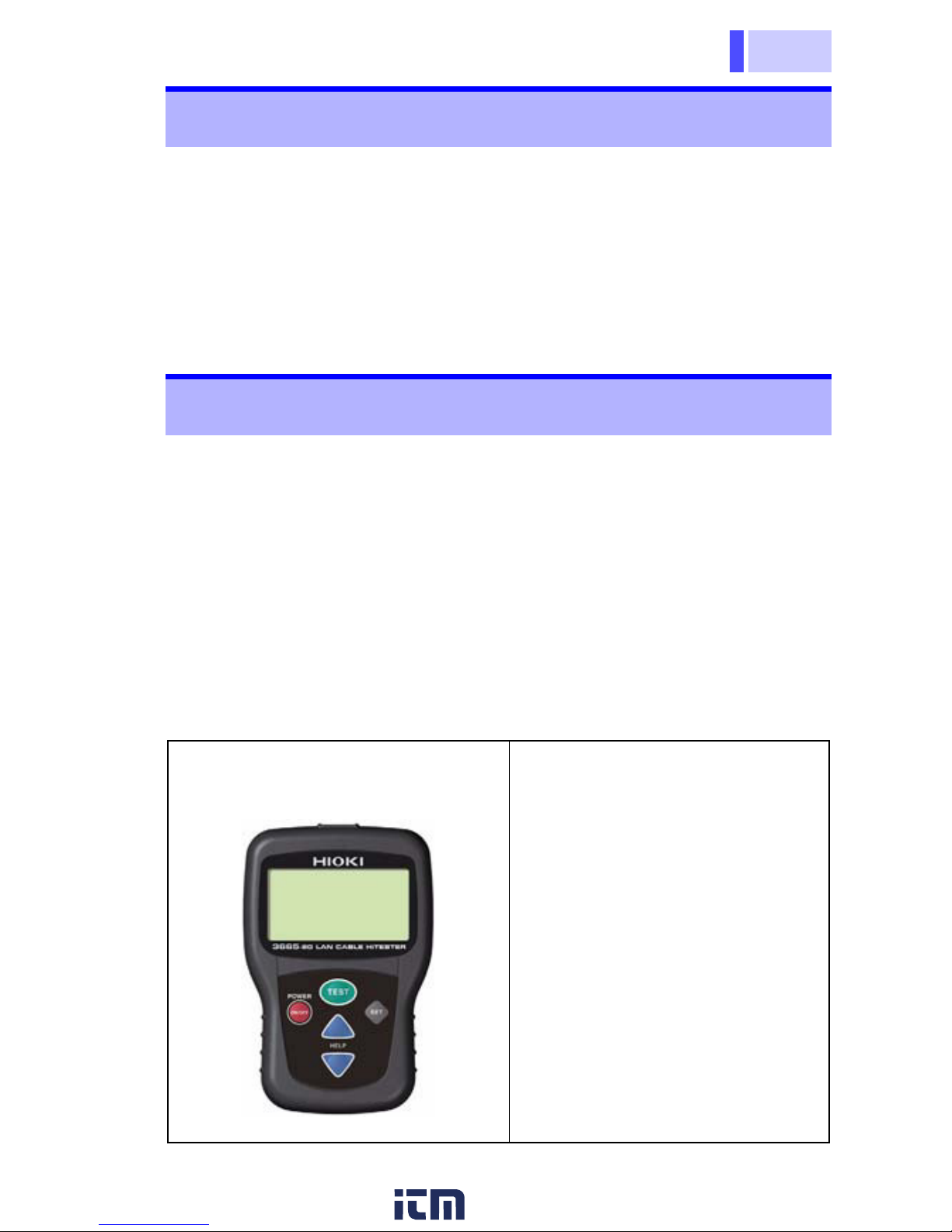
Thank you for purchasing the HIOKI “Model 3665-20 LAN
CABLE HiTESTER.” To obtain maximum performance from the
instrument, please read this manual first, and keep it handy for
future reference.
The Model 9690, 9690-01, 9690-02, 9690-03 will be referred to
as the “Model 9690” in this manual
• When you receive the instrument, inspect it carefully to ensure
that no damage occurred during shipping. In particular, check
the accessories, panel keys, and connectors. If damage is evident, or if it fails to operate according to the specifications, contact your dealer or Hioki representative.
• Use the original packing materials when transporting the
instrument, if possible.
Package Contents
Introduction
Verifying Package Contents
Model 3665-20 LAN CABLE
HiTESTER ....................... 1
Accessories
Model 9690 TERMINATOR
(ID number 0)................ 1
LR6 alkaline batteries...2
Carrying case ...............1
Instruction manual ........1
www. .c om
information@itm.com1.800.561.8187
Safety Information
2
This manual contains information and warnings essential for
safe operation of the instrument and for maintaining it in safe
operating condition. Before using it, be sure to carefully read the
following safety precautions.
Safety Information
This instrument is designed to comply with
IEC 61010 Safety Standards, and has been
thoroughly tested for safety prior to shipment. However, mishandling during use
could result in injury or death, as well as
damage to the instrument. Be certain that
you understand the instructions and precautions in the manual before use. We disclaim
any responsibility for accidents or injuries not
resulting directly from instrument defects.
Safety Symbols
In the manual, the symbol indicates particularly
important information that the user should read
before using the instrument.
Indicates DC (Direct Current).
www. .c om
information@itm.com1.800.561.8187
3
Safety Information
索引
4
7
6
5
10
9
8
The following symbols in this manual indicate the relative importance of cautions and warnings.
Indicates that incorrect operation presents a
significant hazard that could result in serious
injury or death to the user.
Indicates that incorrect operation presents a
possibility of injury to the user or damage to
the instrument.
Indicates advisory items related to performance or correct operation of the instrument.
Indicators in This Manual
Indicates a prohibited action.
( P. ) Indicates the location of reference information.
*
Indicates that descriptive information is provided
below.
www. .c om
information@itm.com1.800.561.8187
Operating Precautions
4
Before using the instrument the first time, verify that it operates
normally to ensure that the no damage occurred during storage
or shipping. If you find any damage, contact your dealer or Hioki
representative.
Operating temperature and humidity:
0 to 40
°C (32 to 104°F), 80%RH or less (non-condensating)
Accuracy guarantee for temperature and humidity:
23 ±
5°C (73 ± 9°F), 80%RH or less (non-condensating)
Operating Precautions
Preliminary Checks
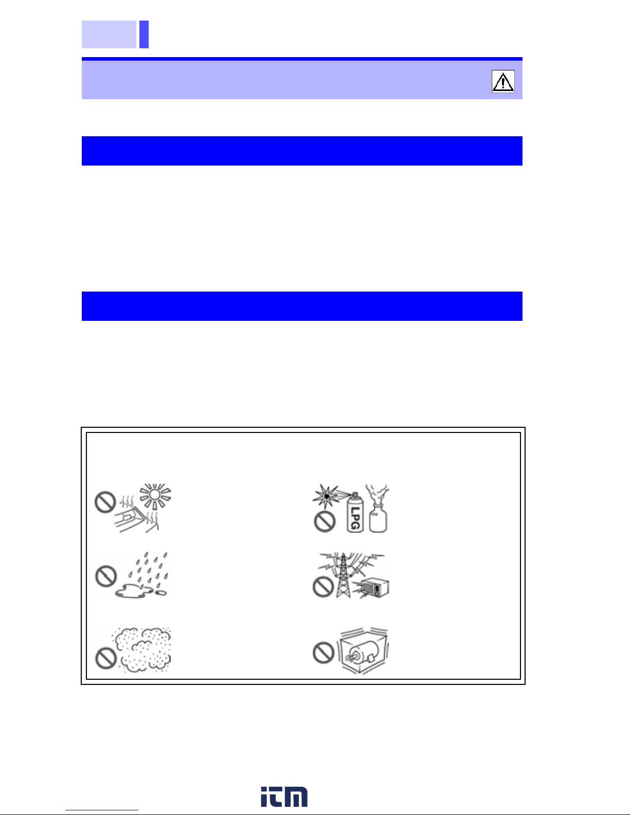
Instrument Operating Environment
Avoid the following locations that could cause an accident or
damage to the instrument.
Exposed to direct
sunlight
Exposed to high
temperature
In the presence of
corrosive or explosive gases
Exposed to liquids
Exposed to high
humidity or condensation
Exposed to strong
electromagnetic
fields
Near electromagnetic radiators
Exposed to high
levels of particulate dust
Subject to vibration
www. .c om
information@itm.com1.800.561.8187
5
Operating Precautions
索引
4
7
6
5
10
9
8
Handling the Instrument
• To avoid damage to the instrument, protect it
from physical shock when transporting and handling. Be especially careful to avoid physical
shock from dropping.
• To avoid damage to the instrument, do not
remove the instrument's case.
• To avoid damage to the instrument due to an
application of overvoltage, do not connect to live
wires such as telephone lines.
• To avoid corrosion from battery leakage and
problems with battery operation, remove the batteries from the instrument if it is to be stored for a
long time.
• The indicator flashes when battery voltage
becomes low. Replace the batteries as soon as
possible.
• After use, always turn OFF the power.
www. .c om
information@itm.com1.800.561.8187
7
1.1 Product Overview
索引
4
3
2
1
7
6
5
10
9
8
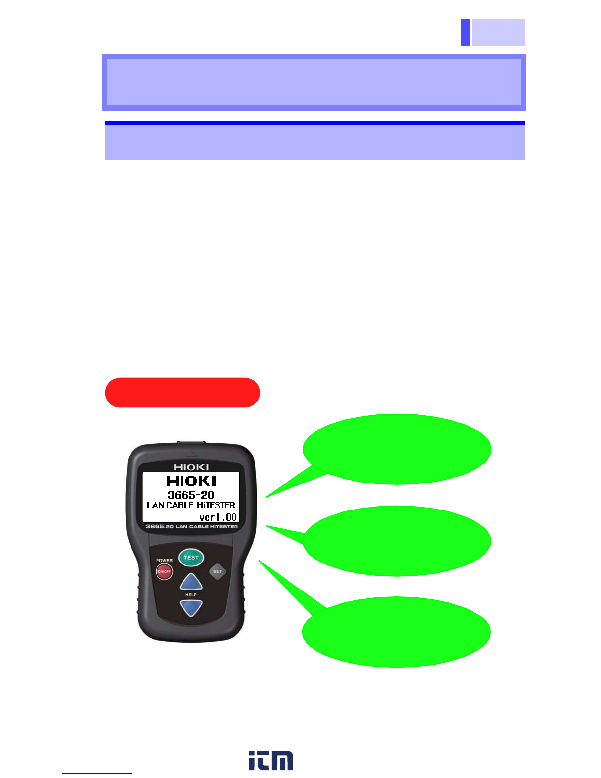
The Hioki 3665-20 LAN CABLE HiTESTER is a hand-held cable
tester that provides easy operations to test wiremap, measure
cable length and identify twisted-pair cables. It is useful for verifying connections after installing connectors on cables. Optional
terminators are available to facilitate easy identification of multiple cables. The HiTester is especially convenient for testing
cables in working networks in the event of faults caused by
open- or short-circuited cable wiring.
Overview Chapter 1
1.1 Product Overview
Test ing wirem ap
Measuring cable
length
Major Features
Identifying cable
connections
www. .c om
information@itm.com1.800.561.8187
1.1 Product Overview
8
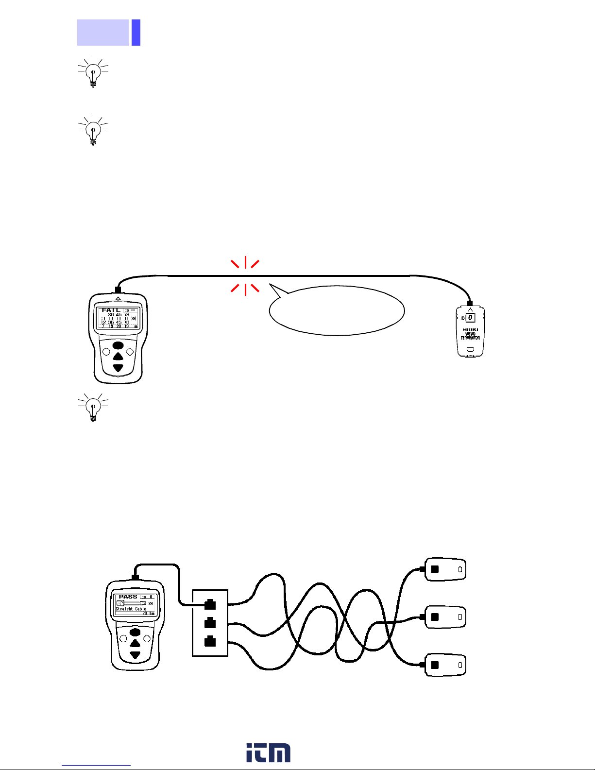
Testing cable connections after installing connectors
Checking wiremaps (p.19).
Troubleshoot cables in working networks
When an open- or short-circuit fault is present in a cable, the
HiTester displays the distance along the cable from it to the fault.
So when a problem occurs in a working network, the HiTester
determines whether the problem is caused by an open- or shortcircuit in the cable, and its location (p.29).
Identifying cables installed together
When multiple cables are installed together, distinguishing which
cable is connected to what device can be difficult. However, the
HiTester can easily identify multiple cables by using optional terminators. Up to 21 cables can be identified using multiple terminators (p.30).
Open-Circuit Wire
Detected
The figure shows an example of detecting cables through wall jacks.
Cables being checked
Model 9690 Terminators
Patch Cable
www. .c om
information@itm.com1.800.561.8187
9
1.2 Features
索引
4
3
2
1
7
6
5
10
9
8
1.2 Features
Simple Operation
Test cable wiremap, measure length and identify connections with a simple procedure: just connect the ends to the
HiTester and a terminator, and press the key.
Compact Size
The compact HiTester can be carried as a hand tool and
operated with one hand.
Easy-to-See Display
Test results are displayed in large characters and graphic
symbols.
Cable Length Measurement Calibration Function
For the most precise cable length measurements, set the
NVP value to calibrate the HiTester (p.31).
TEST
www. .c om
information@itm.com1.800.561.8187
1.3 Names and Functions of Parts
10
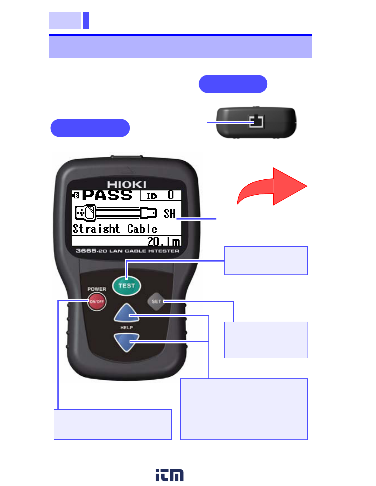
1.3 Names and Functions of Parts
Top Panel
Front Panel
(Hold for one second)
POWER ON/OFF Key
Turns the HiTester on and off.
SET Key
Displays the Settings screen
Cable Connection
Terminal (RJ-45)
HELP / Key
Switches between the Test Results and the Help screens. Also,
on the Settings screen, selects
items and increments and decrements numerical values.
TEST Key
Start cable testing
Display (LCD)
(Magnified View)
(Hold for one second)
www. .c om
information@itm.com1.800.561.8187
11
1.3 Names and Functions of Parts
索引
4
3
2
1
7
6
5
10
9
8
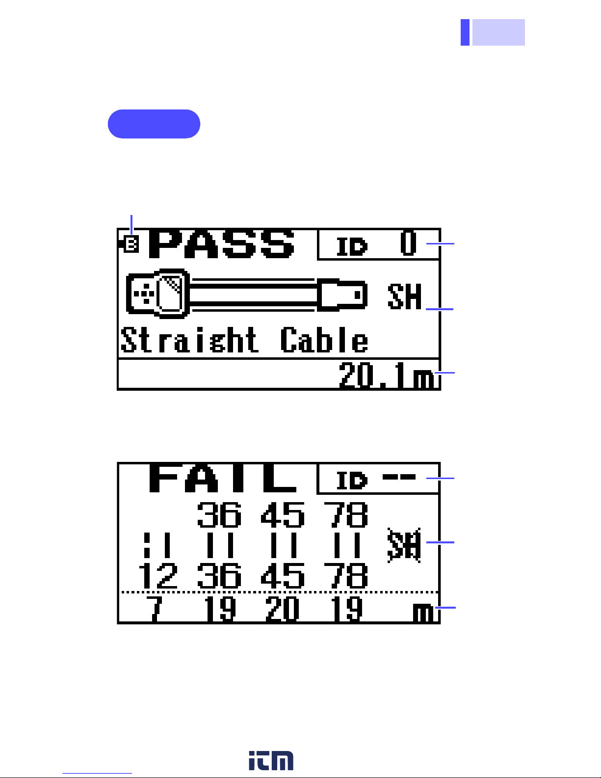
To view wiremap details, or when you want to know the meaning
of display items, press the HELP
/ key to display the Help
screen. (p.27)
Display
Display Example of Correct Wiring
Battery Indicator (normally off)
Display Example of Faulty Wiring
Cable
Length
ID
Number
ID
Number
Cable
Length
Wiring
Condition
Wiring
Condition
www. .c om
information@itm.com1.800.561.8187
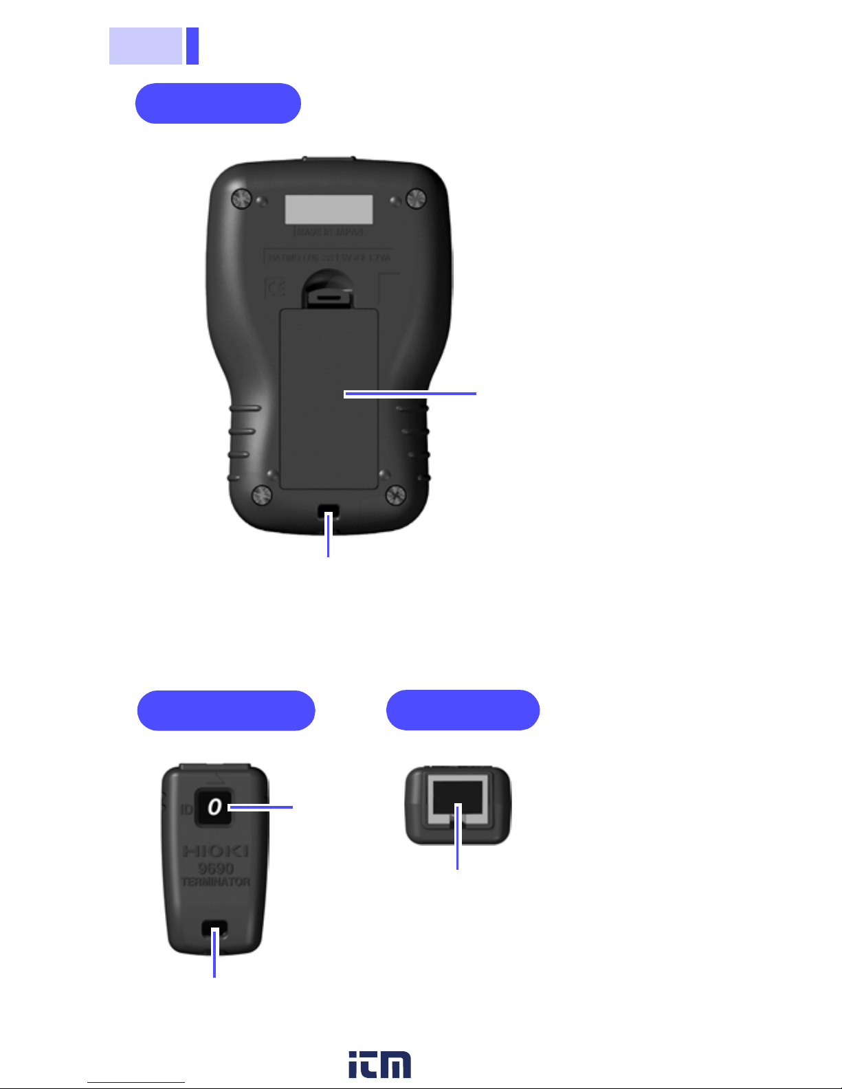
1.3 Names and Functions of Parts
12
Model 9690 TERMINATOR
Rear Panel
Battery Compartment
Cover
Strap Mounting Hole
Front Panel
Top Panel
ID
Number
Cable Connection Terminal
(RJ-45 connector)
Strap Mounting Hole
www. .c om
information@itm.com1.800.561.8187
13
2.1 Installing the Batteries
索引
4
3
2
1
7
6
5
10
9
8
Before using the HiTester, install two AA-size (LR6) alkaline batteries. Also, before each test, verify that the batteries have sufficient remaining capacity, and replace them if they are weak.
Testing
Preparations
Chapter 2
2.1 Installing the Batteries
• Do not mix old and new batteries, or different types of batteries. Also, be careful to
observe battery polarity during installation.
Otherwise, poor performance or damage
from battery leakage could result.
• To avoid the possibility of explosion, do not
short circuit, disassemble or incinerate batteries.
• Handle and dispose of batteries in accordance with local regulations.
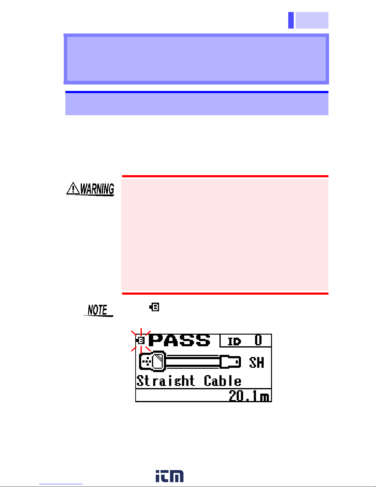
• The indicator flashes when battery voltage
becomes low. Replace the new batteries soon.
• Do not attempt to use any power source other
than the specified AA-size (LR6) alkaline batteries. Operating time with non-alkaline (manganese) batteries is shorter.
www. .c om
information@itm.com1.800.561.8187
2.1 Installing the Batteries
14
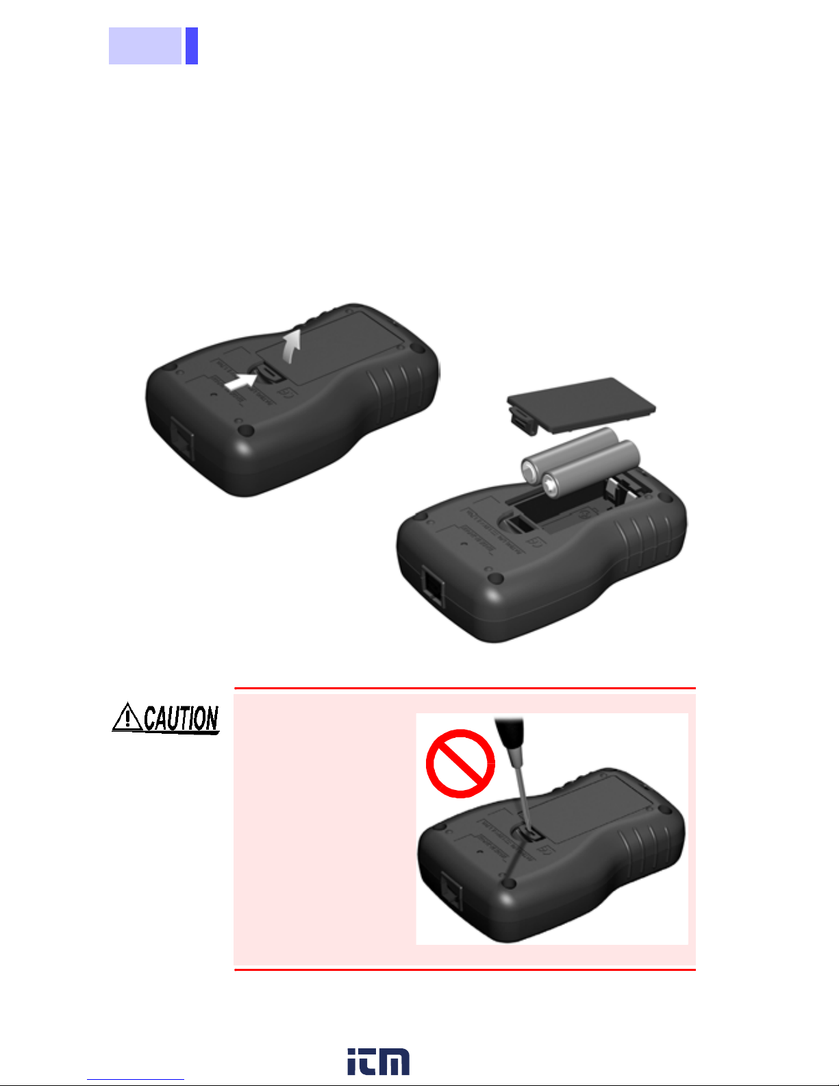
1.
Remove the test cable, if connected.
2.
Turn the HiTester off.
3.
Remove the battery compartment cover from the rear of
the HiTester.
4.
Install the new batteries, with attention to proper polarity.
5.
Replace the battery compartment cover.
Rear Panel
To avoid damaging
the battery compartment cover, do
not attempt to open
it by inserting a
screwdriver into the
latch hole.
www. .c om
information@itm.com1.800.561.8187
15
2.2 Turning the Power On and Off
索引
4
3
2
1
7
6
5
10
9
8
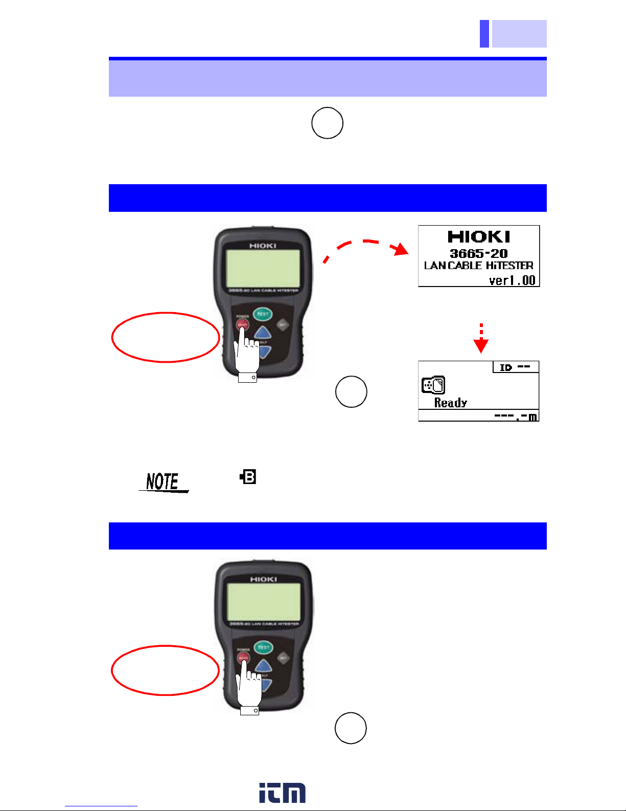
Press and hold the POWER key for about one second to
turn the power on and off.
2.2 Turning the Power On and Off
ON/OFF
Power On
Model name and
version information
To the cable test screen
Press the POWER
key to turn the power on.
ON/OFF
Hold for
one second
The indicator flashes when battery voltage
becomes low. Replace the new batteries soon.
Power Off
Hold for
one second
Press the POWER key to turn the power off.
ON/OFF
www. .c om
information@itm.com1.800.561.8187
 Loading...