

Page 1

INSTRUCTION MANUAL
3664
OPTICAL POWER METER
www. .com
information@itm.com1.800.561.8187
Page 2

X
Contents
Introduction .................................................................. 1
Inspection ..................................................................... 1
Safety Information ........................................................2
Operating Precautions .................................................4
1Overview 7
i
Contents
1
2
1.1 Product Overview ...............................................7
1.2 Features ............................................................. 8
1.3 Names and Functions of Parts ........................... 9
2 Measurement Preparations 13
2.1 Attaching the Strap ...........................................13
2.2 Supplying Power ..............................................14
2.2.1 Using the AC Adapter ........................................14
2.2.2 Using the Batteries ............................................15
2.3 Connecting the Optical Sensor .........................16
2.4 Connecting the Analog Output Cord ................17
2.5 Turning the Power On and Off ......................... 18
3 Measurement 19
3.1 Setting the Measurement Mode ....................... 20
3.2 Setting the Range .............................................21
3.2.1 Auto Range .......................................................21
3.2.2 Manual Range ...................................................22
3.3 Setting the Wavelength .................................... 24
3.3.1 Setting an Arbitrary Measurement Wa v elength .24
3.3.2 Retrieving the Wavelength Setting from t he
Measurement-Wavelength Memory ..................26
3.4 Starting Measurement ......................................26
3.5 Setting Example ............................................... 28
3.5.1 Optical-Power Measurement .............................28
3.5.2 Relative Measurement (Measured -v alue basis) 29
3.5.3 Relative Measurement (Input-value basis) ........31
3
4
5
6
7
8
9
10
11
APP
IDX
www. .com
information@itm.com1.800.561.8187
Page 3

ii
Contents
4 Functions 33
4.1 Scalling Function .............................................. 33
4.1.1 Turning ON the Scaling Function ......................33
4.1.2 Turning OFF the Scaling Function .....................36
4.2 Maximum-Value Hold / Minimum-Value Hold
/ Averaging ....................................................... 37
5 Contr ol by Comp uter 39
5.1 Overview of Control ..........................................40
5.2 Installing the Driver ...........................................41
6 Specifications 51
6.1 Measurement Specifications ............................ 51
6.2 General Specifications .....................................53
7 Maintenance and Service 55
7.1 Cleaning ........................................................... 55
7.1.1 Cleaning of the 3664 .........................................55
7.1.2 Cleaning of the Optical Sensors ........................56
7.2 Service .............................................................56
7.3 Error Display ..................................................... 57
7.4 Reset ................................................................ 59
7.4.1 System Reset ....................................................59
7.4.2 Setting Data Reset ............................................59
7.4.3 Measurement-Wavelength Memory Reset ........60
7.5 Replacing the Batteries .................................... 61
Appendix 63
Explanations .............................................................. 63
Options .......................................................................64
www. .com
information@itm.com1.800.561.8187
Page 4
Introduction
Thank you for purchasing the HIOKI “Model 3664 OPTICAL
POWER METER.” To obtain maximum performance from the
instrument, please read this manual first, and keep it handy for
future reference.
1
1
Registered Trademarks:
• Windows is a registered trademark of Microsoft Corporation in
the United States and/or other countries.
• Adobe, the Adobe logo, Acrobat, the Acrobat logo are trademarks of Adobe Systems Incorporated.
Inspection
• When you receive the instrument, inspect it carefully to ensure
that no damage occurred during shipping. In particular, check the
accessories, panel switches, and connectors. If damage is evident, or if it fails to operate according t o the specifications, contact your dealer or Hioki representative.
• Use the original packing materials when transporting the instrument, if possible.
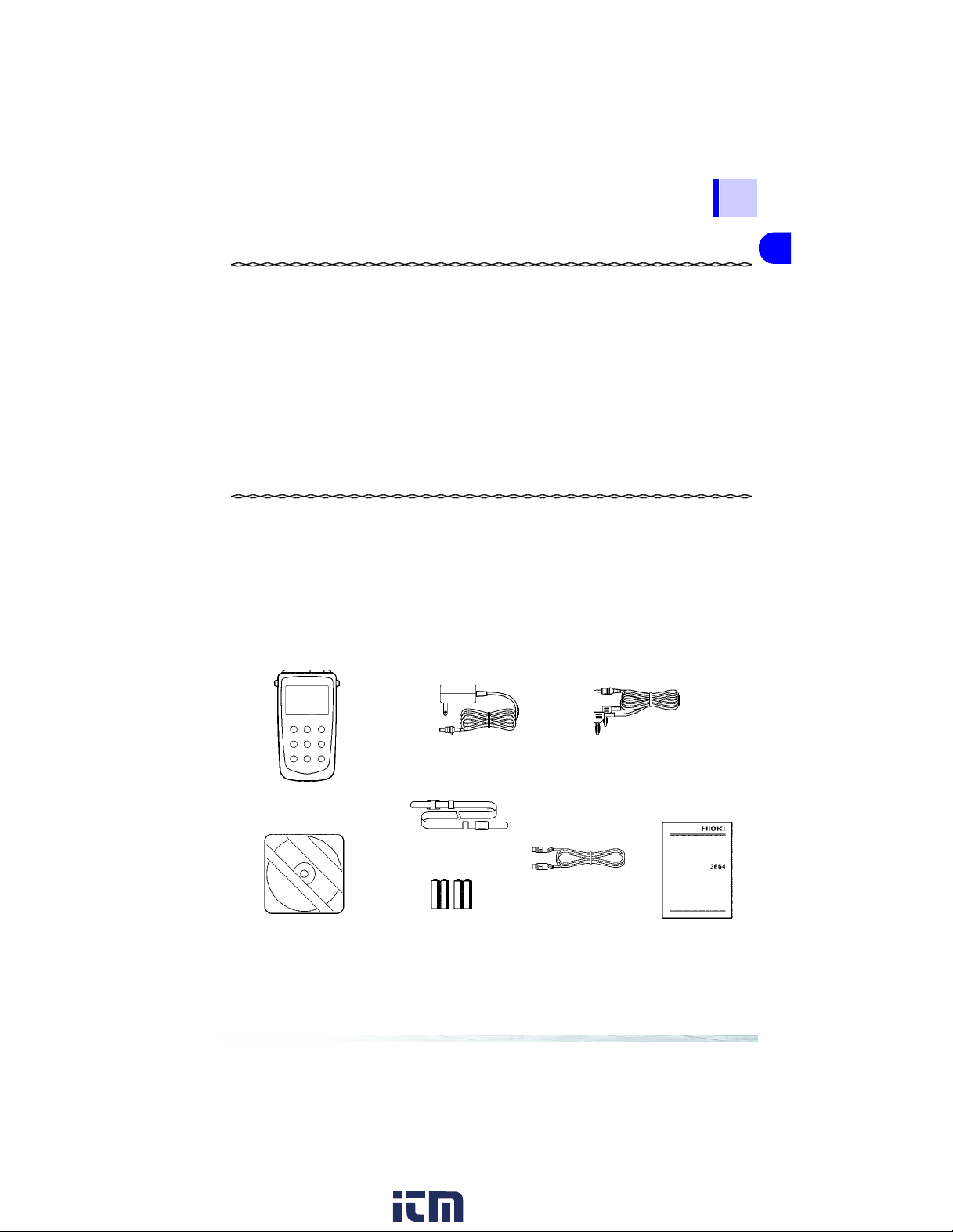
Verifying Package Contents
Model 9445-02 AC ADAPTER or
Model 9445-03 AC ADAPTER (1)
Model 3664 OPTICAL
POWER METER (1)
2
3
4
5
6
7
8
Model 9094 OUTPUT CORD (1)
9
Driver CD-R (1)
Options
Strap (1)
USB Cable (1)
LR6 alkaline batteries (4)
Model 9246 CARRYING CASE............................................... .. ...1
Model 9742 OPTICAL SENSOR..................................................1
Model 9742-10 OPTICAL SENSOR.............................................1
www. .com
Instruction Manual (1)
information@itm.com1.800.561.8187
10
11
Page 5
2
Safety Information
This instrument is designed to comply with IEC 61010 Safety
Standards, and has been tho roughly tested for safety prior
to shipment. However, mishandling during use could result
in injury or death, as well as damage to the instrument. Be
certain that you understand the instructions and precautions
in the manual before use. We disclaim an y responsibility for
accidents or injuries not resulting direct ly from instrument
defects.
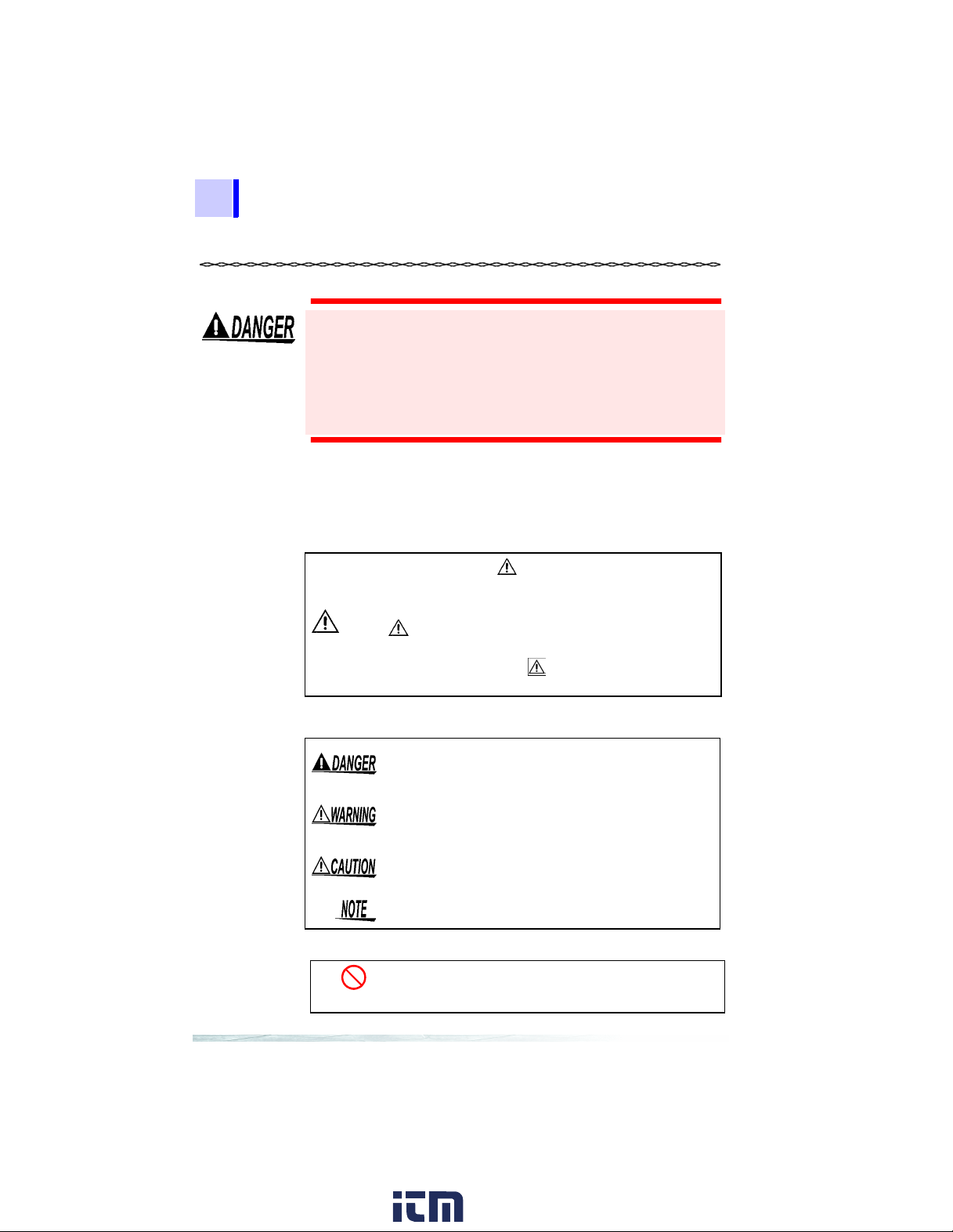
Safety Symbols
This manual contains information and warnings essential for safe
operation of the instrument and for maintaining it in safe operating
condition. Before using it, be sure to carefully read the following
safety precautions.
In the manual, the symbol indicates particularly
important information that the user should read before
using the instrument.
The symbol printed on the instrument indicates that
the user should refer to a corresponding topic in the
manual (marked with the symbol) before using the
relevant function.
The following symbols in this manual indicate the relative importance of cautions and warnings.
Indicates that incorrect operation presents an
extreme hazard that could result in serious injury or
death to the user.
Indicates that incorrect operation presents a significant hazard that could result in serious injury or
death to the user.
Indicates that incorrect operation presents a possibility of injury to the user or damage to the instru ment.
Indicates advisory items related to performance or
correct operation of the instrument.
Other Symbols
Indicates the prohibited action.
❖
Indicates the location of reference information.
www. .com
information@itm.com1.800.561.8187
Page 6
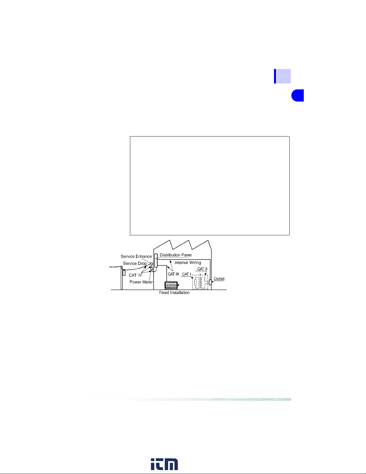
Overvoltage Categories (CAT )
To ensure safe operation of measurement instruments, IEC 60664
establishes safety standards for various electrical environments,
categorized as CAT I to CAT IV, and called overvoltage categories.
These are defined as follows.
3
1
CAT I Secondary electrical circuits connected to an AC
electrical outlet through a transformer or similar
device.
CAT II Primary electrical circuits in equipment connected to
an AC electrical outlet by a power cord (portable
tools, household appliances, etc.)
CAT III Primary electrical circuits of heavy equipment (fixed
installations) connected directly to the distribution
panel, and feeders from the distribution panel to outlets.
CAT IV The circuit from the service drop to the service
entrance, and to the power meter and primary overcurrent protection device (distribution panel).
Higher-numbered categories correspond to electrical environments
with greater momentary energy. So a measurement device
designed for CAT III environments can endure greater momentary
energy than a device designed for CAT II.
Using a measurement instrument in an environment designated
with a higher-numbered category than that for which the instrument
is rated could result in a severe accident, and must be carefully
avoided.
2
3
4
5
6
7
8
9
10
11
www. .com
information@itm.com1.800.561.8187
Page 7
4
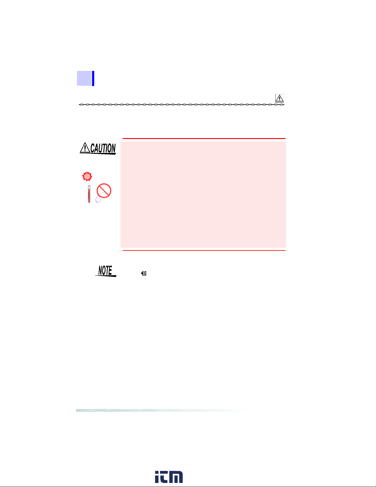
Operating Precautions
Follow these precautions to ensure safe operation and to obtain
the full benefits of the various functions.
Observe the following to avoid damage to the instrument.
• Do not allow the instrument to get wet, and do not take measurements with wet hands. This may cause an electric shock.
Avoid the following
Direct
Sunlight
High Temp erature
High Humidity
• Do not use the instrument where it may be exposed to corrosive
or combustible gases. The instrument may be damaged or
cause an explosion.
• To avoid damage to the instrument, protect it from physical
shock when transporting and handling. Be especially care ful to
avoid physical shock from dropping.
• Do not store or use the instrument wh ere it could b e exposed to
direct sunlight, high temperature or humidity, or condensation.
Under such conditions, the instrument may be damaged and
insulation may deteriorate so that it n o longer meets specifications.
• This instrument is designed for use indoors. It can be operated
at temperatures between 0 and 40°C without degrading safety.
• After use, always turn OFF the power.
• The “ ” indicator appears when batter y voltage becomes low.
Replace the batteries as soon as possible.
• Use the specified battery (AA alkaline battery) only. If a non-
specified battery such as a manganese battery is used, the
service hours may be shortened.
• When connecting the instrument to a PC with a USB cable,
use a cable of 2 m or shorter to prevent the influence of noise.
www. .com
information@itm.com1.800.561.8187
Page 8
Cords and Cables
5
• Avoid stepping on or pinching cables, which could dam age the
cable insulation.
• To avoid breaking the cables, do not bend or pull them.
• To avoid damaging the output cable, grasp the connector, not
the cable, when unplugging the cable.
Optical Sensor
• Use only the specified optical sensor. Using a non-specified sensor may result in incorrect measurements due to poor connection or other reasons.
• To prevent damage to the instrument and sensor, never connect
or disconnect a sensor while the power is on, or while the sensor
is connected around a conductor.
• To avoid damaging the optical sensor and to ensure accurate
measurements, avoid dropping or applying any p hysical shock
to the optical sensor.
• Avoid touching the detector window with your bare hands. The
detector window must be clean for the sensor to meet the specified performance parameters.
• Avoid scratching the detector window with sharp or pointed
objects (e.g., the tips of tweezers) or against hard surfaces.
Damage to the detector window may prevent the sensor from
meeting specified performance parameters.
• Make sure no stress is applied to the repeater cable of the 974210 between the sensor main unit and its detector element.
1
2
3
4
5
6
7
8
9
To prevent dust accumulation, stains, and damage, cover the
detector window with the sensor cover when the sensor is not in
use.
www. .com
information@itm.com1.800.561.8187
10
11
Page 9

6
Care and Handling of CD-R
• Always hold the disc by the edges, so as not to make fingerprints on the disc or scratch the printing.
• Never touch the recorded side of the disc. Do not place the disc
directly on anything hard.
• Do not wet the disc with volatile alcohol or water, as there is a
possibility of the label printing disappearing.
• To write on the disc label surface, use a spirit-based felt pen. Do
not use a ball-point pen or hard-tippe d pen, because there is a
danger of scratching the surface and corrupting the data. Do not
use adhesive labels.
• Do not expose the disc directly to the sun's rays, or keep it in
conditions of high temperature or humidity, as there is a danger
of warping, with consequent loss of data.
• T o remove dirt, dust, or fi ngerprints from the disc, wipe with a dry
cloth, or use a CD cleaner. Always wipe radially from the inside
to the outside, and do no wipe with circular movements. Never
use abrasives or solvent cleaners.
• Hioki shall not be held liable for any problems with a com puter
system that arises from the use of this CD-R, or for any problem
related to the purchase of a Hioki product.
Preliminary Checks
• Before using the instrument, make sure that the insulation on the
optical sensor cable and USB cable is undamaged and that no
bare conductors are improperly exposed. Using the instrument
in such conditions could cause an electric shock, so contact your
dealer or Hioki representative for repair.
• Before using the instrument the first time, verify that it ope rates
normally to ensure that the no damage occur red during storage
or shipping. If you find any damage, contact your dealer or Hioki
representative.
www. .com
information@itm.com1.800.561.8187
Page 10

1.1 Product Overview
7
Overview
1.1 Product Overview
The 3664 OPTICAL POWER METER is an instrumen t for measuring the optical power of a spatial light. It is suitable for measurement of the optical power of a laser light source and an LED light
source. The 3664 is a hand-held meter equipped with various measurement functions and interfaces that meet diversified measurement needs. The optical sensors (optional) for the power meter are
interchangeable, as the sensitivity of each sensor is adjusted independently.
1
1
2
3
4
5
6
7
8
www. .com
9
10
11
information@itm.com1.800.561.8187
Page 11

8
1.2 Features
1.2 Features
Scaling function
The reading of the 3664 OPTICAL POWER METER can be converted to the reading of another optical power meter by a simple
operation.
Various measurement functions
In addition to the optical power measurement (absolute-value measurement), the 3664 power meter has relative-measurement, maximum-value-hold, minimum-value-hold, and averaging functions.
With all these functions, the display unit can be switched between
W and dBm (dB).
Automatic correction of sensitivity through input of
the measurement wavelength
When the measurement wavelength is entered, the wavelength
sensitivity of the sensor connected to the 3664 is automatically corrected for measurement display.
Interface with a computer
The USB interface is provided as standard equipment. The 3664
can be controlled on the PC, its settings can be edited on the PC ,
or its measurement data can be uploaded to the PC.
Analog output terminal
The 3664 has an analog output terminal. It outputs in the voltage
form the output signal of the optical sensor. Use this terminal, for
example, when performing monitoring using a DMM or reco rding
data for extended periods.
Auto-power-save funct ion
When the 3664 is running on the battery, if there is no key operation or USB communication for approximately 10 minutes, the
power to the 3664 will be automatically turned off to conserve battery power.
www. .com
information@itm.com1.800.561.8187
Page 12
1.3 Names and Functions of Parts
1.3 Names and Functions of Parts
9
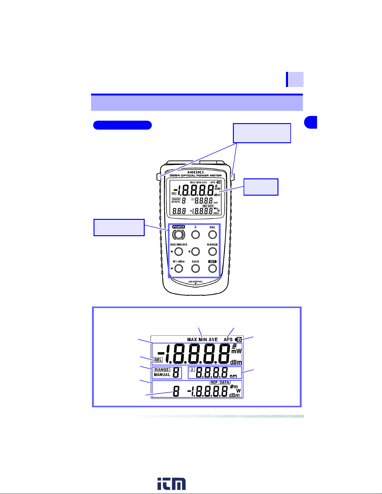
Front Panel
Operating Keys
Strap installation
Slot
Display
1
2
3
4
5
6
7
8
Display
Main display
Relative-measurement
indicator
Range
Sub display
Relative-measurement
mode
www. .com
Maximum, Minimum, Ave ra ge
Auto power save mark
Battery mark
Measurement
wavelength
information@itm.com1.800.561.8187
9
10
11
Page 13

10
1.3 Names and Functions of Parts
Operating Keys
POWER
λ
REL
RANGE
SET
SAVE
W/dBm
▼
MAX/MIN/AVE
▲
Turns ON/OFF power to the 3664.
Power ON: Hold down the key for approximately 2 seconds to
Power OFF: Hold down the key for approximate ly 1 second to turn
Sets the measurement wavelength to the preset wavelength.
Switches between optical-power measurement mode, relative-
measurement mode (measured-value basis) and relative-measurement mode (input-value basis).
Switches between auto range and manual range.
Moves to the setting edit screen. "
Moves the digit to edit the setting (the digit blinks) during setting
edit.
Confirms the setting during setting edit and returns the meter to
measurement mode.
Switches the unit of the reading between "W" and "dBm." In rela-
tive-measurement mode, the unit is switched between "W" and
"dB."
Decreases the number during setting edit.
Switches the value to be displayed between the measurement,
maximum, minimum, and average value.
Increases the number during setting edit.
turn the power ON (auto-power-save function ON).
Hold down the key for approximately 5 seconds to
turn the power ON and the auto-power-save function
is turned OFF.
the power OFF.
" appears on the screen.
SEt
www. .com
information@itm.com1.800.561.8187
Page 14
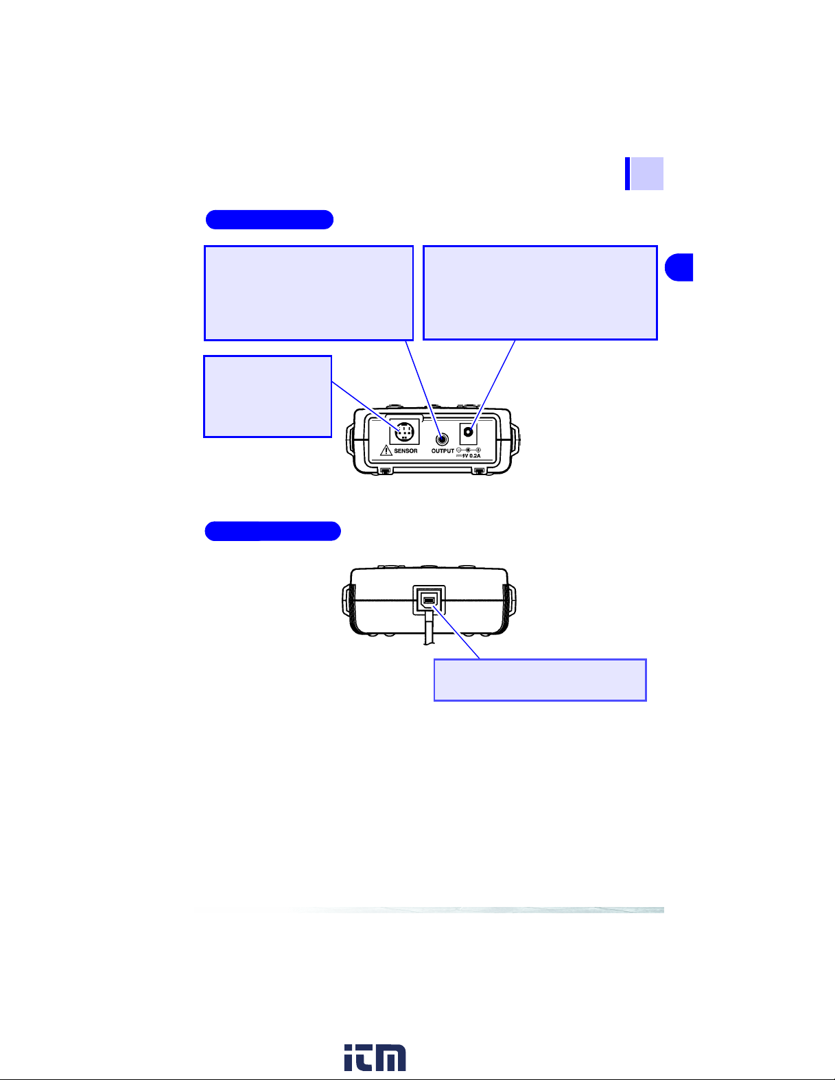
Upper Panel
11
1.3 Names and Functions of Parts
Analog output terminal
Connect the 9094 OUTPUT CORD included among the accessories to this
terminal. Output signals from the optical sensor are converted to a voltage
and output from this terminal.
Optical-sensor
terminal
Connect an optional
optical sensor to this
terminal.
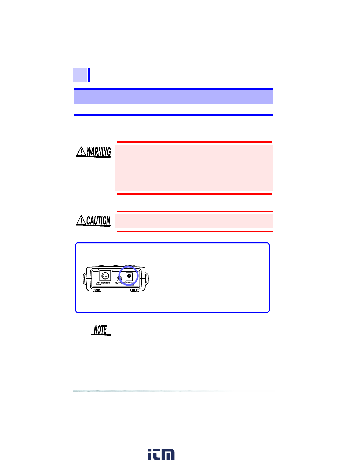
Bottom Panel
AC-adapter terminal
Connect the 9445-02 or 9445-03 AC
ADAPTER included among the accessories to this terminal. When the AC adapter
is used, power is supplied to the 3664 from
a commercial power supply.
1
2
3
4
5
6
7
8
www. .com
USB terminal
Connect a USB cable to this terminal.
information@itm.com1.800.561.8187
9
10
11
Page 15
2.1 Attaching the Strap
13
Measurement Preparations
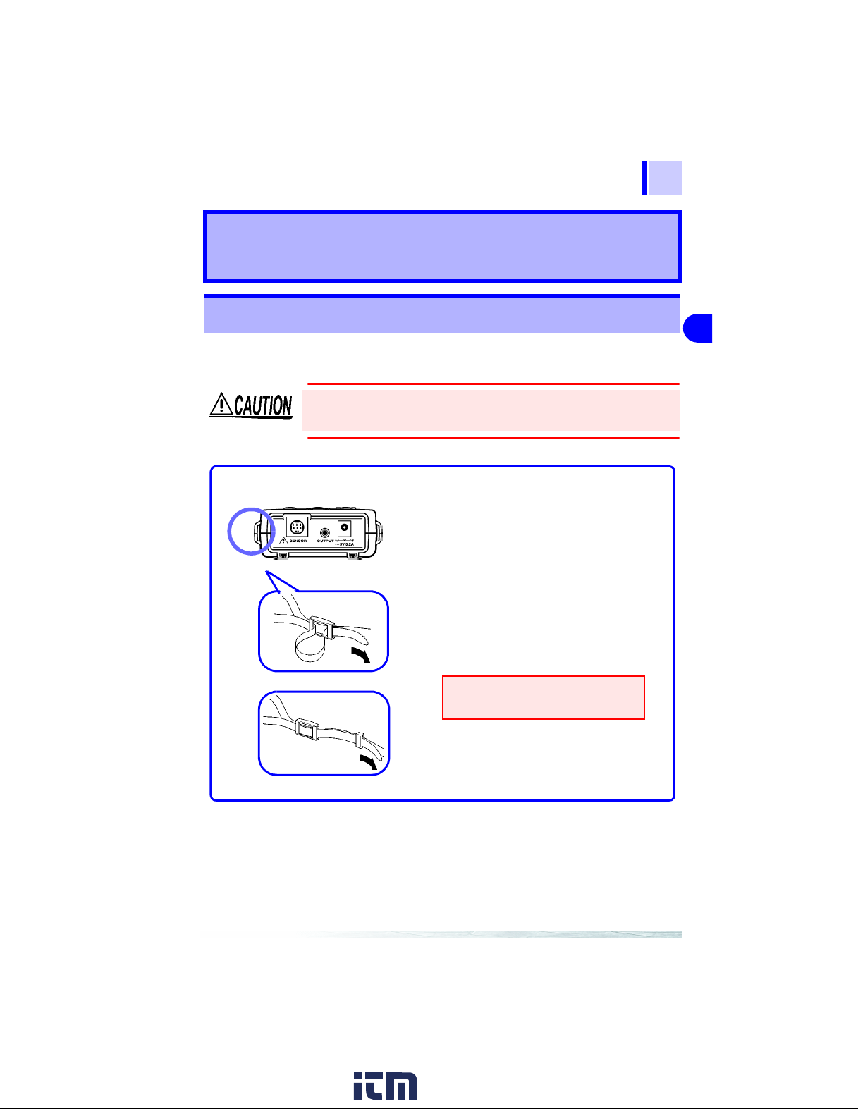
2.1 Attaching the Strap
Use the strap to carry the 3664 power meter or hang it on a hook.
Be sure to attach the strap to the 3664 power meter in place (2 locations) properly . If the strap is not properly attached, the meter m ay drop
and be broken.
Model 3664
Insert each end of the Strap through
1.
an installation slot on the instrument.
Feed each end of the Strap through its
2.
clasp.
Feed each end through its stopper.
3.
2
1
2
3
4
5
6
7
8
Confirm that the strap is not
slackened or twisted.
www. .com
9
10
information@itm.com1.800.561.8187
Page 16
14
2.2 Supplying Power
2.2 Supplying Power
2.2.1 Using the AC Adapter
• Use only the specified Model 9445-02 ADAPTER (SA109010N,SINO-AMERICAN) or Model 9445-03 AC ADAPTER
(CEE, SA10-9010G, SINO-AMERICAN) AC adapter input
voltage range is 100 to 240 VAC (with ±10% stability) at 50/
60 Hz. To avoid electrical hazards and damage to the instrument, do not apply voltage outside of this range.
• Turn the instrument off before connecting the AC adap ter
to the instrument and to AC power.
To avoid damaging the cord, grasp the plug, not the cord, when unplugging it.
AC Adapter Connection Term i na l
• When the AC adapter is connected and the battery is installed,
the AC adapter is used. In case of power outage, the 3664 is
automatically switched to the battery drive.
• Make sure the power is turned off before connecting or discon-
necting the AC adapter.
Connect the output plug of the AC
1.
adapter to the AC-adapter terminal.
Connect the AC adapter to an AC
2.
outlet.
www. .com
information@itm.com1.800.561.8187
Page 17
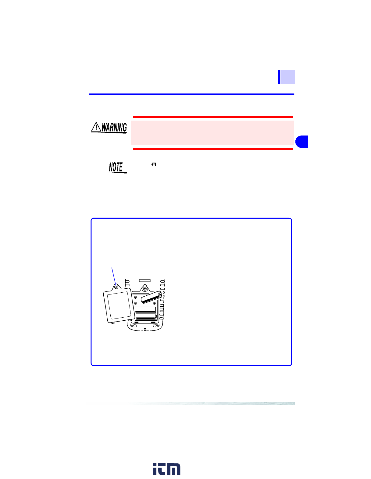
2.2.2 U sing the Batteri es
15
2.2 Supplying Power
Screw
Do not mix old and new batteries, or different types of batteries. Also, be careful to observe ba ttery polarity during installation. Otherwise, poor performance or da mage from battery
leakage could result.
• The “ ” indicator appears when battery voltage becomes low.
Replace the batteries as soon as possible.
• Do not use other than the specified type of batteries (LR6 alkaline batteries). Using manganese batteries will result in a
shorter operating time than when using alkaline batteries.
• The 3664 power meter runs on battery or AC power. When the
AC adapter is connected and the battery is installed, the AC
adapter is used.
Tools and materials:
Four AA alkaline batteries (LR6) and a Phillips screwdriver
Confirm that the power to the 3664 is
1.
turned OFF.
Disconnect all cables.
2.
Turn over the 3664 and loosen the
3.
screw on the battery cover.
1
2
3
4
5
6
7
8
Remove th e ba t te r y cover.
4.
Insert the four AA alkaline batteries
5.
(LR6) into the battery case, noting the
correct polarity. (When replacing the
batteries, replace all of them.)
Place the battery cover back on, and
6.
tighten the screw.
www. .com
9
10
information@itm.com1.800.561.8187
Page 18
16
2.3 Connecting the Optical Sensor
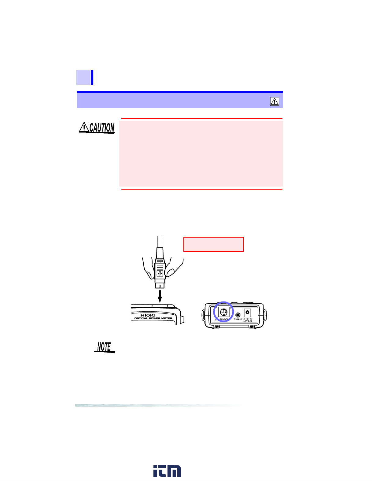
2.3 Connecting the Optical Sensor
• Use only the specified optical sensor. Using a non-specified sensor may result in incorrect measurements due to poor connection or other reasons.
• To prevent damage to the instrument and sensor, never connect
or disconnect a sensor while the power is on, or while the sensor
is connected around a conductor.
• To avoid damaging the sensor cable, grasp the plug, not the
cable, when unplugging it.
• To avoid ensuring accurate measurements, avoid dropping or
applying any physical shock to the optical sensor.
Insert an optical sensor, with the surface marked with an arrow facing upward, into the optical-sensor terminal of the 3664.
Optical Sensor
Grasp the connector.
Optical Sensor Connection Te rmi na l
Always grasp the connector with the arrow to connect or disconnect the optical sensor. (You must grasp the connector to disconnect the sensor.)
www. .com
information@itm.com1.800.561.8187
Page 19
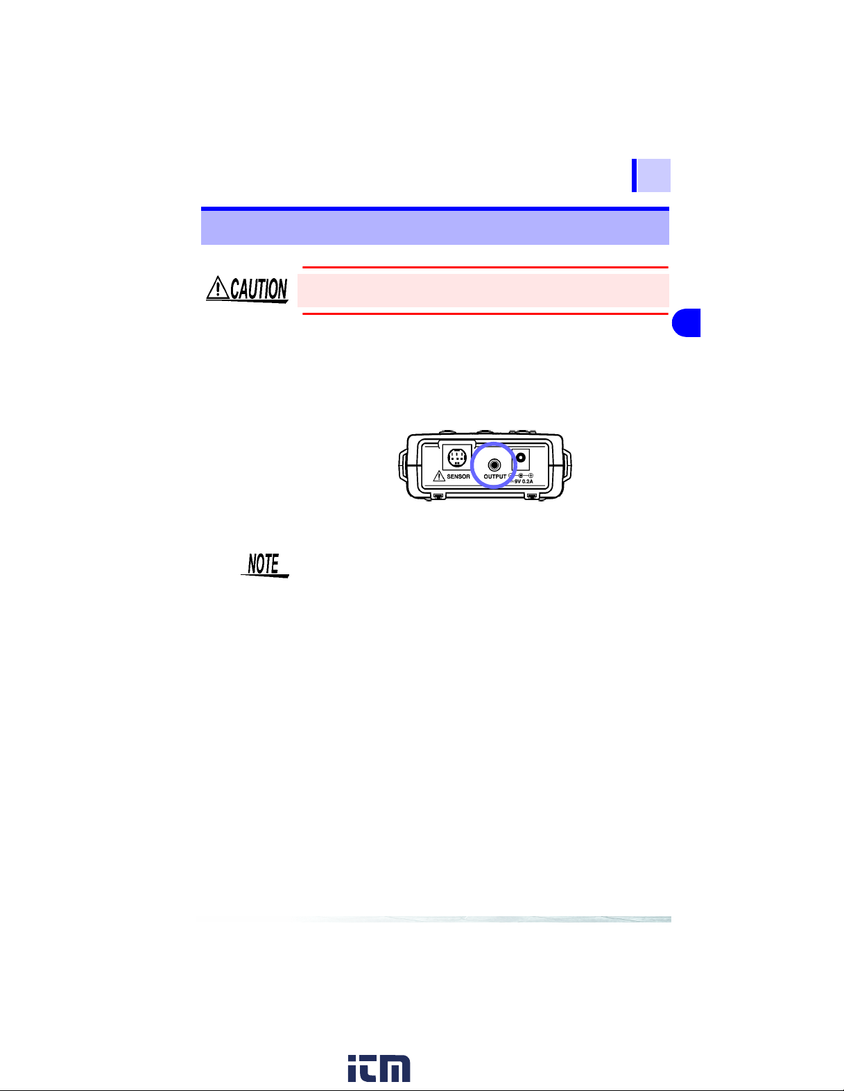
2.4 Connecting the Analog Output Cord
2.4 Connecting the An alog Output Cord
17
To avoid damage to the instrument, do not short-circuit the o utput terminal and do not input voltage to the output terminal.
By connecting the analog output cord to the analog output terminal,
the optical power detected by the optical sensor can be converted
to a voltage in order to monitor the signal.
Connect the analog output cord to the analog output terminal.
Analog Output Cord
Signals output from the analog output terminal are detected by
an optical sensor, with its wavelength sensitivity uncorrected.
This signal, therefore, is not proportional to the measurement
displayed on the screen.
1
2
3
4
5
6
7
8
www. .com
9
10
information@itm.com1.800.561.8187
Page 20
18
2.5 Turning the Power On and Off
2.5 Turn in g the Power On and Off
Power On
Hold down the POWER key for approximately 2 seconds. The
screen lights up and the power is turned ON.
If the battery indicator appears (" " at the top right of the
screen) after the power has been turned ON, the battery is running down. Replace the battery (when the 3664 is running on the
battery).
❖See Section 7.5 "Replacing the Batteries" (61 page)
Power OFF
Hold down the POWER key for approximately 1 second. The
screen goes out and the power is turned OFF.
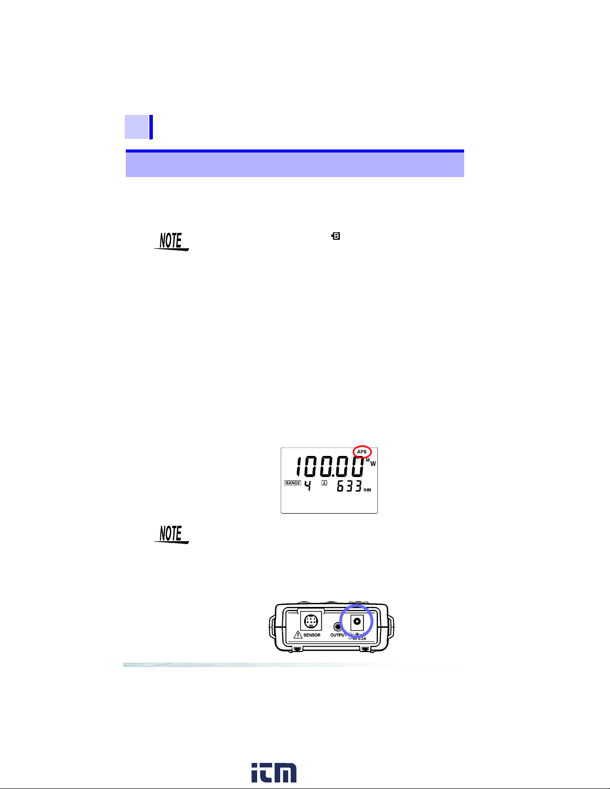
Auto-power-save funct ion
• This function automatically turns OFF the power to the 3664 if
there is no key operation or USB communication for approximately 10 minutes, when it is running on the battery. (The indication "
• To turn OFF the auto-power-save function, hold down the
POWER key for 5 seconds when turning ON the power. "
goes out and the auto-power-save function is turned OFF.
• When the 3664 is running on AC power, the auto-power-save
function is automatically turned OFF and the function is not available.
" lights up at the top right of the screen.)
APS
APS
"
• While power is supplied from the battery, when the power is
turned ON, the auto-power-save function is turned ON.
• When the USB is used, use the AC adapter for the power supply.
• After use, always turn OFF the power.
AC Adapter Connection Terminal
www. .com
information@itm.com1.800.561.8187
Page 21

19
Measurement
• Optical-power measurement and relative measurement of special light are performed using the 3664 power meter.
• The measurement wavelength may be set to an arbitrary wavelength.
• The measurement wavelength may also be set to a previously
set wavelength.
Connect an optional optical sensor to the 3664. To operate the
3664, an optical sensor must be connected to it.
Flow of measurement
Setting of the measurement
Setting of the range
Setting of the measurement wavelength
❖(2 0 page)
❖(21 page)
(24 page)
❖
3
1
2
3
4
5
6
7
8
Input of light to the sensor
❖(2 6 page)
9
10
www. .com
information@itm.com1.800.561.8187
Page 22

20
3.1 Setting the Measurement Mode
3.1 Setting the Measurement Mode
Each time the
changes as shown below.
Optical-power measurement
Relative measurement (measured-value basis)
Relative measurement (input-value basis)
key is pressed, the measurement mode
REL
The 3664 performs optical- po w er measurement.
The 3664 sets th e optical p ower
of the incident light to the optical
sensor as the reference value,
and measures th e difference between the set reference va lue
and the current incident o ptical
power.
The 3664 measures the difference between the refe re nce v alue arbitrarily set by key entry
and the current incident optical
power.
www. .com
information@itm.com1.800.561.8187
Page 23

3.2 Setting the Range
21
3.2 Setting the Range
Each time the
range alternate.
3.2.1 Auto Range
The appropriate range for the incident optical power is automatically selected. The range display area will appear as shown below.
RANGE
Auto Range
key is pressed, auto range and manual
Manual Range
1
2
3
4
5
6
7
8
When the RANGE key is pressed, "MANUAL" appears in the range
display area and the range is fixed to that displayed.
www. .com
information@itm.com1.800.561.8187
9
10
Page 24

22
3.2 Setting the Range
3.2.2 Manual Range
The range is set manually. "
area.
1.
Press the
2.
Press the
the manual range. The range display area will blink.
key to display the setting edit screen.
SET
RANGE
MANUAL
key to display the setting edit screen for
" appears in the range display
Blinking
3.
Use the ▲ and ▼ keys to change the range s et t ing.
▲
: Increases the sensitivit y range by one increment
▼
: Decreases the sensiti vity range by one increment
The range No. displayed on the screen is the range No. of the internal
circuit. The range is divided into seven levels, from 1 (lowest
sensitivity) to 7 (highest sensitivity).
www. .com
information@itm.com1.800.561.8187
Page 25

3.2 Setting the Range
4.
Press the
the 3664 will return to the meas urement scree n. The range
is now fixed.
key to save the setting. "
SAVE
" is displayed;
SAVE
23
1
2
3
4
Fixed range
When the range is fixed through manual range setting, the measurement display shows "
below the measurement range, and it shows "Hi" if the power
exceeds the range.
"Lo" Display
" if the incident optical power falls
Lo
"Hi" Display
5
6
7
8
9
10
www. .com
information@itm.com1.800.561.8187
Page 26

24
3.3 Setting the Wavelength
3.3 Setting the Wavelength
The following two methods can be used:
• Set an arbitrary measurement wavelength.
• Retrieve a wavelength from the measurement-wavelength memory, and set it as the measurement wavelength.
• The selectable wavelength range depends on the specification
of the optical sensor connected to the 3664.
• To ensure proper measurement, set the wavelength to the
wavelength of the light used.
3.3.1 Setting an Arbitrary Measurement Wavelength
1.
Press the
key to display the setting edit screen.
SET
2.
Press the λ key to display the setting edit screen for the
measurement wavelength.
Blinking
3.
Use the ▲ and ▼ keys to change the measurement wavelength.
▲
: Increases the number
▼
: Decreases the numbe r
www. .com
information@itm.com1.800.561.8187
Page 27

3.3 Setting the Wavelength
4.
Press the key to change the blinking digit.
Blinking
Repeat steps 3 and 4 above to set t he measurement w av elength.
5.
Press the
"SAVE" appears; the 3664 will then return to the measurement
screen. The measurement wavelength is now set.
key to complete setting.
SAVE
The measurement waveleng th set
25
1
2
3
4
5
6
• An arbitrarily set measurement wavelength is automatically
saved in the measurement-wavelength memory.
• The measurement-wavelength memory holds up to 10 wavelengths (including preset wavelengths for each optical sensor).
• Each optical sensor has preset wavelengths. These preset
wavelengths cannot be edited.
• Through the setting operation for the arbitrary measurement
wavelength, the setting data is automatically saved in the measurement-wavelength memory. When it is necessary to save a
new measurement wavelength to the measurement-wavelength memory when the memory already contains 10 wavelengths, the oldest data is deleted in order to make space for
the new data.
• To reset the data in the measurement-wavelength memory,
perform measurement-wavelength-memory reset. This will
return the memory to its default state for each sensor.
❖See Section 7.4.3 "Measurement-Wavelength Memory Reset" (60
page)
7
8
9
10
www. .com
information@itm.com1.800.561.8187
Page 28

26
3.4 Starting Measurement
3.3.2 Retrieving the Wavelength Setting from the Measurement-Wavelength Memory
Each time the λ key is pressed, the measurement wavelengths
stored in the memory are retrieved individually in order.
To reset the data in the measurement-wavelength memory, perform measurement-wavelength-memory reset. This will return
the memory to its default state for each sensor.
❖See Section 7.4.3 "Measurement-Wavelength Memory Reset" (60 page)
3.4 Starting Measurement
1.
When using the 9742 OPTICAL
Model 9742 OPTICAL SENSOR
Optical Sensor
Cover
SENSOR, slide the sensor cover
of the optical sensor until it clic ks
to lock the cover. When using the
9742-10 OPTICAL SENSOR,
remove the optical-sensor cover.
Model 9742-10 OPTICAL SENSOR
Optical Sensor
Cover
• Removed sensor cover (B e
• Mount the sensor cover as
careful to avoid misplacing.)
shown in the figure to the
left.
When using the 9742-10 OPTICAL SENSOR, remove the cover
of the optical sensor.
2.
Inject light.
3.
The 3664 displays the measured
optical power.
www. .com
information@itm.com1.800.561.8187
Page 29

27
3.4 Starting Measurement
• To ensure accurate measurements, make sure the detector
window is free of dust, stains, and any damage.
• Confirm that the light to be measured fits completely within the
detector window.
• If the optical power is too intense for the unit area, such as
when a condensed beam on the focus plane is measured, the
optical sensor may be saturated and the 3664 may not be able
to conduct accurate measurement. This problem can be
solved by changing the distance between the light source and
the detector window of the optical sensor.
• The operation of the light source may become unstable due to
the reflection of light from the detector window of the optical
sensor. This problem can be solved by angling the detector
window slightly to prevent the reflection from ret urning to the
light source.
• If background light, sunlight, illumination light, or any other light
than the light to be measured is overly intense, the 3664 may
not be able to conduct accurate measurement. Take appropriate light-shielding measures.
1
2
3
4
5
6
7
8
9
10
www. .com
information@itm.com1.800.561.8187
Page 30

28
3.5 Setting Example
3.5 Setting Example
3.5.1 Optical-Power Measurement
The 3664 performs optical-power measurement.
(1) Set the measurement mode.
Press the
(2) Set the measurement wavelength.
Set the measurement wavelength to an arbitrary wavelength or
one retrieved from the memory. The sensitivity is corrected by the
set measurement wavelength, and the 3664 displays the measured value adjusted in accordance with the corrected sensitivity.
Set the measurement wavelength to the wavelength of the light
used. If the wavelengths differ, the 3664 is not able to conduct
accurate measurement.
key to select the optical-power measurement mode.
REL
Optical-power
measurement
www. .com
information@itm.com1.800.561.8187
Page 31

3.5 Setting Example
3.5.2 R ela tive Mea surem ent (Meas ur ed-va lue basi s)
29
(1) Set the measurement mode.
(2) Set the measurement wavelength.
(3) Loading the reference value/relative measurement (when the optional
Model 9742 OPTICAL SENSOR
Model 9742-10 OPTICAL SENSOR
The 3664 sets the optical power of the incident light to the optical
sensor as the reference value, and measures the difference
between the set reference value and the current incident optical
power.
Press the
value basis) mode.
Set the measurement wavelength to an arbitrary wavelength or
one retrieved from the memory.
Set the measurement wavelength to the wavelength of the light
used. If the wavelengths differ, the 3664 is not able to conduct
accurate measurement.
9742 or 9742-10 OPTICAL SENSOR is used)
Optical Sensor
Cover
• Removed sensor cove r (Be
careful to avoid misplacing.)
• Mount the sensor cover as
shown in the figure to the
left.
key to select the relative-measurement (measured-
REL
1.
When using the 9742 OPTICAL
SENSOR, slide the sensor cover
of the optical sensor until it clicks
to lock the cover. When usi ng the
Optical Sensor
Cover
9742-10 OPTICAL SENSOR,
remove the optical-sensor cover.
When using the 97 42-10 OPTICAL
SENSOR, remove the cover of the
optical sensor.
2.
Inject light.
3.
In the relative-measure ment (measured-value basis) mode, hold
down the
mately 3 seconds.
key for approxi-
SAVE
1
2
3
4
5
6
7
8
9
10
www. .com
information@itm.com1.800.561.8187
Page 32

30
3.5 Setting Example
4.
"
" is displayed on the screen, and the relative-mea-
SAVE
surement result is then displayed.
The result is save d as the optical-pow er measuremen t reference valu e.
Mode
5.
"0" appears on the left side of t he sub-dis play are a, indicat -
Reference Value
ing the relative-measurement (measured-value basis)
mode, and the saved reference value is displayed on the
right side of the sub-display area.
The main display area shows the relative-measurement
value.
In the relative-mea surem ent (me asur ed- value basis ) mo de,
the value show n below is displayed.
(Current measurement) - (measurement set as the reference value)
• Only one reference value is saved, regardless of the wavelength setting. When a different measurement wavelength is
used, set a new reference value.
• When the maximum-value-hold, minimum-value-hold, or a veraging function is ON, "(calculation result) - (reference value)" is
displayed.
• When the scaling function is ON, "(value af ter scaling) - (refe rence value)" is displayed.
• When the reference value is input, if the main display area
shows "
The relative measurement is not calculated, and "
played on the screen.
" or "Hi," Lo or Hi is saved as the reference value.
Lo
- - - -
" is dis-
www. .com
information@itm.com1.800.561.8187
Page 33

3.5 Setting Example
3.5.3 Relative Measurement (Input-value basis)
31
The 3664 measures the difference between the reference value
arbitrarily set by key entry and the current incident optical power.
Entering the Reference Value Using the Keys/Relative
Measurement
1.
Press the
2.
Press the
screen.
3.
Use the ▲ and ▼ keys to change the position of the decimal
point and the unit.
▲
: Increases the number
▼
: Decreases the number
key to display the setting ed it screen.
SET
key to display the reference-value input
REL
Blinking
Blinking
1
2
3
4
5
6
7
8
9
4.
Press the key to change the blinking digit.
www. .com
information@itm.com1.800.561.8187
10
Blinking
Page 34

32
3.5 Setting Example
5.
Use the ▲ and ▼ keys to change the blink ing number.
▲
: Increases the number
▼
: Decreases the numbe r
Repeat steps 4 and 5 ab ov e t o s et the r ef erence value.
6.
Press the
"
" appears and then the 3664 returns to the measure -
SAVE
ment screen. The mea surem ent wa velen gth i s now se t an d
the relative-measurem ent result is dis played.
key to comp l ete setting.
SAVE
Blinking
Mode
The number "1" appears on the left side of the sub-display area,
indicating the relative-measurement (input-value basis) mode, and
the saved reference value is displayed on the right side of the subdisplay area.
The main display area displays the relative-measurement value.
In the relative-measurement (input-value basis) mode, the value
shown below is displayed.
(Current measurement) - (value entered using th e keys as the reference value)
• Only one reference value is saved regardless of the wavelength setting.
• When a different measurement wavelength is used, set a new
reference value.
• The values that can be entered using the keys as the reference
value range from 0.001 nW to 1.9999 W (-90.00 dBm to 33.0
dBm).
• When the maximum-value-hold, minimum-value-hold, or a veraging functions is ON, "(calculation result) - (reference value)"
is displayed.
• When the scaling function is ON, "(value af ter scaling) - (refe rence value)" is displayed.
Reference Value
www. .com
information@itm.com1.800.561.8187
Page 35

4.1 Scalling Function
33
Functions
• Using the scaling function, a measured value can be converted
to an arbitrary value and the converted value displayed.
• The maximum-value-hold, minimum-value-hold, and averaging
functions are available.
4.1 Scalling Function
• A measured value is converted by scaling to an arbitrary value
and displayed. When the scaling function is turned ON, "(measured value) x (internal coefficient)" is displayed.
• The internal scaling coefficient for each wavelength is saved in
the memory.
• When the display value after scaling is set, the internal coe fficient is automatically calculated and saved.
4.1.1 Turning ON the Scaling Function
Save the internal scaling coefficient, and turn ON the scaling function.
1.
Input the light to be measu red to the optical sensor.
2.
Press the
key to display the setting ed it screen.
SET
4
1
2
3
4
5
6
7
8
www. .com
9
10
information@itm.com1.800.561.8187
Page 36

34
4.1 Scalling Function
3.
Press the λ key to display the setting edit screen for the
measurement wavelength.
Blinking
Scaling function
The value displaye d first in the sub-displa y area is the display value with the scaling OFF (internal coefficient of
1.000).
4.
Use the key to move the cursor to a digit in the s ub-display area.
5.
Use the ▲ and ▼ keys to change the blink ing number.
▲
: Increases the number
▼
: Decreases the numbe r
Repeat steps 4 and 5 above to set the display value after
scaling.
Measured value immediately before
the setting edit screen appears
Blinking
Sub Display
Blinking
www. .com
information@itm.com1.800.561.8187
Page 37

4.1 Scalling Function
6.
Press the
"
" is displayed, an d the 3664 then returns to the me a-
SAVE
surement screen. The scaling coefficient is automatically
calculated and saved as an i nt ern al setting.
7.
The indicator "λ" starts blinking and t he scaled value is displayed.
key to save the setting.
SAVE
35
1
Blinking
Scaled Value
• While the scaling function is ON, the indication "λ" blinks.
• The internal scaling coefficient ranges from 0.100 to 10.000.
The scaling function is not available under the following condi-
tions, and "
scaling (in the sub-display area).
• The measured value is displayed as "
range.
• The measured value is very large or very small in the auto
range.
" or "Lo" appears instead of the display value after
Hi
" or "Lo" in the manual
Hi
2
3
4
5
6
7
8
9
www. .com
10
information@itm.com1.800.561.8187
Page 38

36
4.1 Scalling Function
4.1.2 Turning OFF the Scaling Function
1.
Press the
2.
Press the λ key to display the setting edit screen for the
measurement wavelength.
key to display the setting edit screen.
SET
Blinking
Scalling Function
3.
Press the
before scaling.
"
" is displayed, and the 3664 then re turns to the mea-
SAVE
surement screen. A scaling coefficient of 1. 000 is set as an
internal s etting, and the s c aling functi on is turned OFF.
4.
The indication "λ" remains ON as a solid light, and the
measured value that is n ot scaled is displayed.
To return to the measurement screen with the scaling ON:
Do not press the
key twice.
SET
key without changing the display value
SAVE
key in step 4 above; instead, press the
SAVE
Display value before scaling
www. .com
information@itm.com1.800.561.8187
Page 39

4.2 Maximum-Value Hold / Minimum-Value Hold / Averaging
4.2 Maximum-Value Hold / Minimum-Value
Hold / Averaging
37
Each time the
changes as shown below.
No calculation
Maximum-value hold
Minimum-value hold
MAX/MIN/AVE
key is pressed, the calculation setting
The calculation functi on is
disabled.
The maximum value among
the current measurements
is displayed.
The minimum value among
the current measurements
is displayed.
1
2
3
4
5
6
7
8
Average-value hold
The moving average for the
set number of averaging
steps is displayed.
To reset the display value, press the
start calculation again.
www. .com
MAX/MIN/AVE
information@itm.com1.800.561.8187
9
10
key again and
Page 40

38
4.2 Maximum-Value Hold / Minimum-Value Hold / Averaging
Setting the Number of Averaging Steps
1.
Press the
2.
Press the
for the number of averaging steps.
3.
Use the ▲ and ▼ keys to change the blink ing number.
▲
: Increases the number
▼
: Decreases the numbe r
A digit may be chos en by moving the cursor using the
key.
key to display the setting edit screen.
SET
MAX/MIN/AVE
key to display the setting edit screen
Blinking
Blinking
4.
Press the
" is displayed, and the 3664 then re turns to the mea-
SAVE
"
key to save the setting.
SAVE
surement screen. The number of averaging steps is now
set.
• After returning to the measurement screen, "
blink until the number of averaging steps reaches the set number.
• The number of averaging steps is selectable between 2 and
100.
• If the
MAX/MIN/AVE
pressed during measurement with the calculation function ON,
the calculation is reset.
key, λ key,
RANGE
" continues to
AVE
key, or
SET
key is
www. .com
information@itm.com1.800.561.8187
Page 41

39
Control by Computer
By connecting the 3664 power meter to a PC, measurement s can
be read and the 3664 can be set up on the PC.
When connecting the 3664 to a PC with a USB cable, use a
cable of 2 m or shorter to prevent the influence of noise.
5
1
2
3
4
5
5
6
7
8
www. .com
9
10
information@itm.com1.800.561.8187
Page 42

40
5.1 Overview of Control
5.1 Overview of Control
• By connecting the 3664 power meter to a PC with a USB interface and calling API functions stored in the DLL from the application, the 3664 can be remotely controlled, and data can be
exchanged between the 3664 and the PC.
• The table below shows a list of the API functions. For details, see
the "API Instructions Manual (3664api.pdf)" on the supplied CDR.
• To view the 3664api.pdf, Acrobat Reader must be installed on
your PC. If it is not installed, first install the Acrobat Reader from
the supplied CD-R.
API list
Name of function Description
RESET functions
ResetDeviceUSB() Resets the communications function
ResetAllData() Resets the setting dat a
ResetAllWave() Resets the measurement w avelength
SET functions
SET_Rel0() Sets the reference valu e for rel ative measur ement
SET_Rel1() Sets the reference valu e for rel ative measur ement
QUES functions
QUES_IDN() Queries the device data
QUES_Sensor() Queries the optical-sensor model No.
QUES_AllWave() Queries all measurement wavelengths stored in
QUES_MeasData() Queries the measurement data
QUES_Rel() Queries the reference value
SQ functions
SQ_Mode() Sets or queries the mode
SQ_Wave() Sets (arbitrary setting) or queries the measure-
SQ_Ave() Sets or que r ies the number of averaging steps
SQ_Range() Sets or queries the range
SQ_Aps() Sets or queries the APS (auto power save) func-
(measured-value basis)
(input-value basis)
the measurement-wavelength memory
ment wavelength
tion
An application for controlling the 3664 shall be created by the
user.
www. .com
information@itm.com1.800.561.8187
Page 43

5.2 Installing th e Driver
41
5.2 Installing the Driver
To connect the 3664 to a PC using the USB interface, the driver
must be installed.
System requirements
OS Windows 98SE, Windows Me, Windows 200 0,
Windows XP
Hardware requirements, such as those involving
the CPU, RAM, and display monitor, shall con-
form to the system requirements of the OS.
HDD space 10 MB or more of free disk space
Interface USB Ver. 1.1 or higher
(connectable to only one PC)
CD-R contents
HiUsbSgl.inf File for driver installation
HiUsbSgl.sys Device driver for the USB of the 3664
1
2
3
4
5
5
6
7
8
www. .com
9
10
information@itm.com1.800.561.8187
Page 44

42
5.2 Installing the Driver
Do not plug in or unplug the USB cable while the instrument is operating.
• The PC and 3664 should be connected on a one-on-one basis.
Multiple 3664 units cannot be connected to the PC at a time.
• When a 3664 unit with a different serial No. is connected, the
instrument may indicate that a new device has been detected.
In such case, install the device driver by following the instructions appearing on the screen.
Turn on the power of the instrument.
1.
Connect the PC on which you intend to install the driver and the
2.
3664 by using the USB cable supplied with the instrument.
(PC side)
The 3664 will be recognized by the device name of "
OPTICAL POWER METER
After displaying "
the "
Found New Hardware Wizard
The "
Found New Hardware Wizard
depending on the OS.
Insert the CD-R into the PC according to instructions given in the
dialog box, then install the driver.
The following describes how to install the driver for each type of
OS.
❖See Section "For Windows XP" (page 43)
❖See Section "For Windows 2000" (page 45)
❖See Section "For Windows Me" (page 47)
❖See Section "For Windows 98SE" (page 48)
."
Found New Hardware
."
" requires different procedures
" on the screen, the PC starts
HIOKI 3664
www. .com
information@itm.com1.800.561.8187
Page 45

For Windows XP
Insert the CD-R supplied with the instrument into the CD-ROM
1.
drive. The "
5.2 Installing the Driver
Found New Hardware Wizard
" window appears.
43
1
2.
3.
Check "
Click the [
Install the software automatically
Continue Anyway
] button.
," then click the [
Next
] button.
2
3
4
5
5
6
7
8
9
Clicking the button initiates copying of the file. When this software
is recognized, the screen will display a message stating that the
software is not authorized by Microsoft. Ignore the message and
continue operation.
www. .com
information@itm.com1.800.561.8187
10
Page 46

44
5.2 Installing the Driver
Click the [
4.
When the "
5.
CD-R from the CD-ROM drive.
] button.
Finish
Found New Hardware Wizard
" window closes, remove the
www. .com
information@itm.com1.800.561.8187
Page 47

For Windows 2000
45
5.2 Installing the Driver
When the "
1.
[
Next
Insert the CD-R supplied with the instrument into the CD-ROM
2.
drive.
Check "
3.
button.
Found New Hardware Wizard
] button.
Search for a suitable driver fo r my device
" window appears, click the
," then click the [
Next
1
2
3
4
5
5
6
]
7
8
www. .com
9
10
information@itm.com1.800.561.8187
Page 48

46
5.2 Installing the Driver
4.
5.
Check "
click the [
Click the [
CD-ROM drives
] button.
Next
] button.
Next
" (thus deselecting the other items), then
Click the [
6.
When the "
CD-R from the CD-ROM drive.
] button.
Finish
Add New Hardware Wizard
" window closes, remove the
www. .com
information@itm.com1.800.561.8187
Page 49

For Windows Me
Insert the CD-R supplied with the instrument into the CD-ROM
1.
drive.
The "
Add New Hardware Wizard
5.2 Installing the Driver
" window appears.
47
1
2.
3.
Check "
ton.
Click the [
Automatic search for a better driver
Finish
] button.
," then click the [
Next
] but-
2
3
4
5
5
6
7
8
9
When the "
4.
CD-R from the CD-ROM drive.
Add New Hardware Wizard
www. .com
10
" window closes, remove the
information@itm.com1.800.561.8187
Page 50

48
5.2 Installing the Driver
For Windows 98SE
1.
2.
When the "
[
] button.
Next
Check "
button.
Search for the best d riv er f or your device
Add New Hardware Wizard
" window appears, click the
," then click the [
Next
]
Insert the CD-R supplied with the instrument into the CD-ROM
3.
drive.
www. .com
information@itm.com1.800.561.8187
Page 51

5.2 Installing the Driver
49
4.
5.
Check "
the [
Click the [
CD-ROM drive
Next
] button.
] button.
Next
" (thus deselecting the other items), then click
1
2
3
4
5
5
6
7
Clicking the button initiates copying of the file.
8
9
10
www. .com
information@itm.com1.800.561.8187
Page 52

50
5.2 Installing the Driver
When the following window subsequently appears, click the [
6.
button.
When the "
7.
CD-R from the CD-ROM drive.
Add New Hardware Wizard
" window closes, remove the
Finish
]
www. .com
information@itm.com1.800.561.8187
Page 53

6.1 Measurement Specifications
51
Specifications
6
6.1 Measurement Specifications
Optical-power
measurement
Range selection Automatic and manual
Accuracy ± 0.7% (± 5% in combination with an optional optical sensor)
Maximum-value
hold
Minimum-value
hold
Average-value
display
Wavelength
sensitivity
correction
Scaling [Display value] = [Measured value] x [internal setting]
Unit: W/dBm
Displays the maximum value among the current measurements
Displays the minimum value among the current measurements
Displays the moving average for the set number of averaging
steps
The number of averaging steps is selectable between 2 and 100.
The setting is editable every 1 nm. The sensitivity of the sensor is
corrected automatically. Up to 10 wavelengths can be preset
(each sensor has unchangeable presets).
The internal setting is set for each wavelength and is selectable
between 0.1 and 10. The resolution is the same as that for opticalpower measurement.
1
2
3
4
5
6
7
8
Relative
measurement
Display update
rate
Analog output
Displays a relative value to a measured or set value
[Display value] = [Measured value] - [Reference value]
The reference value is set based on the measured value or
through key entry by the user. The selectable value ranges from
0.001 nW to 1.9999 W (-90.00 dBm to 33.00 dBm).
Approx. 330 ms
Output level: Approx. 1 V at the sensor calibration point
Output resistance: 50 Ω ± 5%
Connector: φ 3.5 Mini-jack
* The calibration point of the sensor is determined based on the
calibration wavelength and the calibration power specified in the
specification of the optional optical sensor.
www. .com
information@itm.com1.800.561.8187
*
9
10
Page 54

52
6.1 Measurement Specifications
Display monitor Monitor: LCD
Communications function
Functions • Auto power save
Measurement display: 4-1/2 digits in the unit of nW,
dBm, or dB
Wavelength display: 4 digits in the unit of nm
Communications data:
Output of measured values at the request of the
PC
Change in setting at the command of the PC
Interface: USB Ver. 1.1
Automatically turns OFF the power if there is no key operation or
USB communication for approximately 10 minutes. To turn OFF
the function, hold down the POWER key for 5 sec. when turning
ON the power. The auto-power-save function is available only
when the 3664 is running on the battery.
• Setting backup
Saves the settings when the power is turned OFF, and starts up
the 3664 with the saved settings when the power is turned ON
again.
• Battery check
Displays the battery indicator when the supply voltage falls
below 4.0 V
W, mW,
μ
www. .com
information@itm.com1.800.561.8187
Page 55

6.2 General Specifications
53
6.2 General Specifications
Rated supply
voltage
Maximum rated
power
Operating time • With maximum load
Dimensions Approx. 85W × 160H × 35D mm (3.35"W × 6.30"H × 1.38"D)
Mass Approx. 270 g (9.5 oz.) (without batteries)
Operating
temperature
and humidity
Storage
temperature
and humidity
Accuracy guarantee for temperature and
humidity
Guaranteed
accuracy period
Operating
environment
• 1.5 V DC × 4 (LR6 alkaline batteries × 4)
• AC Adapter 9 V DC, 0.2 A
Model 9445-02 AC ADAPTER or Model 9445-03 AC ADAPTER:
Rated supply voltage: 100 to 240 V AC (Voltage fluctuations of
±10% from the rated supply voltage are taken into account.), 50/
60 Hz, Maximum rated current 250 mA)
1.6 VA
Approx. 9 hours
(Ambient temperature 23°C(74°F) reference value)
• Specified measurement state
Approx. 60 hours
(Ambient temperature 23°C(74°F) reference value)
(excluding projections)
0 to 40°C (32 to 104°F), 80%RH or less (non-condensating)
-10 to 50°C (14 to 122°F), 80%RH or le ss (non-condensating)
23 ± 5°C (73 ± 9°F), 80%RH or less (non-con densating)
One year
Indoors, altitude up to 2000 m (6562-ft.)
1
2
3
4
5
6
7
8
9
10
Applicable
standards
Safety : EN61010-1:2001 Pollution degree II
EMC : EN61326:1997+A1:1998+A2:2001+A3:2003
www. .com
EN61000-3-2:2000
EN61000-3-3:1995+A1:2001
information@itm.com1.800.561.8187
Page 56

54
6.2 General Specifications
Accessories Model 9445-02 AC ADAPTER
Options Model 9246 CARRYING CASE ........................................... 1
or Model 9445-03 AC ADAPTER
CAN)
......................................................................................... 1
Model 9094 OUTPUT CORD................................................... 1
Driver CD-R ............................................................................. 1
LR6 alkaline batteries .............................................................. 4
USB cable................................................................................ 1
Strap ........................................................................................ 1
Instruction manual.................................................................... 1
Model 9742 OPTICAL SENSOR.......................................... 1
Model 9742-10 OPTICAL SENSOR .................................... 1
(UL, SA10-9010N, SINO-AMERICAN)
(CEE, SA10-9010G, SINO-AMERI-
www. .com
information@itm.com1.800.561.8187
Page 57

7.1 Cleaning
55
Maintenance and Service
Never modify the instrument. Only Hioki service engineers should disassemble or repair the instrument. Failure to observe t hese precautions
may result in fire, electric shock, or injury.
7.1 Cleaning
7.1.1 Cleaning of the 3664
To clean the instrument, wipe it gently with a soft cloth moistened
with water or mild detergent. Never use solvents such as benzene,
alcohol, acetone, ether, ketones, thinners or gasoline, as they can
deform and discolor the case.
7
1
2
3
4
5
6
7
8
www. .com
9
10
information@itm.com1.800.561.8187
Page 58

56
7.2 Service
7.1.2 Cleaning of the Optical Sensors
• Avoid touching the detector window with your bare hands. The
detector window must be clean for the sensor to meet the specified performance parameters.
• With the exception of ethyl alcohol, avoid using organic solvents
to clean the detector window. These solvents can damage the
detector window.
• Avoid scratching the detector window with sharp or pointed
objects (e.g., the tips of tweezers) or against hard surfaces.
Damage to the detector window may prevent the sensor from
meeting specified performance parameters.
Ta ke the cleaning method of the 9742 OPTICAL SENSOR as an
example.
1.
Open the sensor cove r.
(When using the 9742-10 OPTICAL SENSOR , take care to
avoid misplacing the sensor cover.
2.
Wipe the detector w indow of the sensor usin g lens cleaning
paper or other lint-free ma t erial.
If lint remains on the detector wind ow, blow off with an optical lens airbrush.
If the detector window is soil ed, fl uf f th e tip of a cot ton swab.
Moisten the cotton tip in et hy l alcohol and wipe the surface .
7.2 Service
• If the instrument seems to be malfunctioning, confirm that the
batteries are not discharged, and that the USB cable is not open
circuited before contacting your dealer or Hioki representative.
• When sending the instrument for repair, remove the batteries and
pack carefully to prevent damage in transit. Include cushioning
material so the instrument cannot move within the package. B e
sure to include details of the problem. Hioki cannot be responsible for damage that occurs during shipment.
www. .com
information@itm.com1.800.561.8187
Page 59

7.3 Error Display
57
7.3 Error Display
In the event of an error, one of the following messages is displayed.
Err0 Reference-value save error
An improper value has been saved as the
reference value. If a reference value is
saved while the measured value is "Lo" or
"Hi" in the optical-power measurement
mode, "REL" and "SAVE" remain on the
screen and "Err0" is displayed. The reference value is then updated to Hi or Lo, and
the relative measurement display shows "
- -
".
Err1 Wavelength error
There is a problem with the measurementwavelength memory. Reset the measurement-wavelength memory.
❖See Secti on 7.4.3 Measu rement-Wavelength
Memory Reset (page 60)
If the measurement-wavelength-memory
reset does not solve the problem, conduct a
system reset.
❖See Section 7.4.1 System Reset (page 59)
If the system reset does not solve the problem, the 3664 may be malfunctioning.
Contact your dealer or Hioki representative.
Err2 Setting-data error
- -
1
2
3
4
5
6
7
8
9
There is a problem with the setting data.
Conduct a system reset.
❖See Section 7.4.1 System Reset (page 59)
If the system reset does not solve the problem, the 3664 may be malfunctioning.
Contact your dealer or Hioki representative.
www. .com
10
information@itm.com1.800.561.8187
Page 60

58
7.3 Error Display
Err3 Memory error
There is a problem with writing into the
memory. Conduct a system reset.
❖S ee Section 7.4.1 System Reset (page 59)
If the system reset does not solve the problem, the 3664 may be malfunctioning.
Contact your dealer or Hioki representative.
Err4 System error
The 3664 may be malfunctioning. Contact
your dealer or Hioki representative.
"1" Display over range
The value displayed after wavelength sensitivity correction or scaling exceeds the
upper limit that can be displayed by the
3664 (1.9999 W).
"no SEnS" Sensor disconnected
A sensor is not connected. Connect a sensor. The 3664 cannot be operated without a
sensor connected.
www. .com
information@itm.com1.800.561.8187
Page 61

7.4 Reset
59
7.4 Reset
There are three types of reset operations for the 3664.
•System reset
Returns all settings to their defaults
• Setting-data reset
Returns all settings except those for the wavelength data to their
defaults
• Measurement-wavelength memory reset
Returns the measurement-wavelength data stored in the measurement-wavelength memory to its default state.
7.4.1 System Reset
1.
While holding down the
power.
2.
"CLr" and "ALL" start blinking, and a ll settin gs ar e r eturn ed
to their defaults.
key and key, tu rn ON the
SET
Blinking
1
2
3
4
5
6
7
8
7.4.2 Setting Data Reset
1.
While holding down th e
power.
2.
"CLr" and "SEt" start blinking, and all setting d ata except
those for the wavelength is ret urned to its defaults.
www. .com
key and
SET
key, turn ON the
SAVE
Blinking
information@itm.com1.800.561.8187
9
10
Page 62

60
7.4 Reset
7.4.3 Measurement-Wavelength Memory Reset
1.
With an optional optical sensor connected to the 3664,
key and λ key, turn ON the
while holding down the
power.
2.
"CLr" and "λ" start blinking, and the measurement-wavelength data is returned to th e default wavelength setting of
the connected sensor.
The measurement-wavelength memory reset cannot be performed if a
sensor is not connected to the 3664.
SET
Blinking
www. .com
information@itm.com1.800.561.8187
Page 63

7.5 Replacing the Batteries
7.5 Replacing the Batteries
61
• To avoid electric shock, turn off the power switch and disconnect the USB cable before replacing the batteries.
• After replacing the batt eries, replace the cover and screws
before using the instrument.
• Do not mix old and new batteries, or diffe rent types of batteries. Also, be careful to observe battery polarity during
installation. Otherwise, poor perform ance or damage from
battery leakage could result.
• To avoid the possibility of explosion, do not short circu it,
disassemble or incinerate batteries.
• Handle and dispose of batteries in accordance with local
regulations.
• The “ ” indicator appears when battery voltage becomes low.
Replace the batteries as soon as possible.
• Use the specified battery (AA alkaline battery) only. If nonspecified battery such as a manganese battery is used, the
service hours may be shorter than when alkaline batteries are
used.
Tools and materials:
Four AA alkaline batteries (LR6) and a Phillips screwdriver
Make sure the power to the 3664 is
1.
OFF.
Disconnect all cables.
2.
1
2
3
4
5
6
7
8
9
Turn over the 3664 and loosen the
3.
screw on the battery cover.
Remove the battery cover.
4.
Insert the four AA alkaline batteries
5.
(LR6) into the battery case, noting the
correct polarity. (When replacing the
batteries, replace all of them.)
Place the battery cover back on, and
6.
tighten the screw.
www. .com
10
information@itm.com1.800.561.8187
Page 64

X
Appendix
63
Explanations
Optical-power measurement
Assuming that the energy of the input light measures E [mW], the
measured value P is expressed as follows.
P [dBm] = 10log
P: Measured value [dBm]
E: Energy of input light [mW]
10
E [mW]
1 [mW]
1
2
APP
4
5
6
7
8
9
10
11
APP
APP
www. .com
information@itm.com1.800.561.8187
Page 65

64
Options
Model 9742 OPTICAL SENSOR
Optical sensor for the 3664
Model 9742-10 OPTICAL SENSOR
Optical sensor for the 3664
Model 9246 CARRYING CASE
Carrying case holding the 3664, the complete accessory set, and
an optional optical sensor
www. .com
information@itm.com1.800.561.8187
Page 66

4
5
6
7
8
9
10
11
www. .com
information@itm.com1.800.561.8187
 Loading...