

Page 1

INSTRUCTION MANUAL
3661-20
OPTICAL POWER METER
Page 2

Page 3

i
Contents
Contents
Introduction ............................................................. 1
Inspection ............................................................... 2
Safety Notes ........................................................... 3
Usage Notes ........................................................... 6
Chapter 1 Overview 11
1.1 Product Overview ................................. 11
1.2 Features ................................................ 12
1.3 Parts Names and Functions ................. 13
Chapter 2 Measurement Preparations 17
2.1 Connecting Connectors ........................ 17
2.1.1 Connecting FC-Type Connector ..... 18
2.1.2 Connecting SC-Type Connector ..... 19
2.2 Turning ON/OFF Power ........................ 20
2.3 Measurement Wavelength Programming 21
Chapter 3 Measurement 23
3.1 Optical Power Measurement ................ 23
3.2 Optical Loss Measurement ................... 25
3.2.1 Saving Reference Value ................. 25
3.2.2 Optical Loss Measurement ............. 28
Chapter 4 Saving/Deleting Measurement
Data (Memory Function) 31
4.1 Storing Measurement Data ................... 31
4.2 Viewing Stored Measurement Data ...... 33
4.3 Deleting All Measurement Data ............ 34
Page 4

Contents
ii
Chapter 5 Using the Supplied Software35
5.1 Installation .............................................35
5.1.1 Installing Driver ................................36
5.1.2 Installing Application Software .........46
5.2 Connecting the Meter to a PC ...............49
5.3 Transferring Measurement Data ...........52
5.4 Erasing Measurement Data ...................54
5.5 Programming Measurement Wavelengths . 55
Chapter 6 Specifications 59
6.1 Measurement Specifications .................59
6.2 General Specifications ..........................62
Chapter 7 Maintenance and Service 63
7.1 Battery Replacement .............................63
7.2 Attaching/Detaching Connector Adapter . 65
7.3 Attaching the Strap ................................66
7.4 Cleaning ................................................67
7.4.1 Cleaning the Product .......................67
7.4.2 Cleaning Detector Window ..............67
7.4.3 Cleaning Cable Connector ...............68
7.5 Error Indication ......................................70
7.6 System Reset ........................................71
7.7 Service ..................................................72
Chapter 8 Appendix 73
8.1 Explanations ..........................................73
8.2 Options ..................................................74
Page 5

1
Thank you for purchasing the HIOKI “3661-20
OPTICAL POWER METER”. To obtain maximum
performance from the product, please read this
manual first, and keep it handy for future reference.
• Windows is a registered trademark of Microsoft
Corporation.
• Excel is a registered trademark of Microsoft Corporation.
Introduction
Page 6

2
When you receive the product, inspect it carefully
to ensure that no damage occurred during shipping. In particular, check the accessories, panel
switches, and connectors. If damage is evident, or
if it fails to operate according to the specifications,
contact your dealer or Hioki representative.
Accessories
3853 CARRYING CASE .................................. 1
CD-R of application software ........................... 1
LR6 alkaline battery ......................................... 4
USB cable (1 m)............................................... 1
Strap ................................................................ 1
Instruction manual............................................ 1
Before using the product
• Before using the product, make sure that the
insulation on the cable is undamaged and that no
bare conductors are improperly exposed. Using
the product in such conditions could cause an
electric shock, so contact your dealer or Hioki
representative for repair.
• Before using the product the first time, verify that
it operates normally to ensure that the no damage occurred during storage or shipping. If you
find any damage, contact your dealer or Hioki
representative.
Inspection
Page 7
3
This manual contains information and warnings
essential for safe operation of the product and for
maintaining it in safe operating condition. Before
using the product, be sure to carefully read the following safety notes.
Safety Symbols
Safety Notes
This product is designed to conform to IEC
61010 Safety Standards, and has been thoroughly tested for safety prior to shipment.
However, mishandling during use could
result in injury or death, as well as damage to
the product. Be certain that you understand
the instructions and precautions in the manual before use. We disclaim any responsibility for accidents or injuries not resulting
directly from product defects.
In the manual, the symbol indicates particularly important information that the user should
read before using the product.
The symbol printed on the product indicates
that the user should refer to a corresponding topic
in the manual (marked with the symbol) before
using the relevant function.
Page 8
4
The following symbols in this manual indicate the
relative importance of cautions and warnings.
Other Symbols
Indicates that incorrect operation presents an extreme hazard that could result in serious injury or
death to the user.
Indicates that incorrect operation presents a significant hazard that could result in serious injury or
death to the user.
Indicates that incorrect operation presents a possibility of injury to the user or damage to the product.
Advisory items related to performance or correct
operation of the product.
Indicates the prohibited action
❖
Indicates the reference
Page 9

5
Measurement categories (Overvoltage categories)
To ensure safe operation of measurement instruments, IEC 61010 establishes safety standards for
various electrical environments, categorized as
CAT I to CAT IV, and called measurement categories. These are defined as follows.
Higher-numbered categories correspond to electrical
environments with greater momentary energy. So a
measurement device designed for CAT III environments can endure greater momentary energy than a
device designed for CAT II.
Using a measurement instrument in an environment
designated with a higher-numbered category than
that for which the instrument is rated could result in a
severe accident, and must be carefully avoided.
Never use a CAT I measuring instrument in CAT II,
III, or IV environments.
CAT I
Secondary electrical circuits connected to an
AC electrical outlet through a transformer or
similar device.
CAT II
Primary electrical circuits in equipment connected to an AC electrical outlet by a power cord
(portable tools, household appliances, etc.)
CAT III
Primary electrical circuits of heavy equipment
(fixed installations) connected directly to the
distribution panel, and feeders from the distribution panel to outlets.
CAT IV
The circuit from the service drop to the service
entrance, and to the power meter and primary
overcurrent protection device (distribution panel).
Page 10
6
The measurement categories comply with the Overvoltage Categories of the IEC60664 Standards.
Page 11
7
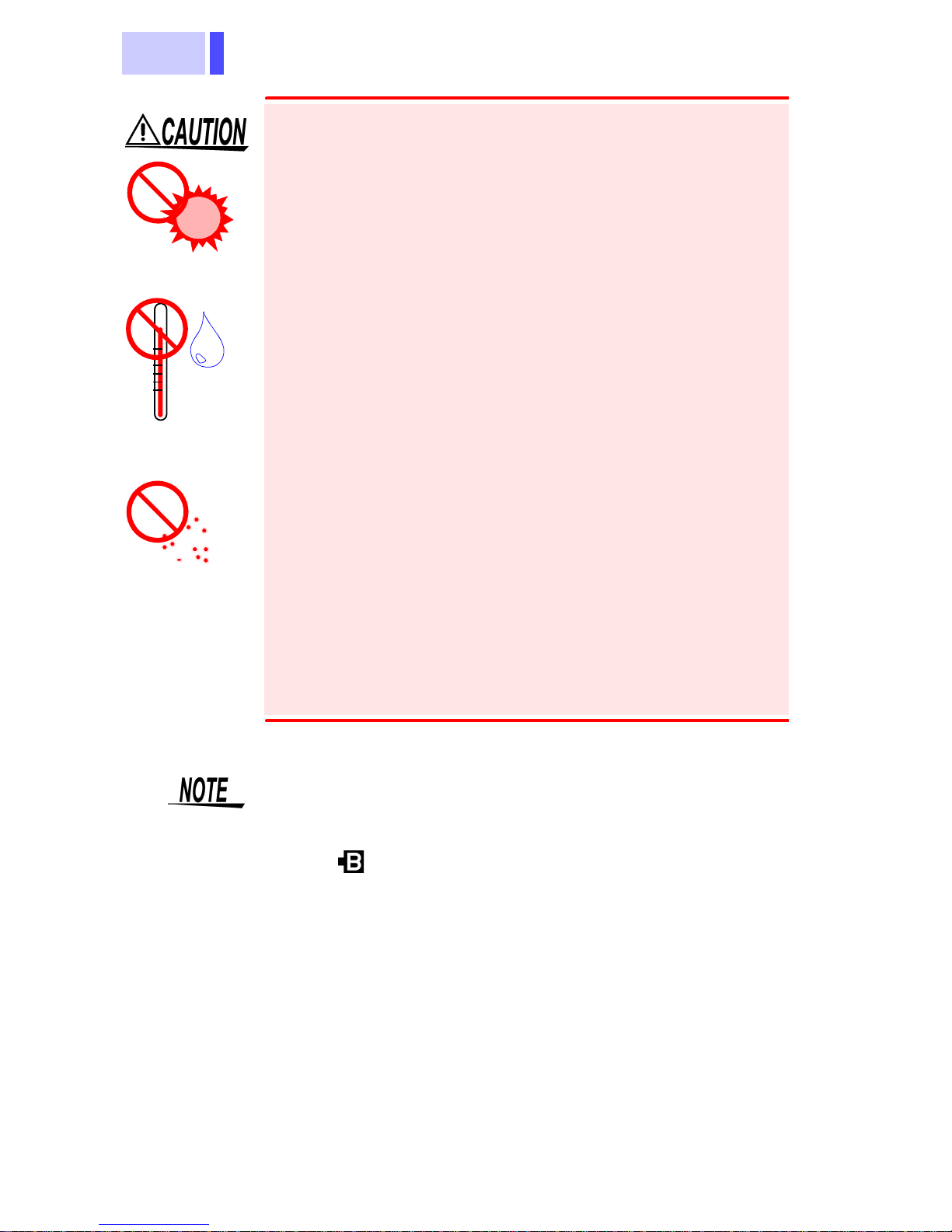
Follow these precautions to ensure safe operation
and to obtain the full benefits of the various functions.
Usage Notes
• When cleaning the connector of a optical
fiber cable, never look directly into the end
of the optical fiber cable or observe it
through a magnifying glass if the cable is
connected to an operating optical output
device as this can lead to eye damage or
visual impediment.
• To avoid a shock hazard, disconnect the
USB cable before replacing the batteries.
Page 12
8
• Do not store or use the product where it could
be exposed to direct sunlight, high temperature
or humidity, or condensation. Under such conditions, the product may be damaged and insulation may deteriorate so that it no longer meets
specifications.
• To avoid damage to the product, do not allow
the product to get wet, and do not use it when
your hands are wet.
• Do not use the product where it may be exposed
to corrosive or combustible gases. The product
may be damaged.
• To avoid damage to the product, protect it from
vibration or shock during transport and handling,
and be especially careful to avoid dropping.
• The mating portions of the detector and of the
connector adapter are high-precision machined
parts. Make sure that these portions are free of
dust or other foreign matter when connecting
them. In particular, the detector window requires
meticulous care. If there is dust in the interface
or a scratch on the detector window, the meter
may not satisfy performance specifications.
Direct
sunlight
High temperatur
e
High humidity
Dust
• After use, always turn OFF the power.
• Be sure to replace the cap to protect the device
from dust when the meter is not in use.
• The “ ” indicator appears when battery voltage
becomes low. Replace the batteries as soon as
possible.
• Use the specified battery (LR6 alkaline battery)
only. Other batteries (manganese batteries, for
example) run out more quickly than alkaline batteries.
Page 13
9
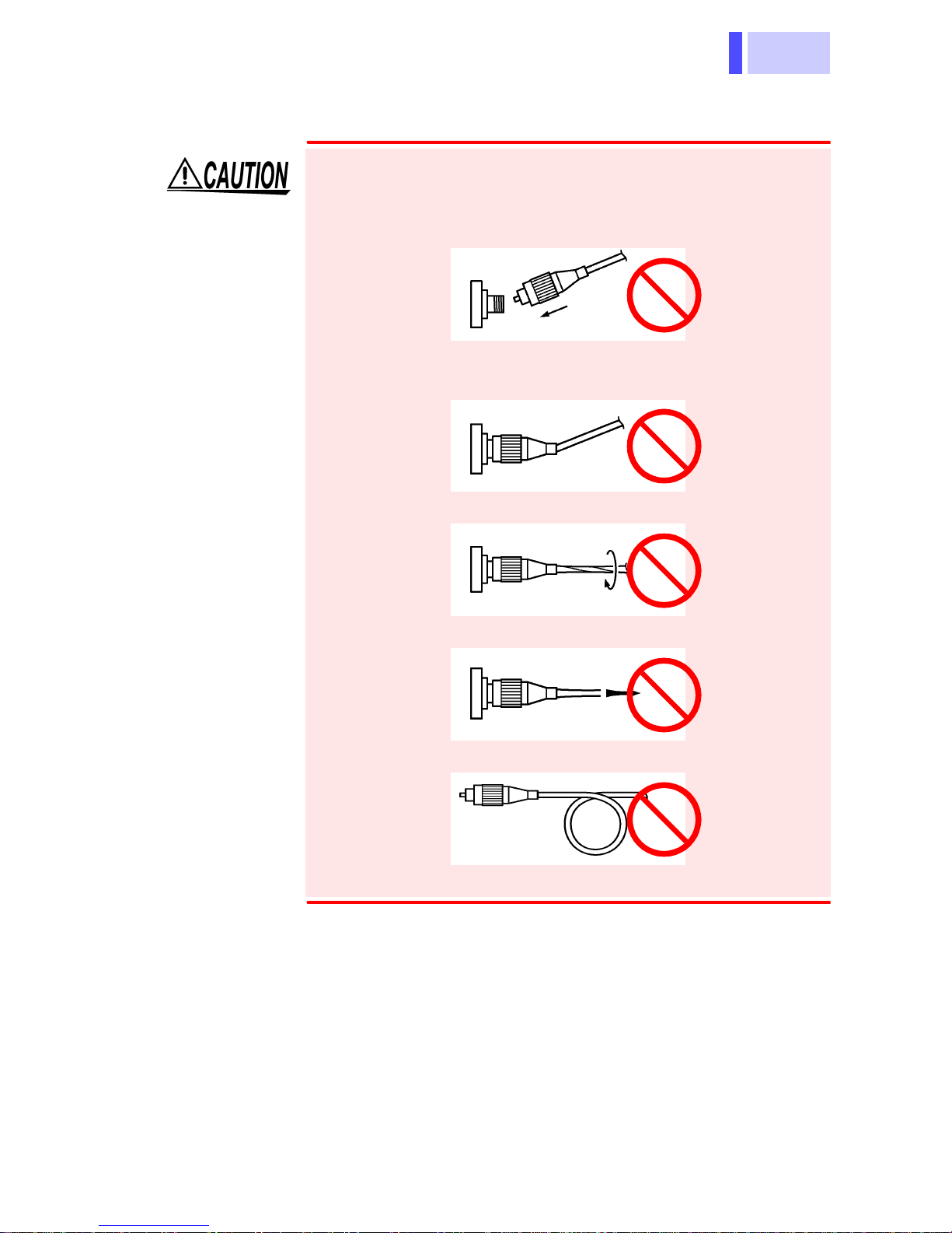
Handling Optical Fiber Cable
Follow the precautions below to prevent damage
to the optical fiber cables.
• Do not insert at an angle.
• Do not bend the cable at the neck of the connector.
• Do not bend or twist.
• Do not pull forcefully.
• Do not allow cable to kink.
• Do not touch the end face (ferrule).
Page 14

10
Care and handling of CD-R
• Always hold the disc by the edges, so as not to
make fingerprints on the label side or scratch
the printing.
• Never touch the recorded side of the disc. Do
not place the disc directly on anything hard.
• Do not wet the disc with volatile alcohol or water,
as there is a possibility of the label printing disappearing.
• To write on the disc label surface, use a spiritbased felt pen. Do not use a ball-point pen or
hard-tipped pen, because there is a danger of
scratching the surface and corrupting the data.
Do not use adhesive labels.
• Do not expose the disc directly to the sun's rays,
or keep it in conditions of high temperature or
humidity, as there is a danger of warping, with
consequent loss of data.
• To remove dirt, dust, or fingerprints from the
disc, wipe with a dry cloth, or use a CD cleaner.
Always wipe radially from the inside to the outside, and do no wipe with circular movements.
Never use abrasives or solvent cleaners.
• Hioki shall not be held liable for any problems
with a computer system that arises from the use
of this CD-R, or for any problem related to the
purchase of a Hioki product.
Page 15

11
1.1 Product Overview
The 3661-20 OPTICAL POWER METER is an
optical power measuring instrument for optical
fiber cables. The meter has two measurement
modes: optical-power measurement mode and
optical-loss measurement mode. In optical-loss
measurement mode, the meter calculates optical
loss by using the measurement and the reference
value stored in the memory.
Memory functions and a USB interface are provided so that saved measurement values can be
transferred to a PC using the supplied software.
Overview
Chapter 1
1.1 Product Overview
Page 16

1.2 Features
12
Two Measurement Modes
(Optical power measurement mode)
Measures the optical power of the cable connected to the meter.
(Optical loss measurement mode)
Stores a reference measurement in advance, then
takes a measurement and calculates optical loss
from the measurement and the reference.
Measurement wavelengths are programmable in 5 nm steps
Using the supplied software, practically any wavelength can be programmed for measurement in 5
nm steps. Up to eight programmed wavelengths
are stored in internal memory, and optical power
can be measured at each stored wavelength.
Supports Two Types of Optical Connectors
Supports both FC and SC type optical connectors;
use an appropriate connector adapter (a second
adapter is optional).
Memory Function
Saves measurements in the built-in memory; up to
1000 measurements per programmed measurement wavelength can be stored.
Transferring Data to PC
The provided USB interface enables saved data to
be transferred to a PC using the supplied software.
Auto Power Save Function
If there is no key operation for more than approximately ten minutes, the power of the meter is automatically turned off. This prevents the meter from
being left on unintentionally and minimizes battery
consumption.
1.2 Features
Page 17

13
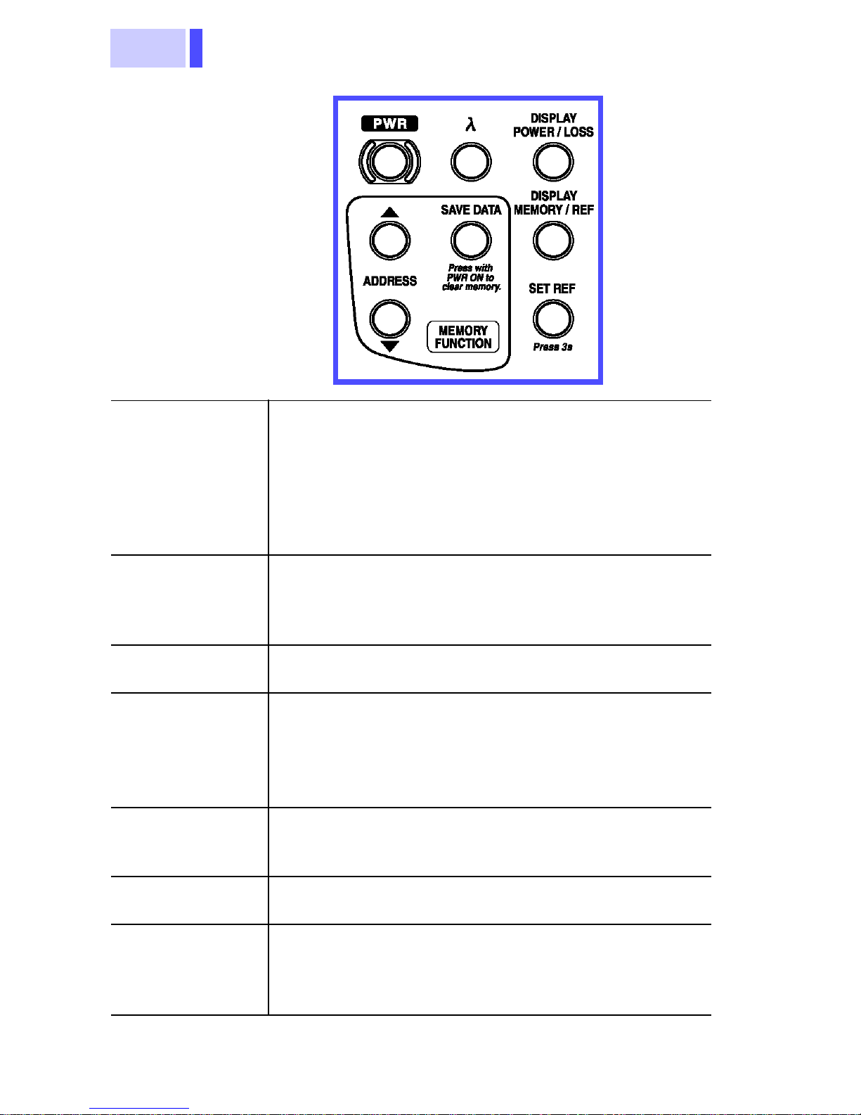
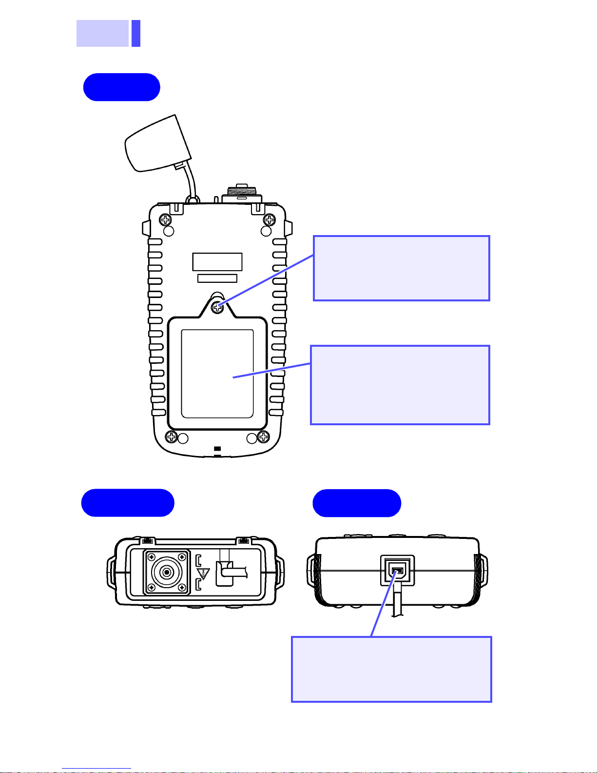
1.3 Parts Names and Functions
1.3 Parts Names and Functions
Front
Connector
adapter
Cap
Detector
Control keys
Connector
Adapter
Attach the connector adapter to the detector.
Choose the FC or SC type according to the
type of cable connector to be connected (a
second adapter is optional).
Detector Receives an optical signal.
Cap
Protects and dust-proofs the detector and
the connector adapter.
Be sure to replace the cap when the meter
is not in use.
Page 18
1.3 Parts Names and Functions
14
PWR
(Power switch)
Turns the power of the meter on and off.
Power ON
: Hold down the key for approximately two seconds to turn the power on. If it
is depressed for approximately five seconds,
the auto power save function is disabled.
Power OFF
: Hold down the key for approxi-
mately one second to turn the power off.
λ
(Wavelength
select)
Selects the measurement wavelength.
The measurement wavelength setting changes
as shown below each time the key is pressed.
1310 nm→1550 nm→ 850 nm →1310 nm →..
DISPLAY
POWER/LOSS
Selects optical power measurement mode or
optical loss measurement mode.
DISPLAY
MEMORY/REF
• Optical power measurement mode
Allows the memory data to be displayed.
• Optical loss measurement mode
Allows either the memory data or reference
value to be displayed.
SET REF
Hold down the key for approximately three
seconds to store the optical power measurement as a reference value.
ADDRESS
Press this key while the memory data is displayed to change the memory address.
SAVE DATA
Press this key while the memory data is displayed to store the measurement. By holding
down this key while turning the power ON, all
data stored in memory are deleted.
Control Keys
Page 19
15
1.3 Parts Names and Functions
Display (LCD)
Battery
Auto power save indicator
Optical power/loss
Measurement
Memory address
Reference
wavelength
indicator
Memory data
Optical Power/
Loss
Display the measurement mode.
POWER
: Optical power measurement mode
LOSS
: Optical loss measurement mode
Auto Power Save
Indicator
Lights when the auto power save function is
enabled.
If there is no key operation for more than
approximately ten minutes, the power of
the meter is automatically turned off. To
disable the function, hold down the power
switch key for approximately five seconds
when turning on the power.
Battery Indicator
Lights when the charge level in the battery
is low.
Measurement
Wavelength
Displays the measurement wavelength.
Reference
Displays the stored reference value.
Stores one reference value for every wavelength.
Memory Data
Displays the measurement stored in the
memory with the specified address.
Memory Address Displays the memory address.
Page 20
1.3 Parts Names and Functions
16
Setscrew
Setscrew to fasten the
battery cover
Battery cover
Cover for the battery
7.1 "Battery Replacement"
(63 page)
Rear
Lower
Upper
USB connection terminal
Terminal to connect a USB
cable.
Page 21
17
2.1 Connecting Connectors
Measurement
Preparations
Chapter 2
2.1 Connecting Connectors
When cleaning the connector of a optical
fiber cable, never look directly into the end of
the optical fiber cable or observe it through a
magnifying glass if the cable is connected to
an operating optical output device as this can
lead to eye damage or visual impediment.
Make sure that the mating portions are free of dust
or other foreign matter when connecting a optical
fiber cable to the meter. In particular, the end face
(ferrule) requires meticulous care. If there is dust
in the interface or a scratch on the end face, the
measurement may not be accurate.
Always clean the optical connector end face
(ferrule) of the optical fiber cable before connecting.
Page 22
2.1 Connecting Connectors
18
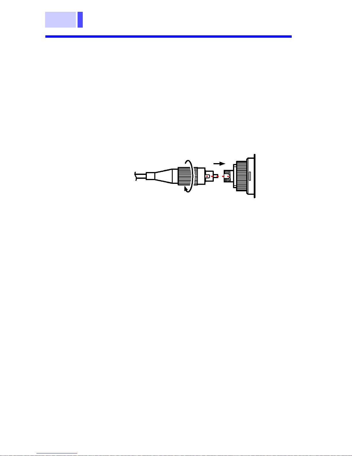
2.1.1 Connecting FC-Type Connector
1. Insert the end face (ferrule) of the optical fiber
cable into the connector adapter on the meter.
Make sure that the protrusion on the cable's
optical connector fits into the slot on the
connector adapter.
2. Rotate the knurled nut (connecting nut) to
tighten.
3661-20
1
2
Optical fiber cable
Page 23

19
2.1 Connecting Connectors
2.1.2 Connecting SC-Type Connector
Insert the end face (ferrule) of the optical fiber
cable into the connector adapter on the meter.
Fit the protrusion on the cable's optical connector
into the slot on the connector adapter. Push the
connector in until it clicks.
9735/9736/9737 OPTICAL FIBER CABLE
Specifications
3661-20
Optical fiber cable
The 9735, 9736, and 9737 (optional) are optical
fiber cables with ordinary optical connectors, not a
master connector.
Cable 1.3 μm-band single-mode optical
fiber cable
Connection
loss
0.5 dB or less
Return loss 45.0 dB or more
Minimum
bending radius
30 mm (Do not allow to remain
bent for a long time.)
Page 24
2.2 Turning ON/OFF Power
20
Power ON
Hold down the
PWR
key for approximately two
seconds.
The LCD screen lights and the power is turned on.
Power OFF
Hold down the
PWR
key for approximately one
second. The LCD screen goes out and the power
is turned off.
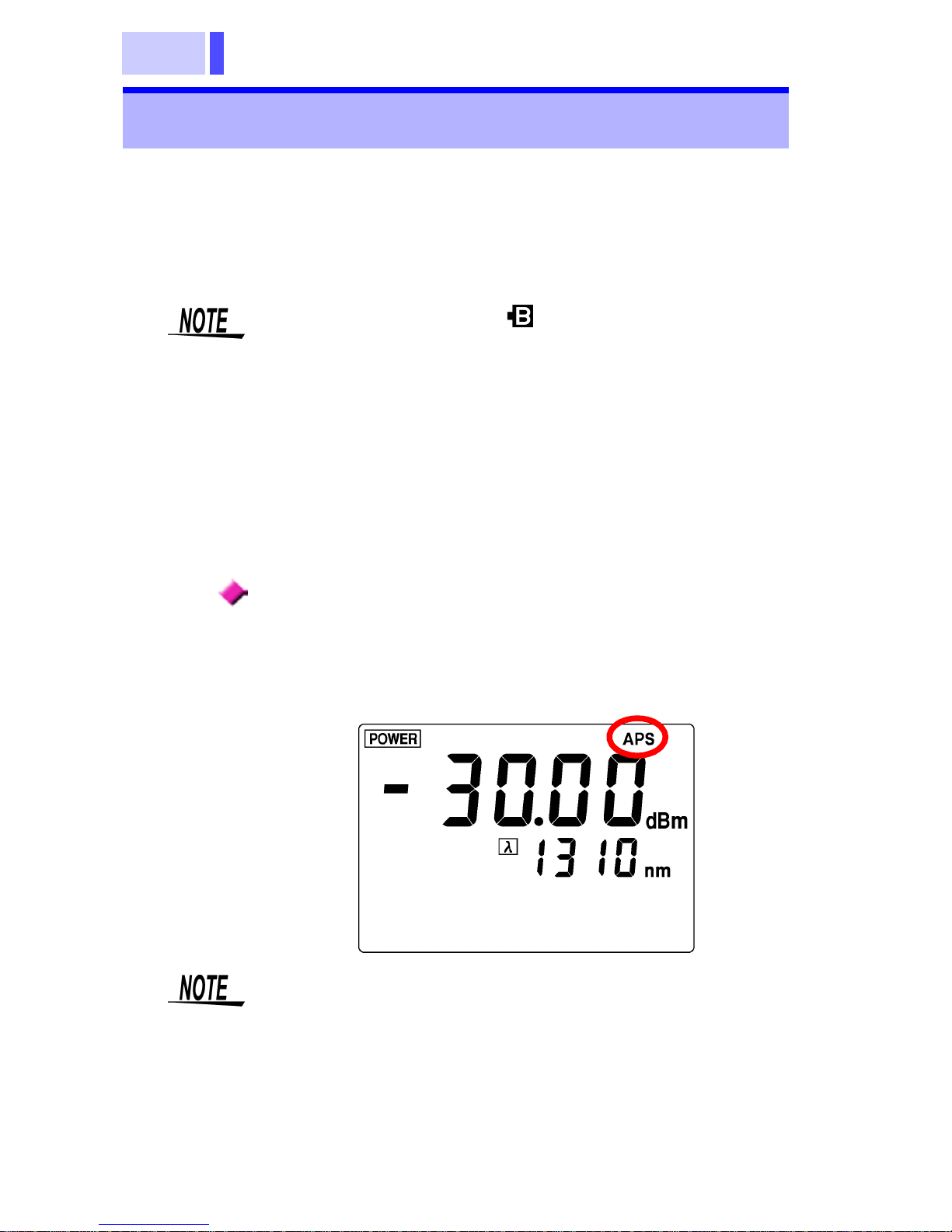
Auto Power Save Function
This function automatically turns off the power if
there is no key operation for more than ten minutes. ("
APS
" lights up in top right corner of the
screen.)
2.2 Turning ON/OFF Power
If the battery indicator ( in top right corner) is on
when the power is turned on, the battery is running
low. Replace it with a new battery.
7.1 "Battery Replacement" (63 page)
• The auto power save function is enabled when
the power is turned on in the normal procedure.
•
Disabling Auto Power Save Function
Hold down the
PWR
key for approximately five
seconds when turning on the power. "
APS
" goes
out and the auto power save function is disabled.
Page 25

21
2.3 Measurement Wavelength Programming
Wavelengths to be used for measurement are programmed in the meter before measuring.
• Measurement wavelengths are programmed
using the supplied software.
Programming measurement wavelengths →
5.5 "Programming Measurement Wavelengths"
(55 page)
• Any measurement wavelength can be programmed in 5 nm steps.
• Up to eight wavelengths can be programmed for
measurement (or fewer by deleting unneeded
wavelengths).
• The factory default (pre-programmed) wavelengths are 850, 1300, 1310, 1470, 1490,1550,
1625 and 1650 nm, which can be restored by
executing a system reset.
7.6 "System Reset" (71 page)
• Pressing the λ (Wavelength select) key displays
the currently programmed wavelengths.
2.3 Measurement Wavelength
Programming
Page 26

2.3 Measurement Wavelength Programming
22
Page 27

23
3.1 Optical Power Measurement
Performing optical power measurement and optical power loss measurement using a optical fiber
cable.
Perform optical power measurement using a optical fiber cable.
1. Press the
DISPLAY POWER/LOSS
key to
select optical power measurement mode.
"
POWER
" appears in the top left corner of the
screen.
Measurement
Chapter 3
3.1 Optical Power Measurement
Page 28

3.1 Optical Power Measurement
24
2. Pressing the λ (Wavelength select) key
repeatedly loads and displays each
programmed wavelength.
3. Connect the cable to be measured to the
meter.
2.1 "Connecting Connectors" (17 page)
4. The optical power measurement appears on the
LCD.
• For proper measurements, the measurement
wavelength has to match that of the light source.
• If the appropriate measurement wavelength is
not already programmed, program it using the
supplied software.
5.5 "Programming Measurement Wavelengths"
(55 page)
Cable to be measured
3661-20
Page 29

25
3.2 Optical Loss Measurement
Measures the optical loss of a optical fiber cable.
3.2.1 Saving Reference Value
Store a measurement to be used as a reference
for optical loss measurement.
1. Connect the light source and the meter using
the reference cable (a optical fiber cable used
as a reference).
2.1 "Connecting Connectors" (17 page)
3.2 Optical Loss Measurement
For optical loss measurement of a optical fiber
cable, the cable may be connected in several
ways. This section explains one of them as an
example.
Light Source
3661-20
Reference cable
Page 30

3.2 Optical Loss Measurement
26
2. Press
DISPLAY POWER/LOSS
key to select
optical power measurement mode.
"
POWER
" appears in the top left corner of the
screen.
3. Pressing the λ (Wavelength select) key
repeatedly loads and displays each
programmed wavelength.
• For proper measurements, the measurement
wavelength has to match that of the light source.
• If the appropriate measurement wavelength is
not already programmed, program it using the
supplied software.
5.5 "Programming Measurement Wavelengths"
(55 page)
Page 31

27
3.2 Optical Loss Measurement
4. Hold down the
SET REF
key for approximately
three seconds.
"
REF.DATA
" starts blinking and the measured
optical power is stored as a reference value.
The measurement mode changes from optical
power to optical loss and the measurement
reading becomes approximately 0.00 dB. (It
may not show exactly 0.00 dB depending on the
stability of the light source for measurement or
connection condition of the reference cable.)
A reference value is stored for every
wavelength.
Page 32

3.2 Optical Loss Measurement
28
3.2.2 Optical Loss Measurement
1. Press the
DISPLAY POWER/LOSS
key to
select optical loss measurement mode.
"
LOSS
" appears in the top left corner of the
screen.
2. Pressing the λ (Wavelength select) key
repeatedly loads and displays each
programmed wavelength.
• For proper measurements, the measurement
wavelength has to match that of the light source.
• If the appropriate measurement wavelength is
not already programmed, program it using the
supplied software.
5.5 "Programming Measurement Wavelengths"
(55 page)
Page 33

29
3.2 Optical Loss Measurement
3. Leave the reference cable connected to the
light source and connect one end of the cable to
be measured to the meter connector.
Connect the other end via the fiber optical
adapter to the reference cable connected to the
light source.
4. The optical loss of the cable to be measured
appears on the LCD.
Light source
3661-20
Cable to be measured
Fiber optical adapter
Reference cable
Page 34

3.2 Optical Loss Measurement
30
Page 35

31
4.1 Storing Measurement Data
• The optical power measurements/optical loss
measurements are stored in the memory.
• Up to 1000 measurements (addresses 000 to
999) per measuring wavelength are stored.
• Data can be transferred to a PC using the bun-
dled application software.
5.3 "Transferring Measurement Data" (52
page)
• Stores a measurement in the memory.
• Saves a measurement to a specified address.
1. Performs optical power or optical loss
measurement.
Saving/Deleting
Measurement Data
(Memory Function)
Chapter 4
4.1 Storing Measurement Data
Page 36

4.1 Storing Measurement Data
32
2. Press the
DISPLAY MEMORY/REF
key to
display data in the memory.
("
MEM.ADDRESS
" and "
MEM.DATA
" appears
on the LCD.)
3. Press the
ADDRESS
key to set the address of
the memory to be stored.
: Moves to lower numbers.
: Moves to higher numbers.
4. Press the
SAVE DATA
key.
"
MEM.DATA
" starts blinking and the
measurement is stored in the memory.
When data is already stored at the address you
have specified, the old data is replaced with the
new data.
Page 37

33
4.2 Viewing Stored Measurement Data
View measurement data stored for a wavelength.
1. Press the λ (Wavelength select) key to select
the measurement wavelength of which you wish
to view the data.
2. Press the
DISPLAY MEMORY/REF
key to
display data in the memory.
("
MEM.ADDRESS
" and "
MEM.DATA
" appear
on the LCD.)
3. Press the
ADDRESS
key to select the address
at which the data is stored. The stored
measurement data appears under
"
MEM.DATA
."
4.2 Viewing Stored Measurement Data
Page 38

4.3 Deleting All Measurement Data
34
• Deletes all the measurements stored for a measurement wavelength. (All Delete)
• A complete deletion of the measurement data
can be also performed using the bundled data
transter software.
5.4 "Erasing Measurement Data" (54 page)
1. Turn on the power while holding down the
SAVE DATA
key.
2. "
CLr
" starts blinking and all the measurements
are deleted. The LCD shows the measurement
mode screen.
4.3 Deleting All Measurement Data
Blinking
The programmed measurement wavelengths and
each reference value is not deleted.
To delete the programmed measurement wavelengths and reference values, perform a system
reset.
7.6 "System Reset" (71 page)
Page 39

35
5.1 Installation
The following operations are available using a PC
connected with the USB cable and running the
supplied software:
• Transfer measurement data saved in the meter’s
memory to the PC
• Erase all measurement data from the meter’s
memory
• Program different measurement wavelengths
into the meter
Install the supplied driver and application program
on the PC.
Recommended System Requirements
Contents of CD-R
Using the Supplied Software
Chapter 5
5.1 Installation
OS Windows 98, Windows Me, Win-
dows 2000, Windows XP
The hardware, such as CPU, RAM,
and display, must meet the requirements recommended by the OS.
HDD space Ten megabytes or more of free disk
space
Interface USB Ver.1.1 or later (Only one meter
can be connected to a PC at a time.)
English Installation setup file for English OS
Japanese Installation setup file for Japanese OS
hi3661.inf Driver installation file
hiusb36.sys Device driver for the 3661-20’s USB
Page 40

5.1 Installation
36
5.1.1 Installing Driver
1. Turn on the meter.
2. Connect the meter to the PC using the supplied
USB cable.
3. When the meter is connected to a PC for the
first time, the PC automatically detects the
meter. The message "
New Hardware Found
"
appears on the screen and the hardware
detection wizard starts.
The steps of the wizard may vary from OS to
OS; follow the on-screen instructions and install
the device driver.
• Only one meter can be connected to a PC at a
time.
• Do not connect or disconnect the USB cable
while the meter is in operation.
• When a meter with a different serial number is
connected, the instrument may indicate that a
new device has been detected. In such case,
install the device driver by following the instructions appearing on the screen.
Page 41

37
5.1 Installation
The driver installation procedure is explained for each OS as
below.
WindowsXP
1. Insert the bundled CD-R Hioki 3661 USB Utility
into the CD-ROM drive.
2. The "
Found New Hardware Wizard
" dialog
box appears.
Check "Install the software automatically" and
then click the [
NEXT
] button.
Page 42

5.1 Installation
38
3. Click the [
Continue Anyway
] button.
After the button is clicked, Windows starts to
copy the files.
When the software is scanned by the OS, a
warning saying that this software has not been
certified by Microsoft is appear. Ignore the
warning and continue the installation.
4. Click the [
Finish
] button.
5. When the "
Found New Hardware Wizard
"
dialog box has disappeared, remove the CD-R
from the CD-ROM drive.
Page 43

39
5.1 Installation
Windows2000
1. The "
Found New Hardware Wizard
" dialog
box appears.
Click the [
NEXT
] button.
2. Insert the bundled CD-R Hioki 3661 USB Utility
into the CD-ROM drive.
3. Check "
Search for a suitable driver for my
device
" and click the [
Next
] button.
Page 44

5.1 Installation
40
4. Check "
CD-ROM drive
" (leave all other boxes
blank). Click the [
Next
] button.
5. Click the [
Next
] button.
Page 45

41
5.1 Installation
6. Click the [
Finish
] button.
7. When the "
Found New Hardware Wizard
"
dialog box has disappeared, remove the CD-R
from the CD-ROM drive.
Page 46

5.1 Installation
42
WindowsMe
1. Insert the bundled CD-R Hioki 3661 USB Utility
into the CD-ROM drive.
2. The "
Add New Hardware Wizard
" dialog box
appears.
Check "
Automatic search for a better driver
"
and click the [
Next
] button.
3. Click the [
Finish
] button.
4. When the "
Add New Hardware Wizard
" dialog
box has disappeared, remove the CD-R from
the CD-ROM drive.
Page 47

43
5.1 Installation
Windows98
1. The "
Add New Hardware Wizard
" dialog box
appears.
Click the [
Next
] button.
2. Check "
Search for the best driver for your
device
" and click the [
Next
] button.
3. Insert the bundled CD-R Hioki 3661 USB Utility
into the CD-ROM drive.
Page 48

5.1 Installation
44
4. Check "CD-ROM drive" (leave all other boxes
blank). Click the [
Next
] button.
5. Click the [
Next
] button.
After the button is clicked, Windows starts to
copy the files.
Page 49

45
5.1 Installation
6. After a short time, the screen below appears;
click the [
Finish
] button.
7. When the "Add New Hardware Wizard" dialog
box has disappeared, remove the CD-R from
the CD-ROM drive.
Page 50

5.1 Installation
46
5.1.2 Installing Application Software
Installing
1. Close all currently active applications on the
PC.
2. Insert the CD-R Hioki 3661 USB Utility supplied
with the instrument into the CD-ROM drive.
3. Open the folder [
English
] included on the CD-
R, then execute Setup.exe.
This activates the installer and open the "
Hioki
3661 USB Utility
" window.
4. Click [
Next
].
Page 51

47
5.1 Installation
5.
To set up the installing destination:
Select [
Custom
] and click [
Next
].
Click [
Change
] in the "
Custom Setup
" window,
then specify the installing destination folder.
To install by default:
Select [
Complete
] and click [
Next
].
6. Click [
Install
].
Page 52

5.1 Installation
48
7. When installation ends, click [
Finish
] in the
checking window.
Installation is now complete.
Select [
Program
] - [
HIOKI
] - [
Hioki 3661 USB
Utility
] from the [
Start
] menu of Windows to acti-
vate the application.
Uninstallation
1. Select [
Setup
] - [
Control Panel
] from the
[
Start
] menu, then click [
Add/Remove
Programs
].
2. Select "
Hioki 3661 USB Utility
," then click
[
Remove
] or [
Change/Remove
].
3. Uninstall the program by following the
procedure appearing on the screen.
Page 53

49
5.2 Connecting the Meter to a PC
1. Turn on the meter.
2. Connect the meter to the PC using the supplied
USB cable (insert the plugs firmly).
The meter displays "
USb
", and all keys except
PWR
are disabled.
3. Start the Hioki 3661 USB Utility.
5.2 Connecting the Meter to a PC
The APS (auto power save) function is effective
even when the meter is connected to a PC with the
USB cable. When the APS function is on, if there
is no communication for approximately ten
minutes the power of the meter is automatically
turned off.
Page 54

5.2 Connecting the Meter to a PC
50
4. The list of measurement wavelengths and
measured values is displayed.
Page 55

51
5.2 Connecting the Meter to a PC
• If, as shown below, the list of measurement
wavelengths and measured values does not
appear, verify the USB connections.
• Do not disconnect the meter from the PC while
the application program is running.
• Exit the application program before disconnecting
the meter from the PC. Avoid connecting and disconnecting the meter from the PC unnecessarily,
as this could reduce battery charge capacity.
• When conforming the connection of the 3661
with the PC, select [
Communication
]-[
Check
connection
] on the Hioki 3661 USB Utility menu
bar.
Page 56

5.3 Transferring Measurement Data
52
Stored measurement data (measured optical
power and loss values) for each programmed
measurement wavelength is transferred from the
meter to the PC in CSV format.
1. Connect the meter to the PC using the supplied
USB cable.
2. Start the Hioki 3661 USB Utility.
5.2 "Connecting the Meter to a PC" (49 page)
3. Transfer measurement data from the meter's
memory.
•
To transfer data for a specific wavelength:
After clicking the check box for the measurement
wavelength of the data to transfer, select
[
Communication
]-[
Read
] on the Hioki 3661
USB Utility menu bar, or left click (Read)
on the tool bar.
•
To transfer data for all programmed wavelengths:
Select [
Communication
]-[
Read all
] on the Hioki
3661 USB Utility menu bar, or left click
(Read All) on the tool bar.
5.3 Transferring Measurement Data
Do not disconnect the USB cable while transferring.
Page 57

53
5.3 Transferring Measurement Data
4. Decide the destination to save the data, and
click [
Save
].
Example of Transferred Data (Excel display)
5. Exit the Hioki 3661 USB Utility.
6. Disconnect the USB cable from the meter and
the PC.
A comment can be attached to the file.
Page 58

5.4 Erasing Measurement Data
54
All measurement data stored in the meter can be
erased (Erase All).
1. Connect the meter to the PC using the supplied
USB cable.
2. Start the Hioki 3661 USB Utility.
5.2 "Connecting the Meter to a PC" (49 page)
3. Select [
Communication
]-[
Erase
] on the Hioki
3661 USB Utility menu bar, or left click
(Erase) on the tool bar.
4. Exit the Hioki 3661 USB Utility.
5. Disconnect the USB cable from the meter and
the PC.
5.4 Erasing Measurement Data
Deleted measurement data cannot be restored.
Because erased measurement data cannot be
recovered, transfer needed measurement data
before erasing.
5.3 "Transferring Measurement Data" (52 page)
Page 59

55
5.5 Programming Measurement Wavelengths
Measurement wavelengths are programmed in the
meter.
• Any measurement wavelength can be programmed in 5 nm steps.
• Up to eight wavelengths are programmed for
measurement (or fewer by deleting unneeded
wavelengths).
1. Connect the meter to the PC using the supplied
USB cable.
2. Start the Hioki 3661 USB Utility.
5.2 "Connecting the Meter to a PC" (49 page)
3. Select [
Communication
]-[
Edit
] on the Hioki
3661 USB Utility menu bar, or left click
(Edit) on the tool bar to display the Wavelength
Settings screen.
5.5 Programming Measurement Wavelengths
Page 60

5.5 Programming Measurement Wavelengths
56
4. Click the check box for the measurement
wavelength of the data to delete from
"
Wavelength list
", and left click [
Delete
].
Screen Description
Delete Deletes selected wavelength data
from the "
Wavelength list
".
Add Adds the wavelength specified by
"
Wavelength [nm]
" to the
"
Wavelength list"
.
Asterisks (*) indicate added wavelengths. If a wavelength cannot be
added, delete an existing wavelength first (a maximum of eight
wavelengths can be programmed).
Apply
The wavelengths in the
"
Wavelength list
" are pro-
grammed in the meter.
Close Closes the Wavelength Settings
screen.
Page 61

57
5.5 Programming Measurement Wavelengths
5. Program the wavelength to add with
"
Wavelength[nm]
", and left click [
Add
]. The
wavelength is added to the "
Wavelength list
",
and marked with an asterisk. Repeat to
program multiple wavelengths.
6. Left click [
Apply
]. The wavelengths in the
"
Wavelength list
" are programmed in the
meter.
7. Left click [
Close
] to close the Wavelength Set-
tings screen.
8. Exit the Hioki 3661 USB Utility.
9. Disconnect the USB cable from the meter and
the PC.
• A wavelength is not programmed in the meter
until you left click [
Apply
].
• Because measurement and reference value data
for deleted wavelengths is erased, be sure to
transfer needed measurement data before reprogramming wavelengths.
5.3 "Transferring Measurement Data" (52 page)
Page 62

5.5 Programming Measurement Wavelengths
58
Page 63

59
6.1 Measurement Specifications
Specifications
Chapter 6
6.1 Measurement Specifications
Measurement
function
Optical power measurement, optical loss
measurement
• Optical power measurement
Measures the absolute value of input
power. (Unit: dBm)
• Optical loss measurement
Uses optical power as a reference to automatically calculate the difference between
that reference and the measurement
undertaken. (Unit: dB)
Calibration
wavelength
850 nm, 1310 nm, 1550 nm
Measurement
wavelengths
800 to 1660 nm (up to eight wavelengths
can be programmed in 5 nm steps)
Pre-programmed measurement wavelengths: 850, 1300, 1310, 1470, 1490,1550,
1625 and 1650 nm (Programable in 5 nm
steps)
Measuring range -60 dBm to +9 dBm, auto-ranging
Measuring
accuracy
±
0.22 dB ( ±5% )
(Conditions for guarantee)
Wavelength: Hioki's standard wavelength
for 1310 nm or 1550 nm
*
Power: -10 dBm, continuous wave (CW)
Optical fiber: Single mode fiber, FC master
connector, PC polishing
Page 64

6.1 Measurement Specifications
60
Operating
temperature and
humidity for guaranteed accuracy
Period of guaranteed accuracy
23
±
5°C (73±41°F), 80%RH or less
1 year
Resolution Optical power measurement: 0.01 dBm
Optical loss measurement : 0.01 dB
Maximum rating +10 dBm
Detector type InGaAs
Detector size
φ
1 mm
Screenupdating rate
Approx. 350 ms
Display LCD
Optical fiber Single mode, multi mode
(Core diameter
62.5 μm, NA 0.275)
Connector FC, SC
(Use the optional connector adapter.)
Memory function • Memory storage
Stores a measurement at an address of
between 000 and 999; if there is already
data at the specified address, the old data
is replaced by the new data.
• Memory deletion
All data is deleted at once.
(Press the SAVE DATA key when turning
on power.)
• Number of Memory Data
1000 measurements for every wavelength
Page 65

61
6.1 Measurement Specifications
*: Hioki's Standard Wavelength
The term "Hioki's standard wavelength" is used to avoid
ambiguity in the conditions for the measurement accuracy
guarantee.
The calibration wavelength is a value inherent to a light
source for adjustment and calibration. The sensitivity of a
detector is usually dependent on wavelength, but varies
from element to element. Furthermore, the output beam of
a laser light source has a wavelength inherent to each light
source. A fixed wavelength cannot be set for the sake of
product maintenance.
Additional
functions
• Auto power save
Power is turned off automatically if there is
no key operation for more than ten minutes.
To disable the function, hold down the
PWR key for more than five seconds when
turning the power on.
• Settings backup
The settings at the time of shutdown are
saved and the meter is started up with the
saved settings when the power is turned
on again.
• Battery check
If the battery voltage falls below 4 V, the
battery indicator lights.
(Accuracy is not guaranteed when the indicator is on.)
Interface USB Ver1.1
Content of communications: Measurement
data in the memory is transferred to a PC .
Programming measurement wavelengths
(using the bundled application software)
Page 66

6.2 General Specifications
62
6.2 General Specifications
Rated power
supply
DC1.5 V X 4
LR6 alkaline battery 1.5 V X 4
Maximum rated
power
0.5 VA
Operating time Continuous measurement: Approx. 40 hours
(Ambient temperature of 23°C (73°F))
Size Approx. 85W X 192H X 35D mm (3.35"W X
7.56"H X 1.38"D) (excluding projections)
Weight Approx. 300 g(10.6 oz.) (excluding batteries)
Operating
temperature
and humidity
0 to 40°C (32 to 104°F), 80%RH or less
(no condensation)
Storage
temperature
and humidity
-10 to 50°C (14 to 122°F), 80%RH or less
(no condensation)
Operating
environment
Indoors, altitude up to 2000 m (6562 feet)
Applicable
standards
Safety EN61010-1:2001 Pollution Degree 2
EMC EN61326:1997+A1:1998+A2:2001+
A3:2003
Accessories
3853 CARRYING CASE............................ 1
CD-R of application software .................... 1
LR6 alkaline battery .................................. 4
USB cable (1 m)........................................ 1
Strap.......................................................... 1
Instruction manual..................................... 1
Options 9730 CARRYING CASE
9731 FC CONNECTOR ADAPTER
9732 SC CONNECTOR ADAPTER
9735 FC-FC OPTICAL FIBER CABLE
9736 SC-SC OPTICAL FIBER CABLE
9737 SC-FC OPTICAL FIBER CABLE
9738 OPTICAL CONNECTOR CLEANER
9739 SPARE CLEANER
Page 67

63
7.1 Battery Replacement
Maintenance and
Service
Chapter 7
Never modify the instrument. Only Hioki service
engineers should disassemble or repair the instrument. Failure to observe these precautions may
result in fire, electric shock, or injury.
7.1 Battery Replacement
• To avoid a shock hazard, disconnect the USB
cable before replacing the batteries.
• After replacing the batteries, replace the cover
and screws before using the product.
• Do not mix old and new batteries, or different
types of batteries. Also, be careful to observe
battery polarity during installation. Otherwise,
poor performance or damage from battery leakage could result.
• To avoid the possibility of explosion, do not short
circuit, disassemble or incinerate batteries.
• Handle and dispose of batteries in accordance
with local regulations.
• To avoid corrosion from battery leakage, remove
the batteries from the product if it is to be stored
for a long time.
• If a optical fiber cable is bent or twisted, this may
result in damage to the cable. Be sure to disconnect the optical fiber cable before replacing the
battery.
Page 68

7.1 Battery Replacement
64
If the “ ” indicator is blinking when power is
turned on, the battery is running low. Replace with
a new battery.
1. Turn off power and disconnect the optical fiber
cable from the meter.
2. Remove the setscrew and open the battery
cover.
3. Replace four batteries.
4. Replace the battery cover and tighten the
setscrew.
• The “ ” indicator appears when battery voltage
becomes low. Replace the batteries as soon as
possible.
• Use the specified battery (LR6 alkaline battery)
only. Other batteries, (manganese batteries, for
example) run out more quickly than alkaline batteries.
Page 69

65
7.2 Attaching/Detaching Connector Adapter
Attaching Procedure
Fit the connector adapter onto the detector and
rotate it clockwise. Tighten it by hand.
Detaching Procedure
Rotate the connector adapter counter-clockwise to
remove it.
7.2 Attaching/Detaching Connector
Adapter
The mating portions of the detector and the connector adapter are machined to a high degree of
precision. Make sure that those portions are free
of dust or other foreign substances before connecting them. In particular, the detector window
needs meticulous care; if there is dust in the interface or a scratch on the detector window, the
meter may not satisfy performance specifications.
Be sure to replace the cover to the main device
and the adapter's dust cap for protection against
damage and dust when the meter is not in use.
Page 70

7.3 Attaching the Strap
66
Use the strap to carry the instrument, or to hang it
up at the installation location.
7.3 Attaching the Strap
Attach both ends of the strap securely to the
instrument. If insecurely attached, the instrument
may fall and be damaged when carrying.
1.
Insert each end of
the strap through
an installation slot
on the instrument.
2.
Feed each end of
the strap through
its clasp.
3.
Feed each end
through its stopper.
Attaching the strap
Tighten the strap sufficiently to prevent loosening or twisting.
3661-20
Page 71

67
7.4 Cleaning
7.4.1 Cleaning the Product
To clean the product, wipe it gently with a soft cloth
moistened with water or mild detergent. Never use
solvents such as benzene, alcohol, acetone, ether,
ketones, thinners or gasoline, as they can deform
and discolor the case.
7.4.2 Cleaning Detector Window
1. Remove the connector adapter.
2. Gently wipe the detector window using a lens
cleaning paper or other lint-free material.
If fibers are left on the detector window, blow
them off using a blower brush designed for
optical lenses.
If necessary, gently clean the surface with a
lens cleaning liquid or ethyl alcohol.
7.4 Cleaning
• Do not touch the detector window. If the detec-
tor window is not clean, the meter may not satisfy performance specifications.
• Do not use organic solvents other than ethyl
alcohol as they may damage the detector window.
• Be sure not to damage the detector window with
a sharp object (e.g., the tip of a pair of tweezers)
or hard surface. If the detector window is damaged, the meter may not satisfy performance
specifications.
Page 72

7.4 Cleaning
68
7.4.3 Cleaning Cable Connector
Use the 9738 OPTICAL CONNECTOR CLEANER
to clean the connector of the optical fiber cable.
When cleaning the connector of a optical
fiber cable, never look directly into the end of
the optical fiber cable or observe it through a
magnifying glass if the cable is connected to
an operating optical output device as this can
lead to eye damage or visual impediment.
When cleaning the end of the optical connector, do
not apply too much force with the cleaning cloth.
This may result in damage to the connector and
the meter may consequently fail to satisfy performance specifications.
Page 73

69
7.4 Cleaning
1. Squeeze the lever of the 9738 OPTICAL
CONNECTOR CLEANER and the shutter
opens, revealing the cleaning cloth.
2. While squeezing the lever, gently press the end
of the optical connector against the cleaning
surfaces (cleaners held in the slot shown) at a
right angle. Slide the connector once in the
direction of the arrow marked on the cleaners.
3. Slide the connector once per cleaning surface.
There are two cleaning surfaces; thus slide the
connector a total of two times. Release the
lever and the shutter shuts.
1
2
Cleaning surface
Always clean the optical connector end face
(ferrule) of the optical fiber cable before
connecting.
Page 74

7.5 Error Indication
70
When an error occurs, an error indication appears
on the LCD as shown below.
7.5 Error Indication
Err0
"
Err0
" appears when an inappropriate
value is stored as a reference.
If you store a measurement as a reference when the measurement is "Lo" or
"Hi" in optical power measurement,
"
REF.DATA
" blinks and "
Err0
" appears.
(The reference value is updated.)
Press any key except the
PWR
key,
and "Lo" (or "Hi") is shown for the reference data. The optical loss measurement shows "
----
." If the
measurement data is stored, "---- dB"
is stored, but not transffered to the PC.
(It is included in the number of data.)
Err1
The calibration value may be corrupted. All the keys except for the
PWR
key are disabled and you cannot
perform measurement. (Data transfer
by USB communications is not available either.)
The meter may be malfunctioning.
Contact your vender or nearest Hioki
office.
Page 75

71
7.6 System Reset
Turn on the power while holding down the
ADDRESS
key + . The screen shown below
is displayed. After the system reset has been
completed, the optical power measurement mode
screen appears.
Details of System Reset
System reset initializes the following (returns them
to default setting).
Measurement mode:
Optical power measurement mode
Measurement wavelength: 1310 nm
Pre-programmed measurement wavelengths:
850 nm, 1300 nm, 1310 nm, 1470 nm, 1490 nm,
1550 nm, 1625 nm, 1650 nm
Reference:
0 dBm (for all the measurement wavelengths)
Memory: No data (All the addresses for all the
measurement wavelengths)
7.6 System Reset
Blinking
Page 76

7.7 Service
72
• If the product seems to be malfunctioning, confirm that the batteries are not discharged, and
that the USB cable, optical fiber cable are not
open circuited before contacting your dealer or
Hioki representative.
• When sending the product for repair, remove the
batteries and pack carefully to prevent damage
in transit. Include cushioning material so the
instrument cannot move within the package. Be
sure to include details of the problem. Hioki cannot be responsible for damage that occurs during
shipment.
7.7 Service
Page 77

73
8.1 Explanations
Optical Power Measurement
Assuming the energy of the input light to be measured is "E" [mW], the measurement "P" is
obtained as below.
P: Measurement [dBm]
E: Energy of input light [mW]
Optical Loss Measurement
Loss of optical energy "Ploss" is calculated from
the equation below, using the value obtained by
reference measurement "Pref" [dBm] and the measurement "P."
Ploss [dB] = Pref [dBm] - P [dBm]
Ploss: Optical loss [dB]
Pref : Reference [dBm]
P : Measurement [dBm]
Eref : Energy of light input through the reference
cable
E : Energy of light input through the cable to be
measured
Appendix
Chapter 8
8.1 Explanations
P [dBm] = 10log
10
1 [mW]
E [mW]
= 10log
10
1 [mW]
Eref [mW]
- 10log
10
1 [mW]
E [mW]
= - 10log
10
Eref
E
Page 78

8.2 Options
74
9730 CARRYING CASE
The carrying case houses the 3661-20 OPTICAL
POWER METER, 3662/3663 LASER LIGHT
SOURCE, connector adapters, reference cable,
and 9738 OPTICAL CONNECTOR CLEANER.
9731 FC CONNECTOR ADAPTER
FC connector adapter for the 3661-20 OPTICAL
POWER METER (with dust-cap attached)
9732 SC CONNECTOR ADAPTER
SC connector adapter for the 3661-20 OPTICAL
POWER METER (with dust-cap attached)
8.2 Options
Page 79

75
8.2 Options
9735 FC-FC OPTICAL FIBER CABLE
FC-to-FC reference cable (Length: 2 m)
9736 SC-SC OPTICAL FIBER CABLE
SC-to-SC reference cable (Length: 2 m)
9737 SC-FC OPTICAL FIBER CABLE
SC-to-FC reference cable (Length: 2 m)
Hioki's optional optical fiber cables (9735, 9736
and 9737) are optical fiber cables with an ordinary
optical connector. (They are not equipped with a
master optical connector.)
9735/9736/9737 OPTICAL FIBER CABLE
Specifications
Cable 1.3 μm-band single-mode optical
fiber cable
Connection
loss
0.5 dB or less
Return loss 45.0 dB or more
Minimum
bending
radius
30 mm (Do not allow to remain bent
for a long time.)
Page 80

8.2 Options
76
9738 OPTICAL CONNECTOR CLEANER
Cleaner for optical fiber cable connector
9739 SPARE CLEANER
Refill for the 9738 OPTICAL CONNECTOR
CLEANER (6-rolls)
Page 81

Page 82

Page 83

HIOKI 3661-20 OPTICAL POWER METER
Instr uction Manual
Publication date: September 2006 Revised edition 2
Edited and p ublished by HIOKI E .E. CORPO RATION
Technical Support Section
All inquiries to International Sales and Marketing De-
partment
81 Koizumi, Ueda, Nagano, 386-1192, Japan
TEL: +81-268-28-0562 / FAX: +81-268-28-0568
E-mail: os-com@hioki.co.jp
URL http://www.hioki.co.jp/
Printed in Japan 3661A981-02
• All reasonable care has been taken in the production
of this manual, but if you find any points which are
unclear or in error, please contact your supplier or the
International Sales and Marketing Department at
HIOKI headqu arte rs.
• In the interests of product development, the contents
of this manual are subject to revision without prior
notice.
• Unauthorized reproduction or copying of this manual
is prohibited.
Page 84

HEAD OFFICE
81 Koizumi, Ueda, Nagano 386-1192, Japan
TEL +81-268-28-0562 / FAX +81-268-28-0568
E-mail: os-com@hioki.co.jp
URL http://www.hioki.co.jp/
HIOKI USA CORPORATION
6 Corporate Drive, Cranbury, NJ 08512, USA
TEL +1-609-409-9109 / FAX +1-609-409-9108
3661A981-02 06-09H
Printed on recycled paper
 Loading...