

Page 1

INSTRUCTION MANUAL
For...は専用機種。複数の場合は「/」で区切る。
不要の場合はとる。
形名を入力。 複数の場合は「/」で区切る。
3640-20
品名を入力。
LUX LOGGER
Page 2

Page 3

Contents
Introduction i
Inspection ii
Safety Notes iii
Notes on Use v
Measurement Flow Chart and Reference Guide vi
Chapter 1 Product Overview 1
1.1 Name and Functions of Parts 2
1.2 Interval and Maximum Recording Time
Chapter 2 Set Up 5
2.1 Replacing the Battery 5
2.2 Power Save Function
2.3 Setting Current Time
2.4 Connecting 9662 LUX SENSOR
Chapter 3 Settings 11
3.1 Setting Items 11
3.2 Manual Setting
3.3 Setting by COMMUNICATION BASE
14
16
3
7
8
9
Chapter 4 Specifications 19
Chapter 5 Reference 21
5.1 Recommended Levels of Illumination 21
5.2 Relative Spectral Response Characteristics
in the Visible Spectrum
5.3 Angled Incident Light Characteristics
23
24
Chapter 6 Maintenance and Service 25
Page 4

Page 5

_____________________________________________________________________
Introduction
Thank you for purchasing this HIOKI "3640-20 LUX
LOGGER." To get the maximum performance from the
unit, please read this manual first, and keep this at hand.
i
______________________________________________________________
Introduction
Page 6

ii
_____________________________________________________________________
Inspection
When the unit is delivered, check and make sure that it has
not been damaged in transit. If the unit is damaged, or fails
to operate according to the specifications, contact your
dealer or HIOKI representative.
Accessories
9662 LUX SENSOR
Instruction Manual
LR03 alkaline battery X 4 (built into this unit, for monitor)
Before using the product the first time, verify that it
operates normally to ensure that the no damage occurred
during storage or shipping. If you find any damage, contact
your dealer or Hioki representative.
NOTE
______________________________________________________________
Inspection
Testing monitor batteries installed in the unit may possibly be
weak. Replace batteries before extended measurement usage.
Page 7

_____________________________________________________________________
R
iii
SafetyNotes
This equipment is designed according to IEC 61010-1
Safety Standards, and has been tested for safety prior
DANGE
Safety Symbols
to shipment. Incorrect measurement procedures
could result in injury or death, as well as damage to
the equipment. Please read this manual carefully and
be sure that you understand its contents before using
the equipment. The manufacturer disclaims all
responsibility for any accident or injury except that
resulting due to defect in its product.
This Instruction Manual provides information and warnings
essential for operating this equipment in a safe manner and
for maintaining it in safe operating condition. Before using
this equipment, be sure to carefully read the following
safety notes.
This symbol is affixed to locations on the equipment
where the operator should consult corresponding topics
in this manual (which are also marked with the
symbol) before using relevant functions of the
equipment.
In the manual, this mark indicates explanations which it
is particularly important that the user read before using
the equipment.
Indicates DC (Direct Current).
______________________________________________________________
Safety Notes
Page 8

iv
R
_____________________________________________________________________
The following symbols are used in this Instruction Manual
to indicate the relative importance of cautions and
warnings.
Indicates that incorrect operation presents extreme
DANGE
WARNING
CAUTION
NOTE
danger of accident resulting in death or serious injury
to the user.
Indicates that incorrect operation presents significant
danger of accident resulting in death or serious injury
to the user.
Indicates that incorrect operation presents possibility
of injury to the user or damage to the equipment.
Denotes items of advice related to performance of the
equipment or to its correct operation.
Accuracy
The specifications in this manual include figures for
"measurement accuracy" when referring to digital
measuring instruments, and for "measurement tolerance"
when referring to analog instruments.
f.s.
(maximum display or scale value, or length of scale)
Signifies the maximum display (scale) value or the length
of the scale (in cases where the scale consists of unequal
increments or where the maximum value cannot be
defined).
In general, this is the range value (the value written on
the range selector or equivalent) currently in use.
rdg.
(displayed or indicated value)
This signifies the value actually being measured, i.e., the
value that is currently indicated or displayed by the
measuring instrument.
dgt.
(resolution)
Signifies the smallest display unit on a digital measuring
instrument, i.e., the value displayed when the last digit on
the digital display is "1".
______________________________________________________________
Safety Notes
Page 9

_____________________________________________________________________
v
Notes on Use
In order to ensure safe operation and to obtain maximum
performance from the unit, observe the cautions listed
below.
CAUTION
NOTE
Do not store or use the product where it could be exposed
to high temperature or humidity, or condensation. Under
such conditions, the product may be damaged and
insulation may deteriorate so that it no longer meets
specifications.
Attach the supplied light sensor cap to the detector and then
perform zero ajustment before measurement.
Do not store or use the tester where it will be exposed to direct
sunlight, high temperature, high humidity, or condensation. If
exposed to such conditions, the tester may be damaged, the
insulation may deteriorate, and the tester may no longer satisfy
its specifications.
The reference level as marked on the faceplate is the tip of the
light sensor.
______________________________________________________________
Notes on Use
Page 10

vi
_____________________________________________________________________
Measurement Flow Chart and Reference Guide
Is there sufficient
battery charge remaining
to operate 364
Setting current time
Connecting sensor
Zero ajustment
Setting 3640-20
stand-alone
・Interval
・Range
See 3.2.
0-20?
Set current time when using 3640-20 for the
first time or replacingbatteries. See 2.3.
See 2.4.
See 2.4.
Setting 3640-20
with COMMUNICATION
・Interval
・Current time
・Start control
・Recording method
BASE
Quick start
No
Replace batteries
Setting 3640-20 with
COMMUNICATION BASE
・Interval ・Current time
・Start control ・Range
・Recording method
・Comment
Settingstart control
Start control options
and PC
Yes
Prescheduled start
See 2.1.
Press REC/STOP
button to start
measurement.
See 3.2.
When recording data
reaches 32000
measurement stops.
After measurement is complete, disconnect sensor. Use COMMUNICATION BASE to
send measurement data to personal computer. (See COMMUNICATION BASE
instruction manual.)
Starts measurement
immediately.
One time
recordingmethod
When recording data exceeds 32000, it overwrites
previously recorded data.
Press REC/STOP button to stop measurement.
Starts measurement at
prescheduled time.
Setting
Endless
______________________________________________________________
Measurement Flow Chart and Reference Guide
Page 11

_____________________________________________________________________
1
Chapter 1
Product Overview
3640-20 LUX LOGGER with 9662 LUX SONSOR records
1 channel of data at illuminance.
Data is saved in nonvolatile memory when batteries are
weak or removed for replacement.
NOTE
3640-20 LUX LOGGER are not able to set up it to 3910-20
COMMUNICATION BASE.
Use 3911-20, 3912-20 COMMUNICATION BASE to set 3640-
20.
______________________________________________________________
Page 12
2
(
_____________________________________________________________________
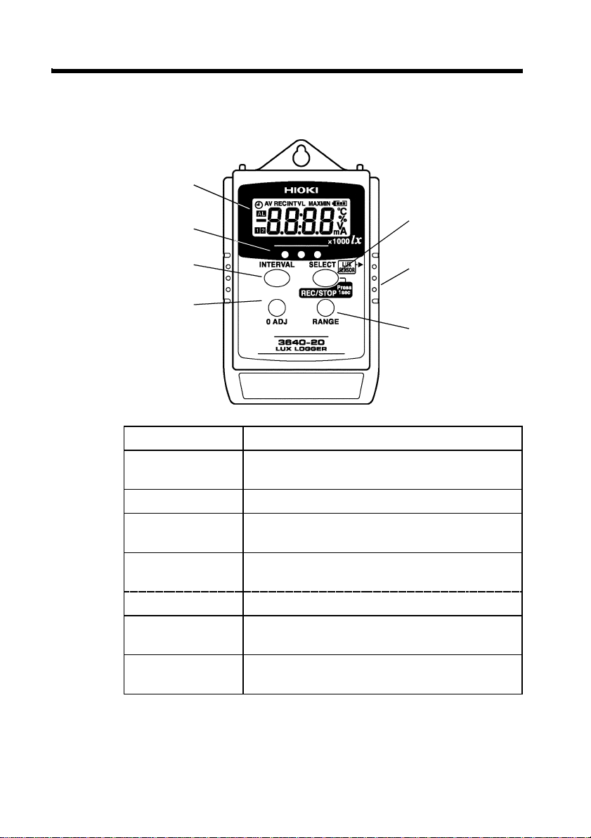
1.1 Name and Functions of Parts
LCD
Optical data
transferports
INTERVAL
button
Zero ajustment
button
LCD Displays measurement value and settings.
Optical data
transfer ports
INTERVAL button Calls up interval setting display to set interval.
Zero ajustment
button
REC/STOP button Pressing more than 1 second initiates or stops
(SELECT) button Interval is selected in interval setting display.
Sensor connection
terminal
Range button Changes measurement range from 2000
Enables optical data transfer to
COMMUNICATION BASE.
Performs zero adjustment for the Lux Sensor.
recording.
Connects 9662 LUX SENSOR.
lx/20000 lx/2000000 lx.
REC/STOP button
SELECT)button
Sensor connection
terminal
Range button
______________________________________________________________
1.1 Name and Functions of Parts
Page 13

_____________________________________________________________________
1.2 Interval and Maximum Recording Time
Interval and maximum recording time (when power save
function is valid) are as follows.
Maximum recordable data is 32000 per unit.
INTVL Maximum Recording Time
1s 8h53min20s
2s 17 h 46 min 40 s
5s 1 day 20 h 26 min 40 s
10 s 3 day 16 h 26 min 40 s
15 s 5 day 13 h 20 min
20 s 7day9h46min40s
30 s 11 day 2 h 40 min
1min 22 day 5 h 20 min
2min 44 day 10 h 40 min
5min 111 day 2 h 20 min
10 min 222 day 5 h 20 min
15 min 333 day 8 h
20 min 444 day 10 h 40 min
30 min 666 day 6 h
60 min 1333 day 8 h
3
______________________________________________________________
1.2 Interval and Maximum Recording Time
Page 14

4
_____________________________________________________________________
______________________________________________________________
1.2 Interval and Maximum Recording Time
Page 15

_____________________________________________________________________
5
Chapter 2
Set Up
2.1 Replacing the Battery
During battery replacement, use caution not to put any
WARNING
foreign materials such as a metal object into the unit to
avoid damage to the unit.
Before using the product after replacing the batteries,
replace the cover and screw.
Do not mix old and new batteries, or different types of
batteries. Also, be careful to observe battery polarity
during installation. Otherwise, poor performance or
damage from battery leakage could result.
Handle and dispose of batteries in accordance with
local regulations.
CAUTION
When exchanging the batteries, the circuit may sometimes
short circuit due to static electricity. As far as possible, do
not touch the base board with bare hands.
Installing new batteries ensures about 1 year of recording.
(reference value with interval setting set to 1 minute or
more, power save setting set to valid and at 20
Remaining battery power indicator (
)indicates
)
remaining battery life reducing incrementally from right.
Empty battery power indicator (
) indicates time to
replace batteries.
______________________________________________________________
2.1 Replacing the Battery
Page 16

6
_____________________________________________________________________
1. Remove back cover screw
to remove cover. Verify
polarity and install four
new LR03 alkaline
batteries.
2. Fit cover properly and
tighten screw.
______________________________________________________________
2.1 Replacing the Battery
Page 17

_____________________________________________________________________
7
2.2 Power Save Function
Display window is automatically turned off in
approximately 15 seconds after last key entry. (Sleep)
However, while recording,
conditions.
Press any button to turn display on to display measurement
value or to set settings.
Note when interval setting display is on, sleep does not
engage with no button press.
Initially, power save function is on. To turn off power save
function, follow the instructions below.
When power save function is off, maximum continuous
duration is approximately 10 days.
REC
/ / mark shows each
Sleeping......
1. Connect logger, COMMUNICATION BASE and
personal computer.
2. Start up application software packaged with
COMMUNICATION BASE.
3. Go to Communications on the menu bar and select
Power Save Options. Choose Off to turn off power save
function.
NOTE
______________________________________________________________
See COMMUNICATION BASE instruction manual to connect
logger and to install application software. To use application
software, see operation guide.
2.2 Power Save Function
Page 18

8
_____________________________________________________________________
2.3 Setting Current Time
When replacing 3640-20 LUX LOGGER batteries or using
3640-20 stand-alone (with manual operation) for the first
time, connect with COMMUNICATION BASE and set
current time.
See how to set current time in COMMUNICATION BASE
instruction manual.
______________________________________________________________
2.3 Setting Current Time
Page 19

_____________________________________________________________________
9
2.4 Connecting 9662 LUX SENSOR
To avoid damaging the unit, do not use any other
WARNING
sensors except 9662 LUX SENSOR as sensor
connection terminal.
Connecting 9662 LUX SENSOR
Connecting 9662 LUX SENSOR to sensor connection
terminal.When connecting sensor, securely insert connection
cable to unit as designated by triangle mark▲on
connection terminal.
Improper connection results in failure to output accurate
signal. The unit cannot display the correct reading value
unless the cable is inserted fully as illustrated.
9662 LUX SENSOR
Cap
Lens
Lens ring
______________________________________________________________
Measurement reference plane
(REF. LEVEL)
Cord length: 2000 mm
2.4 Connecting 9662 LUX SENSOR
Page 20

10
_____________________________________________________________________
Electromagnetic noise may cause measurements to fluctuate
if the instrument is used in the vicinity of an inverter-type
power supply or radio transmitter. In such situations, make
a loop in the Lux Sensor cable and clamp the provided
ferrite core around the loop as shown in the illustration
below.
Zero ajustment
With the measurement value displayed, place the cap
provided over the lens. If you press the zero adjust button,
"
0Adj
" appears on the LCD, and zero adjustment is
performed for all ranges.
If the
REC
mark or " " mark is displayed on the LCD,
zero adjustment cannot be performed.
If the cap is not set (100 x1 or greater for the 2000 1x
range), "
CAP
" appears on the LCD. Make sure the cap is
set.
"
CAP
" goes out after a few seconds, and the measurement
value reappears. If the cap is set while "
CAP
"isdisplayed,
zero adjustment is performed automatically.
______________________________________________________________
2.4 Connecting 9662 LUX SENSOR
Page 21

_____________________________________________________________________
Chapter 3
Settings
3.1 Setting Items
Logger stand-alone manual settings and settings in
combination with COMMUNICATION BASE with
measurement conditions stored in memory loaded from
personal computer.
11
NOTE
3640-20
1. Start recording Vaild Vaild Vaild
2. Stop recording Vaild --- ---
3. Interval setting Vaild Vaild Vaild
4. Current time setting --- Vaild Vaild
5. Start control --- Vaild Vaild
6. Recording method
setting
7. Range setting Vaild --- Vaild
8. Comments --- --- Vaild
--- Vaild Vaild
3640-20+
COMMUNICATION
BASE
3640-20+
COMMUNICATION
BASE+PC
Comment setting are available when personal computer is
connected to both logger and COMMUNICATION BASE.
______________________________________________________________
3.1 Setting Items
Page 22

12
_____________________________________________________________________
1. Start recording
Start manual recording by pressing logger REC/STOP
button for 1 second or initiate by prescheduled start set
using COMMUNICATION BASE.
When time scheduled start is engaged, clock icon appears
in display. When batteries are weak, recording does not
start. During recording, weak battery interrupts recording.
2. Stop recording
Stop recording by pressing logger REC/STOP button for 1
second.
Or recording stops automatically when data is full when set
to recording method: one time.
3. Interval setting
Set interval with logger alone or using COMMUNICATION
BASE.
(1/2/5/10/15/20/30 s, 1/2/5/10/15/20/30/60 min)
4. Current time setting
To set current time, see COMMUNICATION BASE
instruction manual.
5. Start control
Set specific recording date and time using COMMUNICATION
BASE to engage time scheduled start. When time scheduled
start is engaged, clock icon appears in display.
6. Recording method setting
Set recording method using COMMUNICATION BASE.
Choose either one time or endless recording method.
Default setting is one time.
One time: Ends recording when data reaches 32000.
Endless : Overwrites previously recorded data when data
exceeds 32000.
______________________________________________________________
3.1 Setting Items
Page 23

_____________________________________________________________________
13
7. Range setting
With 3640-20 stand-alone, or connected with
COMMUNICATION BASE and PC, range setting is
available.
Two measurement range options are 2000 lx, 20000 lx and
2000000 lx.
Set the range comply with the maximum illuminance will
be measured.
8. Comments
Set comments entered by personal computer to logger using
COMMUNICATION BASE. When sorting collected
recording data, comments are helpful.
Comment setting is available when personal computer is
connected to both logger and COMMUNICATION BASE.
______________________________________________________________
3.1 Setting Items
Page 24

14
_____________________________________________________________________
3.2 Manual Setting
3640-20 LUX LOGGER stand-alone manual operation
settings are shown below.
(1) Interval setting
Press INTERVAL button to switch measurement value
display to interval setting display. ("
Press SELECT button to designate interval.
Press INTERVAL button to complete setting.
(2) Setting range
Press RANGE button on monitor screen to select 2000 lx,
20000 lx or 2000000 lx.
When measurement range is reselected, decimal point
moves its position.
INTVL
" appears.)
2000 lx range
20000 lx range
200000 lx range
______________________________________________________________
3.2 Manual Setting
Page 25

_____________________________________________________________________
15
(3) Starting and ending recording
Press REC/STOP button for 1 second to clear last recorded
data and start recording. ("
REC
" appears.)
Press REC/STOP button for 1 second to stop recording.
When memory is full, recording automatically stops when
recording method: one time is selected.
When batteries are weak, recording does not start. During
recording, weak batteries interrupt recording.
______________________________________________________________
3.2 Manual Setting
Page 26

16
_____________________________________________________________________
3.3 Setting by COMMUNICATION BASE
1. Press logger INTERVAL button lightly to display LCD.
2. When logger LCD shows "
press REC/STOP button for more than 1 second to stop
recording.
During recording or waiting time before recording start
time, data transfer cannot be established with
COMMUNICATION BASE.
3. Press logger INTERVAL button to display interval
setting display. ("
INTVL
" appears.)
4. Connect COMMUNICATION BASE with logger.
5. Press COMMUNICATION BASE SEND button for more
than 1 second to send data settings to logger.
" mark or clock icon,
REC
NOTE
______________________________________________________________
3.3 Setting by COMMUNICATION BASE
Previously recorded logger data is erased when recording is
resumed. Be sure to load data to be saved to
COMMUNICATION BASE or to personal computer before
recording.
At any other time even when interval setting display is not
shown, except during recording and waiting for recording,
communication with COMMUNICATION BASE is available.
However communication is disabled when logger is set to sleep.
Page 27

_____________________________________________________________________
17
3640-20 settings in application software
COMMUNICATION UTILITY packaged with
COMMUNICATION BASE are as follows.
Go to 'Communication' on the menu bar in
COMMUNICATION UTILITY and select 'Set measurement
condition'. When measurement condition setting window is
open, select '3640-20 setting items' to set settings.
NOTE
______________________________________________________________
Comment, recording mode, measurement channel, range and
alarm setting are only available in 3640-20 setting items.
Personal computer, COMMUNICATION BASE and 3640-20
must be connected during setting.
Common settings are available to be set in '3911, 3912 setting
items'. This enables 3640-20 and COMMUNICATION BASE
settings.
3.3 Setting by COMMUNICATION BASE
Page 28

18
_____________________________________________________________________
______________________________________________________________
3.3 Setting by COMMUNICATION BASE
Page 29

_____________________________________________________________________
Chapter 4
Specifications
19
Sensor types
Number of input 1 channel
Measurement
range
Range structure 2000 lx/20000 lx/200000 lx
Measurement
accuracy
Effect of radiated
radio-frequency
electromagnetic
field
LCD display Measurement value, Interval, Battery status
Interval 1/2/5/10/15/20/30 s, 1/2/5/10/15/20/30/60 min
Recording
capacity
Recording start Manual start, Prescheduled start
Recording stop Manual stop, Memory full
Recording
method
Displaying
Max/Min value
Data backup Available
Interface Infrared optical data transfer
Power supply LR03 alkaline battery X 4 (1.5 VDC X 4)
Maximum rated
power
Battery life Approx. 1 year
9662 LUX SENSOR
0 to 200000 lx
4% rdg. 5 dgt. (after zero ajustment)
Temperature characteristics : Temperature
properties: When measuring within the range 0 to
40
, variance is within 3% of the measurement at
23
.
30 dgt. at 3 V/m
(remaining battery power indicator: 4 phases)
Unit (X1000 lx), recording (REC), prescheduled(
32,000 data
One time, Endless
Displays maximum value and minimum value.
(Data not erased by weak batteries or battery
replacement)
0.1 VA
(temperature at 20
interval: 1 minute)
Approx. 10 days
(temperature at 20
interval: 1 minute)
, power save function: valid,
, power save function: valid,
)
______________________________________________________________
Page 30

20
_____________________________________________________________________
Dimensions Approx. 57W X 86H X 30D mm (excluding
Mass Approx. 130 g (4.6 oz) (including batteries)
Location for use Indoors, altitude up to 2000 m (6562 feet)
Operate
temperature and
humidity range
Storage
temperature and
humidity range
Operating temperature and
humidity for guaranteed
accuracy
Guaranteed
accuracy period
Accessories LR03 alkaline battery X 4
Options COMMUNICATION BASE
Standards
Applying
projections)
2.24"W X 3.39"H X 1.18"D
0to40 , 80% RH or less (no condensation)
(32 to 122
-10 to 50 , 80% RH or less (no condensation)
(14 to 140
9662 LUX SENSOR
Instruction Manual
EMC EN61326
Safety EN61010 Pollution Degree 2
)
)
23 5 (73 9 ), 80%RH or less
1 year
______________________________________________________________
Page 31

_____________________________________________________________________
21
Chapter 5
Reference
5.1 Recommended Levels of Illumination
Suitable levels of illuminance
(According to the JIS standard Z 9110-1979)
Offices
Level of
illuminance (lx)
1500 to 750
750 to 300
300 to 100
75 to 30
Offices, designing, and drawing rooms
Offices, conference rooms, and computer
rooms
Workrooms, corridors, stairways, and
restrooms
Indoor emergency stairways
Place
______________________________________________________________
5.1 Recommended Levels of Illumination
Page 32

22
_____________________________________________________________________
Factories
Level of
illuminance (lx)
3000 to 1500
1500 to 750
750 to 300
300 to 150
75 to 30
Where such work as assembling, inspecting,
testing, selecting and extremely precision
visual work
Assembling, inspecting, testing, selecting and
precision visual work
Assembling, inspecting, testing, selecting and
visual ordinary work
Wrapping and packing
Indoor emergency stairways
Place
Schools
Level of
illuminance (lx)
1500 to 300
750 to 200
300 to 75
75 to 30
10 to 2
Place
Precision drawing or drafting, precision
experimenting, library reading rooms and
precision handicraft
Classrooms, library reading rooms, experiment
demonstration rooms, staff rooms and
gymnasia
Lecture halls, assembly rooms, locker rooms,
corridors, stairways and restrooms
Warehouses and emergency stairways
School passages (for night)
______________________________________________________________
5.1 Recommended Levels of Illumination
Page 33

_____________________________________________________________________
23
5.2 Relative Spectral Response
Characteristics in the Visible Spectrum
Human perception of brightness ranges from 360 nm to 830
nm in the wavelength and is the maximum at 555 nm.
The International Commission on Illumination (CIE) has
established comparative standards for luminosity, setting the
maximum perception for 1 and indicating the amount of
perception of each wavelength by the relative value, and
calculating the average of many people. In the 3640-20, the
relative spectral response characteristics are close to the
comparative standards for luminosity.
The deviation from the comparative standards for
luminosity is determined by the fs value of JIS standard C
1609-1993.
3640-20
Relative luminous
______________________________________________________________
5.2 Relative Spectral Response Characteristics in the Visible Spectrum
Page 34

24
_____________________________________________________________________
5.3 Angled Incident Light Characteristics
It is known that the luminance is proportional to the cosine
of the incident angle of light (the cosine law).
In the 3640-20, the shape of the light sensor, hook etc. is
so made that it can follow the cosine law closely.
3640-20
consine
characteristics (%)
Deviation from
______________________________________________________________
5.3 Angled Incident Light Characteristics
Page 35

_____________________________________________________________________
25
Chapter 6
Maintenance and Service
Cleaning
To clean the product, wipe it gently with a soft cloth
moistened with water or mild detergent. Never use solvents
such as benzene, alcohol, acetone, ether, ketones, thinners
or gasoline, as they can deform and discolor the case.
Wipe the LCD or Lens ring gently with a soft, dry cloth.
Service
If the product seems to be malfunctioning, confirm that the
batteries are not discharged, and that the sensor is not open
circuited before contacting your dealer or Hioki
representative.
Pack the product carefully so that it will not be damaged
during shipment, and include a detailed written description
of the problem. Hioki cannot be responsible for damage
that occurs during shipment.
Error Messages
The following error may be displayed on the LCD of the
main instrument as shown below.
Error message Meaning
ROM error
RAM error
Adjustment data error
When this occurs, repair or check the device. Contact your
dealer or Hioki representative. Contact your dealer or Hioki
representative.
______________________________________________________________
Page 36

26
_____________________________________________________________________
______________________________________________________________
Page 37

Page 38

Page 39

HIOKI 3640-20 LUX LOGGER
Instruction Manual
Publication date: May 2008 Revised edition 5
Edited and published by HIOKI E.E. CORPORATION
Technical Support Section
All inquiries to International Sales and Marketing Department
81 Koizumi, Ueda, Nagano, 386-1192, Japan
TEL: +81-268-28-0562 / FAX: +81-268-28-0568
E-mail: os-com@hioki.co.jp
URL http://www.hioki.com/
Printed in Japan 3640A981-05
All reasonable care has been taken in the production of this manual,
but if you find any points which are unclear or in error, please
contact your supplier or the International Sales and Marketing
Department at HIOKI headquarters.
In the interests of product development, the contents of this manual
are subject to revision without prior notice.
The content of this manual is protected by copyright. No
reproduction, duplication or modification of the content is permitted
without the authorization of Hioki E.E. Corporation.
Page 40

HEAD OFFICE
81 Koizumi, Ueda, Nagano 386-1192, Japan
TEL +81-268-28-0562 / FAX +81-268-28-0568
E-mail: os-com@hioki.co.jp / URL http://www.hioki.com/
HIOKI USA CORPORATION
6 Corporate Drive, Cranbury, NJ 08512, USA
TEL +1-609-409-9109 / FAX +1-609-409-9108
3640A981-05 08-05H
Printed on recycled paper
 Loading...