

Page 1

INSTRUCTION MANUAL
For...は専用機種。複数の場合は「/」で区切る。
不要の場合はとる。
形名を入力。 複数の場合は「/」で区切る。
3636-20
品名を入力。
CLAMP LOGGER
Page 2

Page 3

Contents
Introduction i
Inspection i
Safety Notes ii
Notes on Use v
Measurement Flow Chart and Reference Guide vi
Chapter 1 Product Outline 1
1.1 Name and Functions of Parts 2
1.2 Interval and Maximum Recording Time
3
1.3 Measurement Value Recording Modes
5
Chapter 2 Set Up 7
2.1 Installing or Replacing the Batteries 7
2.2 Power Save Function
9
2.3 Setting Current Time
10
2.4 Connecting Sensor/Cable
11
Chapter 3 Settings 13
3.1 Setting Items 13
3.2 Manual Setting
18
3.3 Setting by COMMUNICATION BASE
20
Chapter 4 Specifications 23
Chapter 5 Maintenance and Service 25
Page 4

Page 5
i
_____________________________________________________________________
Inspection
______________________________________________________________
Testing monitor batteries installed in the
unit may possibly be weak. Replace
batteries before extended measurement
usage.
Introduction
Inspection
Thank you for purchasing the HIOKI "3636-20 CLAMP
LOGGER." To obtain maximum performance from the
product, please read this manual first, and keep it handy for
future reference.
When you receive the product, inspect it carefully to ensure
that no damage occurred during shipping. If damage is
evident, or if it fails to operate according to the
specifications, contact your dealer or Hioki representative.
Accessories
9632 CONNECTION CABLE
Instruction Manual
LR03 alkaline battery X 4
(built into this unit, for monitor)
Before using the product the first time, verify that it
operates normally to ensure that the no damage occurred
during storage or shipping. If you find any damage, contact
your dealer or Hioki representative.
Before using the product, make sure that the insulation on
the probes is undamaged and that no bare conductors are
improperly exposed. Using the product in such conditions
could cause an electric shock, so contact your dealer or
Hioki representative for repair.
Page 6
ii
_____________________________________________________________________
Safety Notes
______________________________________________________________
DANGE
R
This equipment is designed according to IEC 61010
Safety Standards, and has been tested for safety prior
to shipment. Incorrect measurement procedures
could result in injury or death, as well as damage to
the equipment. Please read this manual carefully and
be sure that you understand its contents before using
the equipment. The manufacturer disclaims all
responsibility for any accident or injury except that
resulting due to defect in its product.
Safety Symbols
This symbol is affixed to locations on the equipment
where the operator should consult corresponding topics
in this manual (which are also marked with the
symbol) before using relevant functions of the
equipment.
In the manual, this mark indicates explanations which it
is particularly important that the user read before using
the equipment.
Indicates DC (Direct Current).
SafetyNotes
This Instruction Manual provides information and warnings
essential for operating this equipment in a safe manner and
for maintaining it in safe operating condition. Before using
this equipment, be sure to carefully read the following
safety notes.
Page 7
iii
_____________________________________________________________________
Safety Notes
______________________________________________________________
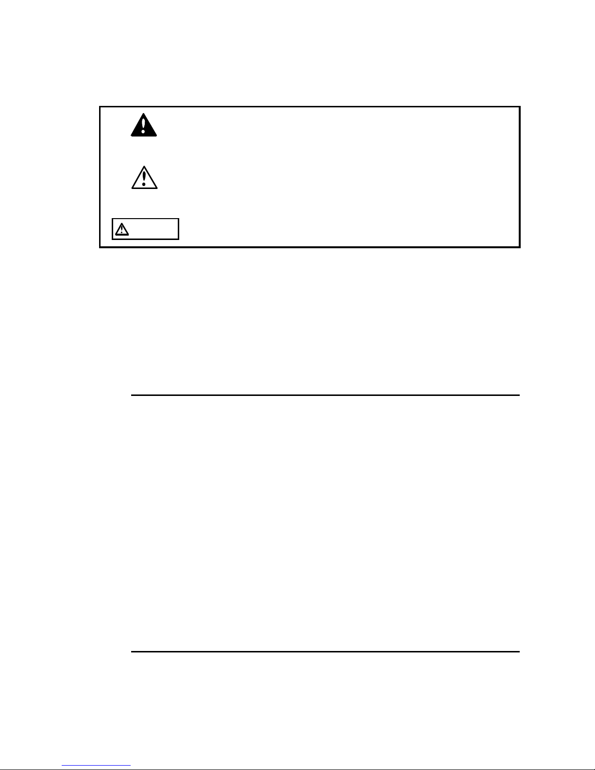
DANGE
R
Indicates that incorrect operation presents extreme
danger of accident resulting in death or serious injury
to the user.
WARNING
Indicates that incorrect operation presents significant
danger of accident resulting in death or serious injury
to the user.
CAUTION
Indicates that incorrect operation presents possibility
of injury to the user or damage to the equipment.
f.s.
(maximum display or scale value, or length of scale)
Signifies the maximum display (scale) value or the length
of the scale (in cases where the scale consists of unequal
increments or where the maximum value cannot be
defined).
In general, this is the range value (the value written on
the range selector or equivalent) currently in use.
rdg.
(displayed or indicated value)
This signifies the value actually being measured, i.e., the
value that is currently indicated or displayed by the
measuring instrument.
dgt.
(resolution)
Signifies the smallest display unit on a digital measuring
instrument, i.e., the value displayed when the last digit on
the digital display is "1".
The following symbols are used in this Instruction Manual
to indicate the relative importance of cautions and
warnings.
Accuracy
The specifications in this manual include figures for
"measurement accuracy" when referring to digital
measuring instruments, and for "measurement tolerance"
when referring to analog instruments.
Page 8
iv
_____________________________________________________________________
Safety Notes
______________________________________________________________
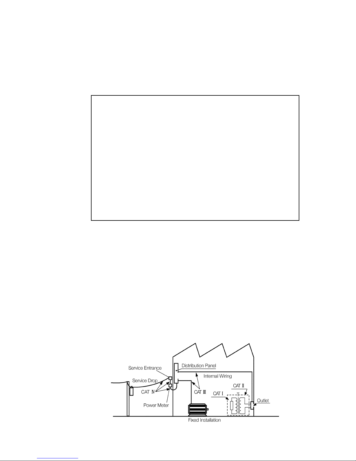
CAT I
Secondary electrical circuits connected to an AC
electrical outlet through a transformer or similar
device.
CAT II
Primary electrical circuits in equipment connected
to an AC electrical outlet by a power cord (portable
tools, household appliances, etc.)
CAT III
Primary electrical circuits of heavy equipment
(fixed installations) connected directly to the
distribution panel, and feeders from the distribution
panel to outlets.
CAT IV
The circuit from the service drop to the service
entrance, and to the power meter and primary
overcurrent protection device (distribution panel).
Measurement categories (Overvoltage categories)
To ensure safe operation of measurement product, IEC
61010 establishes safety standards for various electrical
environments, categorized as CAT I to CAT IV, and called
measurement categories. These are defined as follows.
Higher-numbered categories correspond to electrical
environments with greater momentary energy. So a
measurement device designed for CAT III environments can
endure greater momentary energy than a device designed for
CAT II. Using a measurement product in an environment
designated with a higher-numbered category than that for
which the product is rated could result in a severe accident,
and must be carefully avoided.
Never use a CAT I measuring product in CAT II, III, or IV
environments. The measurement categories comply with the
Overvoltage Categories of the IEC60664 Standards.
Page 9
v
_____________________________________________________________________
Notes on Use
______________________________________________________________
DANGE
R
To avoid short circuit and the risk of accidental injury
or death, working voltage must be under AC300 Vrms
(CAT III) for 9650 and under AC600 Vrms (CAT III) for
9651.
The maximum rated voltage to earth of clamp sensor
must be under AC300 Vrms for 9650 and under AC600
Vrms for 9651.
Do not measure voltage in excess of these limitations,
as doing so may damage the unit or cause an accident
that might result in injury or death.
Clamp sensor should only be connected to the
secondary side of a breaker, so the breaker can prevent
an accident if a short circuit occurs. Connections
should never be made to the primary side of a breaker,
because unrestricted current flow could cause a
serious accident if a short circuit occurs.
WARNING
To avoid electric shock, do not allow the product to get
wet, and do not use it when your hands are wet.
CAUTION
To avoid electric shock when measuring live lines, wear
appropriate protective gear, such as insulated rubber
gloves, boots and a safety helmet.
This product is designed for indoor use, and operates reliably from
0to50
.
Do not store or use the product where it could be exposed to
direct sunlight, high temperature or humidity, or condensation.
Under such conditions, the product may be damaged and
insulation may deteriorate so that it no longer meets
specifications.
Notes on Use
In order to ensure safe operation and to obtain maximum
performance from the unit, observe the cautions listed
below.
Page 10
vi
_____________________________________________________________________
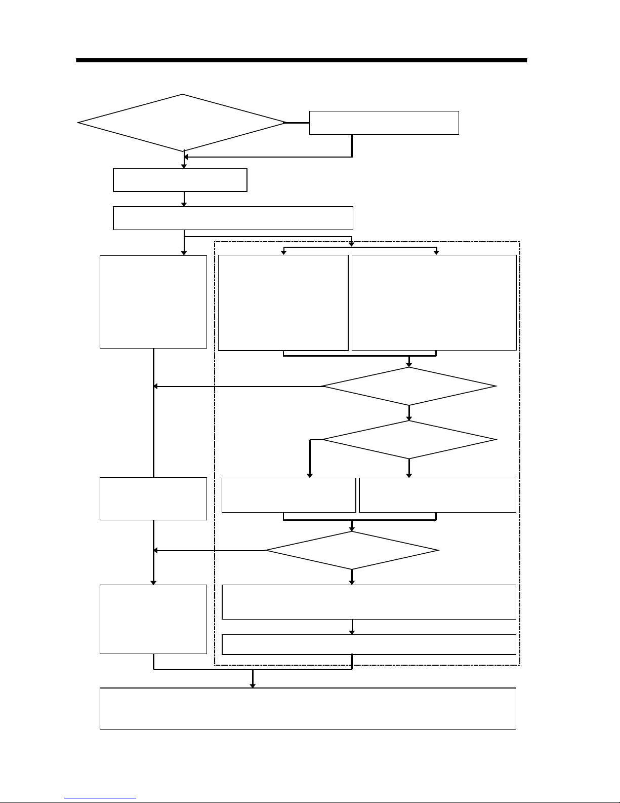
Measurement Flow Chart and Reference Guide
______________________________________________________________
Is there sufficient
battery charge remaining
to operate 3
636-20?
Replace batteries
Setting current time
Setting 3636-20
stand-alone
・Interval
・Number of
channels
・Recording mode
・Range
Setting 3636-20 with
COMMUNICATION
BASE
・Interval
・Current time
・Start control
・Recording method
Setting 3636-20 with
COMMUNICATION BASE and PC
・Interval ・Current time
・Start control ・Range
・Recording method
・Number of channels
・Recording mode
・Alarm ・Comment
See 2.1.
See 3.2.
Connecting clamp on sensor/connection cables
See 2.4.
Press REC/STOP
button to start
measurement.
Settingstart control
Start control options
No
Yes
Quick start
Prescheduled start
Starts measurement
immediately.
Starts measurement at
prescheduled time.
Setting
recordingmethod
Endless
One time
When recording data
reaches 32000
(
16000 in 2 channels
),
measurement stops.
When recording data exceeds 32000(
16000 in 2 channels
), it
overwrites previously recorded data.
Press REC/STOP button to stop measurement.
After measurement is complete, disconnect sensor cables.
Use COMMUNICATION BASE to send measurement data to personal computer.
(See COMMUNICATION BASE instruction manual.)
See 3.2.
Set current time when using 3636-20 for the
first time or replacingbatteries. See 2.3.
Measurement Flow Chart and Reference Guide
Page 11
1
_____________________________________________________________________
Product Outline
______________________________________________________________
3636-20 CLAMP LOGGER cannot be set with
3910-20 COMMUNICATION BASE.
Chapter 1
Product Outline
3636-20 CLAMP LOGGER with clamp on sensor records 1
or 2 channels of data at current value.
9650 CLAMP ON SENSOR enables effective value
measurement with intervals and recording up to 100 Arms
AC current and when using 9651 CLAMP ON SENSOR,
up to 500 Arms.
With two optional recording modes; recording instantaneous
value and recording average value, extended duration of
current recording is possible with battery operation.
Data is saved in nonvolatile memory when batteries are
weak or removed for replacement.
Page 12
2
_____________________________________________________________________
Product Outline
______________________________________________________________
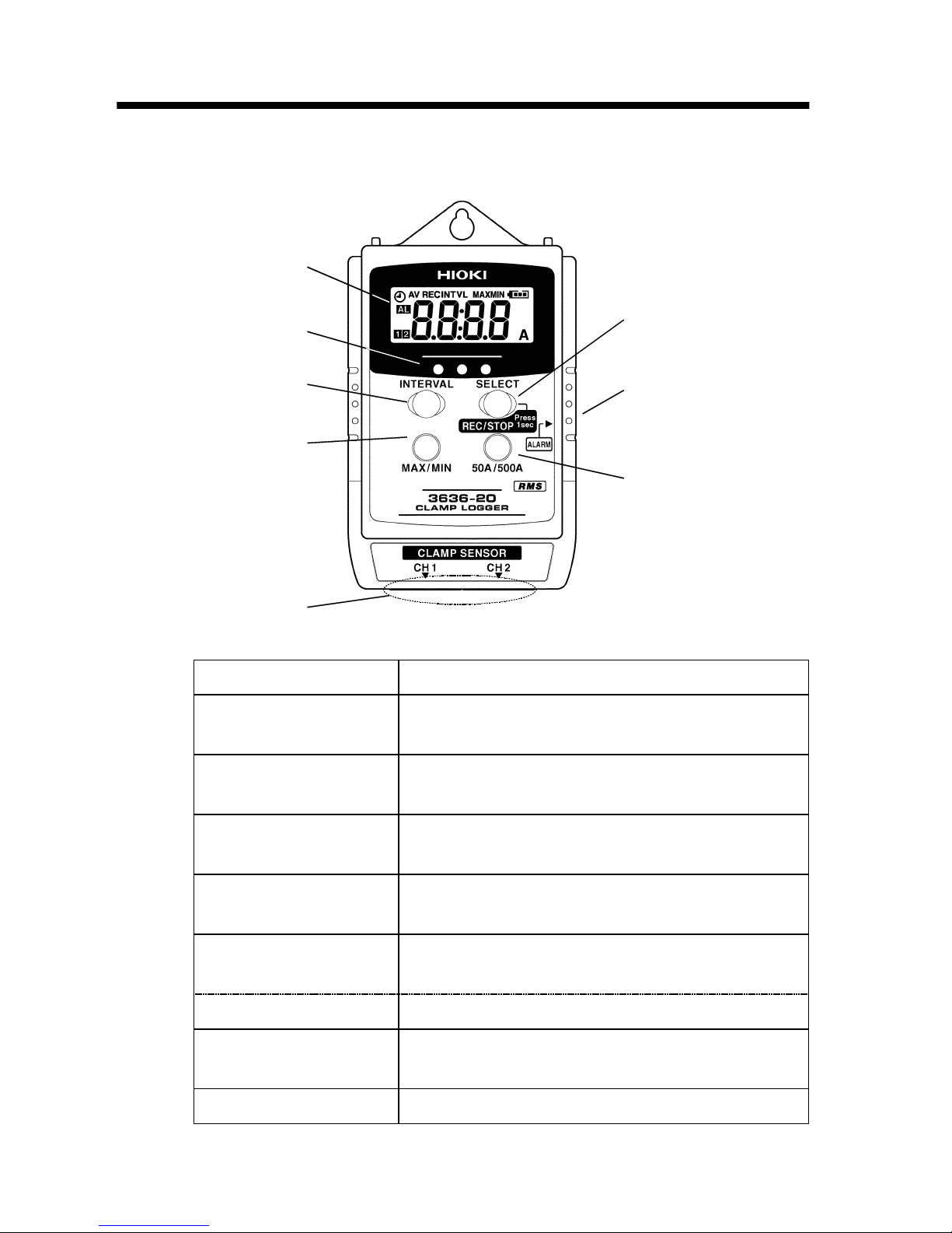
1
2
3
4
6
7
5
8
1. LCD Displays measurement value and settings.
2. Optical data transfer
ports
Enables optical data transfer to
COMMUNICATION BASE.
3. INTERVAL button Calls up interval setting display to set interval,
recording mode and measurement channels.
4. MAX./MIN. button Displays maximum value or minimum value of
recorded data.
5. Clamp connection
terminal
Connects 9650 or 9651 CLAMP ON SENSOR.
6. REC/STOP button Pressing more than 1 second initiates or stops
recording.
(SELECT) button Interval is selected in interval setting display.
7. Alarm output
terminal
Connects 9632 CONNECTION CABLE and
outputs alarm signal (open drain output).
8. 50A/500A button Changes measurement range from 50A/500A.
1.1 Name and Functions of Parts
Page 13

3
_____________________________________________________________________
Product Outline
______________________________________________________________
INTVL Maximum Recording Time
1s 4h26min40s
2s 8h53min20s
5s 22 h 13 min 20 s
10 s 1 day 20 h 26 min 40 s
15 s 2 day 18 h 40 min
20 s 3 day 16 h 53 min 20 s
30 s 5 day 13 h 20 min
1min 11 day 2 h 40 min
2min 22 day 5 h 20 min
5min 55 day 13 h 20 min
10 min 111 day 2 h 40 min
15 min 166 day 16 h
20 min 222 day 5 h 20 min
30 min 333 day 8 h
60 min 666 day 6 h
1.2 Interval and Maximum Recording Time
The table below shows the record interval and the
maximum recording time (when instantaneous values are
recorded with the power save function enabled).
The maximum recording time varies depending on the
remaining power level of the battery.
When average values are recorded with the power save
function enabled, the recording time will be approximately
one month.
When 3636-20 CLAMP LOGGER is used in 2 channels,
maximum recordable data is 16000 per unit.
Page 14

4
_____________________________________________________________________
Product Outline
______________________________________________________________
INTVL Maximum Recording Time
1s 8h53min20s
2s 17 h 46 min 40 s
5s 1 day 20 h 26 min 40 s
10 s 3 day 16 h 26 min 40 s
15 s 5 day 13 h 20 min
20 s 7day9h46min40s
30 s 11 day 2 h 40 min
1min 22 day 5 h 20 min
2min 44 day 10 h 40 min
5min 111 day 2 h 20 min
10 min 222 day 5 h 20 min
15 min 333 day 8 h
20 min 444 day 10 h 40 min
30 min 666 day 6 h
60 min 1333 day 8 h
When 3636-20 CLAMP LOGGER is used in 1 channel,
maximum recordable data is 32000 per unit.
Page 15

5
_____________________________________________________________________
Product Outline
______________________________________________________________
Maximum 400 points partitioned
at complete cycle
250µs
Interval
Records instantaneous value
Interval
One second interval
Recordingstarts Records averagevalue
1.3 Measurement Value Recording Modes
Effective value calculation
To calculate effective value, measurement signal is sampled
every 250 µs and operation is carried out from data with
maximum 400 points to seek effective value.
Recording instantaneous value
To record instantaneous value, calculate effective value only
oncepersetintervalandrecordinmemory.
Recording average value
To record average value, calculate effective value only once
per second and record average value of all data within
interval in memory.
After recording starts, average value within interval is
recorded, so the initial data is not recorded immediately
after recording starts but is recorded from the following
interval.
Page 16

6
_____________________________________________________________________
Product Outline
______________________________________________________________
Page 17

7
_____________________________________________________________________
Set Up
______________________________________________________________
WARNING
To avoid electric shoc
k when replacing the batteries,
first disconnect the connection cables from the object
to be measured.
During battery replacement, use caution not to put any
foreign materials such as a metal object into the unit to
avoid damage to the unit.
After replacing the batteries, replace the cover and
screws before using the product.
Do not mix old and new batteries, or different types of
batteries. Also, be careful to observe battery polarity
during installation. Otherwise, poor performance or
damage from battery leakage could result.
Handle and dispose of batteries in accordance with
local regulations.
Chapter 2
Set Up
2.1 Installing or Replacing the Batteries
Page 18

8
_____________________________________________________________________
Set Up
______________________________________________________________
Installing new batteries ensures about 1 year of
instantaneous value recording (when interval is set at more
than 1 minute) and about 1 month of average value
recording. (reference value with power save setting set to
valid and at 20
)
Remaining battery power indicator (
)indicates
remaining battery life reducing incrementally from right.
Empty battery power indicator (
) indicates time to
replace batteries.
(1) Remove back cover screw to remove cover. Verify
polarity and install four new LR03 alkaline batteries.
(2) Fit cover properly and tighten screw.
Page 19

9
_____________________________________________________________________
Set Up
______________________________________________________________
Sleeping......
See COMMUNICATION BASE instruction
manual to connect logger and to install
application software. To use application
software, see operation guide.
2.2 Power Save Function
Display window is automatically turned off in
approximately 15 seconds after last key entry. (Sleep)
However, while recording, REC/AV/ / / AL mark
shows each conditions.
Press any button to turn display on to display measurement
value or to set settings.
Note when interval setting display is on, sleep does not
engage with no button press.
Initially, power save function is on. To turn off power save
function, follow the instructions below.
When power save function is off, maximum continuous
duration is approximately 15 days.
(1) Connect logger, COMMUNICATION BASE and
personal computer.
(2) Start up application software packaged with
COMMUNICATION BASE.
(3) Go to Communications on the menu bar and select
Power Save Options. Choose Off to turn off power save
function.
Page 20

10
_____________________________________________________________________
Set Up
______________________________________________________________
2.3 Setting Current Time
When replacing 3636-20 CLAMP LOGGER batteries or
using 3636-20 stand-alone (with manual operation) for the
first time, connect with COMMUNICATION BASE and set
current time.
See how to set current time in COMMUNICATION BASE
instruction manual.
Page 21

11
_____________________________________________________________________
Set Up
______________________________________________________________
WARNING
Maximum input current for 9650 is 100 Arms, 9651 is
500 Arms. Do not exceed the continuous maximum
input current.
To avoid short circuit and the risk of accidental injury or
death, working voltage must be under AC300 Vrms (CAT
III) for 9650 and under AC600 Vrms (CAT III) for 9651.
When the clamp sensor is opened, do not allow the
metal part of the clamp to touch any exposed metal, or
to short between two lines, and do not use over bare
conductors.
When connecting with 9650 CLAMP ON SENSOR and
3636-20 measurement range is set at 50 A, do not
exceed 50 Arms.
To avoid damaging the unit, do not use any other
sensors except 9650 or 9651 CLAMP ON SENSOR as
sensor connector.
9650 or 9651
CLAMP ON SENSOR
9650 9651
Carefully read 9650 and 9651 CLAMP ON
SENSOR instruction manuals before use.
Improper measurement method may result in
accidental injury, death or damage in the unit.
2.4 Connecting Sensor/Cable
Connecting clamp on sensor
3636-20 CLAMP LOGGER enables 2 channels of data
measurement when connected with 9650 or 9651 CLAMP
ON SENSOR.
When measuring, affix clamp to one conductor only.
Page 22

12
_____________________________________________________________________
Set Up
______________________________________________________________
9632 CONNECTION CABLE
GND
non connection
White: Signal
Black: GND
Signal
Cord length: 1000 mm
Connecting 9632 CONNECTION CABLE
Connecting 9632 CONNECTION CABLE to alarm output
terminal.When connecting connection cable, securely insert
connection cable to unit as designated by triangle mark ▲
on connection terminal.
Improper connection results in failure to output accurate
signal.
9632 CONNECTION CABLE
Page 23

13
_____________________________________________________________________
Settings
______________________________________________________________
3636-20
3636-20+
COMMUNICATION
BASE
3636-20+
COMMUNICATION
BASE+PC
1. Start recording Vaild Vaild Vaild
2. Stop recording Vaild --- ---
3. Interval setting Vaild Vaild Vaild
4. Current time setting --- Vaild Vaild
5. Start control --- Vaild Vaild
6. Recording method setting --- Vaild Vaild
7. Range setting Vaild --- Vaild
8. Setting number of channels Vaild --- Vaild
9. Recording mode setting Vaild --- Vaild
10. Alarm setting --- --- Vaild
11. Comments --- --- Vaild
12. Minimum/
Maximum value display
Vaild --- ---
・
When PC, COMMUNICATION BASE and
3636-20 are connected, separate range can
be set in each channel. Once settings are set,
range setting with manual operation sets
common range.
・
Alarm and comment setting are available
when personal computer is connected to both
logger and COMMUNICATION BASE.
Chapter 3
Settings
3.1 Setting Items
Logger stand-alone manual settings and settings in
combination with COMMUNICATION BASE with
measurement conditions stored in memory loaded from
personal computer.
Page 24

14
_____________________________________________________________________
Settings
______________________________________________________________
1. Start recording
Start manual recording by pressing logger REC/STOP
button for 1 second or initiate by prescheduled start set
using COMMUNICATION BASE.
When time scheduled start is engaged, clock icon appears
in display. When batteries are weak, recording does not
start. During recording, weak battery interrupts recording.
2. Stop recording
Stop recording by pressing logger REC/STOP button for 1
second. Or recording stops automatically when data is full
when set to recording method: one time.
3. Interval setting
Set interval with logger alone or using COMMUNICATION
BASE. (1/2/5/10/15/20/30 s, 1/2/5/10/15/20/30/60 min)
4. Current time setting
To set current time, see COMMUNICATION BASE
instruction manual.
5. Start control
Set specific recording date and time using
COMMUNICATION BASE to engage time scheduled start.
When time scheduled start is engaged, clock icon appears
in display.
6. Recording method setting
Set recording method using COMMUNICATION BASE.
Choose either one time or endless recording method.
Default setting is one time.
One time: Ends recording when data reaches 32000
(2 ch: 16000).
Endless : Overwrites previously recorded data when data
exceeds 32000 (2 ch: 16000).
Page 25

15
_____________________________________________________________________
Settings
______________________________________________________________
When using 9650, set at 50 A or 500 A.
When 3636-20 measurement range is set at 50
A, do not exceed 50 Arms.
When using 9651, set at 500 A.
When PC, COMMUNICATION BASE and 363620 are connected, separate range can be set in
each channel. Once settings are set, range
setting with manual operation sets common
range.
7. Range setting
With 3636-20 stand-alone, or connected with
COMMUNICATION BASE and PC, range setting is
available.
Two measurement range options are 50.00 A range and
500.0 A.
Select and set in accordance with clamp on sensor. When
manually operated, common settings apply to channel 1 and
channel 2.
8. Setting number of channels
With 3636-20 stand-alone, or connected with
COMMUNICATION BASE and PC, setting is available.
Select input for channel 1 or channel 2.
At factory shipment settings, both channel 1 and channel 2
are valid.
Page 26

16
_____________________________________________________________________
Settings
______________________________________________________________
Average value recording mode records average
value within interval, so the initial data is not
recorded immediately after recording starts but
is recorded from the following interval.
For example, when measurement started at
12:00 at 1 minute intervals, the first data is data
recorded when 1 minute has passed at 12:01.
Alarm signal output terminal is an open drain
output. During signal output, signal side and
GND side are internally grounded and any other
time, it remains open. When external power
supply is supplied, alarm signal can control
relay or sequencer. Maximum rate: 30 V, 200
mA (allowable loss 200 mW)
9. Recording mode setting
With 3636-20 stand-alone, or connected together with
COMMUNICATION BASE and PC, setting is available.
Two recording mode options are instantaneous value
recording and average value recording (AV displayed).
At factory shipment setting, average value recording is
selected.
10. Alarm setting
Alarm setting is available when 3636-20,
COMMUNICATION BASE and personal computer are
connected.
Designate upper limit and lower limit value of measurement
value with personal computer to output alarm signal when
measurement value goes outside of set range. Two channels
pass individual judgment.
During signal output, AL appears on the display.
Page 27

17
_____________________________________________________________________
Settings
______________________________________________________________
・
Maximum value and minimum value are from
data recorded in memory and may vary from
each displayed value per second.
・
When recording method is set as endless,
maximum value and minimum value from the
beginning of recording are displayed. When
old data is overwritten after extended
recording, data currently recorded may differ
from displayed maximum value and minimum
value.
11. Comments
Set comments entered by personal computer to logger using
COMMUNICATION BASE. When sorting collected
recording data, comments are helpful.
Comment setting is available when personal computer is
connected to both logger and COMMUNICATION BASE.
12. Maximum/Minimum value display
3636-20 stand-alone enables maximum/minimum value
display settings. Maximum value or minimum value of
recorded data is alternately displayed.
Page 28

18
_____________________________________________________________________
Settings
______________________________________________________________
3.2 Manual Setting
3636-20 CLAMP LOGGER stand-alone manual operation
settings are shown below.
(1) Interval setting
Press INTERVAL button to switch measurement value
display to interval setting display. (INTVL appears.)
Press SELECT button to designate interval.
Press INTERVAL button to complete setting.
(2) Setting number of channels
Press INTERVAL button to display interval setting
display.
Each 50A/500A button press selects channel to be used.
When channel 1 is selected, only display "
"isturned
on and when channel 2 is selected, display "
"is
turned on. When both channel 1 and channel 2 are
selected, display "
" is turned on.
(3) Setting recording mode
Press INTERVAL button to display interval setting
display.
Each MAX/MIN button press alternates and selects
instantaneous value recording and average recording
(AV displayed).
To set instantaneous value recording and average
recording, see 1.3 Measurement Value Recording
Modes.
Page 29

19
_____________________________________________________________________
Settings
______________________________________________________________
50 A range 500 A range
(4) Setting range
Press 50A/500A button on monitor screen to select 50A
or 500A.
When measurement range is reselected, decimal point
moves its position.
To set 3636-20 measurement range, select 50 A or
500A with 9650 and 500A with 9651.
When manual operation is conducted, common range
settings apply to both channel 1 and channel 2.
(5) Starting and ending recording
Press REC/STOP button for 1 second to clear last
recorded data and start recording. (REC appears.)
Press REC/STOP button for 1 second to stop recording.
When memory is full, recording automatically stops
when recording method: one time is selected.
When batteries are weak, recording does not start.
During recording, weak batteries interrupt recording.
(6) Maximum/Minimum value display
Press [MAX/MIN] button to display maximum or
minimum value from recorded data.
Each button press alternates display.
Page 30

20
_____________________________________________________________________
Settings
______________________________________________________________
・
Previously recorded logger data is erased
when recording is resumed. Be sure to load
data to be saved to COMMUNICATION BASE
or to personal computer before recording.
・
At any other time even when interval setting
display is not shown, except during recording
and waiting for recording, communication with
COMMUNICATION BASE is available.
However communication is disabled when
logger is set to sleep.
3.3 Setting by COMMUNICATION BASE
(1) Press logger INTERVAL button lightly to display LCD.
(2) When logger LCD shows REC mark or clock icon,
press REC/STOP button for more than 1 second to stop
recording.
During recording or waiting time before recording start
time, data transfer cannot be established with
COMMUNICATION BASE.
(3) Press logger INTERVAL button to display interval
setting display. (INTVL appears.)
(4) Connect COMMUNICATION BASE with logger.
(5) Press COMMUNICATION BASE SEND button for
more than 1 second to send data settings to logger.
Page 31

21
_____________________________________________________________________
Settings
______________________________________________________________
・
Comment, recording mode, measurement channel,
range and alarm setting are only available in 3636
setting items. Personal computer,
COMMUNICATION BASE and 3636-20 must be
connected during setting.
・
Common settings are available to be set in '3911,
3912' settings.
3636-20 settings in application software
COMMUNICATION UTILITY packaged with
COMMUNICATION BASE are as follows.
Go to 'Communication' on the menu bar in
COMMUNICATION UTILITY and select 'Set measurement
condition'. When measurement condition setting window is
open, select '3636' setting items to set settings.
Page 32

22
_____________________________________________________________________
Settings
______________________________________________________________
Page 33

23
_____________________________________________________________________
Specifications
______________________________________________________________
Sensor types
9650, 9651 CLAMP ON SENSOR
Input AC current
Maximum input
current
AC0.6 Arms, 1 A peak value
Number of input 2 channels
(1 or 2 channels settable from personal computer)
Measurement
range
0to500A
Range structure 50.00 A, 500.0 A
Measurement
method
True effective value calculation
Measurement
accuracy
Unit : 1% rdg. 5 dgt. (50/60 Hz)
Unit + Sensor :
2.5% rdg. 8 dgt. (50/60 Hz)
When 9650 is in use, range at 50 A, 500 A.
When 9651 is in use, range at 500 A.
Operating temperature and
humidity for guaranteed
accuracy
Guaranteed
accuracy period
23 5 (73 9 ), 80%RH or less
1 year
Interval for
effective value
calculation
1 time per second
LCD display Measurement value, Interval, Battery status
(remaining battery power indicator: 4 phases)
Unit (A), recording (REC), prescheduled(
),
average value recording (AV), maximum value
(MAX), minimum value (MIN), alarm (AL)
Recording mode Recording instantaneous value
Recording average value (records average value
within interval)
Interval 1/2/5/10/15/20/30 s, 1/2/5/10/15/20/30/60 min
Recording
capacity
32,000 data X 1 channel
16,000 data X 2 channels
Recording start Manual start, Prescheduled start
Recording stop Manual stop, Memory full
Recording
method
One time, Endless
Chapter 4
Specifications
Page 34

24
_____________________________________________________________________
Specifications
______________________________________________________________
Displaying
Max/Min value
Displays maximum value and minimum value.
Alarm output Turns ON (open drain output) when value goes
outside previously set upper limit or lower limit.
Data backup Available
(Data not erased by weak batteries or battery
replacement)
Interface Infrared optical data transfer
Power supply LR03 alkaline battery X 4 (1.5 VDC X 4)
Maximum rated
power
0.1 VA
Battery life About one year
(temperature at 20
, power save function: valid,
when instantaneous value recording at 1 minute
intervals is selected)
About one month
(temperature at 20
, power save function: valid,
when average value recording is selected)
Dimensions Approx. 57W X 86H X 30D mm
(2.24"W X 3.39"H X 1.18"D) (excluding projections)
Mass Approx. 130 g (4.6 oz) (including batteries)
Location for use Indoors, altitude up to 2000 m (6562 feet)
Operate
temperature and
humidity range
0to50 (32 to 122 ), 80% RH or less
(no condensation)
Storage
temperature and
humidity range
-10 to 60 (14 to 140 ), 80% RH or less
(no condensation)
Accessories LR03 alkaline battery X 4
9632 CONNECTION CABLE
Instruction Manual
Options 3911-20 COMMUNICATION BASE
3912-20 COMMUNICATION BASE
9650 CLAMP ON SENSOR
9651 CLAMP ON SENSOR
Standards
Applying
EMC
EN61326:1997+A1:1998+A2:2001+A3:2003
Safety
EN 61010-1:2001 Pollution Degree 2
Page 35

25
_____________________________________________________________________
Maintenance and Service
______________________________________________________________
Chapter 5
Maintenance and Service
Cleaning
To clean the product, wipe it gently with a soft cloth
moistened with water or mild detergent. Never use solvents
such as benzene, alcohol, acetone, ether, ketones, thinners
or gasoline, as they can deform and discolor the case.
Wipe the LCD gently with a soft, dry cloth.
Service
If the product seems to be malfunctioning, confirm that the
batteries are not discharged, and that the probes are not
open circuited before contacting your dealer or Hioki
representative.
Page 36

26
_____________________________________________________________________
Maintenance and Service
______________________________________________________________
--MEMO--
Page 37

Page 38

Page 39

HIOKI 3636-20 CLAMP LOGGER
Instruction Manual
Publication date: September 2006 Revised edition 4
Edited and published by HIOKI E.E. CORPORATION
Technical Support Section
All inquiries to International Sales and Marketing Department
81 Koizumi, Ueda, Nagano, 386-1192, Japan
TEL: +81-268-28-0562 / FAX: +81-268-28-0568
E-mail: os-com@hioki.co.jp
URL http://www.hioki.co.jp/
Printed in Japan 3636A981-04
All reasonable care has been taken in the production of this manual,
but if you find any points which are unclear or in error, please
contact your supplier or the International Sales and Marketing
Department at HIOKI headquarters.
In the interests of product development, the contents of this manual
are subject to revision without prior notice.
Unauthorized reproduction or copying of this manual is prohibited.
Page 40

HEAD OFFICE
81 Koizumi, Ueda, Nagano 386-1192, Japan
TEL +81-268-28-0562 / FAX +81-268-28-0568
E-mail: os-com@hioki.co.jp / URL http://www.hioki.co.jp/
HIOKI USA CORPORATION
6 Corporate Drive, Cranbury, NJ 08512, USA
TEL +1-609-409-9109 / FAX +1-609-409-9108
3636A981-04 06-09H
Printed on recycled paper
 Loading...