

Page 1

BATTERY HiTESTER
INSTRUCTION MANUAL
3561
3561-01
Page 2

Page 3
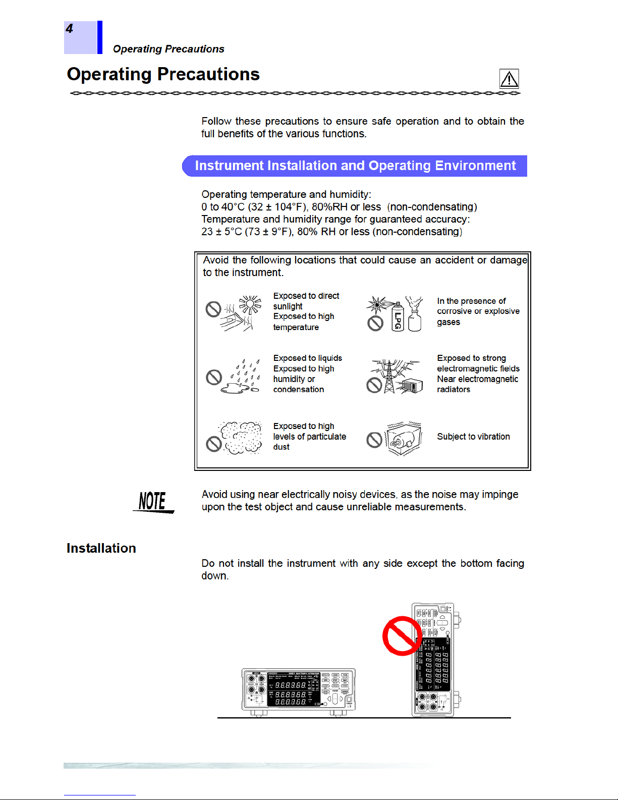
Page 4

Contents
ii
Chapter 4
Applied Measurement _______________________33
4.1 Comparator Fun ctio n...................... .. ................. ... .. .. .. 34
4.1.1 Comparator Setting Example 1
(Upper and Lower Threshold Judgment) ......................35
4.1.2 Comparator Setting Example 2
(Reference Value and Tolerance Judgment) ................39
4.1.3 Comparator Judgment Beeper Setting ............. .... ..... ...43
4.1.4 Comparator Execution Mode Setting ............................44
4.1.5 Comparator Threshold Method Selection .....................45
4.1.6 Upper and Lower Thresholds Setting
(by Reference Value and Tolerance) ............................46
4.1.7 Enabling and Disabling the Comparator Function ........48
4.1.8 Comparator Judgment Results .....................................49
4.1.9 Switching Between Measurement Value and
Comparator Setting Displays ........................................ 50
4.2 Trigger Function ......................................................... 51
4.2.1 Trigger Source Settings ................................................51
4.2.2 Trigger Delay Settings ..................................................52
4.3 Averaging Function..................................................... 53
4.4 Statistical Calculation Functions................................. 54
4.5 Memory Function........................................................ 58
4.6 Key-Lock Function...................................................... 60
4.7 Panel Save Function..................................................61
4.8 Panel Load Function........ .. ...................... ...................62
4.9 Self-Calibration........................................................... 63
4.10 Measurement Value Output Function......................... 64
4.11 Key Beeper Setting..................................................... 65
4.12 Reset Function ....... .. ... .. ............................................. 66
Chapter 5
External Control ____________________________69
5.1 Overview..................................................................... 69
5.2 Signal Descriptions................................................ .. ... 70
5.2.1 Pinout ............................................................................70
5.2.2 Input Signals ...... ..... .... ..... .............................................71
5.2.3 Output Signals ..............................................................72
5.2.4 ERR Output ..................................................................73
5.2.5 Instrument Settings .......................................................74
5.3 Timing Chart............. .................... .............................. 75
5.4 Internal Circuitry ......................................................... 77
Page 5

Contents
iii
Chapter 6
Printer (Optional) ___________________________ 79
6.1 Connecting the Pr inter .................... ............................80
6.1.1 Connecting the 9670 PRINTER to the Instrument ........81
6.1.2 Loading Recording Paper .............................................82
6.1.3 Charging the Battery Pack ............................................83
6.1.4 Installing the Battery Pack in the Printer .......................83
6.2 Selecting the Inte rfa c e .......... .. .. ..................................84
6.3 Setting of the 9670 PRINTER............................ .........84
6.4 Printing........................................................................85
Chapter 7
RS-232C/GP-IB Interfaces ____________________ 87
7.1 Overview and Features....................................... ........87
7.2 Specifications..............................................................88
7.2.1 RS-232C Specifications ............................................. ...88
7.2.2 GP-IB Specifications (Model 3561-01 only) ..................88
7.3 Selecting the Connections and Protocol....................89
7.3.1 Attaching the Connector ................................................89
7.3.2 Selecting the Interface ............... .... ..... ..... .....................91
7.4 Communication Methods ............................................92
7.4.1 Message Format ...........................................................92
7.4.2 Output Queue and Input Buffer .....................................97
7.4.3 Status Byte Register .....................................................98
7.4.4 Event Registers ...........................................................100
7.4.5 Initialization Items ........................................................103
7.4.6 Local Function .............................................................103
7.5 Message List.................................... .........................104
7.5.1 Standard Commands ..................................................104
7.5.2 Device-Specific Commands ........................................105
7.6 Message Reference....... .................. .........................110
7.6.1 Standard Commands ..................................................111
7.6.2 Device-Specific Commands ........................................115
7.6.3 Measurement Value Formats ......................................141
7.6.4 Command Compa t ib il it y wit h the Model 3560
AC mΩ HiTESTER .....................................................142
7.7 Basic Data Importing Methods..................................146
7.8 Sample Progra m s ......... ... .. ................. .. ... .................14 7
Page 6

Contents
iv
Chapter 8
Specifications_____________________________157
8.1 Basic Specifications.................................................. 157
8.2 Accuracy................................................................... 161
8.3 General Specifications..............................................162
Chapter 9
Maintenance and Service ___________________163
9.1 Troubleshooting........................................................163
9.2 Cleaning ................................................................... 164
9.3 Error Display............................................................. 164
Appendix_________________________________165
Appendix 1 Precautions for Making Custom Te st Leads .. 165
Appendix 2 AC Four-terminal Method............................... 167
Appendix 3 Synchronous Detect ion System.....................168
Appendix 4
Configuration and Extension of the Test Leads
.. 169
Appendix 5 Effect of Eddy Currents.................................. 170
Appendix 6 Calibration Procedure............... ..................... .171
Appendix 7 Test Lead Opti ons.......................................... 172
Appendix 8 Rack Mounting...............................................173
Appendix 9 Dimensional Diagram................................ ..... 175
Index ______________________________________ i
Page 7
Page 8
Page 9
Page 10
Page 11
Page 12
Page 13
Page 14
Page 15
Page 16
Page 17
Page 18
Page 19
Page 20
Page 21
Page 22
Page 23
Page 24
Page 25
Page 26
Page 27
Page 28
Page 29
Page 30
Page 31

Page 32

Page 33

Page 34

Page 35

Page 36

Page 37

Page 38

3.7 Displaying Measurement Results
32
3.7.1 Measurement Fault Detection
If a measurement does not execute properly, a measurement fault
“- - - - -” is indicated on the display.
In addition, a measurement fault signal (ERR) is output at the EXT I/O
connector.
See Section 5.2.4 ERR Output (Page 73).
A measurement fault is displayed in the following cases.
• When a test lead is not connected to the test object
• When the resistance of the measured object is over-range
Example: Attempting to measure 30 Ω with the 300 mΩ range
selected.
• If any of the following is open, or has a bad connection: SOURCEH, SOURCE-L, SENSE-H, SENSE-L
• When the resistance between SOURCE-H and SOURCE-L is 50 Ω
or more in the 300 mΩ range (or 500 Ω or more in the 3 Ω range)
• When the resistance between SENSE-H and SENSE-L is greater
than about 20 Ω. (However, if the capacitance of the test leads is 1
nF or higher, the measurement fault may not be detected.)
• When a bad contact results from damage, excessive wear or
impurities on the test leads.
• If the circuit protection fuse is blown
See Section 9.1 Troubleshooting (Page 163).
3.7.2 Overflow Display
Overflow is indicated by “OF” or “-OF” on the display, caused by one of
the following:
Display Condition
OF
• The measured value exceeds the limit of the current
measurement range
• When the result of relative value calculation is larger
than +99.999%.
-OF
• The measured value is below the limit of the current
measurement range
• When the result of relati ve value calculation is smaller
than -99.999%.
Page 39

Page 40

Page 41

Page 42

Page 43

Page 44

Page 45

Page 46

Page 47

Page 48

Page 49

Page 50

Page 51

Page 52

Page 53

Page 54

Page 55

Page 56

Page 57

Page 58

Page 59

Page 60

Page 61

Page 62

Page 63

Page 64

Page 65

Page 66

Page 67

Page 68

Page 69

Page 70

Page 71

Page 72

Page 73

Page 74

4.12 Reset Function
68
Page 75

Page 76

Page 77

Page 78

5.2 Signal Descriptions
72
0ADJ Zero adjustment executes once when the 0ADJ signal transitions from
High to Low.
PRINT The current measurement value prints when the PRINT signal
transitions from High to Low.
MANU When the MANU comparator mode is selected, comparator judgment
is enabled while the
MANU signal is Low.
See Section 4.1.4 Comparator Execution Mode Setting (Page 44).
IN0 to IN4 The TRIG, CAL, 0ADJ, PRINT and MANU signals can also serve as
general-purpose input terminals, read with the
:IO:IN? command.
See Section EXT I/O Input (Page 134).
5.2.3 Output Signals
ERR Indicates a measurement fault.
The Synchronous ERR output setting causes ERR output to be
synchronous with EOC output, while with the Asynchronous ERR
output setting causes ERR output to follow actual (asynchronous)
contact of the probes with the test obje ct.
See Section 5.2.4 ERR Output (Page 73).
INDEX The INDEX signal is output during the Trigger Wait, Delay, Self-
Calibration and Calculation stat es.
This signal is not output while measuring the resi stance of test object s.
This signal transitions from Off to On to indicate that the test object
can be removed.
EOC This signal indicates the end of a measurement (End-Of-Conversion).
This signal indicates when comparator judgment results and ERR
output (when SYNC is enabled) are available.
R-Hi, R-IN, R-Lo
V-Hi, V-IN, V-Lo
These are the results of comparator deci sion.
AND This signal indicates when both resistance and voltage judgment
results are IN (ΩV mode).
In the Ω and V modes, this signal is the same as R-IN and V-IN
outputs, respectiv e ly.
OUT0 to OUT9 The output signals are controlled by the :IO:OUT command.
See Section EXT I/O Output (Page 134).
INT.GND This is the instrument's internal ground.
• I/O signals should not be used while measurement settings have
been changed.
• The EOC and INDEX signals are initialized (ON) at power on.
• If it is not necessary to change the measurement conditions, set
LOAD0 through LOAD6 to either Hi or Lo.
Page 79

Page 80

Page 81

Page 82

5.3 Timing Chart
76
Description
Time
t1
ERR Output response
time
*1
1.5 ms
t2
Measurement trigger
pulse width
0.5 ms min.
t3
Delay Time per setting
See Section 4.2.2 Trigger Delay Settings (Page 52).
t4
Measurement time
*2
ΩV mode
EX.FAST 6.8 ms
FAST 22.8 ms
MEDIUM 82.8 ms
68.8 ms
SLOW 257.8 ms
251.2 ms
Ω mode or V mode
EX.FAST 3.4 ms
FAST 11.4 ms
MEDIUM 41.4 ms (50 Hz line
frequency setting)
34.4 ms (60 Hz line
frequency setting)
SLOW 156.4 ms (50 Hz line
frequency setting)
149.8 ms (60 Hz line
frequency setting)
t5
Calculation time
*3
0.3 ms
t6
EOC Output pulse width When the external trigger is selected
HOLD setting : Holds until the next trigger is detected
PULSE setting : Remains only for the specified pulse width
See Section 5.2.5 Instrument Settings (Page 74).
When the internal trigger is selected
HOLD setting : EX.FAST 1 ms, FAST 5 ms, MEDIUM 20 ms, SLOW 50 ms
PULSE setting : Remains only for the specified pulse width
*1: For details, see “5.2.4 ERR Output (Page 73).”
*2
: About t4 measurement time
When averaging is enabled, the running average is obtained with internal triggering, so
measurement time t4 does not change. The measurement time for external triggering is as
follows:
With SLOW sampling
ΩV (t4 - 57.8) X n + 57.8 ms (50 Hz)
(t4 - 51.2) X n + 51.2 ms (60 Hz)
Ω or V (t4 - 56.4) X n + 56.4 ms (50 Hz)
(t4 - 49.8) X n + 49.8 ms (60 Hz)
With other than SLOW sampling
ΩV (t4 - 2.8) X n + 2.8 ms
Ω or V (t4 - 1.4) X n + 1.4 ms
(n represents the number of values averaged)
*3
: About t5 calculation time
In the following cases, add the indicated times to calculation time t5:
When the Statistical Calculation function is enabled 0.3 ms
When the ref erence value/tolerance method of
comparator decision is selected
0.15 ms
Page 83

Page 84

Page 85

Page 86

Page 87

Page 88

Page 89

Page 90

Page 91

Page 92

6.4 Printing
86
Example Printouts _____________________________________________
Statistical Calculations (Comparator ON)
*** RESISTANCE ***
Number 85
Valid 85
Average 13.06mOhm
Max 13.78mOhm( 74)
Min 12.10mOhm( 3)
Sn 0.38mOhm
Sn-1 0.38mOhm
Cp 1.32
CpK 0.09
Comp Hi 40
Comp IN 45
Comp Lo 0
*** VOLTAGE ***
Number 85
Valid 85
Average 10.0074 V
Max 10.0197 V ( 57)
Min 9.9938 V ( 31)
Sn 0.0068 V
Sn-1 0.0068 V
Cp 0.35
CpK 0.32
Comp Hi 10
Comp IN 59
Comp Lo 16
Measurement values
(V mode)
3132 4.2019 V
3133 15.2084 V
Measurement values
(ΩV mode)
1 298.60mOhm, 1.3924 V
2 0.2984 Ohm, 1.3924 V
3 - 3.35mOhm, 0.0000 V
4 - 0.0054 Ohm, 0.0000 V
5 299.10mOhm,- 1.3923 V
6 0.2984 Ohm,- 1.3923 V
7 3.57mOhm, 13.9071 V
8 - 16.89mOhm,-13.9088 V
Measurement values
(Ω mode)
15 209.98mOhm
16 0.2103 Ohm
With erroneous measurement values
10 O.F. , O.F.
11 - O.F. ,- O.F.
12 -------- ,------- 13 Invalid , Invalid
14 O.F. , 12.0097 V
15 - 19.82mOhm,- O.F.
With the Comparator ON
95 105.80mOhm Lo, 0.0000 V IN
96 213.15mOhm Hi
97 213.12mOhm IN
98 213.11mOhm Lo
99 10.0072 V Hi
100 10.0071 V IN
101 10.0070 V Lo
102 O.F. Hi, O.F. Hi
103 - 3.11mOhm Lo,- O.F. Lo
104 -------- --,-------- --
With the relative value comparison me thod
(reference value and tolerance)
84 0.023 % Hi, 0.001 % IN
85 0.014 % IN, 0.000 % IN
86 - 0.019 % Lo, 0.002 % IN
Interval prin t
00:00:00 13.74mOhm, 10.0138 V
00:00:01 13.87mOhm, 10.0138 V
00:00:02 13.67mOhm, 10.0139 V
00:00:03 13.47mOhm, 10.0138 V
00:00:04 13.58mOhm, 10.0139 V
00:00:05 13.58mOhm, 10.0139 V
00:00:06 13.68mOhm, 10.0139 V
Max/Min count
Measurement values indicated as "Invalid" cannot be displayed by
the instrument.
The number of statistical calculation results indicated as “Valid”
equals the count of valid data excluding measurement faults and
overflows.
Page 93

Page 94

Page 95

Page 96

Page 97

Page 98

Page 99

Page 100

7.4 Communication Methods
94
Message
Terminators
This instrument recognizes the following message terminators:
From the instrument's interface settings, the following can be selected
as the terminator for response messages.
See Section 7.3.2 Selecting the Interface (Page 91).
Separators
(1) Message Unit Separator
Multiple message can be written in one line by separating them with
semicolons ";".
• When messages are combined in this way and if one command
contains an error, all subsequent messages up to the next
terminator will be ignored.
• A query error occurs if a query command is combined with an
immediately following semicolon and subsequent command.
(2) Header Separator
In a message consisting of both a header and data, the header is
separated from the data by a space " ".
(3) Data Separator
In a message containing multiple data items, commas are required to
separate the data items from one another.
•LF
•CR+LF
•EOI
• LF with EOI
•CR
• CR+LF
• LF with EOI (initial setting)
• LF with CR and EOI
• CR + LF (initial setting)
:SYSTEM:LFREQUENCY 60;∗IDN?
:SYSTEM:ELOCK ON
 Loading...